Note: Descriptions are shown in the official language in which they were submitted.
CA 03161596 2022-05-13
WO 2021/097029 PCT/US2020/060139
HYBRID MECHANICALLY LINED PIPE METHODS AND APPARATUS
BACKGROUND
Field
paw Aspects of the present disclosure relate to methods of designing and
making
hybrid mechanically lined pipe, and apparatus thereof, such as lined pipe used
for
reel-lay operations.
Description of the Related Art
[0002] Joints of lined pipe used to make pipelines may have differing
properties.
The differing properties of the pipe joints can cause wrinkling of the liner
in the
pipeline when the pipe is bent, such as during reeling and unreeling of the
pipe. The
wrinkling can create operational issues, for example by inducing pressure
drop,
inhibiting pipeline pigging, and/or causing fracturing of liner.
[0003] Therefore, there is a need for simple and cost-effective methods of
making
lined pipe that facilitate reduced or eliminated liner wrinkling.
SUMMARY
[0004] Aspects of the present disclosure relate to methods of designing and
making
hybrid mechanically lined pipe, and apparatus thereof, such as lined pipe used
for
reel-lay operations.
[0005] In one implementation, a method of making a lined pipe for reel-lay
operations includes determining a minimum weld overlay length for a first pipe
joint,
and positioning the first pipe joint for liner operations. The first pipe
joint includes a
first end opposite of a second end, a central opening, and an inner surface.
The
method also includes disposing a first section of alloy in the central opening
of the
first pipe joint, and mechanically lining the inner surface of the first pipe
joint with the
first section of alloy. The method also includes weld overlaying a second
section of
alloy in the central opening and on a first side of the first section of
alloy. The weld
overlaying includes welding the second section of alloy to the inner surface
of the
SUBSTITUTE SHEET (RULE 26)
CA 03161596 2022-05-13
WO 2021/097029 PCT/US2020/060139
first pipe joint along a first length that is greater than or equal to the
minimum weld
overlay length.
[0006] In one implementation, a hybrid mechanically lined pipe includes a
spool,
and a pipeline reeled onto the spool. The pipeline includes one or more pipe
joints.
Each respective pipe joint of the one or more pipe joints includes a first
weld overlay
alloy welded to the respective pipe joint along a first length, a second weld
overlay
alloy welded to the respective pipe joint along a second length, and a liner
mechanically lined to the respective pipe joint. The liner is disposed between
the
first weld overlay alloy and the second weld overlay alloy. Each of the first
length
and the second length is greater than or equal to a minimum weld overlay
length to
reduce or prevent wrinkling of the liner.
[0007] In one implementation, a pipe includes a pipe joint, a liner
mechanically
lined to the pipe joint, and a weld overlay welded within the pipe joint. The
weld
overlay has a weld overlay length that is greater than or equal to a
predetermined
length to prevent wrinkling of the liner.
BRIEF DESCRIPTION OF THE DRAWINGS
[0oos] So that the manner in which the above-recited features of the
disclosure can
be understood in detail, a more particular description of the disclosure,
briefly
summarized above, may be had by reference to implementations, some of which
are
illustrated in the appended drawings. It is to be noted, however, that the
appended
drawings illustrate only typical embodiments of this disclosure and are
therefore not
to be considered limiting of its scope, for the disclosure may admit to other
equally
effective embodiments.
[0009] Figure 1A is a partial schematic view of a first pipe joint and a
second pipe
joint being reeled onto a spool, according to one implementation. This partial
schematic view shows only the two consecutive joints which are part of a much
longer assembly of joints called a stalk. Several stalks may be joined
together and
be reeled onto the spool.
2
SUBSTITUTE SHEET (RULE 26)
CA 03161596 2022-05-13
WO 2021/097029 PCT/US2020/060139
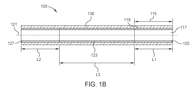
[0010] Figure 1B is a partial schematic view of the first pipe joint
illustrated in Figure
1A prior to being welded to the second pipe joint and reeled onto the spool ,
according to one implementation.
[0m] Figure 2A is a partial schematic view of a reeling system, according to
one
implementation.
[0012] Figure 2B is a partial schematic view of the offshore vessel and spool
disposed thereon, illustrated in Figure 2A, during an offshore pipe-laying
operation,
according to one implementation.
[0013] To facilitate understanding, identical reference numerals have been
used,
where possible, to designate identical elements that are common to the
figures. It is
contemplated that elements disclosed in one implementation may be beneficially
utilized on other implementations without specific recitation.
DETAILED DESCRIPTION
[0014] Aspects of the present disclosure relates to methods of making lined
pipe to
be used for reel-lay applications. The aspects disclosed herein facilitate
reduced or
eliminated liner wrinkling of liner inside the pipe during any bending cycle
associated
with reeling operations, such as reeling or unreeling of the pipe.
[0015] Figure 1A is a partial schematic view of a first pipe joint 103 and a
second
pipe joint 101 being reeled onto a spool 105, according to one implementation.
The
spool 105 can be referred to as a reel. The first pipe joint 103, the second
pipe joint
101, and one or more additional pipe joints may be reeled onto the spool 105
and
the spool 105 placed on a vessel for conducting reel-lay operations. The pipe
joints
101, 103 may be reeled onto the spool 105 to form a reeled hybrid mechanically
lined pipe. The reel may be removable or a permanent piece of equipment of an
installation vessel. The first pipe joint 103 and the second pipe joint 101
may be part
of a longer pipeline. Pipe joints, such as the first pipe joint 103 and the
second pipe
joint 101, are reeled onto the spool 105 to form a reeled pipeline apparatus.
The
reel-lay operations may take place offshore using the vessel and may include
pipe-
laying operations where the pipe joints 101, 103 reeled onto the spool 105 are
3
SUBSTITUTE SHEET (RULE 26)
CA 03161596 2022-05-13
WO 2021/097029 PCT/US2020/060139
unreeled from the spool 105 and layed into the ocean, from the vessel, and
toward
the seafloor to be used as part of oil and gas equipment such as a flowline or
a riser.
Fluid is flowed through the pipe joints 101, 103 after the pipe joints 101,
103 are
unreeled from the spool 105. In one example, the fluid includes production
fluids,
such as hydrocarbons. In
one example, the fluid includes injection fluids. The
reeling operation may include all or some of the following operations: reeling
the pipe
onto a spool, unreeling pipe from the spool, bending the pipe over an aligner,
bending the pipe through a straightener, and/or reversal and/or repeating of
one or
more of the preceding operations.
[0016] The
first pipe joint 103 includes a first joint section 113 at a first end thereof
and a second joint section 111 at a second end thereof. The second pipe joint
101
includes a first joint section 109 at a first end thereof and a second joint
section 107
at a second end thereof. The second joint section 111 of the first pipe joint
103 is
welded to the first joint section 109 of the second pipe joint 101. The second
joint
section 111 is welded to the first joint section 109 prior to initiating
bending in the
second joint section 111 and the first joint section 109. The first joint
section 113 is
coupled to the spool 105 to initiate reeling of the pipe joints. One or more
additional
pipe joints (e.g., stalks of pipe) may be reeled onto the spool 105. In one
example, a
plurality of pipe joints are welded together to form a pipeline that is
several
kilometers long, and the pipeline is reeled onto the spool 105.
[0017] As
illustrated in Figure 1A, the first joint section 109 and the second joint
section 111 are undergoing bending while being reeled onto the spool 105. The
first
joint section 109 and the second joint section 111 may include differing
stiffnesses
due to the potential for differing properties between the first pipe joint 103
and the
second pipe joint 101. For example, the first joint section 109 and the second
joint
section 111 may include but are not limited to differing manufacturing
tolerances,
differing pipe thicknesses, differing diameters, differing mechanical
properties (such
as yield strengths and/or ultimate tensile strength).
[0018] Due
to the differing properties between the first joint section 109 and the
second joint section 111, a mechanically lined alloy disposed inside of the
first pipe
joint 103 and/or the second pipe joint 101 may wrinkle and become at least
partially
4
SUBSTITUTE SHEET (RULE 26)
CA 03161596 2022-05-13
WO 2021/097029 PCT/US2020/060139
separated from the parent pipe of 103 or 101. As an example, the differing
bending
stiffnesses may cause the first joint section 109 of the second pipe joint 101
to be
weaker than the second joint section 111 of the first pipe joint 103. The
weaker pipe
joint section 109 will bend more than the neighbouring and stronger pipe
section
111. As a result, the weaker pipe section may see an increased bending strain.
The
relatively increased bending strain causes an increased risk of liner
wrinkling. A
larger number of times that a pipe undergoes bending and a larger magnitude of
bending can each increase the risk of liner wrinkling.
[0019] In accordance with aspects of the present disclosure, a minimum weld
overlay length 115 (shown in Figure 1B) is determined for second and third
internal
liner sections 125 and 127 such that the second and third internal liner
sections 125
and 127 encompass the pipe sections exposed to increased deformations due to
differing pipe properties. The lengths of second and third internal liner
sections 125
and 127 are defined by the minimum weld overlay length 115 potentially exposed
to
increased deformation plus optionally additional length accounting for welding
process allowances such as cut-out and re-weld. The lengths of the second and
third internal liner sections 125 and 127 can accordingly be longer than the
minimum
weld overlay length 115.
[0020] The minimum weld overlay length 115 is determined using an engineering
analysis taking into account all pipe properties variations and the reeling
process
parameters. The analysis defines the length of pipe at risk for unacceptable
wrinkle
formation for the application due to the mismatch of properties between two
joined
pipes. In one example, the engineering analysis uses a computer modeling
software
such as finite element analysis (FEA).
[0021] In one embodiment, which can be combined with other embodiments, the
minimum weld overlay length 115 is greater than 70 mm. In one example, the
minimum weld overlay length 115 is greater than 300 mm.
[0022] In one embodiment, which can be combined with other embodiments, the
resultant deformation used to determine the minimum weld overlay length 115 is
determined prior to reeling of the pipe for installation by simulating the
reeling
SUBSTITUTE SHEET (RULE 26)
CA 03161596 2022-05-13
WO 2021/097029 PCT/US2020/060139
operation on a test bench. During the simulating, reeling of the first pipe
joint 103
and the second pipe joint 101 onto the spool 105 is simulated. In one example,
the
simulating of the reeling is conducted using computer modeling software, such
as
finite element analysis (FEA) software. The simulation of the reeling
operations uses
parameters of the first pipe joint 103, the second pipe joint 101, the spool
105, and
other equipment such as an aligner (shown on a tower 216 in Figures 2A and 2B)
and a straightener of the lay vessel. In one example, the simulation simulates
bending of the first pipe joint 103 and the second pipe joint 101 during
reeling
operations and/or unreeling operations. The parameters include but are not
limited
to spool diameter, pipe inner diameters, pipe outer diameters, pipe lengths,
pipe and
liner material properties (for example yield strength and/or ultimate tensile
strength),
straightener settings, reeling tension, reel back tension, mechanical liner
thickness,
mechanical liner length, weld overlay thickness, and/or weld overlay length.
[0023] In one embodiment, which can be combined with other embodiments, the
simulating includes simulating a resultant deformation (such as a resultant
strain) of
the first pipe joint 103 and/or the second pipe joint 101 during the simulated
reeling.
Using a threshold deformation (such as a threshold strain), the resultant
deformation
is used to determine the minimum weld overlay length 115. The resultant
deformation is compared to the threshold deformation to determine the minimum
weld overlay length 115. In one example, which can be combined with other
examples, the minimum weld overlay length 115 that is determined is a weld
overlay
length at which the resultant deformation is equal to or lesser than the
threshold
deformation. In one example, the resultant deformation is determined for each
of the
joint sections 107, 109, 111, and 113 by simulating the reeling to determine
the
minimum weld overlay length 115 to be used for each of the joint sections 107,
109,
111, and 113.
[0024] Figure 1B is a partial schematic view of the first pipe joint 103
illustrated in
Figure 1A prior to being welded to the second pipe joint 101 and reeled onto
the
spool 105, according to one implementation. The first pipe joint 103 includes
carbon
steel. The first pipe joint 103 includes a parent pipe 130, a central opening
117, and
an inner surface 119. The first pipe joint 103 includes a longitudinal axis
121
extending through a center of the first pipe joint 103. The first pipe joint
103 includes
6
SUBSTITUTE SHEET (RULE 26)
CA 03161596 2022-05-13
WO 2021/097029 PCT/US2020/060139
a first internal liner section 123 disposed in the central opening 117 and
axially
aligned with the longitudinal axis 121. The first internal liner section 123
is a first
section of alloy including a tube disposed in the central opening 117 that
includes a
corrosion resistant alloy. The
first internal liner section 123 is a liner that is
mechanically lined on the inner surface 119 of the parent pipe 130. The first
internal
liner section 123 is mechanically lined to the inner surface 129 by pressuring
the
central opening 117 with a pressurized fluid to mechanically bond the first
internal
liner section 123 to the inner surface 129. The first internal liner section
123 is
deformed to bond the first internal liner section 123 to the inner surface
129. After
the first internal liner section 123 is mechanically bonded to the inner
surface 119, a
second internal liner section 125 is weld overlaid in the central opening 117
on a first
side of the first internal liner section 123, and a third internal liner
section 127 is weld
overlaid in the central opening 117 on a second side of the first internal
liner section
123. The second internal liner section 125 is a second section of alloy and
the third
internal liner section 127 is a third section of alloy. Each of the second
internal liner
section 125 and the third internal liner section 127 abut the first internal
liner section
123 at opposite ends of the internal liner section 123. Each of the second
internal
liner section 125 and the third internal liner section 127 includes a
corrosion resistant
alloy. The second internal liner section 125 corresponds to the first joint
section 109
(illustrated in Figure 1A) and the third internal liner section 127
corresponds to the
second joint section 107 (illustrated in Figure 1A).
[0025] In
the implementation shown in Figure 1B, a single pipe joint 103 includes
the parent pipe 130 lined by internal liner sections 123, 125 and 127. The
first
internal liner section 123 is mechanically lined and the second and third
internal liner
sections 125 and 127 are weld overlaid.
[0026]
Each of the second internal liner section 125 and the third internal liner
section 127 is a weld overlay alloy. After the first internal liner section
123 is
mechanically bonded to the inner surface 119 and before initiating bending by
reeling the first pipe joint 103, the second and third sections of alloy 125,
127 are
welded to the inner surface to create a metallurgical bond between the
sections of
alloy 125, 127 and the inner surface 119. The second internal liner section
125 is
welded to the inner surface 119 along a first length L1. The third internal
liner
7
SUBSTITUTE SHEET (RULE 26)
CA 03161596 2022-05-13
WO 2021/097029 PCT/US2020/060139
section 127 is welded to the inner surface 119 along a second length L2. Each
of
the first length L1 and the second length is equal to or greater than the
minimum
weld overlay length 115 that is determined as discussed above. The minimum
weld
overlay length 115 is illustrated as linear and longitudinal in Figure 1B as
the first
pipe joint 103 is not yet undergoing bending from reeling. The first internal
liner
section 123 is mechanically bonded to the inner surface 119 along a third
length L3.
The first length L1, the second length L2, and the third length L3 are each
linear and
longitudinal. The first length L1, the second length L2, and the third length
L3 are
each parallel to the longitudinal axis 121 and the minimum weld overlay length
115
that is illustrated as linear and longitudinal in Figure 1B.
[0027] The present disclosure contemplates that the second internal liner
section
125 and the third internal liner section 127 may be weld overlaid at the same
time.
The present disclosure contemplates that one of the second internal liner
section
125 or the third internal liner section 127 may be weld overlaid prior to weld
overlaying of the other of second internal liner section 125 or the third
internal liner
section 127.
[0028] In one embodiment, which can be combined with other embodiments, the
corrosion resistant alloy of the first internal liner section 123, the second
section of
alloy 125, and/or the third internal liner section 127 includes one or more of
the
following materials: nickel, chromium, cobalt, titanium, iron, molybdenum,
copper,
niobium, tantalum, carbon, manganese, silicon, phosphorus, sulfur, and/or
aluminum. The corrosion resistant alloy facilitates reduced or eliminated
corrosion of
the first pipe joint 103 while fluids (such as production fluids or injection
fluids) flow
through the first pipe 103 joint. In one embodiment, which can be combined
with
other embodiments, the corrosion resistant alloy of the first internal liner
section 123,
the second section of alloy 125, and/or the third internal liner section 127
includes
stainless steel.
[0029] Weld overlaying the first length L1 and the second length L2 that are
each
greater than the minimum weld overlay length 115 facilitates reducing or
preventing
wrinkling of the first internal liner section 123 (which is mechanically
lined) without
requiring metallurgical bonding of the first internal liner section 123 to the
inner
8
SUBSTITUTE SHEET (RULE 26)
CA 03161596 2022-05-13
WO 2021/097029 PCT/US2020/060139
surface. The risk of wrinkling of the first internal liner section 123 is
reduced or
eliminated during bending because the resultant deformation of the first pipe
joint
103 corresponding to the third length L3 during reeling is not exposed to
increased
deformation due to mismatch of properties between the first pipe joint 103 and
an
adjacent joint. Using the minimum weld overlay length 115 also facilitates
preventing
liner wrinkling and avoiding or reducing the use of: thicker pipes, thicker
liners,
internal pipe pressure while reeling, tighter pipe tolerances, and operations
where re-
reeling is prohibited. Hence, using the minimum weld overlay length 115
facilitates
reducing or preventing liner wrinkling while facilitating benefits of reduced
costs,
reduced operational times, reduced operational difficulty, reduced vessel
payload,
and improved flow performance.
[0030] Figure 2A is a partial schematic view of a reeling system 200,
according to
one implementation. The reeling system 200 is a reel-lay and spoolbase system.
The reeling system 200 includes at least two regions, a first on-shore region
200A
and a second, adjacent, on-board region 200B. The on-board region 200B is on-
board an offshore vessel 290. The offshore vessel 290 is an installation
vessel (e.g.,
a pipelay vessel). The first on-shore region 200A includes a tie-in module 202
adjacent to an onshore tensioner 206 which can be adjacent to a joint coating
station
210. The tensioner 206 may also be installed on the offshore vessel 290.
Welding
operations occur at the tie-in module 202. In one example, welding of pipe
joints
together occurs at the tie-in module 202. One or more on-shore (or onboard the
offshore vessel 290, as needed) rollers 212 (two are shown) may be employed to
advance the pipe joints from the tie-in module 202, the onshore tensioner 206,
and
the joint coating station 210 and toward one or more on-board rollers 214 that
are
part of the on-board region 200B.
[0031] Figure 2B is a partial schematic view of the offshore vessel 290 and
spool
105 disposed thereon, illustrated in Figure 2A, during an offshore pipe-laying
operation, according to one implementation. A pipeline 295 is unreeled from
the
spool 105 to pay out the pipeline 295 toward an oil and gas operations
location, such
as an oil and gas operations location on a seafloor 296. The pipeline 295 is
paid out
by unloading (or unreeling) the pipeline 295 from the spool 105 disposed on
the
offshore vessel 290. The pipeline 295 includes the pipe joints previously
welded
9
SUBSTITUTE SHEET (RULE 26)
CA 03161596 2022-05-13
WO 2021/097029 PCT/US2020/060139
together and reeled onto the spool 105. The pipeline 295 is unloaded from the
spool
105 and fed over an aligner and through a tower 216 that may include a
straightener
and one or more tensioners.
[0032] Figure 3 is a schematic view of a method 300 of making a lined pipe for
reel-
lay operations, according to one implementation. Operation 301 of the method
300
includes determining a minimum weld overlay length for a first pipe joint, and
operation 303 includes positioning the first pipe joint for liner operations.
The first
pipe joint includes a first end opposite of a second end, a central opening,
and an
inner surface. Operation 305 includes disposing a first section of alloy in
the central
opening of the first pipe joint. Operation 307 includes mechanically lining
the inner
surface of the first pipe joint with the first section of alloy. Operation 309
includes
weld overlaying a second section of alloy in the central opening of the first
pipe joint
and on a first side of the first section of alloy. The weld overlaying
includes welding
the second section of alloy to the inner surface of the first pipe joint along
a first
length that is greater than or equal to the minimum weld overlay length.
[0033] Benefits of the present disclosure include at least: ability to use
re-reeling,
reduced vessel payload, cost savings, time savings, improved flow performance,
ease of operations, and reduced rejections of manufactured pipes for being
outside
of manufacturing tolerances.
[0034] Aspects of the present disclosure include at least: weld overlay
lengths
equal to or greater than a minimum weld length; determining a minimum weld
length;
simulating a resultant deformation (such as a resultant strain); and
determining and
using a threshold deformation (such as a threshold strain) to determine a
minimum
weld overlay length. It is contemplated that one or more of the aspects
disclosed
herein may be combined. Moreover, it is contemplated that one or more of these
aspects may include some or all of the aforementioned benefits.
[0035] The present disclosure contemplates that the aspects described herein
for
the first pipe joint 103 may be implemented for the second pipe joint 101
and/or one
or more additional pipe joints.
SUBSTITUTE SHEET (RULE 26)
CA 03161596 2022-05-13
WO 2021/097029 PCT/US2020/060139
[0036] It will be appreciated by those skilled in the art that the
preceding
embodiments are exemplary and not limiting. While the foregoing is directed to
embodiments of the present disclosure, other and further embodiments of the
disclosure may be devised without departing from the basic scope thereof. It
is
intended that all modifications, permutations, enhancements, equivalents, and
improvements thereto that are apparent to those skilled in the art upon a
reading of
the specification and a study of the drawings are included within the scope of
the
disclosure. It is therefore intended that the following appended claims may
include
all such modifications, permutations, enhancements, equivalents, and
improvements. The present disclosure also contemplates that one or more
aspects
of the embodiments described herein may be substituted in for one or more of
the
other aspects described.
11
SUBSTITUTE SHEET (RULE 26)