Note: Descriptions are shown in the official language in which they were submitted.
CA 03162001 2022-05-18
WO 2021/104679 PCT/EP2020/050315
Title
Instrumented, Load-Sensing Washer
Technical Field
[0001] The present invention relates generally to components of a bolted
joint
and, more particularly, to an instrumented washer for use in a bolted joint.
Background
[0002] Bolted joints are commonly used to join together two or more
articles to
create an assembly. In certain applications, it may be important to determine
and/or
maintain the clamping force of a given bolted joint, particularly in
assemblies wherein
the joint is subject to vibration, cyclic loading, or variations in operating
temperature.
Non-limiting examples of such applications may include bolted joints used in
machinery,
railways, power generation facilities, and aircraft. Conventional methods for
determining the clamping force of a bolted joint include using a wrench or
similar tool
that is adapted to determine a torque applied to the bolt or nut of the joint.
These
conventional methods are time consuming, particularly when there are numerous
bolted
joints to be checked, and typically only approximate the axial clamping load
on the joint
based upon the measured torque. In certain applications it may be beneficial
to
determine the value of the clamping force at installation, and also
periodically during
use, such as at periodic maintenance intervals. It may also be beneficial to
store
information related to the clamping force for historical records or analytical
purposes.
1
CA 03162001 2022-05-18
WO 2021/104679 PCT/EP2020/050315
Summary
[0003] The present invention provides an instrumented, load-sensing washer
that
can be used on a bolted joint to facilitate determining an axial clamping load
of the
bolted joint. In one aspect, the washer includes an annular washer body having
first
and second oppositely disposed axial ends and an outer circumferential
sidewall. One
or more strain gauges are provided on the circumferential sidewall and are
configured to
sense a deformation of the washer body do to clamping forces of the bolted
joint. The
washer further includes a communication assembly operatively coupled with the
at least
one strain gauge or one or more of the strain gauges respectively. The
communication
assembly may include an integrated circuit adapted to receive electrical
signals from the
at least one strain gauge or one or more of the strain gauges respectively
related to the
axial load borne by the washer.
In another aspect, a method for determining a load in a bolted joint includes
obtaining a
bolted joint including an instrumented washer in accordance with the
principles of the
present disclosure, powering the integrated circuit of the washer with an, in
particular
wireless, reader device, querying the integrated circuit, and displaying
and/or storing
information on the reader device related to an axial force borne by the washer
in the
bolted joint. In another aspect, a method of making an instrumented washer in
accordance with the principles of the present disclosure includes fixing one
or more
strain gauges to an outer circumferential surface of a washer body, coupling
an
integrated circuit and/or an antenna with the at least one strain gauge or one
or more of
the strain gauges respectively, and ¨ according to one embodiment - securing a
cover
2
CA 03162001 2022-05-18
WO 2021/104679 PCT/EP2020/050315
on the washer body such that the at least one strain gauge is enclosed within
a space
defined between the outer circumferential sidewall and the cover.
[0004] The above and other objects and advantages of the present invention
shall be made apparent from the accompanying drawings and the description
thereof.
Brief Description of the Drawings
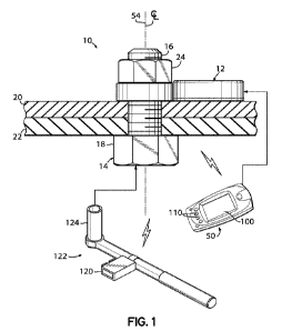
[0005] FIG. 1 depicts a system with a cross-sectional view of a typical
bolted joint
installation including an instrumented washer in accordance with the
principals of the
present disclosure.
[0006] FIG. 2 is a perspective view of the exemplary instrumented washer
of FIG.
1.
[0007] FIG. 3 is a top plan view of the washer of FIG. 2.
[0008] FIG. 4 is an exploded perspective view of the washer of FIG. 2.
[0009] FIG. 5 is a side elevation view of the washer body depicted in FIG.
4, with
cover and support platform removed for clarity.
Detailed Description
[0010] FIG. 1 depicts a typical bolted joint 10 including an exemplary
instrumented washer 12 in accordance with the principals of the present
disclosure.
The bolted joint 10 includes a threaded fastener 14 in the form of a bolt
having a
threaded shank 16 and a bolt head 18. The threaded shank 16 of the fastener 14
is
inserted through respective apertures on one or more components 20, 22 that
are to be
joined with the fastener 14. The washer 12 is also installed onto the shank
16, and may
3
CA 03162001 2022-05-18
WO 2021/104679
PCT/EP2020/050315
be located adjacent the bolt head 18 or, alternatively, adjacent a nut 24 that
is installed
onto the fastener 14. With continued reference to FIG. 1, and referring
further to
FIGS. 2-5, the exemplary washer 12 includes a generally cylindrically-shaped
annular
washer body 30 having first and second oppositely disposed axial ends 32, 34,
and an
outer circumferential sidewall 36. In one embodiment, the washer body 30 may
be
machined from a single piece of material, such as stainless steel. However, it
will be
appreciated that the washer body 30 may alternatively be formed by two or more
body
portions assembled together, and that the washer body 30 may be formed by
various
other methods suitable for producing a washer 12 that meets the requirements
for a
given application.
[0011] One
or more strain gauges 40 are disposed on the outer circumferential
sidewall 36 of the washer body 30 and may be secured to the outer
circumferential
sidewall 36, such as with adhesive or epoxy, or by any other method suitable
for affixing
the one or more strain gauges 40 to the outer sidewall 36 such that the strain
gauges 40
are able to detect deformation of the washer body 30 due to external loading,
such as
when the washer 12 is clamped in a bolted joint 10. In the embodiment shown,
the
washer 12 includes four strain gauges 40 arranged substantially symmetrically
around
the circumference of the washer body 30. In an exemplary embodiment, one or
more of
the strain gauges 40 may be configured as a Wheatstone bridge, whereby
accurate
readings of a change in resistance of the strain gauges 40 may be obtained and
the
strain gauges 40 thereby provide a robust system that is stable and less
sensitive to
variations in temperature and magnetic fields. Depending upon the number and
arrangement of strain gauges 40 then, the strain gauges 40 may be configured
in
4
CA 03162001 2022-05-18
WO 2021/104679 PCT/EP2020/050315
various forms as a quarter, half, or full Wheatstone bridge, as may be
suitable or
desired for a given application.
[0012] In another embodiment, the strain gauges 40 may additionally, or
alternatively, comprise ceramic material, whereby the operating temperature
range of
the strain gauges is sufficiently high for use in aerospace applications, such
as on
aircraft engines for example. As a non-limiting example, the operating
temperature
range of the strain gauges 40 may be higher than approximately 220 degrees
Celsius.
Additionally, or alternatively, the strain gauges 40 may be configured to have
a relatively
high operating resistance compared to conventional strain gauges. As a non-
limiting
example, the strain gauges 40 may have an operating resistance range of about
16
kiloohms to about 22 kiloohms. As a result of the high operating resistance, a
washer
12 as disclosed herein consumes very little power. Accordingly, operation of
the
washer 12 may be powered by power that is wirelessly received from an external
device, as will be described hereinbelow.
[0013] The washer 12 further includes a communication assembly 42
operatively
coupled with the at least one strain gauge 40 and configured to communicate
information related to the axial load borne by the washer 12 in the bolted
joint 10. In the
embodiment shown, the communication assembly includes an integrated circuit 44
that
is adapted to receive electrical signals from the at least one strain gauge 40
related to
the axial load of the washer 12. The communication assembly 42 may further
include
an antenna 46 for transmitting electric signals to an external device. While
the
antenna 46 is depicted herein as separate from the integrated circuit 44, the
antenna 46
may alternatively be incorporated within the structure of the integrated
circuit 44. The
CA 03162001 2022-05-18
WO 2021/104679 PCT/EP2020/050315
washer 12 may include hardwired connections between the one or more strain
gauges 40 and the integrated circuit 44, or communication between the strain
gauges 40 and the integrated circuit 44 may be carried out via wireless
communication,
as may be desired or suitable for a given application.
[0014] In one embodiment, the integrated circuit 44 may be, for example, a
model
number MLX90129 microchip available from Melexis, Inc. of Novi, Michigan, and
may
be provided on a printed circuit board 48. The integrated circuit 44 may
include a
memory for storing identification information related to the washer 12, the
bolted joint 10
installation, an installation date, a last query date, information related to
a load or force
borne by the washer 12, or various other information. The integrated circuit
44 is
configured to receive electrical signals from the one or more strain gauges 40
corresponding to loads experienced by the washer 12. The integrated circuit 44
may
convert the signals to a corresponding load value borne by the washer 12, or
the
integrated circuit 44 may transmit information to an external device, such as
a
reader 50, for subsequent processing of the information. In one embodiment,
the
integrated circuit 44 is configured to wirelessly transmit signals to an
external reader 50,
such as by radio frequency technology (RFID). Alternatively, various other
methods or
technologies may be utilized to wirelessly transmit signals and information
between the
integrated circuit 44 and an external reader 50, such as, for example,
Bluetooth, Wi-Fi,
or other technology.
[0015] The integrated circuit 44 may be configured for passive RFID,
wherein the
integrated circuit 44 receives power from an external device, such as a reader
50, when
the device is brought within range of the washer 12 when it is desired to
interrogate the
6
CA 03162001 2022-05-18
WO 2021/104679
PCT/EP2020/050315
integrated circuit 44. Upon receiving sufficient power from the external
device, the
integrated circuit 44 receives signals from the one or more strain gauges 40
and
transmits information to the reader 50 related to the load borne by the washer
12.
When the operating resistance of the strain gauges 40 is sufficiently high,
the power
received from the external device may also power the strain gauges 40, as
discussed
above. Accordingly, the washer 12 can be configured to operate without the
need for
an on-board power source, such as a battery. Alternatively, the integrated
circuit 44
may be configured for active RFID and the communication assembly 42 may
further
includes a power source, such as a battery or any other power source suitable
for self-
powering the integrated circuit 44.
[0016] In the embodiment shown, the communication assembly 42 is located
on
a support platform 52 extending radially outwardly from the washer body 30
such that
the support platform 52 is offset from an axial centerline 54 of the washer
body 30.
Such a configuration facilitates wireless communication between the washer 12
and an
external device such as a reader 50. In other embodiments, the communication
assembly 42 may be disposed within the boundary of the outer circumferential
sidewall 36 of the washer body 12, or positioned adjacent thereto. In another
embodiment, one or more of the strain gauges 40, integrated circuit 44, or
antenna 46
may be encapsulated in a polymeric material, resulting in a sealed arrangement
that
protects the electronic components of the washer 12 from the effects of
vibration or
impacts with other objects. In an exemplary embodiment, the polymeric material
is
over-molded onto the washer 12.
7
CA 03162001 2022-05-18
WO 2021/104679 PCT/EP2020/050315
[0017] In the embodiment shown, the support platform 52 comprises a
substantially circular-shaped disk 56 wherein a portion 58 of the perimeter of
the disk 56
has a radius of curvature opposite the radius of curvature of the outer
circumference of
the disk 56. This arcuate portion 58 of the perimeter is sized and shaped
complementary to the contour of the washer body 30 to facilitate joining the
support
platform 52 to the washer body 30, such as by welding or any other suitable
method.
The support platform 52 may further include a coupling wall 60 extending in an
axial
direction outwardly from the disk 56 to facilitate joining the support
platform 52 to the
washer body 30. In the embodiment shown, an aperture 62 is formed through the
coupling wall 60 to facilitate routing wires from the strain gauges 40 on the
washer body
30 to the integrated circuit 44 on the support platform 52. In one embodiment,
the
washer 12 may further include a second printed circuit board 64 disposed
between the
washer body 30 and the support platform 52 to facilitate routing electrical
connections
between the strain gauges 40 and the integrated circuit 44. For example, wires
extending from the strain gauges 40 may be electrically coupled with the
second circuit
board 64, and other wires extending from the second circuit board 64 may be
routed
through the aperture 62 in the coupling wall 60 for connection to the
integrated circuit
44.
[0018] The exemplary washer 12 may further include a protective cover 70
received over the outer circumferential sidewall 36 of the washer body 30 such
that the
one or more strain gauges 40 are enclosed between the cover 70 and the
sidewall 36.
In the embodiment shown, the washer body 30 further includes first and second
radially
outwardly extending flanges 72, 74 extending from the washer body 30 at the
first and
8
CA 03162001 2022-05-18
WO 2021/104679 PCT/EP2020/050315
second axial ends 32, 34, respectively, and the protective cover 70 may be
attached to
the washer body 30 at the first and second flanges 72, 74. For example, the
protective
cover 70 may be securely fixed at the flanges 72, 74 such as by welding, press
fit,
adhesive, or any other method suitable for securing the cover 70 to the washer
body 30.
In the same manner, the support platform 52 may be attached to the washer body
30 at
the first and second flanges 72, 74. In the exemplary embodiment shown, the
coupling
wall 60 on the support platform 52 cooperates with the cover 70 to enclose the
strain
gauges 40 on the washer body 30. While the cover 70 is shown and described
herein
as comprising a single cover section that cooperates with the coupling wall 60
to
enclose the strain gauges 40, it will be appreciated that the cover 70 may
alternatively
comprise a single cover structure that encloses the entire washer body 30, or
may
comprise two or more two sections, as may be desired.
[0019] With continued reference to FIGS. 2-5, the washer body 30 may be
further
configured with one or more flat surfaces, or facets 80, on the outer
circumferential
sidewall 36 to receive the one or more strain gauges 40. In the embodiment
shown, the
facets 80 are recessed into the outer sidewall 36 to define distinct pockets
surrounding
the facets 80 and separated by axially extending ridges 82. The ridges 82 may
facilitate
mounting the strain gauges 40 to the washer body 30, wherein the ridges 82 may
be
used as registration features to help properly locate the strain gauges 40 on
the facets
80. The exemplary washer body may further include an annular raised contact
surface
84, 86 extending axially from one or both of the first and second axial ends
32, 34. The
raised contact areas 84, 86 engage structure adjacent the washer 12 in the
assembled
bolted joint 10 and bear the load of the clamped joint. The geometry of the
first and
9
CA 03162001 2022-05-18
WO 2021/104679 PCT/EP2020/050315
second contact areas 84, 86 can be controlled to facilitate measurement and
calculation
of the load borne by the washer 12 in use.
[0020] In another embodiment, the interior of the washer body 30 includes
a
plurality of protrusions 90 extending radially inwardly from the inner
sidewall 92 to define
a plurality of axially extending channels 94 therebetween. The protrusions 90
may be
symmetrically arranged around the inner circumference of the sidewall 92 and
may be
sized and configured to facilitate a sliding fit with the shank 16 of a bolt
14 received
through the washer 12 when assembled in a bolted joint 10.
[0021] With reference again to FIG. 1, an instrumented, load-sensing
washer 12
in accordance with the principals of the present disclosure may be used in a
bolted joint
to facilitate installing and maintaining the bolted joint 10 at a desired
clamping load.
In use, the bolted joint 10 is assembled with a washer 12 in accordance with
the present
disclosure and the joint 10 is tightened with an appropriate tool. During
tightening, the
load borne by the washer 12 may be checked to determine the clamping load of
the
bolted joint 10. In one embodiment in which the washer 12 is configured for
passive
RFID communication, a reader 50, such as an M3 ORANGE+ mobile reader available
from M3 Mobile Co., Ltd. of Seoul, Korea, for example, is brought near the
washer 12
and is activated to query the washer 12 for load information. Radio frequency
signals
from the reader 50 provide power to the integrated circuit 44 as described
above. The
integrated circuit 44 then receives signals from the one or more strain gauges
40 on the
washer body 30 and transmits information wirelessly to the reader 50 related
to the load
borne by the washer 12 in the joint 10. The user may thereafter adjust the
tightness of
the bolted joint 10 based on the information. The information may also be
stored for
CA 03162001 2022-05-18
WO 2021/104679
PCT/EP2020/050315
historical record keeping or analytical purposes. The reader 50 may be
configured in
various ways to provide an indication of the load borne by the washer 12 to
the user. In
one embodiment, the reader 50 may include a visual display 100 whereby
information
related to the load borne by the washer 12 may be visually presented to the
user to
facilitate adjusting the tightness of the bolted joint 10 to obtain a desired
clamping load.
Alternatively, or in addition, the reader 50 may be configured to provide an
indication of
the load borne by the washer 12 in the form of audio signals and/or tactile
sensory
indications, such as vibrations that can be perceived by the user. The reader
50 may
further include virtual or physical buttons 110 or other input devices to
facilitate
operation of the reader 50 by a user.
[0022] In
another embodiment, a reader 120 may be integrated with a tool 122
that is configured to facilitate tightening a bolted joint 10 including a
washer 12 in
accordance with the principles of the present disclosure. In the embodiment
shown, the
tool 122 includes a fastener engaging portion 124 that is adapted to engage
the
fastener 14 when tightening (or conversely, loosening) the bolted joint 10.
The tool 122
may be configured to operate by the manual application of force by a user, or
may be
configured for automated application of force to the fastener 14, such as by a
drive
motor. The reader 120 is provided on the tool 122 and is configured to
exchange radio
frequency signals with the integrated circuit 44 during tightening, and to
provide an
indication to the user related to the load borne by the washer 12 in a manner
as
described above. The reader 120 may also be configured to store information
related to
the load for historical record keeping or analytical purposes, or to transmit
information
related to the load to other external devices or computers.
CA 03162001 2022-05-18
WO 2021/104679 PCT/EP2020/050315
[0023] In another embodiment, readers or antennae for receiving signals
from
load-sensing washers in accordance with the present disclosure may be provided
on or
integrated with the structure that is joined with the bolted joint. As a non-
limiting
example, a bolted joint including a washer in accordance with the present
disclosure
may be used to join two or more structural members in an aircraft
installation, and the
structural members, or other parts of the aircraft, may be outfitted with
suitable readers
or antennae adapted to provide power to and/or communicate with the washer to
obtain
information from the washer related to a load borne by the washer in the
bolted joint.
[0024] While the present invention has been illustrated by a description
of various
embodiments, and while these embodiments have been described in considerable
detail, it is not intended to restrict or in any way limit the scope of the
appended claims
to such detail. The various features shown and described herein may be used
alone or
in any combination. Additional advantages and modifications will readily
appear to
those skilled in the art. The invention in its broader aspects is therefore
not limited to
the specific details, representative apparatus and method, and illustrative
example
shown and described. Accordingly, departures may be made from such details
without
departing from the spirit and scope of the general inventive concept.
12