Note: Descriptions are shown in the official language in which they were submitted.
V 1
PASSIVE TUBULAR CONNECTION GUIDE
FIELD OF THE INVENTION
[001] The present disclosure relates to a guide for assisting with the end-
to-
end connection of elongated elements. In particular, the present disclosure
relates to a
guide for assisting with stabbing pin ends of tubulars into box ends of
tubulars. Still
more particularly, the present disclosure relates to a passive guide for
assisting robotic
equipment with stabbing pin ends of drill pipe into box ends of drill pipe.
BACKGROUND OF THE INVENTION
[002] The background description provided herein is for the purpose of
generally presenting the context of the disclosure. Work of the presently
named
inventor, to the extent it is described in this background section, as well as
aspects of
the description that may not otherwise qualify as prior art at the time of
filing, are
neither expressly nor impliedly admitted as prior art against the present
disclosure.
[003] Many pipe handling operations, such as drill pipe handling
operations,
are conventionally performed with workers performing manual operations. For
example, drilling of wells involves tripping of the drill string, during which
drill pipes
are lowered into (tripping in) or pulled out of (tripping out) a well.
Tripping may
typically occur in order to change all or a portion of the bottom hole
assembly, such as
to change a drill bit. Where drill pipe is tripped into a well, stands or
lengths of drill
pipe may be supplied from a storage position in a setback area of the drill
rig and
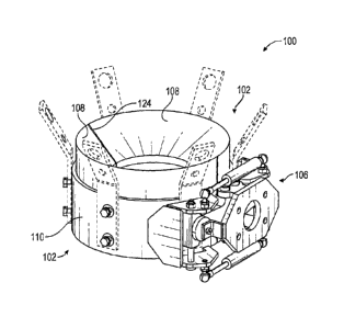
connected end-to-end to lengthen the drill string in the well. Prior to
tripping and/or
during tripping, lengths of drill pipe may also be connected end-to-end to
create pipe
stands. Where drill pipe is tripped out of a well, stands or lengths of drill
pipe may be
disconnected from the drill string and may be positioned in the setback area.
[004] As with
other pipe handling operations, tripping and, thus, the
connection of stands end-to-end has conventionally been performed with human
operators that manually place a stabbing guide. In particular, while hoisting
equipment
may be used to carry the load of a stand of drill pipe during trip in and trip
out
operations, human operators may typically maneuver the drill pipe stands
around the
drill floor, such as between the well center and the setback area. For
example, a first
human operator may be positioned on the drill floor, at or near the well, to
maneuver a
lower end of drill pipe stands as they are tripped into or out of the well,
while a second
1
CA 3162191 2022-06-09
human operator may be positioned on or above the racking board to maneuver an
upper
end of drill pipe stands as the stands are moved between the well and the
setback area.
Operators often use ropes and/or other tools to maneuver the drill pipe stands
on or
above the drill floor. The operators may also use a clam shell type guide for
helping to
guide pin ends of drill pipe into box ends of drill pipe. This guide can help
with the
alignment of the pipes. The guide may be manually moved into place on a top of
a drill
string by the deckhands. With the guide in place, a top drive elevator may,
for example,
lift a pipe stand into position above the drill string and stab the pin end of
the pipe stand
into the box end of the upper most pipe in the drill string relying on the
guide to position
.. the pin end of the pipe stand. Once the pin end of the upper pipe is
stabbed into the box
end of the lower pipe and the upper pipe is spun into the lower pipe, the
operator may
actuate a lever, for example, to open the clamshell guide and remove it from
the
connected pipes. Such work is labor-intensive and can be dangerous. Moreover,
trip
in and trip out operations may be limited by the speed at which the human
operators
can maneuver the stands between well center and the setback area.
[005] Robotic pipe handling systems may be used to handle pipe to assist
with
and/or perform the above pipe handling operations on a drill rig. The robots
may
include a series of links that are hingedly and/or pivotally connected to one
another and
perform a multitude of operations using selectable tools referred to as end
effectors.
While helpful to have a robot to assist with pipe handling, the detailed lever
actuation
on current pipe stabbing guides may be difficult for a robot to perform.
Moreover,
electrical, hydraulic, or other power may not be desirable to aid in
opening/closing a
stabbing guide. That is, while a robot may have power for moving the robot,
particular
actuation power for opening and closing a tool being used by the robot may not
be
present or desirable in the robotic drilling environment or in other
environments.
BRIEF SUMMARY OF THE INVENTION
[006] The following presents a simplified summary of one or more
embodiments of the present disclosure in order to provide a basic
understanding of such
embodiments. This summary is not an extensive overview of all contemplated
embodiments and is intended to neither identify key or critical elements of
all
embodiments, nor delineate the scope of any or all embodiments.
[007] In one or more embodiments, a guide mechanism may include a first jaw
and a second jaw pivotably coupled to the first jaw. The first and second jaws
may
2
CA 3162191 2022-06-09
form a guide having a bottom pocket adapted for seating arrangement of the
guide on a
box end of a first tubular and a top funnel configured for laterally guiding a
pin end of
a second tubular into the box end. The guide mechanism may also include a
linkage
system secured to the first and second jaws and adapted to control pivoting
motion of
the jaws. The guide mechanism may also include a bias mechanism coupled to the
linkage system and configured to impart a biasing force on the first jaw and
the second
jaw via the linkage system. The biasing force may be adapted to resist opening
of the
jaws such that opening of the jaws occurs when a lateral force is applied to
the guide
mechanism that overcomes the biasing force.
[008] In one or more embodiments, a guide mechanism may include a first jaw
and a second jaw pivotally coupled to the first jaw at a pivot point and
forming a tubular
connection guide. The guide mechanism may also include a pair of main links
pivotally
coupled to one another at a central location outside the first and second jaw
and
proximate the pivot point. The pair of main links may extend away from the
central
location and along respective first and second jaws to respective free ends.
The free
ends may be pivotally coupled to the first jaw and the second jaw,
respectively, at first
and second outer pivot points. The guide mechanism may also include a biasing
mechanism resistant to compression and arranged between the first and second
outer
pivot points.
[009] In one or more embodiments, a method of guiding a tubular connection
may include placing a guide on a box end of a first tubular and seating the
box end in a
bottom pocket of the guide. The method may also include suspending a second
tubular
above the first tubular and lowering a pin end toward the box end. The method
may
also include guiding the pin end with the guide into the box end and pulling
the guide
laterally off of the first and second tubular, wherein pulling of the guide in
a lateral
direction opens the guide. As the stabbing guide clears the tubulars, it may
close based
on a biasing force so as to prepare for a next placement.
[010] While multiple embodiments are disclosed, still other
embodiments of
the present disclosure will become apparent to those skilled in the art from
the following
detailed description, which shows and describes illustrative embodiments of
the
invention. As will be realized, the various embodiments of the present
disclosure are
capable of modifications in various obvious aspects, all without departing
from the
spirit and scope of the present disclosure. Accordingly, the drawings and
detailed
description are to be regarded as illustrative in nature and not restrictive.
3
CA 3162191 2022-06-09
BRIEF DESCRIPTION OF THE DRAWINGS
[011] While the specification concludes with claims particularly pointing
out
and distinctly claiming the subject matter that is regarded as forming the
various
embodiments of the present disclosure, it is believed that the invention will
be better
understood from the following description taken in conjunction with the
accompanying
Figures, in which:
[012] FIG. 1 is an elevation view of a drill rig having a robotic system
and a
passive tubular connection guide, according to one or more embodiments.
[013] FIG. 2 is a perspective view of a passive tubular connection guide
with
a passive rotation disconnect for selectively securing the guide to a robotic
arm,
according to one or more embodiments.
[014] FIG. 3 is a perspective view of a passive tubular connection guide,
according to one or more embodiments.
[015] FIG. 4 is a top view thereof.
[016] FIG. 5 is a top view thereof with the guide in an open condition.
[017] FIG. 6 is a rear view thereof.
[018] FIG. 7 is a side view thereof.
[019] FIG. 8 is a perspective view of a bracket and a liner portion,
according
to one or more embodiments.
[020] FIG. 9 is a transparent view of a liner portion, according to one or
more
embodiments.
[021] FIG. 10 is a breakaway view of a core within a liner, according to
one
or more embodiments.
[022] FIG. 11 is a front side perspective view of a linkage system,
according
to one or more embodiments, where the semicircular plates of the brackets have
been
omitted for clarity.
[023] FIG. 12 is a back side perspective view of a linkage system,
according
to one or more embodiments.
[024] FIG. 13 is a top view of the linkage system in a closed condition,
according to one or more embodiments.
[025] FIG. 14 is a top view of the linkage system in an open condition,
according to one or more embodiments.
4
CA 3162191 2022-06-09
1
[026] FIG. 15 is a cross-sectional view of the linkage system, according to
one
or more embodiments.
[027] FIG. 16A is a perspective view of the passive tubing guide in place
on a
pipe string poised to receive a pipe or pipe stand, according to one or more
embodiments.
[028] FIG. 16B is a perspective view of the passive tubing guide in place
on a
pipe string and receiving the pipe or pipe stand, according to one or more
embodiments.
[029] FIG. 16C is a perspective view of the passive tubing guide in a
partially
removed state, according to one or more embodiments.
[030] FIG. 16D is a perspective view of the passive tubing guide in a fully
removed state, according to one or more embodiments.
[031] FIG. 17 is a diagram depicting a method of use of the passive
tubular
connection guide, according to one or more embodiments.
DETAILED DESCRIPTION
[032] The present disclosure, in one or more embodiments, relates to
devices,
systems, and methods for guiding the connection of tubulars. In particular, a
passive
tubular connection guide may be provided that is particularly adapted for use
without a
power source to open and close the guide. For example, the passive tubular
connection
guide may be used without compressed air, hydraulic power, electric power, or
other
power source for opening and closing the guide. Rather, a robot, user, tool
arm, or other
manipulating device or system may operate the guide in a manner that allows
for
opening and closing of the guide simply by motion of the guide relative to the
tubulars.
In the context of well drilling, this approach to a tubular connection guide
may obviate
the need for hydraulic lines, electrical lines, air lines, or other power-
providing cords
that may otherwise be draped across the drill floor, not to mention obviating
the need
for a hydraulic pump, generator, compressor, or other energy source.
[033] FIG. 1 is an elevation view of a drill rig 50 having a robotic
system and
a passive tubular connection guide 100, according to one or more embodiments.
As
shown, the drill rig 50 may include a support structure 52 supporting a drill
floor 54
and a mast 56. The drill rig 50 may include a racking board 58 extending
laterally from
the mast 56 and robotic handlers 64a/b may be arranged on the drill floor 54
and the
racking board 58. The drill rig 50 may include a top drive 60 with a pipe
elevator 62.
As described in more detail below, the top drive 60, top drive elevator 62 and
the robotic
5
CA 3162191 2022-06-09
handlers 64a/b may operate in a coordinated tripping process to trip drill
pipe or other
tubulars 66 into and out of a well bore. In one or more embodiments, the
robotic
handlers 64a/b may rely on interchangeable tools that may be selectively
secured to the
ends of the robotic arms to allow the robotic handlers 64a/b to perform
particular
operations in the process.
[034] As shown in FIG. 2, for example, a passive tubular connection guide
100 may be bolted or otherwise secured to a tool portion 68 of a remote
connection
interface 74 such as a passive rotation disconnect and may be stationed in a
saddle or
other holder 70. The robotic handler 64a may have a proximal portion 72 of the
remote
connection interface 74 secured thereto. The robotic handler 64a may use the
remote
connection interface 74 to selectively pick up or set down the passive tubular
connection guide 100. Operation of the remote connection interface 74 and the
guide
100 may be performed without the need for external power extending to them.
One
example of a remote connection interface 74 may be a passive rotation
disconnect and
may be the same or similar to the device described in International Patent
Application
PCT/US2021/070488 entitled Passive Rotation Disconnect and filed on April 30,
2021,
the content of which is hereby incorporated by reference herein in its
entirety.
[035] As discussed in more detail below, the robotic handler 64a may use
the
passive tubular connection guide 100 to assist with tripping operations by
guiding a
free end of a suspended tubular into a box end of a drill string extending
into a well
bore. While the passive tubular connection guide 100 has been described as
being used
by a robotic system, this discussion is simply for purposes of providing one
example
use of the passive tubular connection guide 100 and nothing in the present
application
shall foreclose other uses of the passive tubular connection guide 100
including manual
use. Moreover, while the passive tubular connection guide 100 has been
discussed in
the context of drilling tubulars, the passive tubular connection guide 100 may
be used
in other contexts as well where, for example, end-to-end connection of
tubulars is being
performed.
[036] FIG. 3 is a perspective view of a passive tubular connection guide
100,
according to one or more embodiments. The passive tubular connection guide 100
may
be configured for placement over a box end 76 of a pipe in a drill string and
further
configured for guiding a pin end 78 of another pipe into the box end 76. (see
FIGS.
16a-16d) The passive tubular connection guide 100 may be further configured
for
lateral removal from the connected tubulars 66 after guiding and preliminary
6
CA 3162191 2022-06-09
connection of the tubulars 66 is complete. As shown in FIGS. 3-7, the passive
tubular
connection guide 100 may include first and second jaws 102 coupled to one
another
with a pivot mechanism 104 (see FIG. 5) and a linkage system 106 may also be
provided.
[037] The first
and second jaws 102 may be adapted to open and close in
clamshell fashion. Each of the jaws 102 may form opposing portions or halves
of the
guide 100 and, together, may be adapted for seated arrangement on a box end 76
of a
pipe or tubular 66 and for funnel-like guiding of a pin end 78 into the box
end 76. As
shown, the jaws 102 may each include a liner portion 108 and a bracket 110.
When the
jaws 102 are closed, the liner portions 108 may, together, form a liner and
the brackets
110 may, together, form a collar.
[038] With reference to FIGS. 3-7, the brackets may be configured to
provide
an interface between the linkage system 106 and the first and second jaws 102.
As
shown in FIG. 8, the bracket 110 of each jaw 102 may include a substantially
semi-
circular element or plate having an outer radius 112 and an inner radius 114
where the
difference between the outer and inner radius defines a thickness 116. The
plate may
have a height 118 extending between top and bottom semi-annular surfaces
120/122.
In one or more embodiments, the substantially semi-circular plates may stop
short of a
hinge or pivot point on one side of the guide 100 and a seam or joint 124 on
an opposite
side of the guide 100. The brackets 110 may also have a linkage interface 172
which
is discussed in more detail below in conjunction with the linkage system 106.
[039] With continued reference to FIG. 8, the liner portion 108 of each jaw
102 is shown. The liner portion 108 may be configured for physically
interacting,
together with a corresponding liner portion 108, with a box end 76 and a pin
end 78 of
a set of tubulars that are to be joined and for guiding the pin end 78 into
the box end
76. As shown, the liner portion 108 may include a substantially thick and semi-
circular
body portion 126 having an outer surface 128 adapted for engagement by a
respective
bracket 110. That is, for example, the outer surface 128 may be a
substantially radiused
surface having a radius 130 the same or similar to the radius 114 of the
inside surface
of the bracket 110. The outer surface 128 may have a height 132 extending
between a
bottom edge 134 and a top edge 136. The liner portion 108 may include a bottom
semi
annular surface 138 having an outer edge coinciding with the bottom edge 134
of the
outer surface and defined by the radius 130 of the outer surface 128. The
bottom semi
annular surface 138 may also have an inner edge 140 defined by a radius 142
7
CA 3162191 2022-06-09
substantially smaller than the radius 130 of the outer surface 128, thus,
defining a
substantially thick wall of the body portion 126. The radius 142 of the inner
edge 140
may be selected to be slightly larger, but similar in size to an outer radius
of a box end
76 of a selected size of drill pipe or other tubular 66. An inner semi
cylindrical wall
144 may extend upward from the inner edge 140 defining one half of a bore or
bottom
pocket extending upward from the bottom surface 138 and into the body portion
126.
When placed adjacent another same or similar liner portion 108, the two may
form the
full bore or bottom pocket on a bottom side of the guide 100. In one or more
embodiments, the inner semi cylindrical wall 144 may extend upward from the
bottom
a distance ranging between approximately 1/3 and 7/8 of the height 132 of the
body
portion 126 or between approximately 1/2 and % of the height 132 of the body
portion
126, or approximately 2/3 of the height 132 of the body portion 126. A lip,
catch, rib,
or other protrusion 146 may be provided at the top of the inner semi
cylindrical wall
144, which may function to allow the guide 100 to rest on a box end 76 of a
tubular 66.
The protrusion 146 may extend radially inward relative to the semi cylindrical
wall 144
forming an annular stop surface 148. The annular stop surface 148 may have an
inner
edge 150 defined by a radius 152. The radius 152 may be selected to be smaller
than
the radius 142 of the inner semi-cylindrical wall 144, but larger than a pin
end 78 of a
tubular 66 such that the pin end 78 may pass through the guide 100 and into a
box end
76 of a lower tubular 66. The inner edge 150 of the annular stop surface 148
may give
way to a chamfered edge 154 in the form of a semi cylindrical inner ribbon
with a radius
the same as the inner edge 150 of the annular stop surface 148 and extending a
short
distance upward from the annular stop surface 148 to a relief edge 156. The
remaining
height of the inner portion of the body portion 126 may include a diverging
surface 158
that extends upward from the relief edge 156 at an angle= to meet the top edge
136 of
the outer surface 128 at a semi-circular edge that forms a semi peripheral
point around
the top of the liner portion 108. When placed adjacent another liner portion
108 with a
same or similar shape, the diverging surfaces 158 of the two liner portions
108 may
form a conical or funnel shaped guide for physically guiding a pin end 78 of
the tubular
66 to the center of the guide 100 and into a box end 76 of a lower tubular 66.
[040] In one or more embodiments as shown in FIG. 9, the liner
portion 108
may be reinforced with an internal core 160. The internal core 160 may be
molded
within the liner portion 108 to stiffen or reinforce the liner portion 108. As
shown, the
internal core 160 may include a semi-circular plate similar to the bracket
110, but
8
CA 3162191 2022-06-09
having smaller radii such that the internal core 160 fits within the liner
portion 108. In
one or more embodiments, the liner portion may be injection molded,
overmolded, or
otherwise formed around the internal core 160. As shown, the internal core 160
may
include a hinge component 162 or other pivoting component on one end thereof
that is
arranged to extend out of one side of the liner portion 108 so as to engage a
hinge
component 162 or other pivoting component on an opposing inner core 160. The
hinge
component 162 on each of two adjacent internal cores 160 may be secured to one
another with a hinge pin to create the pivot mechanism 104 (see FIG. 5) for
the two
liner portions 108 and to establish a pivot axis about which the two liner
portions 108
may pivot between an open condition (see FIG. 5) and a closed condition (see
FIG. 4).
The internal core 160 may also provide for a strong internal structure for
attaching the
brackets 110 to the liner portions 108. For example, as shown in FIG. 10,
bolts or other
fasteners 164 may extend from outside the bracket 110, through the bracket,
into the
liner portion 108 and threadingly engage bores in the core plate 160 so as to
pull or
press the bracket against the liner portion 108. In one or more embodiments,
pipe
doping brackets 166 may be included as part of this connection.
[041] With the jaws 102 described, the linkage system 106 that controls or
manages the opening and closing operation of the jaws 102 may be described.
That is,
the linkage system 106 may be adapted to maintain the jaws 102 in a closed
condition
unless/until a sufficient radial force acting radially and/or generally
parallel to a the
joint 124 between the free ends of the jaws 102 is sufficient to overcome a
biasing
closing force. As shown in FIGS. 11-15, the linkage system 106 may include a
central
bracket 168, a pair of main links 170, a biasing mechanism 174, and a detent
mechanism
176. As mentioned above, the brackets 110 may include a linkage interface 172
for
interfacing with the linkage system. Each of these parts may be taken in turn.
It is
noted that the semicircular plate portions of the brackets 110 in FIG. 11 have
been
omitted to allow for better viewing of the linkage system 106.
[042] The central bracket 168 may be adapted to provide a grasping or
mounting location for a user. For example, as shown in FIG. 2, the central
bracket 168
may include a back plate 178 with a bolt pattern adapted for securing the
guide 100 to
a remote connection interface 74, directly to a robot arm, directly to a tool
arm, or for
securing another operable element. In one or more embodiments, a handle or
other
gripping device may be provided extending from the back plate 178. The central
bracket 168 may also be configured to provide a common location for securing
the pair
9
CA 3162191 2022-06-09
of main links 170 such that operation of the links 170 is relative to one
another and
relative to the central bracket 168. As shown, the central bracket 168 may
include a
top bracket plate 180 and a bottom bracket plate 182 each extending toward the
jaws
102 from the back plate 178 (e.g., opposite the back plate connection to a
tool arm or
remote connection interface). The top and bottom bracket plates 180/182 may be
adapted for securing the pair of main links 170 to the central bracket 168. As
shown, a
base end of each link 170 may be placed between the top and bottom brackets
180/182
and a bolt, pin, or other elongate element 171 may be arranged through the top
and
bottom brackets 180/182 and through the base end of each respective link 170.
The
elongate elements 171 may be substantially adjacent one another and may
establish
pivot axes for the main links 170. The pivot axes may extend parallel to one
another
such that pivoting motion of the main links 170 is parallel to one another and
since the
main links 170 are arranged between shared top and bottom brackets 180/182,
the
pivoting motion of the pivot links 170 may also be in a same plane.
[043] The pair of main links 170 may extend from their pivoting connection
to the central bracket 168 generally laterally and in opposite directions
along respective
brackets 110. The pair of main links 170 may be configured to pivot relative
to the
central bracket 168 between a relatively flat configuration where each link is
extending
in substantially opposite directions and a more v-shaped configuration where
each link
170 is extending partially in opposite directions but also in a direction
toward the liner
108. In the former condition of the links 170, the jaws 102 of the guide 100
may be
closed and in the latter condition of the links 170, the jaws 102 of the guide
100 may
be open.
[044] The links may be secured to the brackets 110 at a linkage
interface 172
on the brackets 110. The linkage interface 172 may be part of respective
brackets 110
and may be configured for establishing a pivoting connection between the free
ends of
the links 170 and the bracket 110 of each jaw 102. The linkage interface 172
may also
provide an attachment point for one or more biasing mechanisms 174. As shown,
the
linkage interface 172 may include upper and lower plates 184/186 secured to
one
another by a closure plate 188 extending between the outboard edges of the
upper and
lower plates 184/186. The closure plate 188 may extend forward toward the
semicircular plate of the bracket 110 and may include a nose 190 formed from
upper
and lower chamfered forward corners of the closure plate 188. The nose 190 of
the
closure plate may be secured to the semicircular plate portion of the bracket
110. As
CA 3162191 2022-06-09
shown in FIGS. 13 and 14, the upper and lower plates 184/186 may have a
generally
flat front edge and a segmented back edge to provide connection points for the
links
170 and the biasing mechanism 174. That is, the linkage interface 172 may be
sized to
receive the free end of the main links 170 between the upper and lower plates
184/186
and an elongate element 171 may extend through the upper and lower plates
184/186
and through the free end of the main link 170 to establish a substantially
vertical axis
about which the linkage interface 172 may rotate relative to the main link
170. On a
central bracket side of the elongate element, a biasing mechanism 174 may be
secured
to each of the upper and lower plates 184/186. The upper and lower plates
184/186
may each include an inner thumb, tab, or standoff 192 secured to the
semicircular plate
portion of the bracket.
[045] The biasing mechanism 174 may extend laterally across the
linkage
system 106. As shown, a biasing mechanism 174 may extend between each of the
upper plates 184 and another biasing mechanism 174 may extend between each of
the
lower plates 186. The biasing mechanism 174 may be biased toward an extended
position as shown in FIG. 13. In one or more embodiments, the biasing
mechanism
may be in the form of spring cylinders, or another type of biasing mechanism
may be
provided. In one or more embodiments, the biasing mechanisms on the top and
bottom
of the linkage 106 may be oriented oppositely as shown.
[046] One or more detent mechanisms 176 may be arranged to extend from
the central bracket 168 and may be adapted to hold the main links 170 in a
generally
straight (e.g., extending in substantially opposite directions) condition
unless/until a
force is present to release the detent. In one or more embodiments, the detent
mechanism 176 may include one or more magnets extending off of the sides of
the back
plate 178 of the central bracket 168 via brackets 194. That is, as shown in
FIG. 15, a
bracket 194 such as an L-bracket may be provided on either side of the back
plate 178
providing a mounting surface for a magnet that may face the back side of a
respective
main link 170. As shown in FIG. 15, when the guide 100 in a closed condition,
the
magnet may be pressed against or arranged in close proximity to a back side of
the main
link 170 and, as such, may function to hold the main link 170 in a
substantially straight
condition extending substantially opposite the direction of the other main
link 170.
Magnets may be provided on each side of the central bracket 168 and, as such,
both
main links 170 may be held. Unless or until the magnet force is overcome and
sufficient
separation between the magnet and the main links 170 is present, the magnet
may
11
CA 3162191 2022-06-09
exhibit a detent force functioning to hold the linkage 106 in the closed
condition. In
one or more embodiments, the magnets may be omitted and a stronger biasing
force
may be used in lieu of a detent mechanism. In still other embodiments, the
main links
may move passed center to create a detent force.
[047] As shown in the cross-section of FIG. 15, the linkage system 106 may
have an overall arrangement in the shape of a diamond formation 196 having
hinges or
pivot points on all comers and a biasing mechanism 174 extending from one
comer to
an opposite corner thereby biasing the diamond formation 196 in an elongated
condition. However, upon pulling in opposite directions on the corners of the
diamond
formation not having the biasing mechanism 174, the biasing mechanism 174 may
be
compressed allowing the diamond formation 196 to be less elongate unless/until
the
pulling force is released. As shown, two of the four sides of the diamond
formation
196 may include the pair of main links 170. The other two sides of the diamond
formation 196 may each be made up, collectively, of a linkage interface 172
and a liner
-- portion 108. The pair of main links 170 may be pivotally coupled to one
another at a
substantially common point at the central bracket 168. The liner portions 108
may be
pivotally coupled to one another at the pivot mechanism 104. The linkage
interface
172 and liner portion 108 may each be pivotally coupled to respective main
links 170
at the linkage interface 172. The biasing mechanism 174 may extend across the
.. diamond formation 196 between the free ends of the main links 170. Notably,
the
features of the guide 100 are arranged such that widening out or reduction of
the
elongate nature of the diamond formation 196 also opens the jaws 102.
Moreover, the
lateral extension of the central bracket 168 may be such that the detention
mechanism
176 engages the diamond formation 196 at or near the free ends of the main
links 170.
.. Holding the free ends of the links 170 against relative rotation to the
central bracket
168 may resist opening of the diamond formation 196 and doing so at or near
the free
ends of the links 170, provides a relatively high level of resistance to
rotation of the
main links 170 due to the engagement of the links 170 at a relatively large
distance
from their common pivot point. The central bracket 168 and detention magnets
may,
-- thus, function as a splint along an elongated side of the diamond formation
196.
[048] In view of the above, one example guide mechanism may be
described
a bit differently as including a first jaw 102 and a second jaw 102 pivotally
coupled to
the first jaw 102 at a pivot point 104 and forming a tubular connection guide
100. The
guide mechanism may also include a pair of main links 170 pivotally coupled to
one
12
CA 3162191 2022-06-09
another at a central location outside the first and second jaw 102 and
proximate the
pivot point 104. That is, the jaws 102, when closed may have an inside portion
for
handling tubulars and an outside portion outside the clamping region of the
jaws 102.
So, the central location may be central to the pair of main links 170, but may
be outside
of the clamping region of the jaws 102 and near the pivot point 104 of the
jaws. The
pair of main links 170 may extend away from the central location and along
respective
first and second jaws 102 to respective free ends. The free ends may be
pivotally
coupled to the first jaw 102 and the second jaw 102, respectively, at first
and second
outer pivot points. That is, while the linkage interfaces 172 have been
described as
being secured to the semicircular plate and pivotally coupled to the links
170, here, we
are simply saying the free ends of the links 170 may be pivotally coupled to
the jaws
102 in some way and we have suggested this location be termed the outer pivot
points.
This could very well be the pivot connection between the linkage interfaces
172 and
the links 170, but another outer pivot point may also be provided. Moreover,
as
described here, a portion of each jaw 102 and the pair of main links 170, may,
thus,
form a diamond formation 196. The example guide mechanism may also include a
biasing mechanism 174 resistant to compression and arranged between the first
and
second outer pivot points. In one or more embodiments, the example guide
mechanism
may also include a detent mechanism 176 adapted to hold the pair of main links
170 in
a generally parallel arrangement. That is, as shown in FIG. 15, for example,
when the
diamond formation 196 is elongated, the pair of main links 170 may extend in
almost
exactly opposite directions and, as such, be generally parallel. In one or
more
embodiments, the detent mechanism 176 may include a central bracket 168 and a
pair
of magnets arranged at or near the outer pivot points. In still further
embodiments, the
central bracket 168 may be adapted for engagement by a tool arm.
[049] In
operation and use, the present guide may be used for tripping drill
pipe into a well or otherwise accommodating the stabbing of tubular
connections while
protecting relatively delicate surfaces such as pipe threads, for example.
That is, with
reference to FIG. 1, a robotic handler 64b at the racking board 58 may grasp a
top
portion of a tubular 66 with an end effector and may tip the tubular 66 to
deliver a top
portion of the tubular to the top drive elevator 62. The top drive elevator 62
may grasp
the top of the tubular 66 and lift the tubular 66 while the robotic handler
64a at the drill
floor 54 grasps the bottom of the tubular 66 with an end effector and guides
the bottom
of the tubular 66 as it swings toward well center. The drill string in the
well bore may
13
CA 3162191 2022-06-09
have a top end that stops a short distance above the drill floor 54 and,
having retrieved
another tubular 66, the top drive elevator 62 may suspend the tubular 66 above
and
generally in line with the drill string. The robotic handler 64a at the drill
floor 54 may
replace its end effector with a passive tubular connecting guide 100 by
placing the end
effector in a stand and releasing the end effector using a remote connection
interface
74, such as a passive rotation disconnect, and engaging the tubing guide 100
using a
the remote connection interface 74. That is, and as shown in FIG. 2, the
passive tubular
connection guide 100 may be bolted or otherwise secured to a remote connection
interface 74 and may be positioned in a stand or holder. The robotic handler
64a may
have a robot portion configured for engaging the remote connection interface
74
secured to an end of a manipulator arm. The remote connection interface 74 may
allow
the robot to passively retrieve a variety of different tools.
[050]
With the passive tubular connection guide 100 secured to its arm, the
robotic handler 64a may perform a method 200 of guiding a tubular connection
as
shown in FIG. 17 and as portrayed in FIGS. 16a-16b. However, a manual user or
other
operator may also perform this method 200 and nothing shall be construed to
require
robotics for operation of the guide 100. As shown in FIG. 16a, the passive
tubular
connection guide 100 may be arranged above the drill string and below the
suspended
tubular (202), aligned with the top of the drill string (204), and lowered
onto the drill
string (206). As shown in FIG. 16b, the bottom pocket of the guide 100 may
nestle or
seat onto the box portion 76 of the tubular 66. The top drive may then lower
the
suspended tubular (208) relying on the guide 100 to guide the pin end 78 of
the
suspended tubular 66 into a box end 76 of the drill string. The top drive may
spin the
suspended tubular 66 to threadingly engage the suspended tubular 66 with the
drill
string (210) thereby preliminarily securing the tubular 66 to the drill
string. In one or
more embodiments, the spinning may be performed before removing the guide 100
or
the guide may be removed before the spinning operation. The robotic handler
64a or
other user may then pull the passive tubular connection guide 100 off of the
now
coupled, preliminarily coupled, or stabbed tubulars (212). As shown in FIG.
16c, the
pulling of the guide 100 off of the tubulars 66 may generate a lateral force
on the guide
100 extending generally away from the linkage 106 and passing generally
through the
seam 124 between the free ends of the jaws 102. The circular surface of the
tubular 66
may cause this force to result from two radially extending loads on the tips
of the jaws
102. Under this force, which acts generally orthogonally to the biasing
mechanisms
14
CA 3162191 2022-06-09
across the diagonal formation 196, the detent force and the biasing force may
be
overcome and the guide 100 may open and compress the biasing mechanism 174
generating a compressive force therein (214). The opening of the guide 100 may
free
the guide up to be removed laterally from the now extended drill string as
shown in
FIG. 16c (216). As the guide is removed from the drill string, the tubular may
maintain
separation between the free ends of the jaws 102 and maintain the compressive
force in
the biasing mechanism 174. As shown in FIG. 16d, upon pulling the guide free
from
the tubulars 66, the resistance to the compressive force in the biasing
mechanism 174
may be removed and the biasing mechanism 174 may extend thereby drawing the
free
ends of the jaws 102 back together again and into the closed position (218).
[051] As used herein, the terms "substantially" or "generally" refer to the
complete or nearly complete extent or degree of an action, characteristic,
property,
state, structure, item, or result. For example, an object that is
"substantially" or
"generally" enclosed would mean that the object is either completely enclosed
or nearly
completely enclosed. The exact allowable degree of deviation from absolute
completeness may in some cases depend on the specific context. However,
generally
speaking, the nearness of completion will be so as to have generally the same
overall
result as if absolute and total completion were obtained. The use of
"substantially" or
"generally" is equally applicable when used in a negative connotation to refer
to the
complete or near complete lack of an action, characteristic, property, state,
structure,
item, or result. For example, an element, combination, embodiment, or
composition
that is "substantially free of' or "generally free of' an element may still
actually contain
such element as long as there is generally no significant effect thereof
[052] To aid the Patent Office and any readers of any patent issued on this
application in interpreting the claims appended hereto, applicants wish to
note that they
do not intend any of the appended claims or claim elements to invoke 35 U.S.C.
112(f)
unless the words "means for" or "step for" are explicitly used in the
particular claim.
[053] Additionally, as used herein, the phrase "at least one of [X] and
[Y],"
where X and Y are different components that may be included in an embodiment
of the
present disclosure, means that the embodiment could include component X
without
component Y, the embodiment could include the component Y without component X,
or the embodiment could include both components X and Y. Similarly, when used
with
respect to three or more components, such as "at least one of [X], [Y], and
[Z]," the
phrase means that the embodiment could include any one of the three or more
CA 3162191 2022-06-09
components, any combination or sub-combination of any of the components, or
all of
the components.
[054] In the foregoing description various embodiments of the
present
disclosure have been presented for the purpose of illustration and
description. They are
not intended to be exhaustive or to limit the invention to the precise form
disclosed.
Obvious modifications or variations are possible in light of the above
teachings. The
various embodiments were chosen and described to provide the best illustration
of the
principals of the disclosure and their practical application, and to enable
one of ordinary
skill in the art to utilize the various embodiments with various modifications
as are
suited to the particular use contemplated. All such modifications and
variations are
within the scope of the present disclosure as determined by the appended
claims when
interpreted in accordance with the breadth they are fairly, legally, and
equitably entitled.
16
CA 3162191 2022-06-09