Note: Descriptions are shown in the official language in which they were submitted.
WO 2021/167922
PCT/US2021/018284
POSITION ASSISTANCE SYSTEM FOR A MATERIALS HANDLING
VEHICLE
TECHNICAL FIELD
[0001] The present embodiments relate to a materials handling
vehicle having a
positioning assistance system that provides assistance to an operator that is
driving the
vehicle.
BACKGROUND ART
[0002] Known materials handling vehicles include a power
unit, a mast assembly,
and a platform assembly that includes a fork carriage assembly coupled to the
mast
assembly for vertical movement relative to the power unit.
DISCLOSURE OF INVENTION
[0003] In accordance with a first aspect, a materials
handling vehicle comprises a
power unit; a load handling assembly; and a positioning assistance system that
provides assistance to an operator that is driving the vehicle. The assistance
provided
by the positioning assistance system comprises at least one of an audible,
tactile, or
visual cue to indicate at least one of: a distance from the vehicle to a
boundary object;
or a heading of the vehicle with respect to the boundary object.
[0004] The at least one of the audible, tactile, or visual
cue may be actuated by the
positioning assistance system to indicate at least one of: the vehicle is
located at a
distance that is equal to or greater than a desired distance from the boundary
object; or
the vehicle is located at a proper heading with respect to the boundary
object.
[0005] The at least one of the audible, tactile, or visual
cue may be actuated by the
positioning assistance system to indicate at least one of: the vehicle is not
located at a
distance that is equal to or greater than a desired distance from the boundary
object; or
the vehicle is not located at a proper heading with respect to the boundary
object.
[0006] The at least one of the audible, tactile, or visual
cue may comprise first and
second cues. The first cue may be actuated by the positioning assistance
system when
at least one of: the vehicle is located at a distance that is equal to or
greater than a
desired distance from the boundary object; or the vehicle is located at a
proper
heading with respect to the boundary object. The second cue may be actuated by
the
positioning assistance system when at least one of: the vehicle is not located
at a
1
CA 03163133 2022- 6- 27
WO 2021/167922
PCT/US2021/018284
distance that is equal to or greater than the desired distance from the
boundary object;
or the vehicle is not located at a proper heading with respect to the boundary
object.
The first cue may be distinguishable from the second cue.
[0007] The at least one of the audible, tactile, or visual
cue may comprise a visual
cue. The visual cue may be actuated by the positioning assistance system on at
least
one of: a display device; or a floor surface in front of the vehicle and to a
right side
thereof, and the visual cue may be provided to indicate that the vehicle must
be
steered to the right to be located at least one of: a distance that is equal
to or greater
than a desired distance from the boundary object; or at a proper heading with
respect
to the boundary object. Additionally or alternatively, the visual cue may be
actuated
by the positioning assistance system on at least one of: the display device;
or the floor
surface in front of the vehicle and to a left side thereof, and the visual cue
may be
provided to indicate that the vehicle must be steered to the left to be
located at least
one of: a distance that is equal to or greater than the desired distance from
the
boundary object; or at the proper heading with respect to the boundary object.
100081 The assistance provided by the positioning assistance
system may further
comprise at least one of an additional audible, tactile, or visual cue to
indicate at least
one of: a distance from the vehicle to a second boundary object; or a heading
of the
vehicle with respect to the second boundary object. The at least one of the
audible,
tactile, or visual cue may be distinguishable from the at least one of the
additional
audible, tactile, or visual cue. When the vehicle is located at both of: a
distance that is
equal to or greater than a desired distance from the first and second boundary
objects;
and at a proper heading with respect to the first and second boundary objects,
the
vehicle may be able to be remotely controlled by an operator using a remote
control
device. When the vehicle is not located at least one of: a distance that is
equal to or
greater than the desired distance from at least one of the first and second
boundary
objects; or the proper heading with respect to at least one of the first and
second
boundary objects, the vehicle may not be able to be remotely controlled by an
operator using the remote control device.
[0009] The boundary object may comprise a first boundary
object located on a
right side of the vehicle, and the at least one of the audible, tactile, or
visual cue may
comprise first, second, and third cues. The first cue may be actuated by the
positioning assistance system when at least one of: the vehicle is located at
a distance
that is equal to or greater than a desired distance from both the first
boundary object
2
CA 03163133 2022- 6- 27
WO 2021/167922
PCT/US2021/018284
and a second boundary object located on a left side of the vehicle; or the
vehicle is
located at a proper heading with respect to both the first boundary object and
the
second boundary object. The second cue may be actuated by the positioning
assistance system when at least one of: the vehicle is not located at a
distance that is
equal to or greater than the desired distance from the first boundary object;
or the
vehicle is not located at a proper heading with respect to the first boundary
object.
The third cue may be actuated by the positioning assistance system when at
least one
of: the vehicle is not located at a distance that is equal to or greater than
the desired
distance from the second boundary object; or the vehicle is not located at a
proper
heading with respect to the second boundary object. The first, second, and
third cues
may be distinguishable from one another.
100101 The boundary object may comprise a wall or a storage
structure.
100111 In accordance with a second aspect, a method is
provided for operating a
materials handling vehicle. At least one of: a distance from the vehicle to at
least one
boundary object; or a heading of the vehicle with respect to the at least one
boundary
object, is determined. Assistance is provided via a positioning assistance
system on
the vehicle to an operator that is driving the vehicle. The assistance
comprises the
positioning assistance system providing at least one of an audible, tactile,
or visual
cue to indicate at least one of: the vehicle is located at a distance that is
equal to or
greater than a desired distance from the at least one boundary object; the
vehicle is
located at a proper heading with respect to the at least one boundary object;
the
vehicle is not located at a distance that is equal to or greater than the
desired distance
from the at least one boundary object; or the vehicle is not located at the
proper
heading with respect to the at least one boundary object.
100121 The assistance provided by the positioning assistance
system may
comprise providing at least one of: an audible, tactile, or visual first cue
if the distance
from the vehicle to the at least one boundary object is less than the desired
distance;
or an audible, tactile, or visual second cue if the vehicle is not located at
the proper
heading with respect to the at least one boundary object. The assistance
provided by
the positioning assistance system may further comprise providing an audible,
tactile,
or visual third cue distinguishable from the first and second cues to indicate
that the
vehicle is at least one of located at a distance that is equal to or greater
than the
desired distance from the at least one boundary object; or oriented at the
proper
heading with respect to the at least one boundary object.
3
CA 03163133 2022- 6- 27
WO 2021/167922
PCT/US2021/018284
[0013] The at least one boundary object may comprise a first
boundary object
located on a left side of the vehicle and a second boundary object located on
a right
side of the vehicle. The at least one of the audible, tactile, or visual cue
may be
provided to indicate at least one of: the distance from the vehicle to the
first boundary
object is less than the desired distance; or the distance from the vehicle to
the second
boundary object is less than the desired distance. Only once the vehicle is
located at a
distance that is equal to or greater than the desired distance from the first
and second
boundary objects, and the vehicle is oriented at the proper heading with
respect to the
first and second boundary objects, the vehicle may be permitted to be remotely
controlled by the operator using a wireless remote control device.
[0014] The at least one boundary object may comprise a first
boundary object
located on a left side of the vehicle and a second boundary object located on
a right
side of the vehicle. The at least one of the audible, tactile, or visual cue
may comprise
a visual cue and may be actuated by the positioning assistance system on at
least one
of: a display device; or a floor surface in front of the vehicle and to the
right side
thereof. The visual cue may be provided to indicate that the vehicle must be
steered
to the right to be located at least one of: a distance that is equal to or
greater than the
desired distance from the first boundary object; or at a proper heading with
respect to
the first boundary object. Additionally or alternatively, the at least one of
the audible,
tactile, or visual cue may comprise a visual cue and may be actuated by the
positioning assistance system on at least one of: a display device; or the
floor surface
in front of the vehicle and to the left side thereof. The visual cue may be
provided to
indicate that the vehicle must be steered to the left to be located at least
one of: a
distance that is equal to or greater than the desired distance from the second
boundary
object; or at the proper heading with respect to the second boundary object.
[0015] In accordance with a third aspect, a method is
provided for operating a
materials handling vehicle that is being driven by an operator. Position
information of
the vehicle is identified relative to at least one boundary object. If the
vehicle is
determined to be located at a distance that is less than a desired distance
from the at
least one boundary object, at least one of an audible, tactile, or visual
first cue is
issued by a positioning assistance system on the vehicle. Once the vehicle is
determined to not be located at a distance that is less than the desired
distance from
the at least one boundary object, the first cue is turned off Additionally or
alternatively, if the vehicle is determined to be not located at a proper
heading with
4
CA 03163133 2022- 6- 27
WO 2021/167922
PCT/US2021/018284
respect to the at least one boundary object, at least one of an audible,
tactile, or visual
second cue is used by the positioning assistance system. Once the vehicle is
determined to be located at the proper heading with respect to the at least
one
boundary object, the second cue is turned off.
[0016] The at least one boundary object may comprise a first
boundary object
located on a left side of the vehicle and a second boundary object located on
a right
side of the vehicle. If the vehicle is determined to be located at a distance
that is
equal to or greater than the desired distance from the first and second
boundary
objects, and the vehicle is oriented at the proper heading with respect to the
first and
second boundary objects, an audible, tactile, or visual third cue may be
issued by the
positioning assistance system that is distinguishable from the first and
second cues.
The third cue may indicate to the operator that the vehicle is permitted to be
remotely
controlled by the operator using a wireless remote control device. Only once
the
vehicle is determined to be located at a distance that is equal to or greater
than the
desired distance from the first and second boundary objects, and the vehicle
is
determined to be oriented at the proper heading with respect to the first and
second
boundary objects, the vehicle may be permitted to be remotely controlled by
the
operator using a wireless remote control device.
[0017] At least one vehicle parameter may be modified based
on the position
information. The at least one vehicle parameter may comprise at least one of:
a
maximum allowable travel speed of the vehicle; a maximum allowable turning
angle
of the vehicle one or more vehicle lights; a lifting function of a load
handling
assembly of the vehicle: indicia used to indicate that the vehicle is located
in a
particular area; or an alert to indicate the presence of the vehicle.
[0018] The at least one boundary object may comprise a first
boundary object
located on a left side of the vehicle and a second boundary object located on
a right
side of the vehicle. The first cue may comprise a visual cue and may be
actuated by
the positioning assistance system on at least one of: a display device; or a
floor
surface in front of the vehicle and to the right side thereof The first cue
may be
provided to indicate that the vehicle must be steered to the right to be
located at a
distance that is equal to or greater than the desired distance from the first
boundary
object. Additionally or alternatively, the first cue may comprise a visual cue
and may
be actuated by the positioning assistance system on at least one of: the
display device;
or the floor surface in front of the vehicle and to the left side thereof The
first cue
CA 03163133 2022- 6- 27
WO 2021/167922
PCT/US2021/018284
may be provided to indicate that the vehicle must be steered to the left to be
located at
a distance that is equal to or greater than the desired distance from the
second
boundary object.
BRIEF DESCRIPTION OF DRAWINGS
[0019] Figs. 1 and 2 are side and top views, respectively, of
a materials handling
vehicle according to one or more embodiments shown and described herein;
[0020] Fig. 2A is a side view of another materials handling
vehicle according to
one or more embodiments shown and described herein;
[0021] Fig. 3 is a schematic diagram of several components of
a materials
handling vehicle capable of remote wireless operation according to one or more
embodiments shown and described herein;
100221 Fig. 4 is a schematic illustration of a materials
handling vehicle according
to one or more embodiments shown and described herein;
100231 Fig. 4A is a flow chart of an example method for
designating an area
around a materials handling vehicle as a limited operation or non-limited
operation
area according to one or more embodiments shown and described herein;
[0024] Fig. 4B is a flow chart of an example method for
detecting that an operator
has exited a materials handling vehicle according to one or more embodiments
shown
and described herein;
[0025] Fig. 4C is a perspective view of another materials
handling vehicle
according to one or more embodiments shown and described herein;
[0026] Fig. 4D is a schematic illustration of a materials
handling vehicle
generating second and third indicia;
[0027] Fig. 4E is a schematic illustration of a materials
handling vehicle
illustrating operation of the vehicle in accordance with one or more
embodiments
described herein;
100281 Fig. 4F is a side view of a materials handling vehicle
according to another
embodiment described herein;
[0029] Fig. 5 is a schematic illustration of a materials
handling vehicle according
to one or more embodiments shown and described herein;
[0030] Fig. 5A is a flow chart of an example method for
determining position
information of a materials handling vehicle according to one or more
embodiments
shown and described herein;
6
CA 03163133 2022- 6- 27
WO 2021/167922
PCT/US2021/018284
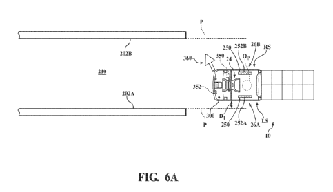
[0031] Figs. 6A-6E are schematic illustrations of a materials
handling vehicle
progressively being driven into an aisle by an operator according to one or
more
embodiments shown and described herein;
[0032] Figs. 6F and 6G depict a flow chart of an example
method for assisting an
operator to properly position a materials handling vehicle in an aisle
according to one
or more embodiments shown and described herein;
[0033] Fig. 7 is a side view of another materials handling
vehicle according to one
or more embodiments shown and described herein;
[0034] Fig. 8 is a perspective view of a cart according to
one or more
embodiments shown and described herein; and
[0035] Fig. 9 is a schematic illustration of a detection
system according to one or
more embodiments shown and described herein.
BEST MODE FOR CARRYING OUT THE INVENTION
100361 The following text sets forth a broad description of
numerous different
embodiments of the present disclosure. The description is to be construed as
exemplary only and does not describe every possible embodiment since
describing
every possible embodiment would be impractical, if not impossible, and it will
be
understood that any feature, characteristic, component, composition,
ingredient,
product, step or methodology described herein can be deleted, combined with or
substituted for, in whole or part, any other feature, characteristic,
component,
composition, ingredient, product, step or methodology described herein. It
should be
understood that multiple combinations of the embodiments described and shown
are
contemplated and that a particular focus on one embodiment does not preclude
its
inclusion in a combination of other described embodiments. Numerous
alternative
embodiments could also be implemented, using either current technology or
technology developed after the filing date of this patent, which would still
fall within
the scope of the claims. All publications and patents cited herein are
incorporated
herein by reference.
Low Level Order Picking Truck
100371 Referring now to the drawings, and particularly to
Figs. 1 and 2, a
materials handling vehicle 10, which is illustrated as a low level order
picking truck,
includes a load handling assembly 12 that is coupled to and extends from a
power unit
7
CA 03163133 2022- 6- 27
WO 2021/167922
PCT/US2021/018284
14. The vehicle 10 forms part of a system 8, which system 8 will be more fully
described below. The load handling assembly 12 includes a pair of forks 16,
each
fork 16 having a load supporting wheel assembly 18. The load handling assembly
12
may include other load handling features in addition to, or in lieu of the
illustrated
arrangement of the forks 16, such as a lead backrest, scissors-type elevating
forks,
outriggers or separate height adjustable forks, as a few examples. Still
further, the
load handling assembly 12 may include load handling features such as a mast, a
load
platform, a collection cage or other support structure carried by the forks 16
or
otherwise provided for handling a load supported and carried by the vehicle
10.
While the present disclosure is made with reference to the illustrated vehicle
10, it
will be apparent to those of skill in the art that the vehicle 10 may comprise
a variety
of other industrial vehicles, such as a forklift truck, a reach truck, etc.,
and that the
following description with reference to the Figures should not be limited to
an order
picking truck unless otherwise specified. Additionally, the vehicle 10 may be
implemented in other formats, styles and features, including a vehicle 10 that
includes
a load handling assembly in the form of a hook, clamp, trailer, such as a
tugger
vehicle, etc.
[0038] The illustrated power unit 14 comprises a step-through
operator station 20
dividing a first end section of the power unit 14 (opposite the forks 16) from
a second
end section (proximate the forks 16). The operator station 20 includes a
platform 21
upon which an operator may stand to drive the vehicle 10 and/or to provide a
position
from which the operator may operate various included features of the vehicle
10. The
operator manually controls traveling functions of the vehicle 10 using
operator
controls 24 provided in the operator station 20.
[0039] The power unit 14 further comprises at least one
steered wheel 108. The
truck 10 comprises a steer-by-wire system for effecting angular movement of
the
steered wheel 108. The steer-by-wire system 80 comprises a control handle 90
forming part of the operator controls 24, a steer motor 114 and the steered
wheel 108,
see Figs. 1 and 3. The term "control handle" is intended to encompass the
control
handle 90 illustrated in Figs. 1 and 2 and like control handles including
steering tillers
and steering wheels. The control handle 90 may be capable of being rotated by
an
operator approximately +/- 60 degrees from a centered position, wherein the
centered
position corresponds to the steered wheel 108 being located in a straight-
ahead
position. A control handle position sensor 100A, shown in Fig. 3, senses the
angular
8
CA 03163133 2022- 6- 27
WO 2021/167922
PCT/US2021/018284
position of the control handle 90 and may comprise a potentiometer. An
operator
may rotate the control handle 90 within the angular range of approximately +/-
60
degrees in the illustrated embodiment to control movement of the steered wheel
108,
which wheel 108 may be capable of rotating approximately +/-90 degrees from a
centered position in the illustrated embodiment. As the control handle 90 is
rotated
by the operator, the control handle position sensor 100A senses that rotation,
i.e.,
magnitude and direction, and generates a steer control signal corresponding to
a
desired angular position of the steered wheel 108 to the controller 103, see
Fig. 3,
which may be communicably coupled to a steer controller 112. The controller
103
generates a corresponding steer actuation signal to the steer controller 112,
which is
coupled to the steer motor 114, to cause the steer motor 114 to move the
steered
wheel 108 to the desired angular position. The control handle 90 and the
control
handle position sensor 100A define a steering device.
100401 Presence sensors 22 (see Fig. 2) may be provided to
detect the presence of
an operator on the vehicle 10. For example, presence sensors 22 may be located
on,
above or under the platform 21, or otherwise provided about the operator
station 20.
In the exemplary vehicle 10 of Fig. 2, the presence sensors 22 are shown in
dashed
lines indicating that they are positioned underneath the platform 21. Under
this
arrangement, the presence sensors 22 may comprise load sensors, switches, etc.
As
an alternative, the presence sensors 22 may be implemented above the platform
21,
such as by using ultrasonic, capacitive or other suitable sensing technology.
The
utilization of presence sensors 22 will be described in greater detail herein.
[0041] The vehicle 10 illustrated in Figs. 1 and 2 includes
first and second exits
26A, 26B, from which the operator can exit the operator station 20. The first
exit 26A
is located at a left side LS of the vehicle 10, and the second exit 26B is
located at a
right side RS of the vehicle 10, as shown in Fig. 2.
[0042] According to one embodiment shown in Fig. 2, the
vehicle 10 may include
a pole that extends vertically from the power unit 14 and includes an antenna
30 that
is provided for receiving control signals from a corresponding wireless remote
control
device 32. The pole may include a light 33 at the top, as shown in Figs. 1 and
2.
According to another embodiment as shown in Fig. 2A, the antenna may be
located
within other vehicle components, such that the control signals from the remote
control
device 32 are received elsewhere on the vehicle 10, as will be discussed
below.
9
CA 03163133 2022- 6- 27
WO 2021/167922
PCT/US2021/018284
[0043]
The remote control device 32 is manually operable by an operator, e.g., by
pressing a button or other control, to cause the remote control device 32 to
wirelessly
transmit at least a first type signal designating a travel request to a
vehicle 10 that is
paired to the remote control device 32. The travel request is a command that
requests
the vehicle 10 to travel, as will be described in greater detail herein.
Although the
remote control device 32 is illustrated in Figs. 1 and 2 as a finger-mounted
structure,
numerous implementations of the remote control device 32 may be implemented,
including for example, a glove structure, a lanyard or sash mounted structure,
etc.
Additional details in connection with the remote control device 32 will be
discussed
in detail below.
[0044]
The vehicle 10 also comprises one or more contactless obstacle sensors 40,
which are provided about the vehicle 10, e.g., towards the first end section
of the
power unit 14 as shown in Figs. 1 and 2. The obstacle sensors 40 are operable
to
define at least one detection zone. For example, at least one detection zone
may
define an area at least partially in front of a forward traveling direction of
the vehicle
when the vehicle 10 is traveling in response to a wirelessly received travel
request
from the remote control device 32, as will also be described in greater detail
herein.
10045]
The obstacle sensors 40 may comprise any suitable proximity detection
technology, such as ultrasonic sensors, image capture devices, infrared
sensors, laser
scanner sensors, etc., which are capable of detecting the presence of
objects/obstacles
or are capable of generating signals that can be analyzed to detect the
presence of
objects/obstacles within the predefined detection zone(s).
In the exemplary
embodiment illustrated in Figs. 1 and 2, the vehicle 10 includes a first
obstacle
detector 42 and a pair of second obstacle detectors 44A and 44B mounted to the
power unit 14. The first obstacle detector 42 is spaced apart from the second
obstacle
detectors 44A and 44B along a vertical axis VA of the vehicle 10 defining a
vertical
direction, i.e., the second obstacle detectors 44A and 44B are located below
(closer to
the ground than) the first obstacle detector 42, see Fig. 1. The second
obstacle
detectors 44A and 44B are spaced apart from each other along a horizontal axis
HA of
the vehicle 10 defining a horizontal direction, see Fig. 2.
[0046]
The first obstacle detector 42 may comprise a sweeping or scanning laser
sensor capable of detecting objects, for example, in first, second, and third
zones Zi,
Z2, Z3 (also referred to herein as scan zones or detection zones), which
first, second,
and third zones Zi, Z2, Z3 may comprise planar zones, see Figs. 1 and 2. The
second
CA 03163133 2022- 6- 27
WO 2021/167922
PCT/US2021/018284
zone Z2 may comprise a "stop zone", wherein the vehicle 10 stops if it is
traveling
under control by the remote control device 32 and an object is detected in the
stop
zone, and the first and third zones Zi and Z3 may comprise left and right
"steer
bumper zones", wherein the vehicle 10 may be steered so as to attempt to avoid
contact with an object if it is traveling under control by the remote control
device 32
and an object is detected in the steer bumper zone. It is noted that the first
obstacle
detector 42 may be capable of detecting objects in additional or fewer zones
than the
three zones Zi, Z2, Z3 illustrated.
[0047] The second obstacle detectors 44A and 44B may comprise
point laser
sensors that are capable of detecting objects between one or more of the zones
Zi, Z2,
Z3 of the first obstacle detector 42 and the vehicle 10, i.e., underneath one
or more of
the zones Zi, Z2, Z3, as illustrated in Fig. 1, and/or past the zones Zi, Z2,
Z3, and are
preferably capable of at least detecting objects underneath the second zone
Z2. The
second obstacle detectors 44A and 44B are thus capable of detecting objects
located
in a non-detect zone DZ of the first obstacle detector 42, see Fig. 1, i.e.,
which non-
detect zone DZ is defined as an area below the zones Zi, 72, 73 and thus not
sensed by
the first obstacle detector 42. Hence, the first obstacle detector 42
functions to detect
objects located along a path of travel of the power unit 14 beyond the non-
detect zone
DZ. while the second obstacle detectors 44A and 44B function to sense objects
along
the path of travel of the power unit 14 in the non-detect zone DZ, which is
located just
in front of the vehicle 10, as shown in Fig. 1.
[0048] Additional sensor configurations and/or detection
zones may be used.
Control Systems
[0049] Referring to Fig. 3, a block diagram illustrates a
control arrangement for
integrating remote control commands with the vehicle 10. A receiver 102, which
may
be a Bluetooth Low Energy (BLE) radio, for example, is provided for receiving
commands issued by the remote control device 32. The receiver 102 passes the
received control signals to the controller 103, which implements the
appropriate
response to the received commands and may thus also be referred to herein as a
master controller. In this regard, the controller 103 is implemented in
hardware and
may also execute software (including firmware, resident software, micro-code,
etc.).
Furthermore, embodiments may take the form of a computer program product
embodied in one or more computer readable medium(s) having computer readable
11
CA 03163133 2022- 6- 27
WO 2021/167922
PCT/US2021/018284
program code embodied thereon. For example, the vehicle 10 may include memory
that stores the computer program product, which, when implemented by a
processor
of the controller 103, implements steer correction as described more fully
herein.
[0050] Thus, the controller 103 may define, at least in part,
a data processing
system suitable for storing and/or executing program code and may include at
least
one processor coupled directly or indirectly to memory elements, e.g., through
a
system bus or other suitable connection. The memory elements can include local
memory employed during actual execution of the program code, memory that is
integrated into a microcontroller or application specific integrated circuit
(ASIC), a
programmable gate array or other reconfigurable processing device, etc.
[0051] The response implemented by the controller 103 in
response to wirelessly
received commands, e.g., via a wireless transmitter 178 of the remote control
device
32 (to be discussed below) and sent to the receiver 102 on the vehicle 10, may
comprise one or more actions, or inaction, depending upon the logic that is
being
implemented. Positive actions may comprise controlling, adjusting or otherwise
affecting one or more components of the vehicle 10. The controller 103 may
also
receive information from other inputs 104, e.g., from sources such as the
presence
sensors 22, the obstacle sensors 40, switches, load sensors, encoders and
other
devices/features available to the vehicle 10 to determine appropriate action
in
response to the received commands from the remote control device 32. The
sensors
22, 40, etc. may be coupled to the controller 103 via the inputs 104 or via a
suitable
truck network, such as a control area network (CAN) bus 110.
[0052] In an exemplary arrangement, the remote control device
32 is operative to
wirelessly transmit a control signal that represents a first type signal such
as a travel
command to the receiver 102 on the vehicle 10. The travel command is also
referred
to herein as a "travel signal", "travel request" or "go signal". The travel
request is
used to initiate a request to the vehicle 10 to travel, e.g., for as long as
the travel signal
is received by the receiver 102 and/or sent by the remote control device 32,
by a
predetermined amount, e.g., to cause the vehicle 10 to advance or jog in a
first
direction by a limited travel distance, or for a limited time. The first
direction may be
defined, for example, by movement of the vehicle 10 in a power unit 14 first,
i.e.,
forks 16 to the back, direction. However, other directions of travel may
alternatively
be defined. Moreover, the vehicle 10 may be controlled to travel in a
generally
straight direction or along a previously determined heading. Correspondingly,
the
12
CA 03163133 2022- 6- 27
WO 2021/167922
PCT/US2021/018284
limited travel distance may be specified by an approximate travel distance,
travel time
or other measure.
[0053] Thus, a first type signal received by the receiver 102
is communicated to
the controller 103. If the controller 103 determines that the travel signal is
a valid
travel signal and that the current vehicle conditions are appropriate, the
controller 103
sends a signal to the appropriate control configuration of the vehicle 10 to
advance
and then stop the vehicle 10. Stopping the vehicle 10 may be implemented, for
example, by either allowing the vehicle 10 to coast to a stop or by initiating
a brake
operation to cause the vehicle 10 to brake to a stop.
[0054] As an example, the controller 103 may be communicably
coupled to a
traction control system, illustrated as a traction motor controller 106 of the
vehicle 10.
The traction motor controller 106 is coupled to a traction motor 107 that
drives the at
least one steered wheel 108 of the vehicle 10. The controller 103 may
communicate
with the traction motor controller 106 so as to accelerate, decelerate, adjust
and/or
otherwise limit the speed of the vehicle 10 in response to receiving a travel
request
from the remote control device 32. As noted above, the controller 103 may also
be
communicably coupled to the steer controller 112, which is coupled to the
steer motor
114 that steers at least one steered wheel 108 of the vehicle 10. In this
regard, the
vehicle 10 may be controlled by the controller 103 to travel an intended path
or
maintain an intended heading in response to receiving a travel request from
the
remote control device 32.
[0055] As yet another illustrative example, the controller
103 may be
communicably coupled to a brake controller 116 that controls vehicle brakes
117 to
decelerate, stop or otherwise control the speed of the vehicle 10 in response
to
receiving a travel request from the remote control device 32. Still further,
the
controller 103 may be communicably coupled to other vehicle features, such as
main
contactors 118, and/or other outputs 119 associated with the vehicle 10, where
applicable, to implement desired actions in response to implementing remote
travel
functionality.
[0056] According to various embodiments, the controller 103
may communicate
with the receiver 102 and with the traction motor controller 106 to operate
the vehicle
under remote control in response to receiving travel commands from the
associated
remote control device 32. Moreover, the controller 103 may be configured to
perform
various actions if the vehicle 10 is traveling under remote control in
response to a
13
CA 03163133 2022- 6- 27
WO 2021/167922
PCT/US2021/018284
travel request and an obstacle is detected in one or more of the detection
zone(s) Z1,
Z2, Z3. In this regard, when a travel signal is received by the controller 103
from the
remote control device 32, any number of factors may be considered by the
controller
103 to determine whether the received travel signal should be acted upon to
initiate
and/or sustain movement of the vehicle 10.
[0057] Correspondingly, if the vehicle 10 is moving in
response to a command
received by the remote control device 32, the controller 103 may dynamically
alter,
control, adjust or otherwise affect the remote control operation, e.g., by
stopping the
vehicle 10, changing the steer angle of the vehicle 10, or taking other
actions. Thus,
the particular vehicle features, the state/condition of one or more vehicle
features,
vehicle environment, etc., may influence the manner in which the controller
103
responds to travel requests from the remote control device 32.
100581 The controller 103 may refuse to acknowledge a
received travel request
depending upon predetermined condition(s), e.g., that relate to environmental
or
operational factor(s). For example, the controller 103 may disregard an
otherwise
valid travel request based upon information obtained from one or more of the
sensors
22, 40. As an illustration, according to various embodiments, the controller
103 may
optionally consider factors such as whether an operator is on the vehicle 10
when
determining whether to respond to a travel command from the remote control
device
32. As noted above, the vehicle 10 may comprise at least one presence sensor
22 for
detecting whether an operator is positioned on the vehicle 10. In this regard,
the
controller 103 may be further configured to respond to a travel request to
operate the
vehicle 10 under remote control when the presence sensor(s) 22 designate that
no
operator is on the vehicle 10. Thus, in this implementation, the vehicle 10
cannot be
operated in response to wireless commands from the remote control device 32
unless
the operator is physically off of the vehicle 10. Similarly, if the obstacle
sensors 40
detect that an object, including the operator, is adjacent and/or proximate to
the
vehicle 10, the controller 103 may refuse to acknowledge a travel request from
the
remote control device 32. Thus, in an exemplary implementation, an operator
must be
located within a limited range of the vehicle 10, e.g., close enough to the
vehicle 10 to
be in wireless communication range (which may be limited to set a maximum
distance of the operator from the vehicle 10). Other arrangements may
alternatively
be implemented.
14
CA 03163133 2022- 6- 27
WO 2021/167922
PCT/US2021/018284
[0059] Any other number of reasonable conditions, factors,
parameters or other
considerations may also/alternatively be implemented by the controller 103 to
interpret and take action in response to received signals from the transmitter
178.
[0060] Upon acknowledgement of a travel request, the
controller 103 interacts
with the traction motor controller 106, e.g., directly or indirectly, e.g.,
via a bus such
as the CAN bus 110 if utilized, to advance the vehicle 10. Depending upon the
particular implementation, the controller 103 may interact with the traction
motor
controller 106 and optionally, the steer controller 112, to advance the
vehicle 10 for as
long as a travel control signal is received. Alternatively, the controller 103
may
interact with the traction motor controller 106 and optionally, the steer
controller 112,
to advance the vehicle 10 for a period of time or for a predetermined distance
in
response to the detection and maintained actuation of a travel control on the
remote
control device 32. Still further, the controller 103 may be configured to
"time out"
and stop the travel of the vehicle 10 based upon a predetermined event, such
as
exceeding a predetermined time period or travel distance regardless of the
detection of
maintained actuation of a corresponding control on the remote control device
32.
[0061] The remote control device 32 may also be operative to
transmit a second
type signal, such as a "stop signal-, designating that the vehicle 10 should
brake
and/or otherwise come to rest. The second type signal may also be implied,
e.g., after
implementing a "travel" command, e.g., after the vehicle 10 has traveled a
predetermined distance, traveled for a predetermined time, etc., under remote
control
in response to the travel command. If the controller 103 determines that a
wirelessly
received signal is a stop signal, the controller 103 sends a signal to the
traction motor
controller 106, the brake controller 116 and/or other truck component to bring
the
vehicle 10 to a rest. As an alternative to a stop signal, the second type
signal may
comprise a "coast signal- or a "controlled deceleration signal" designating
that the
vehicle 10 should coast, eventually slowing to rest.
100621 The time that it takes to bring the vehicle 10 to a
complete rest may vary,
depending for example, upon the intended application, the environmental
conditions,
the capabilities of the particular vehicle 10, the load on the vehicle 10 and
other
similar factors. For example, after completing an appropriate jog movement, it
may
be desirable to allow the vehicle 10 to -coast" some distance before coming to
rest so
that the vehicle 10 stops slowly. This may be achieved by utilizing
regenerative
braking to slow the vehicle 10 to a stop. Alternatively, a braking operation
may be
CA 03163133 2022- 6- 27
WO 2021/167922
PCT/US2021/018284
applied after a predetermined delay time to allow a predetermined range of
additional
travel to the vehicle 10 after the initiation of the stop operation. It may
also be
desirable to bring the vehicle 10 to a relatively quicker stop, e.g., if an
object is
detected in the travel path of the vehicle 10 or if an immediate stop is
desired after a
successful jog operation. For example, the controller 103 may apply
predetermined
torque to the braking operation. Under such conditions, the controller 103 may
instruct the brake controller 116 to apply the brakes 117 to stop the vehicle
10.
[0063] A pairing system 34 can utilize, for example, a close
range system to
wirelessly communicate with a compatible close range system on the wireless
remote
control device 32. Using the pairing system 34, a vehicle 10 and wireless
remote
control device 32 can be "paired" such that a vehicle 10 will transmit and
receive
messages from only its paired wireless remote control device 32. The pairing
system
34 includes components that physically implement the communication method
(e.g.,
Bluetooth, NFC, BLE, Wi-Fi, etc.) used to send messages and includes
components
that programmatically exchange information in an agreed upon protocol to
establish
and maintain a pairing. Thus, the pairing system 34 includes a device that can
execute programmable instructions to implement a predetermined algorithm and
protocol to accomplish pairing operations.
[0064] With reference now to Figs. 1, 2, and 4, Fig. 4
schematically illustrates a
slightly different embodiment of the vehicle 10, which may generally include
the
same components of the vehicle 10 of Figs. 1, 2, and 2A. The system 8
according to
an embodiment further comprises a light source device 200 for designating an
area to
the left side LS or right side RS (see Figs. 2 and 4) of the vehicle 10 as a
limited
operation area and/or an area to the left side LS or right side RS of the
vehicle 10 as a
non-limited operation area. As used herein, the phrase "limited operation
area" may
correspond to an area where a distance Di or D2 between the left or right side
LS, RS
of the vehicle 10 and a boundary object 202 adjacent to which the vehicle 10
is
located, such as a wall, a support post, or a storage structure such as a
rack, shelf,
pallet, and the like, is less than a predetermined distance, and the phrase
"non-limited
operation area" may correspond to an area where the distance Di or D2 is
greater than
or equal to the predetermined distance. Distance Di may be referred to as a
first
distance, distance D2 may be referred to as a second distance, an area to the
left side
LS of the vehicle may be referred to as a first area and an area to the right
side RS of
the vehicle may be referred to as a second area. The -predetermined distance"
may be
16
CA 03163133 2022- 6- 27
WO 2021/167922
PCT/US2021/018284
set to a value such that when the distance Di or D2 is less than the
predetermined
distance, the area corresponding to that distance Di or D2 may be an area not
sufficiently large enough to receive an operator or person while also
maintaining a
minimum clearance distance (which clearance distance may be defined by the
vehicle
owner or vehicle manufacturer) between the operator or person and the boundary
object 202, and when the distance Di or D2 is greater than or equal to the
predetermined distance, the area corresponding to that distance Di or D2 may
be an
area of sufficient size to receive an operator or person and maintain a
minimum
clearance distance between the operator or person and the boundary object 202.
The
distances Di and D2 are measured between the vehicle 10 and the object 202,
e.g.,
between the power unit 14 of the vehicle 10 and the object 202, or between the
load
handling assembly 12 and the object 202, in a lateral direction La, which is
perpendicular to a longitudinal axis LA of the vehicle 10, as shown in Fig. 4.
As noted
above, the controller 103 may receive information from the obstacle sensors
40. The
controller 103 may also be coupled to the light source device 200 to control
operation
of the device 200. The distances Di and D2 may be determined by the controller
103,
for example, using sensor information or data obtained from one or more
sensing
devices coupled to the controller 103, such as the obstacle sensor(s) 40
including the
first obstacle detector 42 or other suitable sensors, or by using positional
data of the
vehicle 10 in relation to known positional data of the object 202. As noted
above, the
first obstacle detector 42 may comprise a scanning laser sensor, which
scanning
sensor may sense or measure distances in X and Y directions and, hence, may
measure the distances Di and D2 between the vehicle 10 and the object(s) 202.
[0065] The light source device 200 may comprise a light
controller 1202 and one
or more light sources 204 coupled to the light controller 1202, wherein the
one or
more light sources 204 may be located on the vehicle 10 and may comprise
visible
lasers, light bars, projectors, etc., which light sources 204 may project
visible indicia
on the floor adjacent to the vehicle 10 on the left side LS and/or right side
RS, and
also optionally in front of and/or behind the vehicle 10. See Fig. 4C for
exemplary
locations of the light sources 204. The light controller 1202 may be coupled
to the
controller 103, which controller 103 controls operation of the one or more
light
sources 204 via the light controller 1202. It is contemplated that in addition
to the
light source locations shown in Fig. 4C, in some embodiments, the light
sources 204
could be incorporated into the vehicle 10 structure such that they are flush
with the
17
CA 03163133 2022- 6- 27
WO 2021/167922
PCT/US2021/018284
body lines of the vehicle 10. In some embodiments, the light sources 204 may
be
coupled to the power unit 14, forks 16, skirt, etc. and positioned such that
they will
not be knocked out of alignment should an object contact the light source 204.
When
the distance Di or D2 between the vehicle 10 and the object 202 is less than
the
predetermined distance, the controller 103 activates or controls via the light
controller
1202 the one or more light sources 204 such that the one or more light sources
204
designate the area between the vehicle 10 and the object 202 as a limited
operation
area in a manner that can be observed by an operator or a person in the
vicinity of the
vehicle, e.g., by illuminating at least a portion of the floor adjacent to the
vehicle 10
corresponding to the limited operation area with visible indicia. When the
distance Di
or D2 between the vehicle 10 and the object 202 is greater than or equal to
the
predetermined distance, the controller 103 controls via the light controller
1202 the
one or more light sources 204 such that they do not designate the area between
the
vehicle 10 and the object 202 as a limited operation area, wherein the
controller 103
may activate or control the one or more light sources 204 via the light
controller 1202
such that they optionally designate the area between the vehicle 10 and the
object 202
as a non-limited operation area in a manner that can be observed by the
operator or a
person in the vicinity of the vehicle 10, e.g., by illuminating at least a
portion of the
floor adjacent to the vehicle 10 corresponding to the non-limited operation
area with
visible indicia that is distinguishable from the indicia used to designate a
limited
operation area.
[0066] When both of the distances Di and D2 are concurrently
greater than or
equal to the predetermined distance, the controller 103 may activate the one
or more
light sources 204 such that they concurrently designate first and second areas
on
opposed sides of the vehicle 10 as non-limited operation areas. Also, when
both of
the distances Di and D2 are concurrently less than the predetermined distance,
the
controller 103 may activate the one or more light sources 204 such that they
concurrently designate the first and second areas on opposed sides of the
vehicle 10 as
limited operation areas. Additionally, when one of the distances Di or D2 is
greater
than or equal to the predetermined distance, and the other of the distances Di
or D2 is
concurrently less than the predetermined distance, the controller 103 may
activate the
one or more light sources 204 via the light controller 1202 such that the one
or more
light sources 204 concurrently designate one of the first and second areas as
a limited
18
CA 03163133 2022- 6- 27
WO 2021/167922
PCT/US2021/018284
operation area and the other of the first and second areas as a non-limited
operation
area.
[0067] According to an embodiment, the one or more light
sources 204 may
designate a limited operation area using a first indicia 206 (see Fig. 4),
such as a first
light pattern, which may have a first light color, and a non-limited operation
area
using a second indicia 208 (see Fig. 4) distinguishable from the first indicia
206, such
as a second light pattern, which may have a second light color different from
the first
light color. As another optional feature, the one or more light sources 204
may
designate that the vehicle 10 is approaching a limited operation area using a
third
indicia 209 that is distinguishable from the first indicia 206 and the second
indicia
208, such as a third light pattern, which may have a third light color. The
controller
103 may cause the third indicia 209 to be illuminated by the one or more light
sources
204 when the distance between the vehicle 10 and the object 202 is greater
than or
equal to the predetermined distance, i.e., a first predetermined distance DA,
but less
than a second predetermined distance DB, see Fig. 4D. Hence, the second and
third
indicia may be illuminated concurrently when the distance between the vehicle
10 and
the object 202 is greater than the first predetermined distance but less than
the second
predetermined distance. Separate light sources 205, coupled to the light
controller
1202, may be provided for generating the third indicia 209.
[0068] The one or more light sources 204 and separate light
sources 205 may be
located anywhere on the vehicle 10, such as on the power unit 14, for example,
and
are preferably located where they can illuminate at least a portion of the
floor between
the load handling assembly 12 and the object 202 and between the power
unit/operator station 14/20 and the object 202.
[0069] In embodiments, the controller 103 will only actuate
the one or more light
sources 204 and separate light sources 205 to illuminate the applicable
indicia if the
vehicle 10 is determined to be in an aisle 210. In such an embodiment, the
light
sources 204 and separate light sources 205 will not be activated while the
vehicle 10
is in a location other than in an aisle 210. The vehicle 10 may be determined
to be in
an aisle 210, for example, by the controller 103 using sensor data from the
obstacle
sensor(s) 40, by a warehouse management system (WMS) that communicates with
the
vehicle 10, and/or using positional data of the vehicle 10, etc.
100701 This embodiment provides an operator or other person
in the vicinity of
the vehicle 10 with a suggestion as to where they might not want to walk
(limited
19
CA 03163133 2022- 6- 27
WO 2021/167922
PCT/US2021/018284
operation area), in addition to a suggestion where they may want to walk (non-
limited
operation area). When the device 200 is located on the vehicle 10, the device
200
moves with the vehicle 10, which is beneficial in that there will be no
limited
operation area when the vehicle 10 is not in the vicinity. In other words, an
area may
only become a limited operation area when a vehicle 10 is present and is
located close
to the object 202, e.g., the wall or rack.
[0071] Referring now to Fig. 4A, an exemplary method 230 is
shown to illustrate
designating an area around the vehicle 10 as a limited operation or non-
limited
operation area. At step 232, the vehicle 10 is located within an aisle 210 and
the
distance Di from the vehicle 10 to a first rack adjacent to the left side LS
of the
vehicle 10 is less than the predetermined distance, i.e., the first
predetermined
distance, and concurrently the distance D2 from the vehicle 10 to a second
rack
adjacent to the right side RS of the vehicle 10 is greater than or equal to
the
predetermined distance i.e., the first predetermined distance. At step 234,
the device
200, actuated by the controller 103, illuminates at least a portion of the
floor between
the left side LS of the vehicle 10 and the first rack with the first indicia
206 to
designate this area as a limited operation area For example, the controller
103 may
control the device 200 such that the device 200 generates a first indicia 206
(see Fig.
4) comprising a first light pattern and a first light color. At optional step
236
(optional steps are indicated by dashed boxes in the figures), the device 200,
actuated
by the controller 103, concurrently illuminates at least a portion of the
floor between
the right side RS of the vehicle 10 and the second rack with the second
indicia 208 to
designate this area as a non-limited operation area. For example, the
controller 103
may control the device 200 such that the device 200 generates a second indicia
208
(see Fig. 4) comprising a second light pattern and a second light color. At
step 238,
once the distance Di from the vehicle 10 to the first rack is greater than or
equal to the
predetermined distance, the device 200, in response to being controlled by the
controller 103, removes the first indicia 206, and may optionally illuminate
at least a
portion of the floor between the left side LS of the vehicle 10 and the first
rack with
the second indicia 208 to designate this area as a non-limited operation area.
As
another optional step 240, as the vehicle 10 approaches a position where the
distance
Di or D. from the vehicle 10 to the first or second rack will soon be less
than the first
predetermined distance DA and is currently only less than the second
predetermined
distance DB, the device 200 illuminates at least a portion of the floor
between the
CA 03163133 2022- 6- 27
WO 2021/167922
PCT/US2021/018284
corresponding left side LS or right side RS of the vehicle 10 and the
respective first or
second rack with the third indicia 209 to indicate that the vehicle 10 is
approaching a
position where the area between the vehicle 10 and the rack will become a
limited
operation area.
[0072] Referring again to Fig. 4, the system 8 may further
comprise a sensing
system 250 that detects when an operator has exited the operator station 20 of
the
vehicle 10. The sensing system 250 is also able to distinguish whether an
operator
exited the vehicle from the first exit 26A or the second exit 26B. The sensing
system
250 may comprise, for example, first and second photoelectric sensors, such as
light
curtain sensors 252A, 252B, one located at the first exit 26A and the other
located at
the second exit 26B. The light curtain sensors 252A, 252B are capable of
detecting
an operator passing through the respective exits 26A, 26B so as to distinguish
through
which exit 26A, 26B the operator exited the vehicle 10. The sensing system 250
may
further comprise the operator presence sensors 22 (see Fig. 2), wherein the
data from
the operator presence sensors 22 may additionally be used to determine that an
operator has exited the vehicle 10, and used in combination with the data from
the
light curtain sensors 252A, 252B to determine through which exit 26A, 26B the
operator exited the vehicle 10.
[0073] According to embodiments, if the vehicle 10 is
positioned within a
predefined distance from an object 202, e.g., a wall or rack, that is located
adjacent to
the side of the vehicle 10 from which an operator exited the vehicle 10, as
determined
by the sensing system 250, at least one function of the vehicle 10 may be
modified by
the controller 103, e.g., disabled, limited, or activated. The predefined
distance is
measured in the lateral direction LE) between the vehicle 10 and the object
202. The
predefined distance may be the same as, similar to, or different than the
predetermined distance discussed above. This embodiment could be used along
with
the light source(s) 204, such that when stepping out of the vehicle, the
operator will
know whether they are stepping into a limited operation zone or a non-limited
operation zone, i.e., based on the first or second indicia 206 or 208
illuminated on the
floor adjacent to the vehicle 10. Hence, the light source(s) 204 could
designate an
area to the left side LS or right side RS of the vehicle 10 as a limited
operation area
when the vehicle is positioned within a predefined distance from an object
202,
wherein the predefined distance may be the same as the predetermined distance
discussed above.
21
CA 03163133 2022- 6- 27
WO 2021/167922
PCT/US2021/018284
[0074] The function(s) of the vehicle that are modified by
the controller 103 may
be, for example, traction control/traveling movement of the vehicle, e.g., the
maximum allowable speed of the vehicle 10 may be limited or the traction
control of
the vehicle 10 may be disabled, functions of the load handling assembly, e.g.,
lift
and/or lower may be limited or disabled, remote control functionality of the
vehicle
via the remote control device 32 may be disabled, a vehicle alert system may
be
activated, e.g., to initiate an alarm, etc.
[0075] As noted above, the data from the operator presence
sensors 22 may
additionally be used to determine that an operator has exited the vehicle 10.
In this
regard, the system 250 is additionally capable of detecting a situation
wherein, for
example, the operator has moved one foot out of the vehicle 10, but the other
foot is
still inside the vehicle 10, i.e., one of the light curtain sensors 252A or
252B detected
a pass through (e.g., the operator's foot/leg passing through), but the
operator
presence sensors 22 still detect the presence of the operator on the platform
21. In
this situation, the aforementioned function(s) of the vehicle may or may not
be
disabled by the controller 103, and/or the vehicle 10 may issue an alarm or
other
warning for the operator to move their foot/leg back into the operator station
20.
Alternative measures may also be taken, such as, for example stopping the
vehicle 10
until the operator returns their foot/leg into the operator station 20.
[0076] With reference now to Fig. 4B, an exemplary method 270
is provided to
illustrate detecting that an operator has exited the vehicle 10. At step 272,
the system
250 detects that an operator has exited the vehicle 10. At step 274, which may
be
performed concurrently with step 272, the system 250 detects from which exit
26A,
26B the operator exited. Assuming in this example that the operator exited the
vehicle 10 to a side of the vehicle 10 where a boundary object is located
within the
predefined distance from the vehicle 10, at least one function of the vehicle
10 is
modified by the controller 103, e.g., limited, disabled, or activated, at step
276. The
at least one function of the vehicle 10 may be returned to its previous state
by the
controller 103 when the operator performs one or more actions, such as, for
example,
moving back onto the vehicle 10, moving out of the area between the boundary
object
and the vehicle 10, actuating a manual input, such as a button/switch, etc.
located on
the vehicle 10 or on a touchscreen TS (See Fig. 4C), or by shutting down and
then
restarting the vehicle 10.
22
CA 03163133 2022- 6- 27
WO 2021/167922
PCT/US2021/018284
[0077] This embodiment could also be used with a vehicle that
includes only a
single exit. That is, if a single-exit vehicle is positioned within the
predefined
distance from a boundary object (e.g., a wall or rack) that is located
adjacent to the
side of the vehicle having the exit, at least one function of the vehicle 10
may be
disabled as described herein.
[0078] This embodiment could also be used with a vehicle that
includes two exits,
but where only one of the exits would include a light curtain sensor. This
configuration could be used, for example, where, while driving in an aisle,
the vehicle
will always be located closer to one side of the aisle than the other, e.g., a
situation
where the vehicle always drives along the left or right side of the aisle. In
this case,
only the exit corresponding to the side of the aisle that the vehicle drives
along may
include a light curtain sensor.
100791 Turning now to Fig. 5, according to an embodiment, the
system 8 further
includes at least one sensing device 300, which may be the obstacle sensor(s)
40
discussed herein and/or other sensing device(s). The sensing device 300
monitors
areas in front of and next to the vehicle 10 on the left and right sides LS,
RS thereof
Specifically, the sensing device 300 monitors a first area Al adjacent to the
left side
LS of the vehicle 10, a second area A2 in front of the vehicle 10, and a third
area A3
adjacent to the right side RS of the vehicle 10. The areas Al, A2, and A3 in
Fig. 5 are
shown in exemplary locations. Data from the sensing device 300 is used by the
controller 103 to identify position information of the vehicle 10 relative to
one or
more boundary objects 202 near which the vehicle 10 is located. Referring to
the
embodiment shown in Fig. 5, the position of the vehicle 10 relative to a first
rack
202A adjacent to the left side LS of the vehicle 10 is determined by the
controller
103, and the position of the vehicle 10 relative to a second rack 202B
adjacent to the
right side RS of the vehicle 10 is determined by the controller 103. The
position
information may comprise the lateral distance from the vehicle 10 to the first
rack
202A and/or to the second rack 202B.
[0080] The position information may be used by the controller
103 to determine if
the vehicle 10 is located in an aisle 210. For example, the vehicle 10 may be
determined to be located in an aisle 210 if the distance Di between the
vehicle 10 and
the first rack 202A, plus the distance D2 between the vehicle 10 and the
second rack
202B, plus the width of the vehicle 10 are equal to or within a predefined
range to a
known width of the aisle 210 (if the distances Di and D2 were to be measured
from
23
CA 03163133 2022- 6- 27
WO 2021/167922
PCT/US2021/018284
the longitudinal axis LA of the vehicle 10 to the respective racks 202A, 202B,
as
opposed to being measured from the left and right sides LS, RS of the vehicle
10, the
width of the vehicle 10 would be taken out of this equation).
[0081] The position information may also be used by the
controller 103 to
determine if the vehicle 10 is located in a desired position within an aisle
210. For
example, if the distances from the vehicle 10 to the first and second racks
202A, 202B
are equal or within a predetermined tolerance, the vehicle 10 may be
determined to be
located in the center of the aisle 210. Or, if the distance from the vehicle
10 to one of
the first rack 202A or the second rack 202B is equal to or within a
predetermined
tolerance to a predefined hugging distance (to be discussed below), and,
optionally, if
the operator is determined by the controller 103 not to be present on the
vehicle 10
(e.g., via information from the sensing system 250), it may be determined that
the
vehicle 10 is in hugging mode (to be described below), or is in the proper
position to
begin hugging mode.
100821 The position information of the vehicle 10 relative to
the boundary
object(s) can be used by the controller 103 to modify at least one vehicle
parameter.
Exemplary vehicle parameters that can be modified in this way include: a
maximum
allowable travel speed (e.g., based on the position information, the maximum
allowable travel speed can be reduced from a normal maximum allowable travel
speed to a reduced maximum allowable travel speed or increased from the
reduced
maximum allowable travel speed to the normal maximum allowable travel speed);
a
maximum allowable turning angle (e.g., based on the position information, the
maximum allowable turning angle can be reduced from a normal maximum allowable
turning angle to a reduced maximum allowable turning angle or increased from
reduced maximum allowable turning angle to the normal maximum allowable
turning
angle); a steered-wheel-to-steering-device ratio; one or more vehicle lights
(e.g.,
based on the position information, one or more lights on the vehicle 10 can be
switched on or off); a lifting function of the load handling assembly (e.g.,
based on
the position information, lifting/lowering function(s) of the load handling
assembly 12
can be adjusted, such as lift/lower speed or a maximum lift height, and/or the
load
handling assembly 12 may be automatically raised or lowered to a desired
height);
indicia used to indicate that the vehicle is located in a particular area
(e.g., based on
the position information, the first, second, or third indicia 206, 208, 209
may be
switched on or off); and/or, based on the position information, an alert may
be given
24
CA 03163133 2022- 6- 27
WO 2021/167922
PCT/US2021/018284
to indicate the presence of the vehicle 10 in an aisle 210, such as an audible
alert,
visual alert, alert on a display screen (e.g., the touchscreen TS), etc.
[0083] As noted above, the controller 103 receives the steer
control signal from
the control handle position sensor 100A, which senses the angular position of
the
control handle 90 within the angular range of approximately +/- 60 degrees in
the
illustrated embodiment. Since a current steer control signal corresponds to a
current
position of the control handle 90 falling within the range of from about +/-
60 degrees
and the steered wheel 108 is capable of rotating through an angular range of
+/- 90
degrees, the controller 103 converts the current control handle position, as
indicated
by the steer control signal, to a corresponding desired angular position of
the steered
wheel 108 by multiplying the current control handle position by a steered-
wheel-to-
steering-device ratio, such as 90/60 or 1.5/1.0, e.g., an angular position of
the control
handle 90 of +60 degrees equals a desired angular position of the steered
wheel 108 of
+90 degrees. For example, if the angular position of the control handle 90 is
+60
degrees, the controller 103 multiplies +60 degrees by the ratio of 1.5/1.0 to
determine
a desired angular position of the steered wheel 108 equal to +90 degrees and
generates
a corresponding steer actuation signal to the steer controller 112.
[0084] The steered-wheel-to-steering-device ratio may equal
60/60 or 1.0/1Ø For
example, if the angular position of the control handle 90 is +60 degrees, the
controller
103 may multiply +60 degrees by the ratio of 1.0/1.0 to determine a desired
angular
position of the steered wheel 108 equal to +60 degrees.
[0085] The controller 103 may modify at least one of a
maximum allowable
turning angle of the steered wheel 108 or the steered-wheel-to-steering-device
ratio
when the position information indicates that the vehicle 10 is positioned
within a
predefined distance from an object 202, such as a wall or a rack that is
located
adjacent to the side of the vehicle 10. The controller 103 may modify at least
one of
the maximum allowable turning angle of the steered wheel 108 or the steered-
wheel-
to-steering-device ratio independent of whether the vehicle is being manually
or
remotely controlled by an operator. It is also contemplated that the
controller 103
may only modify at least one of the maximum allowable turning angle of the
steered
wheel 108 or the steered-wheel-to-steering-device ratio when an operator is
determined to be not present in the operator station 20, e.g., as determined
by the
sensing system 250, or when an operator is remotely controlling the vehicle 10
with a
remote control device 32 that is paired to the vehicle 10.
CA 03163133 2022- 6- 27
WO 2021/167922
PCT/US2021/018284
[0086] The predefined distance, as noted above, is measured
in the lateral
direction LD between the vehicle 10 and the object 202. The predefined
distance may
be the same as, similar to, or different than the predetermined distance
(defined such
that when the distance Di or D2 is less than the predetermined distance, the
area
corresponding to that distance Di or D2 may be an area not sufficiently large
enough
to receive an operator or person while also maintaining a minimum clearance
distance
between the operator or person and the boundary object 202) discussed above.
For
example, the controller 103 may reduce the maximum allowable turning angle for
the
steered wheel 108 from a first maximum allowable turning angle to a second
maximum allowable turning angle when the position information indicates that
the
vehicle 10 is positioned within the predefined distance from the wall or rack,
wherein
the second maximum allowable turning angle is less than the first maximum
allowable turning angle. In Fig. 4E, the vehicle 10 is illustrated as being
within a
predefined distance DPD of an object 202 such that the maximum allowable
turning
angle of the steered wheel 108 is reduced to a smaller value, thereby reducing
the
likelihood that the forks 16 on the vehicle 10 or a load carried by the forks
16 may
swing into the wall or rack during a sharp turn. It is also contemplated that
when the
vehicle 10 is within the predefined distance DPD of an object 202, the steered-
wheel-
to-steering-device ratio may be changed from a larger ratio (1.5/1.0) to a
smaller ratio
(1.0/1.0) to make the steering of the steered wheel 108 less sensitive.
[0087] In a further example, the controller 103 may modify at
least one of a
maximum allowable turning angle of the steered wheel 108 or the steered-wheel-
to-
steering-device ratio when the position information, sensed by the sensing
device 300,
indicates that the vehicle 10 is positioned within a predefined distance from
an object
202, such as a wall or a rack that is located adjacent to the side of the
vehicle 10, and
object information, also sensed by the sensing device 300, indicates that a
further
object is in front of or to the side of the vehicle 10, i.e., within a sensing
range of the
sensing device 300. For example, the controller 103 may reduce the maximum
allowable turning angle from a first maximum allowable turning angle to a
second
maximum allowable turning angle when the position information indicates that
the
vehicle 10 is positioned within the predefined distance from the wall or rack
and the
object information indicates that a further object is in front of or to the
side of the
vehicle, wherein the second maximum allowable turning angle is less than the
first
maximum allowable turning angle. In Fig. 4E, the vehicle 10 is illustrated as
being
26
CA 03163133 2022- 6- 27
WO 2021/167922
PCT/US2021/018284
within a predefined distance DPD of an object 202 and, further, an object 203,
such as
a box, shown in phantom, is located in front of the vehicle 10 such that the
maximum
allowable turning angle of the steered wheel 108 is reduced to a smaller
value,
thereby reducing the likelihood that the forks 16 or a load carried by the
forks 16 may
swing into the wall or rack during a sharp turn It is also contemplated that
when the
vehicle 10 is within the predefined distance DpD of an object 202 and a
further object
203 is sensed as being in front of or to the side of the vehicle 10, the
steered-wheel-to-
steering-device ratio may be changed from a larger ratio to a smaller ratio to
make the
steering of the steered wheel 108 less sensitive.
[0088] In Fig. 4F, a further materials handling vehicle 200A
is illustrated
comprising an order picking truck with a mast assembly 1230. The mast assembly
1230 forms part of a load handling assembly 218 coupled to and extending from
a
power unit 14. The load handling assembly 218 further comprises a fork
carriage
assembly 224 coupled to the mast assembly 1230 for movement relative to the
mast
assembly 1230 and with the mast assembly 1230. The fork carriage assembly 224
comprises a fork carriage 226 (also referred to herein as a "lift carriage-)
and a pair of
forks 216 coupled to the fork carriage 226. The mast assembly 1230 comprises
one or
more mast sections. The exemplary mast assembly 1230 illustrated in Fig. 4F is
a
two-stage mast assembly comprising first and second mast sections or weldments
1232 and 1234. The fork carriage 226 is attached to and moves relative to the
second
mast section or weldment 1234 and is lifted relative to the second mast
section 1234
via a primary lift ram/cylinder assembly (not illustrated) mounted to the
second
section 1234. The second section or weldment 1234 moves relative to the first,
stationary mast section or vveldment 1232, wherein the first mast section 1232
is
mounted to the power unit 14. One or more hydraulic secondary lift
ram/cylinder
assemblies (not shown) are fixed at their cylinder bases to the power unit 14
or first
mast section 1232 and the rams are fixed to the second mast section 1234. As
the
rams of the secondary assemblies extend, the rams cause the second mast
section
1234, along with the fork carriage assembly 224, to move relative to the first
mast
section 1232.
[0089] In yet another example, the controller 103 may modify
at least one of a
load handling assembly lift height, a maximum allowable turning angle of the
steered
wheel 108 or the steered-wheel-to-steering-device ratio when the position
information
indicates that the vehicle 10 is positioned within an aisle. The lift height
of the lift
27
CA 03163133 2022- 6- 27
WO 2021/167922
PCT/US2021/018284
carriage may define the load handling assembly lift height. For example, the
controller 103 may reduce a maximum lift height to which the fork carriage 226
and
forks 216 may be raised, i.e., a maximum lift height of the lift carriage,
once the
sensing device 300 senses and the controller 103 determines that the vehicle
10 is
located within an aisle. In a further embodiment, the controller 103 may
reduce the
maximum lift height to which the fork carriage 226 and forks 216 may be raised
only
when the sensing device 300 senses and the controller 103 determines that the
vehicle
is located within an aisle having a designated or predefined aisle width (also
referred to herein as -a first aisle width") or a width equal to or less than
the
predefined or first aisle width. It is noted that some freezers have a low
ceiling and
also have very narrow aisles. Hence, when the controller 103 determines that
the
vehicle 200A is moving through a narrow aisle having the designated or first
aisle
width, the controller 103 will limit the height to which the fork carriage 226
and forks
216 can be elevated to a lower maximum lift height to avoid contacting the
ceiling. In
a further example, the controller 103 may reduce the maximum allowable turning
angle for the steered wheel 108 from a first maximum allowable turning angle
to a
second maximum allowable turning angle when the position information indicates
that the vehicle 10 is located within an aisle, wherein the second maximum
allowable
turning angle is less than the first maximum allowable turning angle. It is
still further
contemplated that the controller 103 may modify the maximum allowable turning
angle of the steered wheel 108 to a reduced value concurrently with the
sensing
device 300 first sensing that the vehicle 10 is located within an aisle and
may also
modify, i.e., return, the maximum allowable turning angle of the steered wheel
108 to
its higher value as soon as the sensing device 300 senses that the vehicle 10
is no
longer located within an aisle. It is also contemplated that when the
controller 103
determines that the vehicle 10 is located within an aisle the steered-wheel-to-
steering-
device ratio may be changed from a larger ratio (1.5/1.0) to a smaller ratio
(1.0/1.0) to
make the steering of the steered wheel 108 less sensitive.
[0090] In a still further example, the controller 103 may
modify at least one of a
load handling assembly lift height, a maximum allowable turning angle of the
steered
wheel 108 or the steered-wheel-to-steering-device ratio when the position
information
indicates that the vehicle 10 is positioned within an aisle, and object
information,
sensed by the sensing device 300, indicates that a further object is in front
of or to the
side of the vehicle 10. For example, the controller 103 may reduce a maximum
height
28
CA 03163133 2022- 6- 27
WO 2021/167922
PCT/US2021/018284
to which the fork carriage 226 and forks 216 may be raised, once the sensing
device
300 senses and the controller 103 determines that the vehicle 10 is located
within an
aisle and a further object is in front of or to the side of the vehicle 200A.
Further, the
controller 103 may reduce the maximum allowable turning angle from a first
maximum allowable turning angle to a second maximum allowable turning angle
when the position information indicates that the vehicle 10 is positioned
within an
aisle and the object information indicates that a further object is in front
of or to the
side of the vehicle, wherein the second maximum allowable turning angle is
less than
the first maximum allowable turning angle. It is also contemplated that the
steered-
wheel-to-steering-device ratio may be changed from a larger ratio to a small
ratio
when the vehicle enters an aisle and an object is detected in front of or to
the side of
the vehicle 10 to make the steering of the steered wheel 108 less sensitive.
100911 In another example, when the position information
indicates that the
vehicle 10 is located within an aisle, the controller 103 may modify the load
handling
assembly lift height by moving the lift carriage 226 to an intermediate
height. Thus,
when the controller 103 determines that the vehicle has entered an aisle, the
controller
103 will automatically raise the lift caniage 226 to an intermediate height
such that an
operator, when picking items, does not have to bend over to place the items on
the
forks 216 located in a lower position, i.e., near a surface on which the
vehicle is
traveling. The intermediate height may be dependent on circumstances in which
the
vehicle 10 is being operated. For example, the intermediate height may be
dependent
on the aisle in which the vehicle 10 is currently being operated and/or the
operator
that is currently operating the vehicle 10. When the vehicle 10 is being
operated in an
aisle wherein the items to be placed on the forks 216 are large, it may be
advantageous for the intermediate height to be preconfigured to a lower
position than
when the vehicle 10 is being operated in an aisle wherein the items to be
placed on the
forks 216 are small. Similarly, when the vehicle 10 is being operated by a
short
operator, it may be advantageous for the intermediate height to be
preconfigured to a
lower position than when the vehicle 10 is being operated by a tall operator.
[0092] Moreover, in the case where the position information
is used by the
controller 103 to modify multiple vehicle parameters, select one(s) of the
vehicle
parameters may be modified only situationally. For example, one or more of the
vehicle parameters may be modified by the controller 103 only when an operator
is
determined to be not present in the operator station 20, e.g., as determined
by the
29
CA 03163133 2022- 6- 27
WO 2021/167922
PCT/US2021/018284
sensing system 250. As another example, one or more of the vehicle parameters
may
be modified by the controller 103 only when an operator is remotely
controlling the
vehicle 10 with a remote control device 32 that is paired to the vehicle 10.
[0093] With reference now to Fig. 5A, an exemplary method 330
is shown to
illustrate determining position information of the vehicle 10. At step 332,
the vehicle
is determined to be located within an aisle 210 by the controller 103 using
the
position information from the sensing device 300. According to this step 332,
the
position information is used to determine that the distance Di from the
vehicle 10 to a
first rack 202A on a first side of the vehicle 10, plus the distance D2 from
the vehicle
10 to a second rack 202B positioned on a second side of the vehicle, plus the
width of
the vehicle 10 (assuming the distances Di and D2 are measured from the left
and right
edges of the vehicle 10 to the respective racks 202A, 202B) are equal to or
within a
predefined range to a known width of the aisle 210.
100941 At step 334, the vehicle 10 is determined to be
located in the center of the
aisle 210 by the controller 103 using the position information from the
sensing device
300, when the distance Di from the vehicle 10 to the first rack 202A is equal
to or
within a predetermined tolerance to the distance D2 from the vehicle 10 to the
second
rack 202B. The vehicle 10 is then moved within the aisle 210 at step 336,
e.g., by the
operator using the operator controls 24 or the remote control device 32. In
its new
location in the aisle 210, at step 338 the vehicle 10 is determined by the
controller 103
to be located at or within a predetermined tolerance to a predefined hugging
distance
(the hugging distance is explained in more detail below) from one of the first
or the
second rack 202A or 202B. At step 340 the operator is determined to have
exited the
operator station 20, e.g., by the controller 103 using information from the
sensing
system 250. Based on the vehicle 10 being at or within a predetermined
tolerance to
the predefined hugging distance from one of the first or the second rack 202A
or
202B, and based on the operator having exited the vehicle 10, the vehicle 10
is
determined by the controller 103 to be in or ready to enter hugging mode at
step 342.
It is noted that, while the predefined hugging distance may be set such that
the vehicle
10 is maintained in the center of the aisle 210 while the vehicle 10 is
hugging an
object, this exemplary embodiment assumes that the predefined hugging distance
is
set such that the vehicle 10 will be located closer to one of the first or the
second rack
202A or 202B than the other.
CA 03163133 2022- 6- 27
WO 2021/167922
PCT/US2021/018284
[0095] In accordance with another embodiment, the system 8
may further include
a positioning assistance system 350, as shown in Figs. 5, and 6A-6E. The
positioning
assistance system 350, which may be incorporated into the controller 103,
provides
assistance to an operator that is driving the vehicle 10, such as by using the
operator
controls 24 to position the vehicle 10 within an aisle 210. The positioning
assistance
system 350 receives information from the sensing device 300 to determine the
distances Di and D2 from the vehicle 10 to one or more boundary objects, e.g.,
first
and second racks 202A and 202B located on the respective left and right sides
LS, RS
of the vehicle 10, and also to determine the heading of the vehicle 10
relative to the
boundary object(s), wherein the heading is defined as the angle that the truck
is
oriented within the aisle 210 with respect to at least one of the boundary
object(s).
100961 The assistance provided by the positioning assistance
system 350 may
comprise at least one of audible, tactile, or visual cue(s) to indicate at
least one of a
spacing from the vehicle 10 to at least one boundary object, e.g., a distance,
such as a
lateral distance, from the vehicle 10 to a boundary object, and/or a heading
of the
vehicle 10 with respect to the boundary object. In this regard, the
positioning
assistance system 350 comprises a cue device 352 for implementing the audible,
tactile, and/or visual cues. For example, the audible, tactile, and/or visual
cues may
be actuated to indicate that: the vehicle is located at a distance that is
equal to or
greater than a desired distance from the boundary object the vehicle is
located at a
proper heading with respect to the boundary object; the vehicle is not located
at a
distance that is equal to or greater than the desired distance from the
boundary object
and/or the vehicle is not located at the proper heading with respect to the
boundary
object. Cues for indicating different information may be distinguishable from
one
another so as to relay to the operator the meaning of the cue.
[0097] Figs. 6A-6E depict a vehicle 10 progressively entering
an aisle 210 while
being manually driven by an operator OP, who is shown in an exemplary position
on
the vehicle 10 in Figs. 6A-6E. Figs. 6A-6E show exemplary positions of the
vehicle
during one particular iteration of the operator Op driving the vehicle 10 into
the
aisle 210. It is understood that, in practice, an operator may take any number
of
different paths into an aisle, with appropriate responses by the positioning
assistance
system 350 based on the position of the vehicle 10.
100981 In Fig. 6A, the distance Di from the vehicle 10 to a
first rack 202A (as
noted above, the distances Di and D2 are measured between the vehicle 10 and
the
31
CA 03163133 2022- 6- 27
WO 2021/167922
PCT/US2021/018284
racks 202A, 202B in the lateral direction LD) is less than the desired
distance, i.e.,
distance Di from the vehicle 10 to the first rack 202A is not equal to or
greater than
the desired distance. In this situation, the positioning assistance system 350
may issue
an audible, tactile, and/or visual first cue 360 in a first manner for the
operator OP to
steer the vehicle 10 away from the first rack 202A. If the first cue 360 is a
visual cue,
it may be displayed by the cue device 352 on the floor in front of the vehicle
10 and to
the right side RS thereof. As an example, the first cue 360 is shown in Fig.
6A as an
arrow pointing away from the first rack 202A, indicating that the vehicle 10
must be
steered to the right, but any suitable cue 360 could be used. As another
example, the
first cue 360 may be shown on a display device (e.g., as a message or as an
arrow
pointing to the right on the touchscreen TS shown in Fig. 4C) located on the
vehicle
10. It is noted that the terms first, second, third, etc. as used herein with
respect to the
various cues described are not meant to be limited to be used for the stated
purpose,
i.e., the various cues described herein for Figs. 6A-6E follow a specific
exemplary
progression of the vehicle 10 being driven by the operator Op into the aisle
210.
Thus, the action associated with the "first cue" described herein could be
associated
with a second, third, etc. cue in another progression of a vehicle 10 being
driven by an
operator Op into an aisle 210.
[0099] Moving on to Fig. 6B, the operator Op has steered the
vehicle 10 away
from the first rack 202A and toward the second rack 202B. In Fig. 6B, the
vehicle 10
is no longer in a position where the distance Di from the vehicle 10 to the
first rack
202A is less than the desired distance, such that the first cue 360 has been
turned off
(another cue distinguishable from the first cue 360 may be actuated by the
positioning
assistance system 350, at least briefly or intermittently, to indicate that
the distance Di
from the vehicle 10 to the first rack 202A is greater than or equal to the
desired
distance). However, in Fig. 6B, the vehicle 10 is not located at a proper
heading with
respect to the second rack 202B. A proper heading of the vehicle 10 may be
defined
as a heading of the vehicle 10 with respect to a boundary object, such as one
or both
of the racks 202A, 202B that is within a predefined range, for example,
wherein the
longitudinal axis LA of the vehicle 10 is from 0 to 10 degrees relative to a
plane P
defined by the edge of the respective rack 202A or 202B. In this situation,
the
positioning assistance system 350 may issue an audible, tactile, and/or visual
second
cue 362 in a second manner for the operator OP to steer the vehicle 10 away
from the
second rack 202B in order to reduce the angle of the vehicle 10 relative to
the second
32
CA 03163133 2022- 6- 27
WO 2021/167922
PCT/US2021/018284
rack 202B. If the second cue 362 is a visual cue, it may be displayed by the
cue
device 352 on the floor in front of the vehicle 10 and to the left side LS
thereof. As
an example, the second cue 362 is shown in Fig. 6B as an arrow pointing away
from
the second rack 202B, indicating that the vehicle 10 must be steered to the
left, but
any suitable cue 362 could be used. As another example, the second cue 362 may
be
shown on the display device (e.g., as a message or as an arrow pointing to the
left on
the touchscreen TS). It is noted that in a typical aisle 210, the first and
second racks
202A, 202B are generally parallel, such that the vehicle 10 may be determined
to be
at a proper or improper heading with respect to either of the racks 202A,
202B.
[00100] Turning now to Fig. 6C, the operator Op has steered the vehicle 10
away
from the second rack 202B and toward the first rack 202A, thus changing the
heading
of the vehicle 10. In Fig. 6C, the vehicle 10 is no longer in a position where
the
heading with respect to the second rack 202B is improper, such that the second
cue
362 has been turned off (another cue distinguishable from the second cue 362
may be
actuated by the positioning assistance system 350, at least briefly or
intermittently, to
indicate that the vehicle 10 is no longer in a position where the heading with
respect
to the second rack 202B is improper). However, in Fig. 6C, the distance D2
from the
vehicle 10 to the second rack 202B is less than the desired distance. In this
situation,
the positioning assistance system 350 may issue an audible, tactile, and/or
visual third
cue 364 in a third manner for the operator OP to steer the vehicle 10 away
from the
second rack 202B. If the third cue 364 is a visual cue, it may be displayed by
the cue
device 352 on the floor in front of the vehicle 10 and to the left side LS
thereof. As
an example, the third cue 364 is shown in Fig. 6C as an arrow pointing away
from the
second rack 202B, indicating that the vehicle 10 must be steered to the left,
but any
suitable cue 364 could be used. As another example, the third cue 364 may be
shown
on the display device (e.g., as a message or as an arrow pointing to the left
on the
touchscreen TS).
[00101] With reference now to Fig. 6D, the operator Op has steered the vehicle
10
away from the second rack 202B and toward the first rack 202A, In Fig. 6D, the
vehicle 10 is no longer in a position where the distance D2 from the vehicle
10 to the
second rack 202B is less than the desired distance, such that the third cue
364 has
been turned off (another cue distinguishable from the third cue 364 may be
actuated
by the positioning assistance system 350, at least briefly or intermittently,
to indicate
that the distance Di from the vehicle 10 to the second rack 202B is greater
than or
33
CA 03163133 2022- 6- 27
WO 2021/167922
PCT/US2021/018284
equal to the desired distance). However, in Fig. 6D, the vehicle 10 is not
located at a
proper heading with respect to the first rack 202A. In this situation, the
positioning
assistance system 350 may issue an audible, tactile, and/or visual fourth cue
366 in a
fourth manner for the operator OP to steer the vehicle 10 away from the first
rack
202A in order to reduce the angle of the vehicle 10 relative to the first rack
202A. If
the fourth cue 366 is a visual cue, it may be displayed by the cue device 352
on the
floor in front of the vehicle 10 and to the right side RS thereof. As an
example, the
fourth cue 366 is shown in Fig. 6D as an arrow pointing away from the first
rack
202A, indicating that the vehicle 10 must be steered to the right, but any
suitable cue
366 could be used. As another example, the fourth cue 366 may be shown on the
display device (e.g., as a message or as an arrow pointing to the right on the
touchscreen TS).
1001021 Referring finally to Fig. 6E, the vehicle 10 is
positioned generally in the
center of the aisle 210, is located at a distance that is equal to or greater
than the
desired distance from both the first and second racks 202A, 202B, and has a
straight
heading with respect to the first and second racks 202A, 202B, i.e., the
longitudinal
axis LA of the vehicle 10 in Fig 6E is generally parallel to the planes P
defined by the
edges of the first and second racks 202A, 202B. In this situation, the
positioning
assistance system 350 may, at least briefly or intermittently, issue an
audible, tactile,
and/or visual fifth cue 368 in a fifth manner for the operator Or that the
vehicle 10 is
located at a distance equal to or greater than the desired distance from the
first and
second racks 202A, 202B, and that the vehicle 10 is oriented at the proper
heading.
As an example, the fifth cue 368 is shown in Fig. 6E as an arrow on the floor
pointing
straight down the aisle 210, but any suitable cue 368 could be used. As
another
example, the fifth cue 368 may be shown on the display device (e.g., as a
message or
as an indica, such as a checkmark, on the touchscreen TS). As another feature,
separate cues may be used to indicate that the vehicle 10 is located at a
position equal
to or greater than the desired distance from the racks 202A, 202B, and that
the vehicle
is oriented at the proper heading. It is noted that the positioning assistance
system
350 may issue separate audible, tactile, and/or visual cues for the operator
Or that the
vehicle 10 is located at a distance equal to or greater than the desired
distance from
the first and second racks 202A, 202B, and that the vehicle 10 is oriented at
the proper
heading.
34
CA 03163133 2022- 6- 27
WO 2021/167922
PCT/US2021/018284
[00103] One or more of the cues 360, 362, 364, 366, 368 may be distinguishable
from one or more of the others. For example, if the cues 360, 362, 364, 366,
368 are
visual cues, they may be different colors or shapes, have different
illumination
patterns (blinking, changing intensity, size), etc.
[00104] Only once the vehicle 10 is located at a position where the distances
Di
and D2 are equal to or greater than the desired distance from both racks 202A,
202B,
and the vehicle 10 is oriented at the proper heading, the vehicle 10 is able
to be
remotely controlled by an operator using the remote control device 32, i.e.,
the vehicle
is not able to be remotely controlled by an operator using the remote control
device
32 unless the vehicle 10 is located at a position where the distances Di and
132 are
equal to or greater than the desired distance from both racks 202A, 202B, and
the
vehicle 10 is oriented at the proper heading. As noted above, the positioning
assistance system 350 may issue an audible, tactile, and/or visual fifth cue
368 to
indicate this positioning of the vehicle 10. While being remotely controlled,
the
vehicle may be capable of being operated in hugging mode, where the vehicle 10
moves down the aisle 210 and hugs one of the first or second racks 202A or
202B,
wherein while hugging the rack 202A or 202B, the vehicle 10 maintains the
predefined hugging distance from the rack 202A or 202B being hugged.
[00105] With reference to Fig. 6F and 6G, an exemplary method 370 is shown to
illustrate assisting an operator to properly position the vehicle 10 in the
aisle 210. It is
noted that the sequence of the steps listed below and shown in Figs. 6F and 6G
could
be in a different order, and/or these steps could repeat themselves based on
the
position of the vehicle 10 as it is entering the aisle 210 and/or as the
vehicle 10 is
driven within the aisle 210.
[00106] At step 372, the operator Op is driving the vehicle 10
into the aisle 210,
e.g., using the operator controls 24 on the vehicle 10. At step 374, it is
determined
that the vehicle 10 is located inside of the desired distance from the first
rack 202A,
and a first cue 360 is issued by the positioning assistance system 350. At
step 376,
the operator Op responds to the first cue 360 by steering the vehicle 10 away
from the
first rack 202A, and once the vehicle 10 is located outside of the desired
distance from
the first rack 202A, the first cue 360 is turned off.
[00107] At step 378, it is determined that the vehicle 10 is
not located at a proper
heading with respect to the second rack 202B, and a second cue 362 is issued
by the
positioning assistance system 350. At step 380, the operator OP responds to
the
CA 03163133 2022- 6- 27
WO 2021/167922
PCT/US2021/018284
second cue 362 by steering the vehicle 10 relative to the boundary object,
e.g., away
from the second rack 202B in the embodiment shown, and once the vehicle 10 is
within the range that defines the proper heading of the vehicle 10 with
respect to the
second rack 202B, the second cue 362 is turned off.
[00108] At step 382, it is determined that the vehicle 10 is
located inside of the
desired distance from the second rack 202B, and a third cue 364 is issued by
the
positioning assistance system 350. At step 384, the operator Op responds to
the third
cue 364 by steering the vehicle 10 away from the second rack 202B, and once
the
vehicle 10 is located outside of the desired distance from the second rack
202B, the
third cue 364 is turned off
[00109] After turning away from the second rack 202B, at step 386, it is
determined that the vehicle 10 is not located at a proper heading with respect
to the
first rack 202A, and a fourth cue 366 is issued by the positioning assistance
system
350. At step 388, the operator OP responds to the fourth cue 366 by steering
the
vehicle 10 away from the first rack 202A, and once the vehicle 10 is within
the range
that defines the proper heading of the vehicle 10 with respect to the first
rack 202A,
the fourth cue 366 is turned off.
[00110] At step 390, it is determined that the vehicle 10 is
located at a position
equal to or greater than the desired distance from both racks 202A, 202B, and
the
vehicle 10 is oriented at the proper heading with respect to the first and
second racks
202A, 202B. With both of these criteria being met, a fifth cue 368 is issued
by the
positioning assistance system 350, indicating that the vehicle 10 is in a
position where
it is able to be operated remotely by the operator OP using the remote control
device
32.
[00111] With reference now to Fig. 7, a materials handling vehicle 10
according to
an embodiment may be equipped with a load handling assembly 12 that has
shorter
forks 16 than a traditional materials handling vehicle of the same type. Forks
16'
having a traditional fork length LT are shown in Fig. 7 in dashed/phantom
lines, and
forks 16 having lengths LSF according to an embodiment are shown in Fig. 8 in
solid
lines. Exemplary traditional forks 16' for the type of vehicle 10 shown in
Fig. 7 have
a length L' of about 2400mm to about 2880mm, and exemplary forks 16 according
to
an embodiment have a length LSF of about 1000mm to about 2150mm.
[00112] A cart 500 for use with a materials handling vehicle according to
another
embodiment is shown in Fig. 8. The cart 500 may comprise a removable or
36
CA 03163133 2022- 6- 27
WO 2021/167922
PCT/US2021/018284
permanent part of the loading handling assembly 12 and includes one or more
shelves
or levels 502A, 502B, 502C (the cart 500 includes three levels in the
embodiment
shown, but any number of levels can be used), where each level 502A-502C
supports
items picked by the operator. Each level 502A-502C may include sidewalls 504
at
left and right sides of the cart 500 and a backwall 506 at the back of the
cart, which
sidewalls 504 and backwall 506 prevent picked items from falling out of the
cart 500
and also from extending outwardly from the sides or back of the cart 500. A
width
Wc of the cart 500 may be equal to or less than the width of the vehicle 10.
[00113] The cart 500 further includes rollers 508, which enable picked items
to be
rolled toward the backwall 506 of the cart 500 as the items are picked by the
operator
and placed on the cart 500.
1001141 Each of the features of the cart 500, i.e., the sidewalls 504 and
backwall
506, the width Wc, and the rollers 508, in addition to the shorter forks 16
described in
Fig. 7, allow a materials handling vehicle 10 to drive and turn in a narrow
aisle 210,
while militating against contact of the forks 16, the cart 500, and/or the
picked items
with walls or racks in the aisle 210. Specifically, due to the shorter forks
16, during a
turning maneuver, the forks 16 do not swing out to the opposite side of the
turn as far
as traditional forks. The sidewalls 504 and backwalls 506 of the cart 500 help
to
prevent picked items on the cart 500 from extending outwardly from the sides
and
back of the cart 500, so as to avoid contact with the walls or racks in the
aisle 210.
The width Wc of the cart 500 being no greater than the width of the vehicle 10
prevents the sides of the cart 500 from extending outwardly past the sides of
the
vehicle 10, so as to avoid contact of the cart 500 with the walls or racks.
The rollers
508 permit an operator to load the cart 500 with picked items from the back of
the cart
500, such that the operator can walk behind the vehicle 10 while remotely
controlling
the vehicle 10 with the remote control device 32, as opposed to walking
alongside the
vehicle 10 where space might be limited in a narrow aisle 210.
[00115] With reference now to Fig. 9, a detection system 600 is provided for
monitoring a designated area, such as an aisle 210 of a warehouse or other
facility.
The detection system 600 may be configured to prevent or discourage a second
materials handling vehicle 10B from entering the designated area where a first
materials handling vehicle 10A is already present. In this regard, the
detection
system 600 may be configured to provide a warning, e.g., warning sound or
flashing
light, to alert the operator of the second vehicle 10B not to enter the area.
37
CA 03163133 2022- 6- 27
WO 2021/167922
PCT/US2021/018284
Alternatively, the detection system 600 may be configured such that the second
vehicle 10B is prevented from moving into the designated area, for example,
such as
with travel override commands sent to the second vehicle 10B from the
detection
system 600 or from the warehouse manage system WMS (the detection system 600
would be in communication with the warehouse manage system WMS).
[00116] The detection system 600 could be mounted in the vicinity of the
designated area, such as at the top of a rack, or on a wall or ceiling of the
facility.
Alternatively, the detection system 600 could be incorporated into the
vehicles 10A,
10B themselves. For example, the vehicles 10A and 10B could know the location
of
each other, either by direct communication between the vehicles 10A, 10B, or
through
communication with the warehouse manage system WMS.
[00117] This embodiment may be particularly beneficial in a facility where
space
is limited, such as a facility having narrow aisles (e.g., where two vehicles
would not
fit side by side in the aisle), and also where vehicles are being controlled
remotely,
e.g., via wireless remote control devices 32 such as those disclosed herein.
[00118] The various features, aspects, and embodiments described herein can be
used in any combination(s) with one another, or on their own.
[00119] Having thus described embodiments in detail, it will be apparent that
modifications and variations are possible without departing from the scope of
the
appended claims.
38
CA 03163133 2022- 6- 27