Note: Descriptions are shown in the official language in which they were submitted.
ACOUSTIC DETECTION OF DEFECTS IN A PIPELINE
Technical Field
The present invention relates to an acoustic sensor system for detecting
defects in a
pipeline wall.
Further, the present invention relates to an inline inspection device
comprising the
acoustic sensor system.
Further, the present invention relates to a method for detecting defects in a
pipeline
wall.
Further, the present invention relates to a computer program comprising
instructions
which, when the computer program is executed by a computer, cause the computer
to
execute steps of the method.
Further, the present invention relates to a data carrier signal that transmits
the com-
puter program.
Further, the present invention relates to a computer-readable medium
comprising in-
structions which, when executed by a computer, cause the computer to execute
steps
of the method.
Background of the Invention
Known sensors for detecting defects, such as cracks, in pipeline walls are
restricted in
their detection characteristics to specific defect sizes. When increasing the
sensitivity,
complex configurations and correction methods are necessary in order to
achieve suf-
ficient accuracy in the detection of the defects.
-1-
7627099
CA 03163397 2022- 6- 29
Description of the invention
Based on this situation, it is an object of the present invention to provide
an improved
sensor system for defect detection of a pipeline wall, an improved inline
inspection
device, an improved method for defect detection of a pipeline wall, an
improved com-
puter program, an improved data carrier signal, and an improved computer-
readable
medium.
In particular, it is intended to simplify a configuration while increasing the
sensitivity so
that, for example, defects with smaller dimensions are detected.
The object of the invention is achieved by the features of the independent
claims. Ad-
vantageous embodiments are provided in the dependent claims. Where technically
possible, the teachings of the dependent claims may be combined arbitrarily
with the
teachings of the independent claims and the dependent claims.
According to the invention, thus, an acoustic sensor system for detecting a
defect in a
pipeline wall is provided. The sensor system comprises at least one
transmitter unit
configured to emit ultrasound in the direction of the pipeline wall and to
detect an ul-
trasound echo reflected from the pipeline wall, and a control unit signally
connected to
the at least one transmitter unit and configured to detect the defects of the
pipeline wall
based on an occurring change in the ultrasound echo.
According to the invention, moreover, an inline inspection device (ILI) for
inspecting a
pipeline wall is provided, comprising at least one acoustic sensor system
according to
the invention or according to any one of the advantageous embodiments
described
below.
According to the invention, furthermore, a method for detecting a defect of a
pipeline
wall is provided. The method comprises the following steps: operating at least
one
transmitter unit to emit ultrasound toward the pipeline wall and to detect an
ultrasound
-2-
7627099
CA 03163397 2022- 6- 29
echo reflected from the pipeline wall; and operating a control unit signally
connected
to the at least one transmitter unit for detecting the defect of the pipeline
wall based on
an occurring change in the ultrasound echo. The method preferably comprises
steps
corresponding to features of the sensor system according to any one of the
advanta-
geous embodiments described below.
It is preferred that the sequence of the aforementioned method steps may be
varied,
unless technically required in the aforementioned sequence.
According to the invention, further a computer program comprising instructions
is pro-
vided which, when the computer program is executed by a computer, cause the
com-
puter to carry out a previously described method. A computer program is a
collection
of instructions for executing a particular task, designed to solve a
particular class of
problems. The instructions of a program are designed to be executed by a
computer,
wherein it is required that a computer is able to execute programs in order to
function.
According to the invention, further a data carrier signal is provided that
transmits the
computer program described above.
According to the invention, furthermore, a computer-readable medium comprising
in-
structions is provided which, when executed by a computer, cause the computer
to
carry out a previously described method.
The basic idea of the invention and individual aspects of the claimed subject
matter of
the invention are explained below, and preferred modified embodiments of the
inven-
tion are further described below. Explanations, in particular concerning
advantages
and definitions of features, are basically descriptive and preferred, but not
limiting ex-
amples. Where an explanation is limiting, this is expressly mentioned.
Thus, the basic idea of the present invention is to use ultrasonic sensors to
detect
defects. In particular, defects in the form of corrosion, dents and cracks can
be
-3-
7627099
CA 03163397 2022- 6- 29
detected. The cracks can be of any shape. For example, cracks extending at an
angle
to the ultrasonic sensors can be detected. In addition, the size and shape of
cracks of
various shapes, such as: circular cracks, angled cracks, or slanted cracks can
be de-
tected. In this case, it is not necessary to specifically configure the system
with respect
to the different crack shapes. Furthermore, the geometry of the pipeline can
be deter-
mined. Angled beam probes are not required.
When detecting defects, it is taken into account that a large part of the
ultrasonic echo
signal can be detected by the transmitter unit due to reflection from an
intact inner wall
of the pipeline. In case of corrosion of the inner wall, a change of the
signal corre-
sponding to a change of the ultrasonic echo is detectable at the transmitter
unit. Sur-
prisingly, it has been found that a single transmitter unit is sufficient for
the sensor
system to reliably detect corrosion. No complex setup is necessary. In other
words, a
single transmitter unit can initially emit ultrasound via a beam exit surface.
The trans-
mitter unit can detect the ultrasonic echo via its beam exit surface, which
then corre-
sponds to its beam entrance surface. In the case of installation of the sensor
system
in an inline inspection device (ILI), the single transmitter unit per circle
sector of a cross-
sectional area of the pipeline is therefore sufficient to detect corrosion.
Depending on
the number of circle sectors into which the cross-sectional area is divided, a
corre-
sponding number of sensor systems is selected. However, only one transmitter
unit is
required per circle sector, from which defects are detected separately from
other sen-
sor units.
For the detection of corrosion, therefore, very little configuration effort is
required, since
it is not necessary to drive several transmitter units or to tap and evaluate
signals from
them. There is also little drive electronics that would have to be used in a
sensor sys-
tem or in an ILI. This allows particularly compact setups of sensor systems
and also
ILls, in particular if they are to be used for the inspection of pipelines
affected by cor-
rosion. Multiple transmitter units can be used, for example, to increase the
redundancy
and thus the reliability of measurement results.
-4-
7627099
CA 03163397 2022- 6- 29
According to a modified embodiment of the invention, it is provided that a
single trans-
mitter unit forms an immersion normal beam probe; or multiple transmitter
units form
an immersion normal beam probe (immersion probe). In other words, the acoustic
sen-
sor system comprises immersion probes. In immersion testing, unlike manual
testing
in which a probe is brought into direct manual contact with a component,
ultrasound is
introduced into a component under test through a medium, such as water or oil,
over
a longer delay line. A normal beam probe is also referred to as an ultrasonic
normal
probe, a single transducer vertical probe, or a longitudinal wave probe. A
normal beam
probe comprises a piezoelectric transducer that generates mechanical voltage
waves,
and thus longitudinal waves, as a result of electrical excitation by voltage
pulses.
Preferably, the acoustic sensor system is formed by one or more immersion
probes.
The transmitter unit(s) is/are configured to emit a normal beam. In
particular, the trans-
mitter unit(s) is/are adapted to exclusively emit a normal beam. In other
words, each
of the transmitter units is a normal beam probe. The transmitter units are to
be aligned
perpendicular to an inner surface of the pipeline during material inspection.
In particular, the acoustic sensor system comprising the immersion probes is
part of
an ILI that moves inside a pipeline in order to detect cracks and corrosion at
an inner
or outer surface of the pipeline. In particular, the immersion normal beam
probes are
used for automated inspection for detects.
According to a modified embodiment of the invention, it is provided that the
control unit
is configured to drive at least a first transmitter unit of the sensor system,
for emitting
ultrasound towards the pipeline wall and for detecting an ultrasound echo
reflected
from the pipeline wall; temporarily drive at least one second transmitter unit
of the sen-
sor system for detecting the ultrasound echo reflected from the pipeline wall;
and de-
tect the defect of the pipeline wall based on an occurring change of the
ultrasound
echo.
-5-
7627099
CA 03163397 2022- 6- 29
In this context, the term "first transmitter unit" or "second transmitter
unit" refers to the
type of driving. The second transmitter unit is only driven temporarily.
In other words, advantageously two transmitter units are already sufficient
for reliably
detecting cracks. The use of the second transmitter unit only temporarily for
detecting
ultrasonic echoes and not for emitting ultrasound has the advantage that the
second
transmitter unit is not applied with a voltage in order to emit an ultrasonic
signal. This
has the advantage of significantly improving the signal-to-noise ratio, which
allows for
an improved sensitivity of defect detection, while also significantly reducing
a configu-
ration effort due to filtering of detected signals. More than two transmitter
units could
be used to improve the detection reliability.
Advantageously, ultrasonic echo signals are evaluated, which are generated or
de-
tected by only driving the first transmitter unit, or by driving the first
transmitter unit and
the second transmitter unit. Here, it is taken into account that a large part
of the ultra-
sonic echo signal can be detected by the first transmitter unit by reflection
from an
intact inner wall of the pipeline. In case of corrosion of the inner wall, a
change of the
signal corresponding to a change of the ultrasonic echo is detectable at the
first trans-
mitter unit. In this case, the second transmitter unit does not need to be
driven in order
to detect ultrasonic echoes. Even if the first and the second transmitter
units are each
driven by the control unit, a change in signal can be detected at the first
transmitter
unit and at the second transmitter unit. A crack can be detected in this case.
In the
case that there is a crack in the pipeline, a signal change is detected. In
the case of
particularly small cracks, these can advantageously already be detected by the
second
transmitter unit. When a crack occurs, part of the ultrasound is blocked by
the crack.
Part of the ultrasound is reflected by the crack. In case of localization of
the crack
between ultrasound exit and entrance surfaces of the emitting transmitter unit
and the
detecting transmitter unit, a strength of the detected signal of the
ultrasound echo de-
creases. In case of approach of emitting and reflecting transmitter unit to
the crack, a
strength of the signal increases compared to a signal emitted through an
intact inner
wall of the pipeline, which is then detected. Transmitter units operating in
the
-6-
7627099
CA 03163397 2022- 6- 29
aforementioned ultrasonic frequency range are particularly suitable for
corrosion and
crack detection in a pipeline. Here, there is no restriction in the detection
of the depth
of the cracks and also the measurement of deep cracks. Furthermore,
detachments of
coatings of the pipeline walls can be detected at the pipelines. Preferably,
the trans-
mitter units are aligned with respect to the inner pipeline wall in such a way
that the
ultrasound impinges on the surface of the inner pipeline wall approximately
corre-
sponding to a normal beam.
According to a modified embodiment of the invention, it is provided that at
least one
transmitter unit is configured for emitting and detecting low-frequency
ultrasound,
wherein an amount of a wavelength of the low-frequency ultrasound is greater
than/equal to an amount of a wall thickness of the pipeline wall. In
particular, the
amount of the wavelength of the low-frequency ultrasound is related to the
amount of
the wall thickness WT of the pipeline wall according to 2=WT/n, where n is a
natural
number. The transmitter unit(s) operating at low frequency is/are thus used
for low
frequency ultrasonic testing, or LF UT. It is conceivable that both the
transmitter unit(s)
permanently driven for emission and detection and the transmitter unit(s)
temporarily
driven for detection are designed to emit and/or detect low frequency
ultrasound. Low
frequency ultrasound covers a frequency range of 100 kHz to 1.5 MHz. An
operation
in a low-frequency range of 500 KHz or 600 KHz is preferred. In particular,
the trans-
mitter unit(s) is/are designed as a broadband sensor. The pipelines can carry
gas as
well as water or oil. Cracks with a depth of 2 mm and larger can be detected
and
measured. The depth of a crack is a distance along a measured wall thickness
between
the inner wall of the pipeline and an outer wall of the pipeline. Contaminated
pipelines
or pipelines with wax on the inner walls can be examined. Even pipelines with
thick
internal coatings can be inspected for defects.
According to a modified embodiment of the invention it is provided that at
least one
transmitter unit is designed to emit and detect high frequency ultrasound. The
trans-
mitter unit(s) operating at high frequency is/are thus used for high frequency
ultrasonic
testing (HFUT). It is conceivable that both the transmitter unit(s)
permanently driven
-7-
7627099
CA 03163397 2022- 6- 29
for emission and detection and the transmitter unit(s) temporarily driven for
detection
are designed to emit and/or detect high frequency ultrasound. High-frequency
ultra-
sound covers a frequency range in the order of magnitude of megahertz starting
from
a frequency of more than 1.5 MHz. The pipelines may carry gas, water or oil.
Cracks
with a depth of 0.5 mm and larger can be detected and measured. Furthermore,
very
small corrosion spots can be detected, for example pitting corrosion. In
particular,
when using transmitter units with high-frequency ultrasound, a mathematical
model is
used to determine absolute sizes of defects.
According to a modified embodiment of the invention, it is provided that the
sensor
system comprises at least one transmitter unit designed to emit and detect low-
fre-
quency ultrasound and at least one transmitter unit designed to emit and
detect high-
frequency ultrasound. This makes the sensor system universally applicable for
the
aforementioned fields of application, by use of both frequency spectra.
According to a modified embodiment of the invention, it is provided that, in
particular
when only the first transmitter unit is driven or the first and the second
transmitter unit
are driven, the control unit is configured to evaluate the change of the
ultrasonic echo
corresponding to a change of an ultrasonic echo divergence generated by
corrosion in
order to detect corrosion. The ultrasonic echo divergence is taken into
account assum-
ing that both emitted ultrasound and an echo approximately propagate radially.
The
ultrasonic echo divergence corresponds to a beam cross section of an
ultrasonic echo
beam scattered at the pipeline wall with respect to a certain distance, i.e. a
kind of
opening angle of the ultrasonic beam of the ultrasonic echo. The corrosion
detection
hereby becomes particularly reliable due to a redundant determinability of
corrosion-
related defects.
According to a modified embodiment of the invention, it is provided that, in
particular
when only driving the first transmitter unit in a pitch catch mode or driving
the first and
the second transmitter unit respectively in a pitch catch mode, the control
unit is
-8-
7627099
CA 03163397 2022- 6- 29
configured to evaluate the change of the ultrasonic echo corresponding to a
change of
an ultrasonic echo divergence generated by corrosion in order to detect
corrosion.
According to a modified embodiment of the invention, it is provided that, in
particular
when only driving the first transmitter unit in a pulse echo mode or driving
the first and
the second transmitter unit respectively in a pulse echo mode, the control
unit is con-
figured to evaluate the change of the ultrasonic echo corresponding to a
change of an
ultrasonic echo divergence generated by corrosion in order to detect
corrosion.
In other words, according to the two previously described modified embodiments
of the
pitch catch mode (PC mode) or the pulse echo mode (PE mode), corrosion
detection
is carried out from analysis of the received ultrasonic waves from the PE mode
or the
PC mode. In the so-called pulse echo mode (PE mode), the transmitter unit(s)
emits
(emit) ultrasound and detects (detect) an ultrasonic echo. In the PE mode, the
same
transmitter units that emit the ultrasound can also detect it. In particular,
the driving of
the at least one first and the at least one second transmitter unit comprises,
in particular
corresponds to, a combination of the PE mode and/or the so-called pitch catch
mode
or PC mode, in which one/a plurality of transmitter unit(s) emits/emit
ultrasound and
one/a plurality of other transmitter unit(s) detects/detect an ultrasonic
echo.
According to a modified embodiment of the invention, it is provided that, in
particular
in case of temporarily driving the second transmitter unit, the control unit
is configured
to determine a wall thickness of the pipeline wall based on a difference
between an
inner wall echo time and an outer wall echo time. An inner wall echo is an
echo which
is reflected from a pipeline side facing the transmitter in the direction of
the transmitter.
An outer wall echo is an echo which is reflected in the direction of the
transmitter from
a pipeline side facing away from the transmitter and forming the outer shell
of the pipe-
line. The advantageous embodiment has the advantage that a wall thickness of
the
pipeline can be determined from the detected ultrasonic echo without much
filtering of
a signal. Advantageously, such a determination method is used when a
transmitter unit
operating at high-frequency is used.
-9-
7627099
CA 03163397 2022- 6- 29
According to a modified embodiment of the invention it is provided that, in
particular in
case of temporarily driving the second transmitter unit, the control unit is
configured to
determine a wall thickness of the pipeline wall based on at least two
resonance fre-
quencies of the outer wall echo or based on at least one resonance frequency
of the
outer wall echo and a duration of the at least one resonance frequency of the
outer
wall echo. The resonance frequency is the frequency at which an amplitude of
the
pipeline wall capable of oscillation is greater than as in the case of
excitation by adja-
cent frequencies (amplitude resonance). In particular, in addition to the
resonance fre-
quencies, their corresponding harmonics are additionally used. With advantage
such
a determination method by use of the resonance frequencies is used when using
a
transmitter unit operating at low frequencies.
According to a modified embodiment of the invention, it is provided that, in
particular
in case of temporarily driving the second transmitter unit, the control unit
is configured
to determine a wall thickness of the pipeline wall based on at least one outer
wall echo
time and at least one period duration of an outer wall echo at this at least
one outer
wall echo time. The period duration is the Fourier transform of a frequency of
the outer
wall echo. This method is advantageously applicable for the evaluation of
signals of
transmitter units operated at high-frequency or at low-frequency. The
additional use of
the outer wall echo times is in particular conceived in order to improve a
signal-to-noise
ratio. According to a particularly advantageous embodiment of the invention,
it is pro-
vided that the control unit is configured to determine a wall thickness of the
pipeline
wall based on an outer wall echo time and at least one period duration of an
outer wall
echo at this outer wall echo time point of an ultrasonic signal transformed by
means of
a second degree Fast Fourier transform (F FT).
According to a modified embodiment of the invention, it is provided that, in
particular
in case of temporarily driving the second transmitter unit, the control unit
is configured
to perform crack detection and crack size determination based on
amplitudes/integrals
of components of an unprocessed ultrasound signal, a first degree Fourier
transformed
- 10 -
7627099
CA 03163397 2022- 6- 29
ultrasound signal, or a second degree Fourier transformed ultrasound signal.
In partic-
ular, the signal component is an outer wall echo and/or (a) resonance
frequency.
According to a modified embodiment of the invention, it is preferably provided
that, in
particular in case of temporarily driving the second transmitter unit, the
control unit is
configured to perform a crack detection and a crack size determination based
on at
least one amplitude of at least one resonance frequency and/or at least one
amplitude
of an outer wall echo. According to a modified embodiment of the invention, it
is pref-
erably provided that, in particular in case of temporarily driving the second
transmitter
unit, the control unit is configured to perform a crack detection and a crack
size deter-
mination based on amplitudes of resonance frequencies and/or an amplitude of
an
outer wall echo. According to a particularly advantageous embodiment of the
invention,
it is provided that, in particular in the case of temporarily driving the
second transmitter
unit, the control unit is configured to perform crack detection and crack size
determi-
nation based on amplitudes of resonance frequencies and/or amplitudes of an
outer
wall echo. According to a particularly advantageous embodiment of the
invention, it is
provided that the control unit is configured to perform crack detection and
crack size
determination based on amplitudes of resonance frequencies in a frequency
domain
and/or an amplitude(s) of an outer wall echo of an ultrasonic signal
transformed by
second degree FFT. Advantageously, such a determination method is used when us-
ing one/a plurality of transmitter unit(s) operating at low-frequency or one/a
plurality of
transmitter unit(s) operating at high-frequency.
According to a modified embodiment, the control unit is configured to perform
crack
detection and crack size determination for signals of low-frequency ultrasound
based
on at least one amplitude of at least one resonance frequency. According to a
modified
embodiment, the control unit is configured to perform crack detection and
crack size
determination for signals of high-frequency ultrasound based on at least one
amplitude
of at least one outer wall echo, in particular based on a
periodicity/repetition rate of at
least one outer wall echo. In the case of a detection of cracks based on a
high-fre-
quency signal, this signal is in particular Fourier transformed.
- 11 -
7627099
CA 03163397 2022- 6- 29
According to a modified embodiment of the invention, it is provided that the
control unit
is configured to detect cracks in an order of magnitude of 2 mm in a high-
frequency
ultrasonic signal during an evaluation of raw data of a signal (raw signal) in
which an
amplitude is plotted against time. Here, in particular, a linear evaluation of
the raw
signal is performed for high-frequency signals and a non-linear evaluation is
performed
for low-frequency signals.
According to a modified embodiment of the invention, it is provided that the
control unit
is configured to detect cracks in an order of magnitude of 2 mm for a high-
frequency
ultrasonic signal when evaluating a first degree Fourier transform of a
signal. Further,
the control unit is configured to detect a crack depth based on a magnitude of
ampli-
tude/integral of signal components. Further, the control unit is configured to
detect a
crack based on a mode in a frequency range in the order of three times a shear
wave
or 1.6 times a longitudinal mode.
According to a modified embodiment of the invention, it is provided that the
control unit
is configured to detect cracks in the order of 2 mm for a high frequency
ultrasonic signal
when evaluating a second degree Fourier transform of a signal. Further, the
control
unit is configured to detect a crack depth based on a magnitude of
amplitude/integral
of signal components. Further, the control unit is configured to determine a
crack size
at a signal portion of high frequency ultrasound based on at least one of an
amplitude
and an integral of at least one outer wall echo.
According to a modified embodiment of the invention, it is provided that an
attenuation
of the ultrasonic echo is proportional to a depth of the defect. Due to the
linear rela-
tionship a crack depth can be particularly easily be determined based on the
amplitude.
According to a modified embodiment of the invention, it is provided that the
transmitter
unit is configured to emit ultrasound or to detect ultrasound in a phase-
dependent man-
ner. Such a configuration of the transmitter unit is particularly advantageous
for sensor
- 12 -
7627099
CA 03163397 2022- 6- 29
systems which have to be designed compactly. For example, the first
transmitter unit
can be designed as a phase-dependent ultrasound emitting and detecting
physical
unit.
According to a modified embodiment of the invention, a single transmitter unit
config-
ured to detect reflected ultrasound and a plurality of transmitter units
arranged around
the single transmitter unit, each configured to emit ultrasound, are provided
in the sen-
sor system. The arrangement of the transmitter units with respect to each
other is de-
fined with respect to an ultrasound entrance surface or an ultrasound exit
surface. The
arrangement of the transmitter units is such that the ultrasound exit or
entrance sur-
faces of all transmitter units lie in a common plane. Surprisingly, it has
been found that
a particularly good sensitivity for smaller cracks can be achieved when using
a single,
in particular centrally arranged, transmitter unit for detecting the
ultrasonic echoes. If
the single transmitter unit is arranged centrally, the sensitivity is
particularly good. The
surrounding transmitter units, which emit ultrasound, thus emit a particularly
large
amount of energy, which can propagate through the gas in a pipeline and
penetrate
the pipeline wall, so that, moreover, particularly good measurement signals
can be
achieved. Furthermore, the effects of misalignments of the sensor system can
be com-
pensated with advantage.
According to a particularly advantageous embodiment of the invention, it is
provided
that the second transmitter unit is formed by a one-piece ring at its
ultrasonic exit sur-
face and an ultrasonic entrance surface of the first transmitter unit is
arranged inside
the ring, preferably concentrically. A one-piece configuration of the ring
means in par-
ticular a closed one-piece ultrasonic exit surface of the second transmitter
unit. Here,
it has been found that the effects described for the previous embodiment occur
even
more pronounced in this particularly advantageous embodiment. According to a
further
particularly preferred embodiment, the second transmitter unit is arranged
concentri-
cally to the first transmitter unit in such a way that the first and the
second transmitter
unit have a common circle center. In particular, the first transmitter unit is
circular in
shape. In the above-described embodiments, it is possible in particular to
obtain a good
- 13 -
7627099
CA 03163397 2022- 6- 29
signal-to-noise ratio at a deviation of the alignment of a low-frequency
ultrasonic beam
to the pipeline wall of 2 degrees from a surface normal of a pipeline wall at
a wall
thickness of more than 30 mm. For thinner wall thicknesses, even greater
deviations
in alignment are possible, while still maintaining a sufficient signal-to-
noise ratio. With
high-frequency ultrasound, a good signal-to-noise ratio can be achieved with a
devia-
tion of one degree from the surface normal. The latter is especially true for
wall thick-
nesses of 30 mm and more. For smaller wall thicknesses, a good signal-to-noise
ratio
can also be achieved with high-frequency ultrasound with a deviation of more
than one
degree from the surface normal.
According to a modified embodiment of the invention, the sensor system
comprises
exactly two transmitter units, of which the first transmitter unit is
configured to detect
reflected ultrasound and the second transmitter unit is configured to emit
ultrasound.
This is a particularly compact embodiment of the sensor system, in which both
detec-
tion of corrosion and detection of cracks or other types of defects are
possible.
According to a modified embodiment of the invention, the sensor system
comprises a
plurality of transmitter units, wherein ultrasonic exit and entrance surfaces
of the trans-
mitter units are arranged circularly. A circular arrangement means, for
example, that
the transmitter units are arranged with their respective center of the
ultrasonic exit or
entrance surfaces on a fictional circle. In this case, a transmitter unit that
is only de-
signed for detection can be arranged in the center of a circle. In particular,
the plurality
of transmitter units in which the ultrasound exit and entrance surfaces are
arranged in
a circular manner is a transducer array rather than a phased array. With a
circular
arrangement of the ultrasonic exit/entrance surfaces, good signal-to-noise
ratios can
be achieved with advantage, especially in gas-filled pipelines. This
facilitates the de-
termination of absolute sizes of the defects and smaller defects can be
detected par-
ticularly well.
According to a particularly modified embodiment of the invention, it is
provided that the
at least one transmitter unit is configured to be excited via high voltage
chirp and/or a
- 14 -
7627099
CA 03163397 2022- 6- 29
high voltage spike. The high voltage for excitation of the at least one
transmitter unit
has a frequency of 200 KHz to 1200 KHz. High voltage corresponds here to a
voltage
in a range of 10 volts to 250 volts. Here it has been found advantageously
that partic-
ularly good signal-to-noise ratios can be achieved.
According to a particularly advantageous embodiment of the invention, the
following
method steps are provided:
driving at least one first transmitter unit of the sensor system for emitting
ultra-
sound in the direction of the pipeline wall and for detecting an ultrasound
echo reflected
by the pipeline wall;
temporarily driving at least one second transmitter unit of the sensor system
for
detecting the ultrasound echo reflected by the pipeline wall; and
detecting the defect of the pipeline wall based on an occurring change of the
ultrasonic echo. In particular, driving the at least one first transmitter
unit comprises, in
particular corresponds to, a so-called pulse echo mode (PE mode), in which the
trans-
mitter unit(s) emits (emit) ultrasound and detect an ultrasonic echo. In the
PE mode,
the same transmitter units that emit the ultrasound can also detect it. In
particular,
driving of the at least one first and the at least one second transmitter unit
comprises,
in particular corresponds to, a combination of the PE mode and/or the so-
called "pitch
catch mode" (PC mode), in which one/a plurality of transmitter unit(s)
emits/emit ultra-
sound and one/ a plurality of other transmitter unit(s) detects/detect an
ultrasonic echo.
With the aforementioned method, it is possible to detect corrosion as well as
cracks or
other defects. Here, a particularly high sensitivity can be achieved in that
no voltage is
applied to the second transmitter unit in order to emit ultrasound, but the
second trans-
mitter unit is merely used to detect ultrasonic echoes.
Brief description of the drawings
In the following, the invention is explained in more detail with reference to
the accom-
panying drawings based on preferred exemplary embodiments. The term Figure is
ab-
breviated in the drawings as Fig; In the drawings:
- 15 -
7627099
CA 03163397 2022- 6- 29
Figure la is a schematic view of a sensor system according to a first
embodiment;
Figure lb is a schematic view of a sensor system according to a second
embodiment;
Figure 2a is a schematic top view of an ultrasonic entrance/exit surface of a
physical
unit of a sensor system according to a third embodiment;
Figure 2b is a schematic top view of an ultrasonic entrance/exit surface of a
physical
unit of a sensor system according to a fourth embodiment;
Figure 2c is a schematic top view of an ultrasonic entrance/exit surface of a
physical
unit of a sensor system according to a fifth embodiment; and
Figure 3 is a flow chart of a method according to an embodiment.
Detailed description of the exemplary embodiments
The described exemplary embodiments are merely examples that can be modified
and/or supplemented in a variety of ways within the scope of the claims. Each
feature
described for a particular exemplary embodiment can be used independently or
in
combination with other features in any other exemplary embodiment. Any feature
de-
scribed for an exemplary embodiment of a particular claim category may also be
used
in a corresponding manner in an exemplary embodiment of another claim
category.
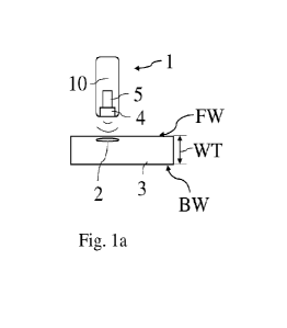
Figure la shows a schematic view of a sensor system 1 according to a first
embodi-
ment. The sensor system 1 is suitable for detecting defects 2 of a pipeline
wall 3. The
pipeline wall 3 is made of metal, for example of steel. The sensor system 1
comprises
a transmitter unit 4 and a control unit 5. The transmitter unit 4 and the
control unit 5
are integrated in a common physical unit 10. The transmitter unit 4 is
configured to
- 16 -
7627099
CA 03163397 2022- 6- 29
emit ultrasound and receive ultrasound, which is reflected in the form of
ultrasonic ech-
oes from a pipeline wall 3.
The transmitter unit 4 is configured to emit and detect high-frequency
ultrasound. Here,
the transmitter unit 4 emits high-frequency ultrasound with a frequency in a
range from
3 to 5 MHz. Thus, the sensor system 1 detects, for example, corrosion or
detachment
of coatings in liquid-carrying pipelines, which are, for example, oil-carrying
or water-
carrying.
Alternatively, the transmitter unit 4 is designed to emit and detect low-
frequency ultra-
sound. Here, the transmitter unit 4 emits low-frequency ultrasound with a
frequency in
a range from 500 to 600 KHz. Thus, the sensor system 1 detects, for example,
corro-
sion or detachment of coatings in gas- or liquid-carrying pipelines. For
example, gas
with a pressure of 107 Pa may be present in the pipeline.
In the following, the reference signs 4A, 4B, 4a, 4b are also assigned for the
transmitter
unit 4. The latter reference signs refer to a structural form of the
transmitter units 4, 4A,
4B, 4a, 4b, wherein all transmitter units 4, 4A, 4B, 4a, 4b can be driven as a
first or as
a second transmitter unit.
Figure lb shows a schematic view of a sensor system 1 according to a second em-
bodiment. The sensor system 1 of the exemplary embodiment of Fig. lb is
suitable for
detecting corrosion, cracks and detachments of coatings at or in a pipeline
wall 3,
which is liquid-carrying.
The sensor system 1 comprises two physical units 10, which are spatially
separated
from each other. The physical units 10 can be fixed to each other at a
distance of, for
example, 5 cm, or be designed to be movable relative to each other. The
physical units
10 of the sensor system 1 each comprise a control unit 5 and a transmitter
unit 4A, 4B.
Alternatively, according to an embodiment not shown, a common control unit 5
may be
provided for both transmitter units 4A, 4B. The control unit 5 needs not be
integrated
- 17 -
7627099
CA 03163397 2022- 6- 29
within one of the physical units 10 of the sensor system 1. In the embodiment
two
physical units 10 respectively comprising a transmitter unit 4A, 4B are shown.
How-
ever, more than these two physical units 10 comprising a respective
transmitter unit
can be provided.
The transmitter units 4A, 4B are driven differently by the control unit 5: The
first trans-
mitter unit 4A is driven to operate in a pulse echo mode (PE mode), and to
operate in
a pitch catch mode (PC mode). In addition, the first transmitter unit can be
driven sim-
ultaneously in the pitch catch mode and in the PE mode (see also explanations
with
respect to the flow chart in Fig. 3). The PC mode is also abbreviated as "PC"
below
and the PE mode is also abbreviated as "PE" below. In both modes PE, PC
described
above, the first transmitter unit 4A emits ultrasound towards the pipeline
wall 3 and
detects ultrasonic echoes reflected from the pipeline wall 3. The second
transmitter
unit 4B is driven in the PC mode (see also explanations with respect to Fig.
3) to detect
the ultrasonic echo reflected from the pipeline wall 3.
The control unit 5 is operated in both modes PE and PC. The control unit 5
evaluates
signals corresponding to the ultrasonic echoes in order to detect a defect 2
of the pipe-
line wall 3 based on a change in the ultrasonic echo occurring in the PE, PC
mode.
When the pipeline wall 3 is intact, the first transmitter unit 4A detects in
the PE mode
the majority of the ultrasound emitted normally onto the pipeline wall
surface, which is
reflected as an echo. A minor portion of the ultrasonic echo is detected by
the second
transmitter unit 4B in the PC mode. In the case of corrosion, the first
transmitter unit
4A detects a significant change in the ultrasonic echo in the PE mode. The
second
transmitter unit 4B, too, detects a change in the ultrasonic echo in the PC
mode. The
detected signal changes in the PE and PC modes are each sufficient to
determine that
corrosion is present. In the case of a crack in the pipeline wall 3, for
example in the
form of a linear defect, a change in the ultrasonic echo is detected in the PC
mode. In
detecting the change in the ultrasonic echo, it is taken into account that an
ultrasonic
echo generated by ultrasound emitted from the transmitter unit(s) is partially
- 18 -
7627099
CA 03163397 2022- 6- 29
suppressed by the crack, and is partially generated by ultrasound reflected at
the crack.
In the case where the crack is located between the transmitter unit 4 emitting
the ul-
trasound and the transmitter unit 4 detecting the ultrasound, the detected
signal of the
ultrasonic echo is reduced. In the case where the emitting and detecting
transmitter
units 4 together approach the crack, a detected ultrasonic echo signal
increases com-
pared to an ultrasonic echo signal generated at an intact pipeline wall
surface. The
transmitter units 4, 4A, 4B may include a low noise, high gain amplifier (not
shown).
This can be used in both modes PE, PC.
The transmitter units 4, 4A, 4B of the embodiments described above and below
are
piezoelectric broadband transmitters. The physical units 10 of the sensor
system 1
may, as an alternative to an embodiment comprising one transmitter unit 4A, 4B
per
physical unit 10, each be configured in accordance with one of the exemplary
embod-
iments of Figures 2a to 2c. Figures 2a to 2c each show a schematic top view of
an
ultrasonic entrance/exit surface of a physical unit 10 of a sensor system 1
according
to a third to fifth embodiment. In these exemplary embodiments, ultrasound
emitting
and ultrasound detecting transmitter units 4a, 4b are integrated in the
physical unit 10.
The transmitter units 4a, 4b can operate as a first or a second transmitter
unit 4 de-
pending on the operation mode in the PE mode or PC mode.
According to the embodiment shown in Figure 2a, the physical unit 10 comprises
an
emitting transmitter unit 4b and a detecting transmitter unit 4a.
According to an exemplary embodiment of Figure 2b, the physical unit 10
comprises a
plurality of ultrasound emitting transmitter units 4b and an ultrasound echoes
detecting
transmitter unit 4a arranged centrally with respect to the ultrasound emitting
transmitter
units 4b.
According to an exemplary embodiment shown in Figure 2c, a physical unit 10
com-
prises a detecting transmitter unit 4a and an emitting transmitter unit 4b
annularly sur-
rounding the detecting transmitter unit 4a. In other words, the second
transmitter unit
- 19 -
7627099
CA 03163397 2022- 6- 29
4b is formed by a one-piece ring at its ultrasound exit surface, and an
ultrasound en-
trance surface of the first transmitter unit 4a is disposed inside the ring.
Alternatively or additionally, physical units 10 according to the exemplary
embodiment
of Figure 2a or 2c are arranged to each other (circularly) in a configuration
as shown
in Figure 2b. The number of detecting transmitter units 4a arranged in the
center and/or
of emitting transmitter units 4b arranged in the circle is adaptable as
required according
to a signal-to-noise ratio to be achieved, the characteristics of the pipeline
and a size
of the sensor system 1. The emitting transmitter units 4b may also be arranged
in a
plurality of circles of different diameters around the detecting transmitter
unit(s) 4a.
Alternatively to the above exemplary embodiments, the detecting transmitter
units 4a
are arranged in circles around one or more ultrasound emitting transmitter
unit(s) 4b.
This may be realized in one physical unit 10 or in multiple physical units 10
according
to the principles described above.
According to one exemplary embodiment, the transmitter units 4, 4a, 4A, 4B, 4b
emit
or detect ultrasound in the high frequency range. According to an alternative
exemplary
embodiment, the transmitter units 4, 4a, 4A, 4B, 4b emit or detect ultrasound
in the
low-frequency range. Alternatively, the sensor system 1 comprises physical
units 10
which emit or detect ultrasound in the high-frequency range and physical units
10
which emit or detect ultrasound in the low-frequency range.
A flow chart of a method for detecting a defect 2 and for characterizing a
wall thickness
WT of the pipeline wall 3 is shown in Fig. 3. The method comprises the
following steps:
According to a step "S100", operating at least one transmitter unit 4, 4a, 4A,
4b, 4B is
implemented to emit ultrasound toward the pipeline wall 3 and detect an
ultrasound
echo reflected from the pipeline wall 3. According to a step "S200", operating
of a
control unit 5 signally connected to the at least one transmitter unit 4, 4a,
4A, 4b, 4B is
implemented to detect a defect 2 of the pipeline wall 3 based on an occurring
change
of the ultrasonic echo.
- 20 -
7627099
CA 03163397 2022- 6- 29
Operating (S100) the transmitter unit 4, 4a, 4A, 4b, 4B may include both the
PE mode
and the PC mode. The PE mode is advantageous for detecting corrosion by use of
one
physical unit 10, see Fig. la, or when only one physical unit 10 is used in
the sensor
system 1 of the exemplary embodiment of Fig. lb. In the PE mode, one of the
trans-
mitter units 4a, 4b of the exemplary embodiments of Figures 2a to 2c or the
combina-
tions of physical units described in this context can be operated, too.
The PC mode occurs in the context of operating at least two transmitter units
4a, 4A,
4b, 4B. These may, for example, be operated in separate physical units 10 (see
Fig.
lb) or in one physical unit 10 (see Figures 2a and 2c and the explanations in
this
context) in the PC mode. As an example, the following method comprising the
following
steps may be used:
Step "S100" comprises operating at least a first transmitter unit 4, 4a, 4A,
4b, 4B ac-
cording to the PE mode and according to the PC mode to emit ultrasound toward
a
pipeline wall 3 and to detect an ultrasound echo reflected from the pipeline
wall 3.
Further, operating at least one second transmitter unit 4, 4a, 4A, 4b, 4B in
the PC mode
is provided to detect the ultrasonic echo reflected from the pipeline wall 3.
Step "S200" comprises operating a control unit 5 signally connected to the
transmitter
units 4, 4a, 4A, 4b, 4B to detect a defect 2 of the pipeline wall 3 based on
an occurring
change in the ultrasonic echo.
In determining the wall thickness WT and characteristics of defects 2 of the
pipeline
wall 3, the control unit 5 utilizes the time course of a frequency signal
which is output
to the control unit 5 by the transmitter units 4, 4a, 4A, 4b, 4B. The
frequency signal is
evaluated either directly or after applying a Fourier transformation several
times (either
in a frequency domain or in a time domain).
When operating the control unit 5 (S200) to detect defects 2, various methods
may be
used:
- 21 -
7627099
CA 03163397 2022- 6- 29
The control unit 5 may use a method for detecting corrosion (indicated by
"K"). To this
end, the control unit 5 is configured to evaluate the change in the ultrasonic
echo cor-
responding to a change in an ultrasonic echo divergence generated by corrosion
in
order to detect corrosion.
Alternatively or additionally, the control unit 5 is configured to carry out a
method for
determining the wall thickness WT (indicated by "WT1" in the flow chart). The
method
WT1 is carried out by the control unit 5 to evaluate data obtained from
measurements
by use of one/more transmitter units 4, 4a, 4A, 4b, 4B which emit high
frequency ultra-
sound. The control unit 5 determines the wall thickness WT (see Figures la and
lb)
of the pipeline wall 3 based on a difference between an inner wall echo time
(TFwE)
and an outer wall echo time (TBwE). The inner wall FW (see Figures la and lb)
is a
surface of the pipeline wall 3 facing the transmitter unit 4, 4a, 4A, 4b, 4B.
The outer
wall BW (see Figures la and lb) is a surface of the pipeline wall 3 facing
away from
the transmitter unit 4, 4a, 4A, 4b, 4B, which is outside the pipeline. A first
detected
inner wall echo may be used in determining the wall thickness WT. The wall
thickness
WT may alternatively or additionally be determined by use of a second or
further de-
tected inner wall echo. The wall thickness WT can then be derived from the
following
formula:
WT¨
cu(TBwE- TFwE)
2
Here, CL2 is the speed of sound in the pipeline wall.
Alternatively or additionally, the control unit 5 is configured to carry out a
method for
determining the wall thickness WT (indicated by "WT2" in the flow chart). The
method
WT2 is carried out by the control unit 5 to evaluate data obtained from
measurements
by use of one/a plurality of transmitter units 4, 4a, 4A, 4b, 4B emitting low
frequency
ultrasound. Here, the control unit 5 is configured to determine a wall
thickness WT of
the pipeline wall 3 based on resonance frequencies fl, f2, ...fi of the outer
wall echo.
- 22 -
7627099
CA 03163397 2022- 6- 29
Here, the control unit 5 determines resonance frequencies fl, f2, ..., fi of
the outer wall
echo in a frequency domain. The wall thickness WT then results from
WT-2(
f2
L-2t)1
Here, CL2 is the speed of sound in the pipeline wall. The resonance frequency
f2 of the
outer wall echo is the resonance frequency following in time the resonance
frequency
fl of the outer wall echo. Alternatively or in addition to the frequencies fl
and f2, other
resonance frequencies fi obtained from the Fourier transform can be used to
determine
the wall thickness WT.
The method of the control unit 5 described below is denoted by "WT3" in the
flow chart.
Accordingly, a signal-to-noise ratio may be improved by carrying out a second
degree
Fourier transform on the detected signal. Such a Fourier transform may be
carried out
for signals from transmitter units 4, 4a, 4b, 4A, 4B operated both at high-
frequency and
at low-frequency. Here, a wall thickness WT is determined on the basis of a
period
duration Ti, T2, ..., Ti of the outer wall echo time TBWE of an ultrasonic
signal trans-
formed by means of a second degree Fast Fourier transform (F FT). Here,
preferably a
maximum amplitude of the signal of the outer wall echo is used for determining
the wall
thickness. The wall thickness WT is then obtained, for example, taking into
account a
period duration Ti of the maximum amplitude of the outer wall echo signal:
WT¨CL2T1
2
Alternatively or additionally, the control unit 5 is configured to carry out a
method for
determining crack characteristics ("crack detection", abbreviated as "CD" in
the flow
chart). The method CD is carried out by the control unit 5 to evaluate data
obtained
from measurements by use of one/a plurality of transmitter units 4, 4a, 4A,
4b, 4B
which emit low-frequency or high-frequency ultrasound. Here, the control unit
5 is con-
figured to carry out crack detection and a crack size determination based on
amplitudes
- 23 -
7627099
CA 03163397 2022- 6- 29
from the resonance frequencies fl, f2, ...fi and (an) amplitude(s) of an outer
wall echo.
In particular, the control unit 5 is configured to carry out crack detection
and a crack
size determination based on amplitudes of resonance frequencies fl, f2, ...fi
in a fre-
quency domain and (an) amplitude(s) of an outer wall echo of an ultrasonic
signal
transformed by second degree FFT. In the aforementioned method of
investigating
crack characteristics, an attenuation of the ultrasound echo is proportional
to a depth
of the defect 2.
The aforementioned exemplary embodiments are suitable for wall thickness
determi-
nation of pipelines with thicknesses from 6 mm to 30 mm. Other wall
thicknesses WT
are also conceivable.
- 24 -
7627099
CA 03163397 2022- 6- 29
List of reference symbols
1 sensor system
2 defect
3 pipeline wall
4, 4a, 4b, 4A, 4B transmitter unit
5 control unit
physical unit
BW outer pipeline wall
10 CD crack characterization method
FW inner pipeline wall
PC PC mode
PE PE mode
WT wall thickness
WT1 first method for wall thickness determination
WT2 second method for wall thickness determination
WT3 third method for wall thickness determination
S100 operating at least one transmitter unit
S200 operating at least one control unit
- 25 -
7627099
CA 03163397 2022- 6- 29