Note: Descriptions are shown in the official language in which they were submitted.
Rotor System for an Aircraft
The invention relates to a rotor system for an aircraft.
The operation of rotor systems causes acoustic emissions that can be perceived
as
disturbing in terms of both volume and frequency. For applications of rotor
systems for
aircrafts operating in the vicinity of residential areas, measures are
accordingly taken
to reduce the sound level emitted into the environment per se or at least for
certain
frequencies.
In order to reduce the acoustic emissions of a rotor system, it is known, for
example,
to provide an aeroacoustic liner as well as an aerodynamic liner. The
aeroacoustic
liner reduces the sound generated by the rotor in general, while the
aerodynamic liner
is aimed at reducing the acoustic emissions induced by the rotor blade tip
vortices.
For this purpose, EP 2 913 269 Al proposes with regard to a tail rotor of a
helicopter
to arrange an aerodynamic liner in the form of a separate channel in the area
of the
rotor plane. An aeroacoustic liner is also arranged on the air discharge side
of the
rotor and is formed by interlinked or nested hollow structures. However, this
prior art
has several disadvantages. For example, the arrangement of the aeroacoustic
liner
next to the aerodynamic liner requires a corresponding installation space in
the axial
direction with respect to the axis of rotation of the rotor. In addition, the
effect of the
aeroacoustic liner is limited to the area of the air discharge side, so that
acoustic
emissions on the air intake side of the rotor are not reduced or are reduced
only to a
limited extent. In particular, the aeroacoustic liner cannot be implemented in
a
continuous manner, since the stators or supporting struts of the rotor are
located in the
area of the aeroacoustic liner. Ultimately, however, the weight of the tail
rotor system
is also increased due to the additional structures introduced to form the
separate
channel for the aerodynamic liner and for the interlinked or individual nested
hollow
structures of the aeroacoustic liner.
KOP 5/DH/CE/J uly 01, 2022
x
CA 03163822 2022- 7-5
2
In view of the disadvantages associated with the prior art, it is an object of
the present
invention to provide a rotor system for an aircraft, which includes an
aerodynamic liner
as well as an aeroacoustic liner in compact design to reduce sound emissions.
The object underlying the invention is solved by a rotor system for an
aircraft
according to claim 1. Further advantageous aspects of the invention become
apparent
from the dependent claims.
Therein, the invention is generally applicable to rotor systems for aircrafts.
In
particular, the invention may be applied to tail rotors of a helicopter.
According to the invention, the rotor system for an aircraft comprises a rotor
capable
of being driven and comprising multiple rotor blades disposed in a
substantially radial
manner about an axis of rotation of the rotor, wherein a plane perpendicular
to the axis
rotation and extending through the rotor blades in a radial direction forms a
rotor
plane, and a rotor shroud, which surrounds the rotor circumferentially with
regard to
the axis of rotation and which confines an air channel of the rotor extending
in an axial
direction of the axis of rotation, wherein the rotor shroud forms a hollow
structure
extending circumferentially with regard to the axis of rotation, wherein the
hollow
structure has on its circumferential face facing the rotor in the radial
direction at least
in a section thereof an area permeable to gas, wherein the rotor plane
intersects the
area permeable to gas, and wherein the hollow structure is configured such
that
acoustic waves of at least one frequency penetrating through the area
permeable to
gas into the hollow structure are at least partially absorbed by the hollow
structure.
The phrase "substantially radial" with respect to the arrangement of the rotor
blades
refers to the base direction of the rotor blades. However, it is not mandatory
that these
are formed strictly radial. For example, the rotor blades may have an angle of
attack
with respect to a geometrical radius, wherein the base direction is still
radial in the
meaning of a radiant arrangement of the rotor blades about the axis of
rotation.
Moreover, the rotor blades need not be arranged at equal distances, but can
have
mutually distinct distances, such as to transfer acoustic energy to multiple
frequencies,
for example.
CA 03163822 2022- 7-5
3
The rotor shroud forms the areodynamic liner as well as the aeroacoustic liner
via the
hollow structure in cooperation with the area permeable to gas formed at least
in a
section thereof. In other words, the aerodynamic and aeroacoustic liners are
formed
via the primary structure of the rotor shroud without necessitating further
separate
elements of the shroud. The term primary structure is used herein to clarify
that the
rotor shroud used to form the hollow structure does not refer to other
additional
structural elements not belonging to the rotor shroud per se, but to the
elements of the
outer shell actually intended to form the shroud. Accordingly, the hollow
structure is
formed by inner side surfaces arranged opposite to the corresponding outer
side
surfaces of the shroud. In other words, the hollow structure is formed by
those
elements of the shroud which constitute the outer shell of the rotor shroud.
Thereby,
an acoustic wave penetrating the area permeable to gas is led into a space
which
extends radially with respect to the axis of rotation up to an opposite inner
side of the
rotor shroud, or primary structure, respectively. In view of the rotor shroud
extending
circumferentially with respect to the axis of rotation, also the hollow
structure similarly
turns out to extend circumferentially. This arrangement is continuous, without
addition
of further stiffening elements and/or hollow space elements to be described
below.
Consequently, the hollow structure formed by the rotor shroud in itself
results in a
globally acting hollow structure. In other words, the hollow space formed by
the hollow
structure extends continuously in the circumferential direction. It can be
adapted to a
locally acting hollow structure for example by reference to the aforementioned
and still
to be described stiffening elements and/or hollow space elements. However,
this
pertains to a specific embodiment of the invention. Even under consideration
of further
structural elements arranged in addition to the rotor shroud, the absorption
characteristics with regard to the acoustic waves penetrating through the area
permeable to gas are determined by the rotor shroud itself.
It is preferred that the area permeable to gas is not only formed in sections
in the
circumferential direction. Rather it is formed throughout the circumference
such as to
act in cooperation with the hollow structure over the entire the circumference
in the
circumferential direction. This already results from the rotation of the rotor
blades
alone, which, according to their movement, initially do not show any local
sound
CA 03163822 2022- 7-5
4
emission and/or rotor blade tip vortex maxima. In interaction with other
structural
components of the rotor system and/or in connection with the arrangement
and/or
angle of attack of the rotor blades, those maxima may, however, indeed occur
locally,
such that providing one or more areas permeable to gas in sections may be
sufficient.
In terms of the mode of action of an aerodynamic liner of the rotor shroud,
the rotor
blade tip vortices strike the area permeable to gas located in the rotor plane
on the
circumferential face facing the rotor blades when the rotor is in operation.
The rotor
blade tip vortices may penetrate through the area permeable to gas, and are at
least
partially absorbed therein, in particular dissipated. Those rotor blade tip
vortices which
do not penetrate into the hollow structure are at least scattered. Besides the
acoustic
effects, the at least partial reduction of the rotor blade tip angles, caused
for example
by dissipation, may also exert an effect on the aerodynamic resistance, and
may thus
increase the overall thrust generation.
However, acoustic waves similarly also penetrate through the area permeable to
gas
into the hollow structure, wherein the hollow structure absorbs acoustic waves
of at
least one frequency at least partially and thus acts as an acoustic linier.
Basically, in
this context the terms absorption and damping of acoustic waves may be used as
synonyms. Thereby, dissipation for example represents a concrete form of
absorption
or damping by conversion of energy. The frequencies that occur at a
predetermined
rotational speed of the rotor are constant. However, the amplitude of the
respective
frequency may be variable in dependence of the current settings of the rotor
system,
for example in dependence of the angle of attack of the rotor blades. Hence,
the
hollow structure may for example be adapted for an at least partial absorption
of the
frequency or frequencies, which is/are considered as particularly distracting,
even if
these do not necessarily cause a largest sound level. The provision of the at
least
partial absorption characteristic of the hollow structure may be realized
geometrically,
or alternatively or even supplementary by means of a suitable selection of
materials.
By positioning the combined aerodynamic and aeroacoustic liner in the rotor
plane, an
implementation over the entire circumference of the rotor shroud without
interruptions
becomes possible.
CA 03163822 2022- 7-5
5
The aforementioned rotor system thus necessitates a reduction of the
aerodynamic
effects of the rotor blade tip vortices over the area permeable to gas, an at
least partial
absorption and thus damping of penetrating acoustic waves, by the combination
of the
area permeable to gas with the hollow structure, as well as a positive
influence on the
efficiency of thrust generation. Since a modification of the outer contour of
the rotor
shroud is not needed, even the aerodynamic effect of the rotor shroud for
thrust
generation is maintained. However, depending on the frequency to be damped,
the
rotor shroud can also be adjusted, taking into account the aerodynamic effect.
However, alternative or complementary measures can be taken, which relate to
the
space within the hollow structure, as will be described below with regard to
additional
elements and/or material structures.
In one embodiment, a circumferential face of the hollow structure opposite the
area
permeable to gas on a side facing away from the rotor blades is spaced apart
in such
a way that the area permeable to gas forms, at least in sections, a lambda
quarter
resonator for the at least one frequency with the opposite circumferential
face.
The circumferential face of the hollow structure facing the area permeable to
gas on a
side away from the rotor blades can also be referred to as the outer
circumferential
inner surface. In contrast to this, the inner side of the circumferential face
facing the
outer circumferential inner surface and having the area permeable to gas would
be an
inner circumferential inner surface. By spacing the outer and inner
circumferential
inner surfaces according to a lambda quarter resonator, a standing wave or
multiples
of the quarter wavelength (harmonics) of a corresponding wavelength or
frequency or
mode combination can be formed in the hollow structure. In combination with
the area
permeable to gas, which represents an acoustic resistance in this case, the
acoustic
energy is at least partially converted into thermal energy for corresponding
frequencies, which represents absorption. The distance can be constant in the
circumferential direction or can also vary at least in sections in the
circumferential
direction in order to be tuned locally to different frequencies. Such tuning
can
alternatively or additionally also be provided perpendicular to the direction
of rotation,
CA 03163822 2022- 7-5
6
i.e. with respect to the axis of rotation in the axial direction. This proves
to be
particularly advantageous if different maxima of certain frequencies can occur
in the
axial direction, as can possibly result from different angles of attack of the
rotor
blades, which will be discussed below. The spacing of the outer and inner
circumferential surfaces can be formed by appropriate arrangement of the rotor
shroud material or also by appropriate material contouring. Material contours
can, for
example, be variations of the material cross-section so that the outer and
inner
circumferential inner surfaces can have locally different distances despite
the material
being spaced parallel to each other.
Alternatively or additionally, the hollow structure forms, at least in
sections, a
Helmholtz resonator for the at least one frequency.
The Helmholtz resonator is particularly suitable for absorbing or damping
lower
frequencies. Since medium and higher frequencies are only damped to a limited
extent, the hollow structure may include an arrangement of further resonator
concepts,
such as the arrangement, at least in sections, of a lambda quarter resonator.
Further to the geometric design as a lambda quarter resonator, a Helmholtz
resonator
or a combination thereof or other resonator concepts, the acoustic damping
properties
may also be supported by the specific choice of materials and/or surface
structures.
For instance, structural features of a Helmholtz resonator can be used to
attenuate
lower frequencies and structural features of a lambda quarter resonator can be
used
to attenuate medium and/or higher frequencies.
According to an embodiment, the circumferential hollow structure may be
designed to
be fluid-permeable in the circumferential direction at least in sections which
are
aligned in parallel to the gravitational force in the circumferential
direction.
Liquids, such as precipitation or cleaning water, may penetrate the hollow
structure
through the area permeable to gas or also through other openings in the rotor
shroud.
These may also run off again depending on the position of the respective
openings.
For example, during cleaning, water may enter through a section of the hollow
CA 03163822 2022- 7-5
7
structure that has an area permeable to gas that is spatially oriented such
that the
water runs off in the direction of the gravitational force across the area
permeable to
gas. However, not all sections of the circumferential hollow structure offer
such a
possibility of drainage. In this respect, sections that are oriented parallel
to the
gravitational force in the circumferential direction and thus do not have any
drainage
even via the area permeable to gas in this section should, in particular, be
designed to
be fluid-permeable. The fluid permeability in this case is not aiming at a
drainage
directed outwards, but concerns the fluid conduction in the hollow structure,
so that
penetrating fluids can be led in the hollow structure at least up to a section
that allows
drainage. Since the rotor system according to the invention can be formed
directly via
the primary structure, the internal fluid conduction via the hollow structure
can thus be
realized in a simple manner.
However, the design of the hollow structure that is at least partially fluid-
permeable
also allows the resonator space that may effectively be used to be extended in
the
circumferential direction. For this purpose, it can be assumed that the fluid
permeability in this case also causes a gas permeability. Even if no resonator
cavity is
formed in the sense of a formation of standing waves, at least individual
frequencies
can be damped, for example by dissipation.
It is preferred that the hollow structure comprises at least one drainage
opening.
Liquid that has penetrated the hollow structure can be selectively drained or
ran off via
the drainage opening. The location of the drainage may thus be selected at a
suitable
location and/or the timing of the drainage can be set in advance if the
drainage
opening can be selectively opened and closed. The drainage opening can be
formed
by the area permeable to gas. However, this may be insufficient in some cases
because, for example, the area permeable to gas of a tail rotor of a
helicopter may not
form the lowest point of the hollow structure when it is in a stationary
state.
Accordingly, the area permeable to gas in this case might just act as an
overflow or
spillway, but cannot independently drain fluids from the hollow structure that
are
located below the area permeable to gas. Accordingly, a separate drainage
opening
may be advantageous.
CA 03163822 2022- 7-5
8
In particular, the rotor blades have an angle of attack that is variably
adjustable about
an axis that is radial with respect to the axis of rotation, and the area
permeable to gas
extends axially with respect to the axis of rotation at least over an area
that covers the
rotor blade positions that can be accomplished via the angles of attack.
Depending on the flight nnanoeuvers to be performed, the angle of attack of
the rotor
blades is changed. This also changes the position of the area in which rotor
blade tip
vortices are generated. In order to encompass all area positions of the rotor
blade tip
vortices associated with the angles of attack, the area permeable to gas
extends at
least in sections, in particular in the circumferential direction over the
entire
circumferentially extending surface, and in the axial direction at least over
the area
over which all rotor blade positions can be covered in accordance with the
rotor blade
angles of attack. Otherwise, i.e., with an axial extension of the area
permeable to gas
that does not cover all adjustable rotor blade positions, the aerodynamic
effect of the
area permeable to gas is not present for all rotor blade positions or rotor
blade angles
of attack, or is at least substantially restricted.
Since the propagation of the rotor blade tip vortices in the radial direction
with respect
to the axis of rotation of the rotor is not limited to the area bounded by the
rotor blade
tip, i.e., the rotor blade tip vortices may propagate in an scattering manner
not purely
radially but also in the axial direction, the area permeable to gas in the
axial direction
may in particular be designed to be larger than the overlap area of the rotor
blade
positions. Preferably, the area permeable to gas is, starting from the rotor
plane in the
axial direction outwards, larger at least on one side, more specifically on
both sides,
than the overlap area of the rotor blade positions, which is in relation to
this section, in
accordance with the rotor blade angles of attack.
In one embodiment, the fraction of porosity of the area permeable to gas
ranges from
5% to 90%.
The area permeable to gas is basically defined as the area that has a
predominant
gas permeability compared to other areas of the rotor shroud. The term
CA 03163822 2022- 7-5
9
"predominantly" does not necessarily refer to a gas permeability of more than
50%,
but to a material property that can be identified as gas-permeable. The area
is thereby
confined via the outermost gas-permeable openings, such as pores, beyond which
the
rotor shroud transitions into a gas-impermeable material area.
Thus, if the area permeable to gas is formed by pores, the proportion of the
void
volume, i.e., the volume of all pores in this area, to the total volume of
this area is from
5% to 90%. With a lower proportion of the void volume, the rotor blade tip
vortices are
predominantly reflected and no longer introduced into the hollow structure.
Thus, the
aerodynamic liner no longer operates effectively. Likewise, the acoustic
bandwidth of
the lambda quarter resonator suffers and at the same time there is a shift in
the mode
of action of the liner from a lambda quarter resonator in the direction of a
Helmholz
resonator for very low frequencies, which are no longer relevant for the
audible range.
With a proportion of more than 90% of the cavity volume, the absorption or
damping
capacity can be significantly reduced if rotor blade tip vortices and/or
acoustic waves
penetrating through the pores can escape again without significant damping.
According to an embodiment, the porosity varies starting from the rotor plane
in the
axial direction in relation to the axis of rotation. In particular, the
porosity increases
starting from the rotor plane towards at least one side in the outward
direction.
By changing the porosity in the axial direction, the acoustic impedance and
thus the
acoustic behavior of the aerodynamic and aeroacoustic liner can be locally
adjusted.
This may be particularly advantageous for rotor blades with adjustable angles
of
attack, since the frequency amplitudes shift with varying the angles of
attack.
Preferably, a larger porosity, i.e., a larger void volume, is to be provided
in the outer
regions of the area permeable to gas, which are relevant to the effect at
larger angles
of attack of the rotor blades. The change in porosity can be expressed as
porosity per
unit area.
Alternatively or complementarily, the porosity changes in the circumferential
direction
of circulation of the area permeable to gas.
CA 03163822 2022- 7-5
10
A porosity varied in the circumferential direction allows adjusting the
impedance and
thus the acoustic behavior along the circumference. Consequently, the
interaction of
sound emission with various structural elements along the circumference can be
taken
into account, even under a possible consideration of adjustable angles of
attack of the
rotor blades
By a combination of porosity varied in the axial direction as well as in the
circumferential direction, the acoustic properties can be optimized both
structurally
and operationally.
In one embodiment, the area permeable to gas is formed by microperforation, a
perforated metal plate and/or a wire mesh.
Microperforation of a rotor shroud profile or a section thereof is able to
introduce a gas
permeability to the area permeable to gas without necessitating structural
disruption.
Furthermore, the distribution of the microperforation can be implemented
precisely as
needed. The separate insertion of a perforated plate and/or a wire mesh allows
flexible adjustment of the acoustic behavior by replacing the respective
insert.
Furthermore, in such a case it is possible to take advantage of different
material
properties independently from the material of the actual rotor shroud.
According to a further embodiment, the hollow structure has stiffening
elements and/or
hollow structural elements which, in their position and/or design, have a
sound-
absorbing effect or promote sound absorption.
Stiffening elements, which are used specifically for stabilization, or also
other hollow
structure elements, which serve, for example, as a line or pipe guide, may
thus also
be used to improve the sound-absorbing or/and sound-absorbing properties of
the
rotor system. This also makes it possible to dispense with additional
components and
structures intended solely for sound absorption.
The positioning may be performed in the circumferential direction as a
function of the
frequency to be at least partially absorbed, for example due to the natural
frequencies
CA 03163822 2022- 7-5
11
of the gas volume enclosed inside the overall structure or inside acoustically
separated subspaces. Alternatively or complementarily, the positioning in the
circumferential direction may also be performed as a function of the local
interaction of
the acoustic emissions with respective structural components. By means of the
positioning, the depth and/or the volume of the hollow structure may thus be
influenced via the stiffening elements and/or hollow structural elements in
order to
specifically increase the at least partial absorption of at least one
frequency.
Accordingly, this also makes it possible to transfer a globally acoustically
effective
hollow structure, such as one that may be formed by a structure that is
continuous in
the circumferential direction without stiffening elements and/or hollow
structural
elements, into a locally acoustically effective hollow structure.
In contrast, the design of the stiffening elements and/or hollow structural
elements
refers to the concrete geometric design, such as the contour or material
thickness, the
material to be used and/or various surface properties, such as can be
implemented via
coatings or surface texturing.
In particular, the hollow structure may absorb substantially penetrating
acoustic waves
in a broadband frequency range.
The broadband design relates significantly to the effect of the structure as
an
aeroacoustic liner, which is further supported by variable depths of the
hollow
structure, i.e., spacings in the radial direction with respect to the axis of
rotation.
Furthermore, the appropriate choice of the perforation of the area permeable
to gas
may increase the bandwidth at the expense of the absolute absorption of the
liner.
In one embodiment, the hollow structure at least partially absorbs
substantially
penetrating acoustic waves in a frequency range from 30 Hz to 1500 Hz.
In this frequency range, precisely those frequencies occur which are also
perceived as
particularly disturbing. In particular, however, this frequency range also
includes
frequencies with amplitude maxima that are usually clearly perceptible.
Accordingly,
the overall volume level can be lowered if a suitable choice is made.
CA 03163822 2022- 7-5
12
According to an embodiment, the rotor system comprises at least one support
strut
arranged on an air intake side of the rotor system.
Support struts, which are sometimes also referred to as a stator, serve to
suspend the
rotor hub. These are usually arranged on the air discharge side of a rotor
system,
whereby the air duct, which is wider in the axial direction with respect to
the axis of
rotation and is formed by the rotor shroud, compensates for the sound
emissions
associated with this arrangement. However, if the at least one supporting
strut for
suspending the rotor hub is now arranged on the air intake side, the sound
emissions
otherwise caused by the impact of the air accelerated by the rotor on the
supporting
strut are reduced. In other words, a further source of sounds on the air
discharge side
is avoided, so that the axial width of the air duct can be reduced. The air
intake side is
understood to be the side on which air is drawn in for the majority of the
flight
manoeuvers. Similarly, the air discharge side is the side on which air is
discharged for
the majority of the flight manoeuvers.
Preferably, the at least one supporting strut is arranged eccentrically, or
off-center,
with respect to the axis of rotation.
The eccentric arrangement supports the reduced sound emission due to the time-
shifted interaction between the wake in the velocity profile of the incident
flow caused
by shadowing effect of the supporting strut and the leading edge of the
rotating rotor
blades in regular operation, i.e., for torque compensation of the main rotor.
In case of
negative angles of attack of the rotor blades due to manoeuvers of the flying
machine,
there is also no simultaneous interaction, In this regard, however, the
interaction
between the vortices induced by the rotating rotor blades and the supporting
struts,
which are responsible for a sound generation, is meant.
Features, usefulness and advantages of the invention are also described below
with
reference to the drawings by way of embodiments.
In the drawings,
CA 03163822 2022- 7-5
13
Fig. 1 shows a schematic representation of an aircraft having a
rotor system in
accordance with an exemplary embodiment of the invention;
Fig. 2 shows a perspective view of the rotor system of Fig. 1;
Fig. 3 shows a perspective cross sectional view of the rotor
system of Figs. 1 and 2
in sectional plane parallel to the axis or rotation;
Fig. 4 shows a schematic cross sectional view of the rotor system according
to Fig.
3 with a direction of view onto the sectional plane and representation of the
positional
range of the rotor blades;
Fig. 5 a perspective cross-sectional section of the rotor system
according to figures
1 and 2 in a sectional plane perpendicular to the axis of rotation.
Fig. 1 shows an aircraft 1, in this case a helicopter, having a rotor system
10, which in
the embodiment shown is used as the tail rotor system of the helicopter. The
rotor
system 10 comprises a rotor 20 having rotor blades 21 arranged around a rotor
hub
23 supported by preferably a plurality of support struts 22, and a rotor
shroud 30. The
support struts 22 are arranged on an air intake side 41 (Fig. 2) to avoid
another sound
source on an air discharge side 42 (Fig. 2). In addition, an eccentric
arrangement of
the supporting struts 22 with respect to the axis of rotation R is provided,
which also
has a positive acoustic effect. The air intake side 41 and the air discharge
side 42 are
respectively the sides on which the air is drawn in and discharged for a
predominant
part of the flight manoeuvers. In other words, air can also be discharged on
the air
intake side 41 if the angle of attack of the rotor blades 21 is
correspondingly negative,
although this is only to be assumed in a few cases during flight operation, so
that such
cases are negligible for the definition of the air intake side 41. This
applies equally to
the air discharge side in the reverse constellation.
According to Fig. 2, the rotor shroud 30 surrounds the rotor 20 in the
circumferential
direction with respect to the axis of rotation R and confines an air duct 40
of the rotor
CA 03163822 2022- 7-5
14
20 extending in the axial direction of the axis of rotation R. As a result of
the rotation of
the rotor blades 21 about the axis of rotation R, air is conveyed from the air
intake side
41 to the air discharge side 42, which can also be referred to as the thrust
side. The
air flow direction is also illustrated again in Fig. 2 by the arrows inserted
therein,
although this can also be reversed depending on the setting of the rotor
blades. As
can further be seen from Fig. 4, in the rotor plane RA formed by the rotor
blades 21
perpendicular to the axis of rotation R, the circumferential face 32 of the
rotor shroud
30 facing the rotor 20 has an area permeable to gas 32a which is intersected
by the
rotor plane RA and extends axially to both sides of the rotor plane RA with
respect to
the axis of rotation R. The area permeable to gas 32a is formed by the rotor
blades
21.
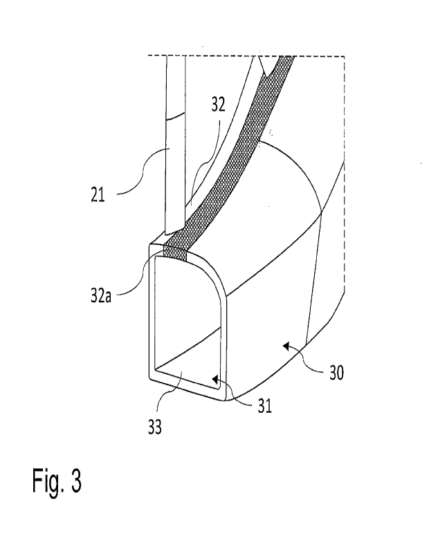
Fig. 3 shows in more detail a perspective cross-sectional section of the rotor
system
10 according to Figs. 1 and 2 in a sectional plane parallel to the axis of
rotation R. In
this exemplary embodiment, the area permeable to gas 32a is formed by a
perforated
metal plate with microperforations, which is inserted and fixed in the rotor
shroud 30.
The porosity introduced by the microperforations amounts to, for example, 50%
and is
constant in the circumferential direction as well as in the axial direction
with respect to
the axis of rotation R. However, the porosity may also vary in the
circumferential
direction as well as in the axial direction with respect to the axis of
rotation R and/or be
less than or greater than 50%. The selection of the porosity or its
distribution can
result from the respective optimization objective with regard to aeroacoustic
or
aerodynamic effects in interaction with a respective structural design.
The area permeable to gas 32a covers the radial projection of the rotor blade
tip of the
rotor blades 21, so that rotor blade tip vortices generated in the gap between
the rotor
blade tips and the area permeable to gas 32a can be introduced through the
area
permeable to gas 32a into the hollow structure 31 formed by the rotor shroud
30 to be
dissipated or otherwise damped, so that an aerodynamic effect is achieved. In
this
regard, the aerodynamic effect refers, on the one hand, to an acoustic effect
by
eliminating or displacing the acoustic sources associated with the rotor blade
tip
vortices into the hollow structure 31. On the other hand, the efficiency of
the rotor
system 10 is increased by the drag reduction caused by the attenuation and/or
CA 03163822 2022- 7-5
15
displacement of the rotor blade tip vortices. In addition, the area permeable
to gas 32a
in combination with the volume formed by the hollow structure 31 implements an
aeroacoustic function in which a purely acoustic effect is also achieved for
acoustic
waves coupled into the hollow structure 31 via the area permeable to gas 32a,
which
are also generated, for example, by components other than the rotor blade tips
during
operation of the rotor 20, by at least partial absorption of at least one
frequency.
For this purpose, in the embodiment shown, the inner surface, which faces the
rotor
20, of the circumferential face 33 facing away from the rotor 20, i.e., an
outer
circumferential inner surface 33a, is spaced apart from the inner surface,
which faces
away from the rotor 20, of the circumferential face 32 facing the rotor 20,
i.e., an inner
circumferential inner surface 32b, in such a way that a lambda quarter
resonator is
formed for at least one frequency.
Accordingly, a combined aerodynamic and aeroacoustic liner is formed by the
positioning and dimensioning of the area permeable to gas 32a in cooperation
with the
volume of the hollow structure 31.
Fig. 4 again shows a schematic cross-sectional view of the rotor system 10
according
to Fig. 3, with a viewing direction towards the sectional plane to illustrate
the
adjustable positional range of angles of attack of the rotor blades 21 and the
overlap
of the rotor blade tips over that range of pitch angle positions by the area
permeable to
gas 32a. For this purpose, Fig. 4 shows the maximum attainable angle positions
of the
rotor blades 21 when rotating about the radial axis X with respect to the axis
of
rotation R for the rotor blade pitch angle. Starting from the rotor plane RA,
which
coincides with the radial axis X, the area permeable to gas 32a extends to
both sides
in the axial direction with respect to the axis of rotation R, the area
permeable to gas
32a covering the maximum pitch angle positions of the rotor blade tips. In the
exemplary embodiment shown, the area permeable to gas 32a is also enlarged
relative to the maximum positions of the rotor blade tips in order to be able
to also
introduce scattered rotor blade tip vortices into the hollow structure.
CA 03163822 2022- 7-5
16
By means of Fig. 5, a perspective cross-sectional section of the rotor system
10
according to Figs. 1 and 2 is exemplarily shown in a sectional plane
perpendicular to
the axis of rotation R. Herein, the rotor shroud 30 forms a hollow structure
31 with
different distances between the outer and inner circumferential surfaces in
the
circumferential direction. Accordingly, locally differing lambda quarter
resonators are
formed so that locally different frequencies can be at least partially
absorbed, which
reduces the overall loudness and confers to the liner a broadband acoustic
effect. In
particular, the different spacings can be provided in such a way as to
preferentially
attenuate tonal components corresponding to the rotational frequency of the
rotor
and/or frequencies otherwise perceived as particularly annoying.
In addition, the hollow structure 31 has various stiffening elements 34 and
hollow
structural elements 35. The stiffening elements 34 serve here, for example, as
stops
and, in terms of their dimensioning and positioning, also influence the
damping of
acoustic waves introduced into the hollow structure and/or propagating
therein,
respectively. Similarly, the additionally introduced hollow structural
elements 35 may
form chambers in the hollow structure 31, for example, in order to form
locally different
resonator volumes in each case and to thereby influence the damping of
frequencies.
Nevertheless, the damping capacity here is largely determined by the primary
structure of the rotor shroud 30.
Referring to Fig. 5, the rotor shroud 30 further has a drainage opening 36
through
which a liquid that has entered the hollow structure 31 can be drained. The
drainage
opening 36 is located in a lower region of the rotor shroud 30 with respect to
the
direction of gravity, in which region a liquid collects due to gravity. For
this purpose,
the hollow structure 31 is preferably circumferentially partially permeable to
fluid, i.e.,
is formed as a continuous circumferential fluid channel. Even if stiffening
elements 34
and/or hollow structural elements 35 are arranged in the hollow structure 31,
these
should then either be at least partially fluid-permeable or be arranged in
positions that
allow a fluid to be discharged or drained in some other way. The latter can be
illustrated by the hollow structural elements 35 shown in Fig. 5. Provided
that these
hollow structural elements are not designed to be fluid-permeable, they are
arranged
at least at positions in which a liquid present in the upper chamber formed by
the
CA 03163822 2022- 7-5
17
hollow structural elements 35 can be discharged via the area permeable to gas
32a
not shown here. The area permeable to gas 32a would thus in this case also be
fluid-
permeable.
The invention is not limited to the embodiment described. In particular,
certain features
of possible variants or further embodiments are in principle also applicable
to other
embodiments, provided that this is not reasonably excluded. For example, even
if the
rotor hub 23 is supported by two support struts 22, only one support strut may
be
provided. Likewise, it is possible to use more than two supporting struts. In
particular,
however, the use of the rotor system 10 is also not limited to a tail rotor
system of a
helicopter, but can also be used for other aircraft, such as drones or air
cabs.
CA 03163822 2022- 7-5
18
List of reference numerals
1 aircraft
rotor system
5 20 rotor
21 rotor blade
22 strut
23 rotor hub
30 rotor shroud
10 31 hollow structure
32 circumferential face (facing the rotor)
32a area permeable to gas
32b inner circumferential surface
33 circumferential face (facing away from rotor)
33a outer circumferential surface
34 stiffening element
35 hollow structural element
36 drainage opening
40 air duct
41 air intake side
42 air discharge side
R axis of rotation
RA rotor plane
X radial axis (rotor blade pitch angle position)
CA 03163822 2022- 7-5