Note: Descriptions are shown in the official language in which they were submitted.
WO 2021/156246
PCT/EP2021/052421
ARRANGEMENT AND METHOD FOR PRETREATMENT OF BIOMASS
TECHNICAL FIELD
The present disclosure generally relates to an arrangement and a method for
pretreatment of lignocellulosic biomass in a reactor vessel having an upstream
inlet for
receiving biomass and a downstream outlet for discharging biomass.
BACKGROUND
Lignocellulosic residues from forestry are attractive as feedstocks for the
production of green chemicals and fuels, since they are abundant, relatively
inexpensive, and
not used for food. Lignocellulose consists mainly of lignin and two classes of
polysaccharides, cellulose and hemicellulose. The polysaccharides can be
hydrolyzed to
sugars and converted to various fermentation products, e.g. bioalcohols, by
means of
fermenting microorganisms, such as Saccharomyces cerevisiae.
The hydrolysis of cellulose is typically preceded by a pretreatment process,
in
which the hemicellulose is degraded, and the cellulose is made more accessible
to cellulolytic
enzymes. During hydrolysis, the cellulose present is partly converted into
reducing sugars.
The pretreatment is considered a critical part in the process of converting
biomass into fermentation products, mainly because it affects downstream
processes and
determines the ultimate sugar yields. A variety of pretreatment processes
exist, many of
which rely on high temperature treatments and high pressures.
The pretreatment process is typically carried out in a pretreatment
arrangement,
such as a pretreatment reactor. The pretreatment reactor generally comprises
an inlet for
receiving the biomass to be pretreated and an outlet for discharging the
pretreated biomass,
and a closed vessel wherein the pretreatment process is carried out.
The overall aim of the pretreatment is to disrupt the crystalline cellulose
structure and to remove or partially remove lignin from the lignocellulosic
biomass. The
pretreatment process is complex and involves many reactions and side-
reactions. Such
reactions may result in the formation of various by-products, which may be
inhibitory to
downstream processes. Furthermore, volatile compounds and gases contained in
the
lignocellulose biomass are set free when the material is degraded or partially
degraded. Gases
may accumulate in a portion of the reactor above the biomass slurry level.
Some pretreatment methods, such as steam explosion, involves deliberately
increasing the pressure and temperature within the reactor. Steam and gaseous
catalysts, such
CA 03163949 2022- 7-6
WO 2021/156246 2
PCT/EP2021/052421
as sulfur dioxide (SO2) or carbon dioxide (CO2) may be added to catalyze the
reaction. The
addition of steam and gaseous catalysts may result in an excess amount of gas
accumulating
in the reactor.
Pretreatment under harsh conditions is associated with problems such as
undesirable fluctuations in the temperature and pressure conditions within the
reactor. The
stability of the process conditions within the reactor is thereby impaired. An
effect of such
imbalanced or unstable reaction conditions is that the pretreatment process
becomes less
efficient, i.e. provides a lower yield. Another effect is that deposits may
form on the reactor
walls.
There is a need for improvements with respect to preventing the formation of
deposits during pretreatment and for overcoming problems with reaction
fluctuations.
Particularly, there is a need to provide a pretreatment system that is stable
and controlled and
which allows for the pretreatment process to be carried out in a consistent
and reliable
manner.
SUMMARY
In view of the above, it is an object of the present invention to provide
improvements with respect to methods and arrangements for pretreatment of
lignocellulosic
biomass, particularly to achieve more stable reaction conditions within the
reactor during
operation and reducing the formation of deposits within the reactor.
According to a first aspect of the present invention, there is provided a
pretreatment arrangement for pretreatment of lignocellulosic biomass material
comprising
a reactor vessel having an upstream inlet for receiving biomass and a
downstream outlet for
discharging the biomass, a gas valve arranged to remove gas from the reactor
vessel and
having an adjustable opening configuration, measuring means arranged for
measuring a
number of process parameters of the pretreatment in the reactor vessel, which
process
parameters include at least a temperature parameter and a pressure parameter,
and gas flow
control means configured to adjust the outflow of gas from the gas valve in
response to the
measured process parameters, whereby a controlled flow of gas out from the
reactor vessel is
achieved.
The present inventive concept is based on the understanding that problems
with unstable pretreatment conditions are mainly related to accumulation of
gases in the
reactor vessel and with the increase of temperature and pressure,
respectively, in the reactor
vessel due to the accumulation of gases.
CA 03163949 2022- 7-6
WO 2021/156246 3
PCT/EP2021/052421
The present invention provides for a controlled removal of gases from the
reaction vessel, through an adjustable gas valve and based on measurements of
the
pretreatment temperature and pressure, resulting in a controlled pretreatment.
The
temperature and pressure have been identified as key parameters, together
sufficient for
achieving stable pretreatment conditions, which implies an efficient
pretreatment and reduced
formation of deposits on the interior walls of the reactor.
According to preferred embodiments, the pretreatment arrangement comprises
gas flow control means configured to adjust the outflow of gas from the gas
valve in response
to the relationship between the temperature and pressure, e.g. expressed as a
ratio between
temperature and pressure, so as to achieve a controlled flow of gas out from
the reactor
vessel.
In other preferred embodiments, the gas flow control means is configured to
determine a ratio between the temperature parameter and the pressure parameter
and adjust
the outflow of gas from the gas valve in response to the determined ratio. The
gas flow
control means may be configured to adjust the outflow of gas from the gas
valve if the
determined ratio deviates from a predetermined reference ratio, e.g. expressed
as an interval,
for the pretreatment.
In embodiments, the gas flow control means is configured to adjust the outflow
of gas from the gas valve if the determined ratio deviates from a
predetermined reference
ratio by more than 5%, such as by more than 10%.
By adjusting the outflow of gas from the gas valve in response to the
relationship between the temperature and pressure, the temperature and
pressure, or the ratio
between temperature and pressure, can be held within a predetermined interval
of deviation
(basically constant, if the interval is comparatively narrow) for the specific
pretreatment to be
carried out
Such pretreatment arrangements will counteract or compensate for imbalance
between the temperature and pressure within the reactor caused by the
liberation of gases
from the biomass during degradation or partial degradation, and which is
particularly
problematic if the pretreatment is carried out by applying steam or additional
catalysts,
particularly gaseous catalysts, leading to an excess amount of accumulated
gases in the
reactor.
In embodiments, the measuring means is configured for monitoring the
process parameters in a continuous or semi-continuous manner and the gas flow
control
CA 03163949 2022- 7-6
WO 2021/156246 4
PCT/EP2021/052421
means is configured to automatically adjust the opening of the gas valve in
response to the
monitored process parameters.
In embodiments, the process parameters measured with the measuring means
further comprise a gas parameter indicating the amount or concentration of gas
in the reactor
vessel.
This allows for a more sophisticated and controlled removal of gases from the
reactor vessel, and thus also a more controlled pretreatment.
In embodiments, the measuring means comprises a flow meter configured to
measure the outflow of gas from the reactor vessel and the gas flow control
means is
configured to adjust the opening of the gas valve also in response to the
measured outflow of
gas.
In embodiments, the reactor vessel is a vertical reactor vessel extending
along
a longitudinal center line and comprising an upper portion and a lower
portion, the gas valve
being arranged in the upper portion of the reactor vessel or outside of the
reactor vessel but in
direct gas communication with the upper portion of the reactor vessel, the
upper portion of
the reactor vessel being above the level of biomass in the reactor vessel when
the
pretreatment arrangement is in operation.
In embodiments, the pretreatment involves steam explosion. The pretreatment
arrangement may be adapted for steam explosion downstream or in an outlet
region, i.e. in or
close to the outlet, of the reactor vessel.
As mentioned, during steam explosion, steam and additional acid catalysts are
added, which may result in an excess amount of gas accumulating in the reactor
vessel. The
incorporation of a gas valve is therefore an efficient means to control the
process fluctuations
within the reactor and to provide a stable and efficient pretreatment.
In embodiments, a pretreatment arrangement with steam explosion comprises
a sluice vessel configured to discharge biomass received from the outlet of
the reactor vessel,
wherein the sluice vessel is arranged in fluid communication with and
downstream of the
reactor vessel. The sluice vessel comprises a separate vessel or compartment,
arranged with
sluice means (valves) so as to be able to have a different pressure than the
pressure within the
reactor vessel.
The sluice vessel secures an improved discharge of pretreated biomass from
the reactor vessel and is particularly advantageous for pretreatment processes
involving
steam explosion. If the pretreatment involves steam explosion, such a process
poses demands
on the equipment utilized. The high temperatures and pressures used within the
reactor may
CA 03163949 2022- 7-6
WO 2021/156246 5
PCT/EP2021/052421
result in the formation of deposits within the reactor, and such deposits may
build up on the
reactor walls. The provision of a sluice vessel allows the biomass to first be
treated in the
reaction vessel under optimum conditions for pretreatment (suitable time,
pressure,
temperature, etc.), and subsequently, the pressure may be increased within the
sluice vessel;
i.e. outside of the reactor vessel. Upon discharge from the sluice vessel, the
pressure drops
and results in division of the material into smaller particles. Accordingly,
the -harsh" process
conditions associated with large pressure variations, are performed separate
from the reactor
vessel, and the burning or charring of sugars and biomass within the reactor
vessel, can be
avoided. The discharge of biomass is therefore performed in a controlled and
improved
manner.
In embodiments, the pretreatment arrangement further comprises a scraping
device configured to scrape deposits formed on the interior walls of the
reactor vessel. The
scraping device may be arranged in the reactor vessel to prevent the formation
of deposits on
the interior reactor walls and to scrape off deposits potentially formed.
According to another aspect of the present invention, there is provided a
method for controlled pretreatment of lignocellulosic biomass, wherein the
method comprises
the steps of:
pretreating a lignocellulosic biomass material in a pretreatment arrangement
comprising a reactor vessel having an upstream inlet for receiving biomass and
a downstream
outlet for discharging the biomass and a gas valve arranged to remove gas from
the reactor
vessel and having an adjustable opening;
measuring a number of process parameters of the pretreatment in the reactor
vessel,
which process parameters include at least a temperature parameter and a
pressure parameter;
and
adjusting the outflow of gas from the gas valve in response to the measured
process
parameters.
In embodiments, the method comprises determining a ratio between the
pressure parameter and the temperature parameter and adjusting the outflow of
gas from the
gas valve in response to the determined ratio. The step of adjusting may in
such cases
comprise comparing the determined ratio to a predetermined reference ratio for
the
pretreatment and adjusting the outflow of gas from the gas valve if the
determined ratio
deviates from the predetermined reference ratio, such as by more than 5%, such
as by more
than 10%.
CA 03163949 2022- 7-6
WO 2021/156246 6
PCT/EP2021/052421
In embodiments, the step of measuring comprises monitoring the process
parameters in a continuous or semi-continuous manner and the step of adjusting
comprises
automatically adjusting the gas valve opening in response to the monitored
process
parameters.
In embodiments, the method further comprises setting a lower limit for the
outflow of gas from the gas valve, so as to enable a continuous outflow of gas
from the gas
valve during the pretreatment.
In embodiments, the process parameters measured further include a gas
parameter indicating the amount or concentration of gas in the reactor vessel.
In embodiments, the method further comprises measuring the outflow of gas
from the reactor vessel and adjusting the opening of the gas valve in response
also to the
measured outflow of gas.
BRIEF DESCRIPTION OF THE DRAWINGS
The various aspects of the present invention, including its particular
features
and advantages, will be readily understood from the following detailed
description and the
accompanying drawings, in which:
Fig. 1 illustrates a pretreatment arrangement according to an exemplary
embodiment of the present invention;
Fig. 2 is a schematic exemplary diagram to illustrate the general relationship
between gas formation and temperature and pressure in a conventional
pretreatment
arrangement;
Fig. 3 is a schematic exemplary diagram to illustrate the relationship between
gas flow and temperature and pressure in a pretreatment arrangement according
to an
exemplary embodiment of the present invention; and
Fig. 4 schematically illustrates the steps of a method for controlled
pretreatment to an exemplary embodiment of the present invention.
Fig. 5 schematically illustrates a system for treatment of lignocellulosic
biomass according to the present disclosure.
DETAILED DESCRIPTION
The present invention will now be described more fully hereinafter with
reference
to the accompanying drawings. The present invention may, however, be embodied
in many
different forms and should not be construed as limited to the embodiments set
forth herein;
CA 03163949 2022- 7-6
WO 2021/156246 7
PCT/EP2021/052421
rather, these embodiments are provided for thoroughness and completeness, and
fully convey
the scope of the present invention to the skilled person.
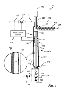
Fig. 1 illustrates a pretreatment arrangement 100 for pretreatment of
lignocellulosic biomass comprising a reactor vessel 101 having an upstream
inlet 102 for
receiving biomass and a downstream outlet 103 for discharging biomass, wherein
the
pretreatment arrangement 100 comprises a gas valve 104 configured to remove
gas from the
reactor vessel 101, measuring means 105 for measuring at least the temperature
and pressure
in the pretreatment reactor, and gas flow control means 106 configured to
adjust the outflow
of gas from the gas valve 104 in response to the measured process parameters.
Lignocellulosic biomass 107 enters the reactor vessel 101 by means of the
inlet 102. In Fig. 1, the biomass 107 is fed into the reactor vessel 101 by
means of a plug
screw feeder 108. The plug screw feeder 108 secures an even flow of biomass
into the reactor
vessel 101. The pretreatment arrangement 100 is not limited to a specific type
of inlet or
feeding means, but any inlet or means for feeding biomass, known to those
skilled in the art,
may be used.
The lignocellulosic biomass may be, but is not limited to, hardwoods,
softwoods, sugarcane bagasse, energy cane, corn stover, corn cobs, corn
fibers, straw from
rice, wheat, rye and other crop or forestry residues.
As illustrated by the arrow 109, steam and/or additional catalysts may in
embodiments be added to the reactor vessel 101 for certain pretreatment
conditions.
During operation, the reactor vessel 101 content can be divided into a gas
phase arranged above the biomass slurry level 110 and a biomass slurry phase,
wherein the
reactions for degrading or partially degrading the lignocellulosic biomass
take place.
During such reactions, and particularly when additional steam 109 or gases are
introduced into the reactor vessel 101, an excess amount of gases are
concentrated in the gas
phase of the reactor vessel 101.
During degradation of the lignocellulosic biomass, chemical bonds are broken
and may result in the liberation of volatile compounds (VOC) and gases. Such
gases are
typically inert gases; i.e. gases that have no or extremely low chemical
reactivity with other
substances. Examples of inert gases include e.g. nitrogen (N2) and carbon
dioxide (CO2). If
sulphur dioxide (SO2) is used to catalyze the pretreatment reaction, SO2 may
also become
concentrated in the gas phase of the reactor vessel 101.
As described above, an unstable pretreatment is less efficient, i.e. provides
a
lower yield, and also leads to problems such as build-up of deposits on the
inner walls of the
CA 03163949 2022- 7-6
WO 2021/156246 8
PCT/EP2021/052421
reactor vessel. The present inventors have realized that problems with
unstable pretreatment
conditions are very much associated with accumulation of gases, primarily
inert gases, in the
reactor vessel and with the increase of temperature and pressure,
respectively, in the reactor
vessel due to the accumulation of gases.
The present invention is based on the recognition that a controlled removal of
gases (mainly comprising inert gases formed during pretreatment), can provide
for a stable
pretreatment. More specifically, controlled gas removal from the reactor
vessel through an
adjustable gas valve and based on measurements of the temperature and pressure
of the
reactor vessel is proposed. The temperature and pressure have been identified
as key
parameters for achieving stable pretreatment conditions. According to
preferred
embodiments, the pretreatment arrangement comprises gas flow control means
configured to
adjust the outflow of gas from the gas valve in response to the relationship
between the
temperature and pressure, e.g. expressed as a ratio between temperature and
pressure, so as to
achieve a controlled flow of gas out from the reactor vessel.
Fig. 2 is a schematic exemplary diagram to illustrate the general relationship
between gas formation and temperature and pressure in a conventional
pretreatment
arrangement without gas removal. As evident from the curve, the gas flow out
from the
reactor vessel is zero. As the gas amount in the reactor vessel increases, the
relationship
between temperature and pressure, here exemplified as a temperature to
pressure ratio,
changes. For illustrative purposes, pressure is kept constant in the
theoretical simulation of
Fig. 2 (e.g. corresponding to a process control mechanism involving a constant
desired
(target) pressure value) and it is evident that the temperature to pressure
ratio is not constant.
The temperature to pressure ratio decreases as inert gases accumulate in the
reactor.
Fig. 3 is a schematic exemplary diagram to illustrate the relationship between
gas flow and temperature and pressure in a pretreatment arrangement with
controlled removal
of gas according to an exemplary embodiment of the present invention. Also in
the
theoretical simulation of Fig. 3, the pressure in the reactor is the same
throughout the process.
The gas flow control means is configured so as to adjust the gas flow in
response to the
temperature and pressure. The control criterion is to keep the ratio between
temperature and
pressure within a predetermined reference ratio interval. When the ratio
determined from
temperature and pressure measurement deviates too much, the outflow of gas
from the gas
valve is changed to counteract the deviation. In Fig. 3, the ratio between
temperature and
pressure first decreases but as the gas flow, due to the gas flow control
means of the
invention, increases, the ratio gradually goes back to its desired value or
interval and a
CA 03163949 2022- 7-6
WO 2021/156246 9
PCT/EP2021/052421
steady-state condition between gas flow and temperature/pressure-ratio is
achieved. Such a
steady-state may prevail until there is another change in the relationship
between pressure
and temperature, for example due to a change in the accumulated gases in the
reactor caused
by altered reaction conditions, process disturbances, variations in the
incoming
lignocellulosic material, etc.
Returning to Fig. 1, some features and embodiments of the pretreatment
arrangement will now be described more in detail.
The measuring means 105 for measuring the temperature and pressure within
the reactor vessel is configured to measure the temperature at a plurality of
points in time,
preferably continuously, within the reactor vessel 101 and to measure the
pressure at a
plurality of points in time, preferably continuously, within the reactor
vessel 101.
The measuring means 105 typically comprises conventional temperature and
pressure sensors, arranged to measure the temperature and pressure,
respectively, within the
reactor vessel 101 and communicate the registered temperature and pressure
signals to the
gas flow control means 106. The temperature and pressure sensors are arranged
in an upper
portion 114 of the reactor vessel, above the biomass slurry level 110.
The gas flow control means 106 is configured to adjust the outflow of gas
from the gas valve 104 in response to the measured temperature, pressure, and,
possibly other
process parameters. The gas flow control means 106 typically comprises
conventional control
means arranged so as communicate with and collect signals from the measuring
means 105,
112 and to send control signals to the gas valve 104, or, alternatively, to an
intermediate
valve adjustment device (not shown), in order to adjust the opening of the gas
valve 104.
The gas flow control means 106 preferably comprises automated control
means, such as computer control means, suitable for online or inline
pretreatment control.
The gas valve 104 is arranged in gas communication with the reaction vessel
101 so as to secure proper removal of gases. More specifically, the gas valve
104 is arranged
in gas communication with the portion of the reaction vessel which, during
operation,
contains the gas phase of the reactor vessel content.
The gas valve 104 may be attached to the reactor vessel 101 or it may be
connected to the reactor vessel 101 by means of a pipe, a tube, or another
connecting means.
The gas valve 104 may also be arranged in the reactor vessel 101 or extend
into the reactor
vessel 101. In Fig. 1, the gas valve 104 is arranged outside of the reactor
vessel 101 and
connected to the reactor vessel by means of e.g. a pipe. The outflow of gas is
illustrated by
the arrow 111.
CA 03163949 2022- 7-6
WO 2021/156246 10
PCT/EP2021/052421
The gas valve 104 has an adjustable opening configuration, i.e. the degree of
opening of the gas valve 104 and/or the time of opening of the gas valve 104
is adjustable.
The gas valve 104 may be operable between an open and closed configuration in
a "1/0",
stepwise, or stepless manner.
In some embodiments, the gas valve 104 is configured to be operable between
an open and a closed position. A flexible, yet controlled system is thereby
achieved which
allows for quick adjustments or "corrections" of reaction conditions within
the reactor vessel
101. It also allows for energy savings, since the gas valve 104 may be kept in
a closed
position when there is no need for gas removal from the reactor vessel 101.
In alternative embodiments, the gas valve 104 is configured to remove gas
continuously from the reactor vessel 101. This may be beneficial for certain
pretreatment
processes, such as steam explosion, where there is also an inflow of
additional steam and,
potentially gas catalysts, which can disrupt the balance within the reactor
vessel 101. A
small, continuous outflow of gas may then compensate for these fluctuations
and re-establish
the constant and stable pretreatment conditions within the reactor vessel.
Thus, it may be
beneficial for the gas flow control means 106 to set a minimum outflow of gas,
which the
system is not to go below.
The skilled person understands that the gas flow rate may depend for example
on reactor size, raw material, pressure.
The present disclosure is not limited to a specific type of valve, and, as
evident
to the skilled person, the type of valve used may depend for example on the
process
conditions and method for pretreatment and whether the reactor is used for
large-scale or
small-scale pretreatment processes. In particular, the size and shape of the
reactor vessel may
affect which type of valve is suitable.
Exemplary valves include solenoid valve, needle valve, pinch valve, ball
valve, globe valve, knife valve, spool valve, butterfly valve, choke valve,
diaphragm valve,
membrane valve, gate valve, piston valve, and plug valve.
In preferred embodiments, the gas valve 104 is a control valve, i.e. a valve
with variable and controllable degree of opening The control valve is
configured with an
adjustable, stepwise or stepless, opening for the gas outflow, not just a 1/0
or on/off ("1/0")
mode. In embodiments, the control valve is a globe valve, a ball valve, or a
needle valve.
In embodiments with relatively small reactors and low flow rates, the gas
valve 104 could for example be a needle valve. A needle valve typically
comprises a small
CA 03163949 2022- 7-6
WO 2021/156246 11
PCT/EP2021/052421
port and a threaded, needle-shaped plunger and allows for precise control of
the gas outflow
where a relatively low flow rate is desired.
In embodiments, the pretreatment arrangement further comprises an optional
flow meter 112 configured to measure the outflow of gas from the reactor
vessel 101. The
gas flow control means 106 is then configured to adjust the opening of the gas
valve 104, i.e.
to increase or decrease the outflow of gas from the reactor vessel 101, also
in response to the
measured outflow of gas.
For example, if the flow meter 112 indicates that there is an improper flow of
gas (either too much or too low), the gas valve 104 may be opened or closed in
response to
such indications. This may be beneficial to secure that energy is not lost or
"wasted" during
the reaction. A cost-efficient and precisely controlled approach is thereby
achieved.
If the outflow of gas from the reactor vessel 101 is too high, the pressure
within the reactor may drop too fast, which in turn can lead to excessive
boiling of the slurry.
It may therefore be advantageous to have a relatively low outflow of gas.
A possible approach for the gas flow control means 106 would be to control
the removal of gases such that a desired ratio between temperature and
pressure, as well as a
desired interval for the actual flow of gas, detected by the flow meter 112,
is achieved or
targeted. This may be beneficial to secure stable reaction conditions,
efficient pretreatment
performance and energy-efficient pretreatment. A cost-efficient and adequately
controlled
pretreatment process can thereby be achieved.
The gas valve 104 and the flow meter 112 may be arranged within the same
unit or may be connected by means of a pipe or tube. In the example of Fig. 1,
the gas valve
104 and the flow meter 112 are arranged separately, but in gas communication.
The flow
meter 112 may be arranged upstream or downstream of the gas valve 104. In the
example of
Fig. 1, the flow meter 112 is arranged downstream of the gas valve 104 and
adapted to
measure the outflow of gas from the gas valve 104.
The pretreatment arrangement 100 is not limited to the use of a specific flow
meter 112, but any type of flow meter suitable for measuring the outflow of
gas from the
reactor vessel 101 may be used.
The flow meter 112 may e.g. be selected from a differential pressure flow
meter, a variable flow meter, a Coriolis flow meter, an ultrasonic flow meter,
an optical flow
meter or a thermal dispersion flow meter.
In embodiments, the flow meter 112 is a rotameter. The rotameter is a type of
variable flow meter that measures the volumetric flow rate of the gas. A
rotameter typically
CA 03163949 2022- 7-6
WO 2021/156246 12
PCT/EP2021/052421
comprises a tapered tube with a "float-; i.e. at weight that is pushed upwards
when the gas
flow increases. The flow rate is measured by allowing the cross-sectional area
that the gas
travels through to vary.
The reactor vessel 101 in Fig. 1 is a vertical reactor vessel. However, the
pretreatment arrangement of the present disclosure is not limited to the use
of a vertical
reactor vessel. Horizontal, as well as inclined, reactor vessels are also
conceivable for the
purpose of the present disclosure.
As illustrated in Fig. 1, the reactor vessel 101 is a vertical reactor vessel
extending along a longitudinal center line 113 and comprising an upper portion
114, and a
lower portion 115; the gas valve 104 or the pipe being arranged in the upper
portion 114 of
the reactor vessel 101.
The biomass 107 fed into the vertical reactor vessel 101 flows from the inlet
102 to the outlet 103 by means of gravity, and no additional means to increase
the flow of
biomass within the reactor vessel 101 is required. The gases formed in the
reactor vessel 101
during the pretreatment reactions assemble in the upper portion 114 of the
reactor vessel 101,
i.e. above the biomass slurry level. The gas valve 104 or pipe for removing
gases is therefore
arranged in the upper portion 114 of the reactor vessel 101 to secure
efficient removal of gas
(not slurry) from the reactor vessel 101.
As mentioned, the upper portion 114 of the reactor vessel 101 corresponds to
the portion of the reactor vessel 101 arranged above the biomass slurry level
110 within the
reactor vessel 101 during operation. The lower portion 115 of the reactor
vessel 101
corresponds to the portion(s) of the reactor vessel 101 arranged below the
biomass slurry
level 110 within the reactor vessel 101 during operation. The interface
between the upper 114
and the lower portion 115 may correspond to the maximum biomass slurry level
during
operation.
In embodiments, the upper portion 114 has a longitudinal extension
corresponding to 10-50 % of the maximum longitudinal extension of the reactor
vessel 101
and the lower portion 115 has a longitudinal extension corresponding to 50-90
% of the
maximum longitudinal extension of the reactor vessel 101.
As illustrated in Fig. 1, the lower portion 115 advantageously tapers towards
the outlet 103 of the reactor vessel 101. More specifically, the lower portion
115 is at least
partly tapering towards the outlet. Preferably, at least a bottom portion 116
of the lower
portion 115, i.e. the portion 116 in the vicinity of the outlet 103, is
tapering. This is to
facilitate and improve discharge of biomass 117 from the outlet 103.
CA 03163949 2022- 7-6
WO 2021/156246 13
PCT/EP2021/052421
Typically, the reactor vessel 101 has a circular or oval cross-section. The
reactor vessel 101 may e.g. be cylindrical. In preferred embodiments, the
reactor vessel 101
has a rotational symmetry with respect to the longitudinal center line 113.
The pretreatment arrangement of the present disclosure may be used for
various types of pretreatment methods including both hydrothermal, chemical,
physical and
biological methods.
In embodiments, the pretreatment involves steam explosion. In other words,
the pretreatment arrangement 100 comprises a steam explosion arrangement.
During steam explosion, an excess amount of gas may assemble in the reactor
vessel, and the problems caused by these gases are particularly severe.
Therefore, controlled
gas removal in accordance in the present invention is suitable for steam
explosion
arrangements.
In embodiments, the pretreatment arrangement 100 comprises a sluice vessel
118 arranged downstream of and in fluid communication with the reactor vessel
101, wherein
the sluice vessel 118 is configured to discharge biomass received from the
outlet 103 of the
reactor vessel 101. A sluice vessel 118 is advantageous for controlling the
discharge of the
pretreated lignocellulosic material 117 and for improving the control of the
process
conditions within the reactor vessel 101.
The sluice vessel 118 may comprise a first discharge valve 119, a second
discharge valve 120 arranged downstream of the first discharge valve 119 and a
compartment
121 arranged between the first 119 and the second 120 discharge valves. The
sluice vessel
118 may further comprise means 122 for increasing the pressure in the
compartment 121 of
the sluice vessel 118. The means 122 for increasing the pressure may be a tube
adapted to
supply gas, e.g. steam to the compartment 121, and may e.g. comprise a valve
123 to control
the supply of gas. The first 119 and the second 120 discharge valve are
configured to be
operable between an open and a closed position. Both discharge valves (119 and
120) are in a
closed position when the pressure is increased in the compartment 121.
The provision of a sluice vessel 118 downstream of the reactor vessel 101
allows the pressure to be remained within the reactor vessel 101, while the
pressure may be
significantly increased and decreased in the sluice vessel 118. A pressure
drop resulting from
the discharge of biomass from the second discharge valve 120 of the sluice
vessel 118
improves the division of the pretreated biomass 117 into smaller particles.
The sluice vessel
118 may therefore be adapted for steam explosion. Performing the steam
explosion outside of
and downstream of the reactor vessel 101 is beneficial in that potential
deposits resulting
CA 03163949 2022- 7-6
WO 2021/156246 14
PCT/EP2021/052421
from harsh pretreatment conditions (high pressures and high temperatures) are
prevented
within the reactor vessel 101. By increasing the pressure inside the sluice
vessel 118, a higher
pressure drop is obtained when the biomass is discharged from the second
discharge valve
120. As a result, the treated biomass will be divided into smaller pieces
compared to if a
direct discharge from the reactor vessel 101 is performed.
As illustrated in Fig. 1, the pretreatment arrangement may comprise a scraping
device 124. The scraping device 124 secures a continuous flow of biomass in
the reactor
vessel 101, while scraping deposits formed on the interior walls 125 of the
reactor vessel 101.
The scraping device 124 prevents build-up of deposits inside the reactor
vessel 101, and the
full interior volume of the reactor vessel 101 can therefore be utilized for
the pretreatment of
lignocellulosic biomass.
The scraping device 124 comprises a shaft 126 and at least two scraping blades
127 extending from the shaft 126. The scraping blades 127 are preferably
configured to
follow the contour, without contacting the interior walls 125, of at least a
portion of the lower
portion 115 of the reactor vessel 101. The shaft 126 may be arranged outside
of the reactor
vessel 101 or may be configured to extend into the upper portion 114 of the
reactor vessel
101. Preferably, the shaft 126 does not extend into the lower portion 115 of
the reactor vessel
101. In other words, the shaft 126 does not extend into a portion of the
vessel where biomass
slurry is present. The reason is that a shaft 126 extending into the biomass
slurry may form an
additional surface onto which deposit may form and develop.
The scraping blades 127 are arranged to rotate about the longitudinal center
line 113, and are preferably arranged to provide an efficient scraping of the
interior reactor
walls 125 without risking that these become damaged by the blades. Therefore,
a small gap
should be provided between the scraping blades 127 and the interior walls 125.
In embodiments, the scraping blades 127 are arranged at a distance, dl, from
the interior walls 125 of the reactor vessel 101, wherein the distance, dl,
corresponds to from
0.5 to 20 %, preferably from 2 to 15 % of the diameter of the reactor vessel
101.
According to another aspect of the present disclosure, a method for
controlling
the outflow of gas in a pretreatment arrangement is proposed. Fig. 4
schematically illustrates
the steps of a method for controlled pretreatment to an exemplary embodiment
of the present
invention. In step Si, a lignocellulosic biomass material is pretreated in a
pretreatment
arrangement comprising a reactor vessel and an adjustable gas valve arranged
to remove gas
from the reactor vessel. In step S2, a number of process parameters of the
pretreatment in the
reactor vessel are measured. The measured process parameters include at least
a temperature
CA 03163949 2022- 7-6
WO 2021/156246 15
PCT/EP2021/052421
parameter and a pressure parameter, based on which a ratio is determined in
step S3. In step
S4, the outflow of gas from the gas valve is adjusted in response to the
determined ratio.
The temperature is preferably measured at a plurality of points in time,
preferably continuously, within the reactor vessel. The pressure is preferably
measured at a
plurality of points in time, preferably continuously, within the reactor
vessel.
The method is preferably automated and adapted for continuous operation. In
embodiments, step S2 of measuring comprises monitoring the process parameters
in a
continuous or semi-continuous manner and the step of adjusting comprises
automatically
adjusting the gas valve opening in response to the monitored process
parameters.
The adjustment in step S4 may comprise comparing the determined ratio to a
predetermined reference ratio for the pretreatment and adjusting the outflow
of gas from the
gas valve if the determined ratio deviates from the predetermined reference
ratio, such as by
more than 5%, such as by more than 10%.
In embodiments, the reference ratio, Qrefi represents the desired ratio
between
the pressure and temperature for the pretreatment in the reactor vessel, i.e.
Qref = temp/P ratio
or Qref = P/temp (where temp is the measured temperature or a parameter
including or
directly dependent on the measured temperature and P is the measured pressure
or a
parameter including or directly dependent on the measured pressure). Qref may
be a
predetermined set value or interval, or, alternatively, be predetermined to be
for example the
ratio between the pressure and temperature at an initial stage of the
pretreatment process.
In practice, the adjustment step will typically involve to increase the
removal
of gases (typically inert gases), i.e. increase the opening of the gas valve,
when the pressure is
too high, or, in other words, when the pressure due to gas accumulation has
increased more
than the temperature increase (non-linear relative to the temperature).
In embodiments, the process parameters measured in step S2 further include a
gas parameter indicating the amount or concentration of gas, typically inert
gases, in the
reactor vessel.
Accordingly, a more sophisticated and controlled removal of gases from the
reactor vessel, and thus also a more controlled pretreatment, can be achieved.
In embodiments, the method comprises measuring the outflow of gas,
typically inert gases, from the reactor vessel and adjusting the opening of
the gas valve in
response also to the measured outflow of gas.
CA 03163949 2022- 7-6
WO 2021/156246 16
PCT/EP2021/052421
In embodiments, the method comprises setting a lower limit for the outflow of
gas from the gas valve, so as to enable a continuous outflow of gas from the
gas valve during
the pretreatment.
The pretreatment control of the present invention is particularly well suited
for
steam explosion processes, which are typically associated with harsh reaction
conditions and
a lot of accumulated gases. Therefore, the method may with advantage include a
steam
explosion step.
The temperature in the reactor vessel during pretreatment with gas flow
control in accordance with the present invention, may for example be in the
interval of 185 to
225 C, such as 200 to 215 C.
The pressure in the reactor vessel during pretreatment with gas flow control
in
accordance with the present invention, may for example be in the interval of
10 to 25 bar,
such as 15 to 20 bar.
With reference to Fig. 5, the present disclosure further provides a system 500
for treatment of lignocellulosic biomass comprising a pretreatment arrangement
501 for
pretreatment of lignocellulosic biomass according to the first aspect of the
present disclosure,
a hydrolysis unit 502 arranged downstream of and in fluid communication with
the
pretreatment arrangement 501, and optionally, a fermentation unit 503, such as
a
fermentation vessel, arranged downstream of and in fluid communication with
the hydrolysis
unit 502. The system 500 may comprise additional units and components known to
those
skilled in the art. For example, a separation unit may be arranged between the
pretreatment
arrangement 501 and the hydrolysis unit 502, and/or between the hydrolysis
unit 502 and the
fermentation unit 503.
In the hydrolysis unit, the pretreated biomass is subject to enzymatic
hydrolysis
by means of saccharification enzymes. Fermentation of the hydrolysate into a
target chemical
is typically performed by means of fermenting organisms, such as bacteria
and/or yeast. The
system 500 may also comprise a product recovery unit, such as distillation or
ion exchange
chromatography, arranged downstream of and in fluid communication with the
fermentation
unit 503.
Terms, definitions and embodiments of the first aspect of the present
disclosure apply mutatis mutandis to the other aspects of the present
disclosure, and vice
versa.
CA 03163949 2022- 7-6
WO 2021/156246 17
PCT/EP2021/052421
Even though the present disclosure has been described with reference to
specific exemplifying embodiments thereof, many different alterations,
modifications and the
like will become apparent for those skilled in the art.
Variations to the disclosed embodiments can be understood and effected by
the skilled addressee in practicing the present disclosure, from a study of
the drawings, the
disclosure, and the appended claims. Furthermore, in the claims, the word
"comprising" does
not exclude other elements or steps, and the indefinite article "a" or "an"
does not exclude a
plurality.
CA 03163949 2022- 7-6