Note: Descriptions are shown in the official language in which they were submitted.
WO 2021/142273
PCT/US2021/012716
WELD WIRE GUIDE CONDUIT
CROSS-REFERENCE TO RELATED APPLICATIONS
[0001] The present application is a PCT International Application,
which claims the
benefit of United States Provisional Patent Application No. 62;959,330, filed
January
10, 2020.
FIELD OF THE INVENTION
[0002] The present disclosure relates to a conduit especially
adapted for use in a
weld wire dispensing system or as a control cable conduit. In particular, the
present
disclosure relates to a spring type wire guide conduit constructed of coiled
wire having
an oval or elliptical cross-section and further featuring locally hardened
surface areas
on the inside of the conduit to improve wire flow through the conduit
BACKGROUND
[0003] Metal Inert Gas (MIG) welding also referred to as "wire-
feed" or Gas Metal
Arc Welding (GMAW) utilizes heat from an electrical arc to melt a consumable
electrode to form a weld on a workpiece. In this description, these systems
will be
collectively described as MIG welding systems. A MIG welding system typically
includes a power supply: a gas supply and an electrode supply connected to a
welding
device or welding gun. A ground cable is used to connect the workpiece to the
power
supply. The welding device generally includes a handle, a gooseneck and an end
assembly. The welding system can be automatic or semi-automatic and may be
manually or robotically controlled. The electrode and gas are coupled through
a
conduit in the handle and the gooseneck to the end assembly of the welding
device.
The electrode extends through the contact tip of the end assembly and the gas
moves
around the contact tip in the nozzle of the end assembly to shield the weld
site. When
1
CA 03164144 2022- 7- 7
WO 2021/142273
PCT/US2021/012716
the welding device is activated, the electrode is fed through the contact tip
toward the
workpiece and the gas is directed through the nozzle to flood the weld site.
When the
electrode is placed adjacent to or in contact with the workplace, the
electrode
completes an electrical circuit between the power supply and the workpiece,
allowing
current to flow through the electrode to the workpiece. The current produces
an arc
between the electrode and the workpiece. The heat of the arc melts the
electrode and
the workpiece in the region surrounding the arc, creating a weld puddle. The
gas
flowing out the nozzle shields the weld puddle from atmospheric gases and
outside
contaminants. The type of shielding gas used in MIG welding varies depending
on
many factors, Noble or inert gases such as Argon are often used, However,
Carbon
Dioxide (CO2) and a mixture of gases such as CO2 and Argon are also used. Once
the
electrode is moved away from the workpiece, the electric circuit is broken and
the weld
puddle cools and solidifies, forming a weld,
[00043 In typical MIG welding systems, a flexible wire guide
conduit is used to
transport the flexible electrode wire from a storage bin, typically from a
wire spool,
through a wire feeder dnve device and through the flexible wire guide conduit
to the
torch. Flexible conduits are generally formed by coiling a wire to produce a
hollow
passageway through which the electrode wire moves These types of conduits are
often referred to as spring type or spring liner conduits.
[00051 In the past, weld wire conduits used in weld wire
dispensing systems have
been constructed using wire having a rectangular cross-section. However, in
instances where the weld torch cable or weld wire conduit is bent or flexed,
the edges
of the wire forming the conduit are exposed. The exposed edges of the wire
forming
the conduit damages the surface of the weld wire as the weld wire is pushed or
pulled
through the conduit. The sharp edges of the conduit wire can "shave" or cut
the weld
2
CA 03164144 2022- 7- 7
WO 2021/142273
PCT/US2021/012716
wire as the weld wire is moved through the passageway of the conduit. The
sharp
edges also increase friction between the weld wire and the conduit as the weld
wire is
moved through the weld wire conduit.
[0006] The higher friction results in more force being required to
move the weld
wire through the conduit, which decreases the overall efficiency of the weld
wire
dispensing system, and can lead to binding and failure of the weld wire
delivery
system. Damage to the surface of the weld wire caused by the exposed edges of
the
wire forming the conduit also results in the shavings and residue collecting
in the inner
passageway of the conduit. In some instances, the build-up of shavings and
residue
eventually prevents the weld wire from being pulled or pushed through the
conduit. In
addition, as the shavings and residue build-up in the conduit, they
significantly
increase friction between the weld wire and the conduit and thus increase the
force
needed to push or pull the weld wire through the conduit. The increase in
friction also
causes drive roll wire slippage in the weld wire dispensing system, as well as
burn-
back in the system. The shavings and residue can also lead to the weld wire
being
stuck inside the torch contact tip.
[0007] Wire guide conduit conduits are also constructed of wire
having a circular
cross-section, However, it is difficult to provide a protective coating on
only the inner
surface of the conduit constructed of round wire. Round wire tends to rotate
in dies;
therefore, it is extremely difficult to set a desired surface of the round
wire in a
continuous position as necessary to provide coating on only the inner surface
of the
conduit which contacts the electrode wire.
[0008] The present applicant has devised improvements in the area
of flexible wire
conduits and have introduced the use of elliptical or non-round wire to form
weld wire
conduits. Wire guide conduit conduits based on such wire shapes have resulted
in
3
CA 03164144 2022- 7- 7
Attorney Docket No. 91694-113
significant improvements in the performance of wire guide conduit conduits for
welding. Such configurations are described and claimed in Applicant's
previously
issued United States Patent Number 9,056,367 and United States Patent Number
9,687,932.
[0009] In an effort to improve weld wire guide conduit performance, it is
known to
provide surface coatings such as lubricants to the wire forming the wire guide
conduit.
An example is a coating of tungsten sulfide. Although such treatments are
beneficial,
they tend to have a limited operational lifespan as the lubricant materials
dissipate
over operational use of the wire guide conduit.
[0010] Despite the numerous improvements in the art, there remains a
continued
need to reduce friction of electrode wire fed to the wire guide conduit and
increase
their service life. In order to form the tightly wound wire guide conduit
conduits,
relatively soft metals are used such as 1040 carbon steel. A disadvantage of
the
formability requirement is the relative softness of such metal alloys.
Softness leads to
wear over time as the electrode wire is fed through the wire guide conduit,
especially
where relatively tight bends are present. Wear on the inside surfaces of the
wire
forming the wire guide conduit leads to shaving of electrode wire as mentioned
previously, and even complete cutting through of the wire guide conduit.
Further, such
wear tends to increase friction forces acting on the electrode wire as it
moves to the
wire guide conduit and causes an enlargement of the internal passageway of the
wire
guide conduit which can lead to buckling of the electrode wire; again
resulting in
decreased efficiency of electrode wire transfer.
[0011] The above referenced design challenges related to the transfer of
MIG
welding electrode wire are also encountered in the field of control wires used
for many
industrial and commercial applications. For example, control cables are widely
used
4
Date Recue/Date Recieved 2024-02-05
WO 2021/142273
PCT/US2021/012716
for bicycles for brake and derailleur gear selection control, motorcycles and
motor
vehicles as clutch and transmission cables, and in other automotive
applications for
controlling movable panels such as HVAC control doors, etc. Coiled spring type
control
cables are further used in additional widespread applications.
[0012] In view of the foregoing there remains a need for a wire
guide conduit having
longer life capabilities and improved performance especially as related to
friction and
service life associated with the transfer of a wire electrode or control
cable.
BRIEF SUMMARY OF THE INVENTION
[0013] In accordance with the present invention a wire guide
conduit is provided
constructed from a coiled wire having an oval or elliptical cross-section.
Before the
wire is formed into the coil, a surface heat treatment process is performed to
create
locally hardened regions along the wire of the wire guide conduit Such locally
hardened regions can be provided by, for example, laser treatment or other
directed
energy processes which cause local heating of the surface of the wire to
create such
hardened regions. These hardened regions are intentionally created to be at
discrete
isolated locations as to not interfere with the formability of the wire which
is adversely
affected by increasing hardness.
[0014] In the manufacturing process for forming the wire guide
conduit the oval wire
is treated by a laser (or other directed energy process) to create dots or
stripes of
locally hardened regions and the wire is thereafter rolled into a wire guide
conduit with
the locally hardened regions facing the inside surface of the conduit. As the
electrode
wire moves through such =a wire guide conduit, the locally hardened areas act
essentially as wear bars or hard points of contact for supporting the
electrode wire as
it moves through the conduit. Wear of the conduit wire is reduced in these
locally
hardened regions. This leads to improved longevity and reduced friction during
use.
CA 03164144 2022- 7- 7
WO 2021/142273
PCT/US2021/012716
Surface coatings and lubricants such as mentioned previously may also be used
in
conjunction with the present invention. The wire guide conduit in accordance
with this
invention may also be used as a control cable conduit to allow an actuation
cable to
be connected between two points_
[0015] According to an aspect, a wire guide conduit adapted for
allowing movement
of a core is provided_ The conduit includes a wire coiled in a helical manner
to define
the conduit and 'form an internal passageway of the conduit, the passageway
defining
a longitudinal axis, wherein the wire has a cross-section with a major axis
and a minor
axis, wherein a thickness of the wire along the major axis is greater than a
thickness
of the wire along the minor axis, wherein the wire is coiled in the helical
manner to
present the major axis generally parallel with the longitudinal axis of the
passageway,
the passageway adapted for receiving the core, wherein the wire has a straight
configuration prior to being coiled and includes periodically spaced locally
hardened
regions having a surface hardness greater than areas of the wire outside of
the locally
hardened regions, wherein the locally hardened regions are disposed on an
inside
surface of the conduit facing the internal passageway when the wire is coiled
in the
helical manner,
[0016] In one aspect, the wire consists of a single wire coiled in
the helical manner.
[0017] In one aspect, the wire has a generally elliptical cross-
section.
[0018] In one aspect, the internal passageway of the wire guide
conduit defines an
inner diameter, and wherein the inner diameter is constant along substantially
the
entire length of the conduit
[0019] In one aspect, the internal passageway of the wire guide
conduit defines an
inner diameter, and wherein the inner diameter is adapted to closely receive
the core
in the form of a wire having a circular cross-sectional shape.
6
CA 03164144 2022- 7- 7
WO 2021/142273
PCT/US2021/012716
[0020] In one aspect, the wire has opposed first and second sides
on opposite
sides of the major axis and extending along the major axis and wherein the
locally
hardened surfaces are provided on only the first side of the wire so that when
the wire
is coiled to form the wire guide conduit, the first side of the wire forms the
inner
passageway of the conduit so that the hardened surfaces are provided only on
the
inner passageway of the conduit.
[0021] In one aspect, the wire guide conduit is configured to be
used in a weld wire
dispensing system with the core in the form of a welding electrode wire.
[0022] In one aspect, the locally hardened regions form a pattern
along the wire
when the wire is in the straight configuration.
[0023] In one aspect, locally hardened regions are equally spaced
when the wire
is in the straight configuration.
[0024] In one aspect, the pattern includes one of a series of
dots, a series of stripes,
a series of alternafingly inclined stripes, a series of inter-locking circles
along the
length of the wire, or a series of interlocking circles forming stripes across
the surface
of the wire.
[0025] In one aspect, the locally hardened region is disposed
within a profile of the
wire when the wire is in a straight configuration such that the locally
hardened region
does not substantially project relative to adjacent non-hardened. regions.
[0026] In one aspect, an outside surface of the wire guide conduit
does not include
any locally hardened regions.
[0027] In one aspect, the locally hardened regions are disposed at
various
circumferential and longitudinal locations on the inside surface of the
conduit.
[0028] In one aspect, the locally hardened regions do not extend
fully across the
wire along the major axis.
7
CA 03164144 2022- 7- 7
WO 2021/142273
PCT/US2021/012716
[0029] According to another aspect, a method for forming a wire
guide conduit
forming an internal passageway for the passage of a core. The method includes
providing a wire in a straight configuration, the wire having a cross-section
forming a
major axis and a minor axis, wherein a thickness of the wire along the major
axis is
greater than a thickness of the wire along the minor axis; wherein the wire
has opposed
first and second sides on opposite sides of the major axis and extending along
the
major axis and applying an energy beam to the first side of the wire causing
localized
heating of a surface of the first side and creating discrete and separated
areas of
locally hardened regions, and coiling the wire having the locally hardened
regions such
that the major axis of the wire is aligned with a longitudinal axis defined by
the conduit
in a manner to present the locally hardened regions toward the internal
passageway
to form the wire guide conduit
[0030] In one aspect, the core is an electrode wire and the wire
guide conduit is
used for conducting the electrode wire toward a KG welding torch.
[0031] In one aspect, the energy beam is a laser producing a beam
directed onto
the first surface of wire.
[0032] In one aspect, the beam is tightly focused and moves
longitudinally relative
to the wire during application of the beam, wherein the beam is a continuous
wave or
pulsed_
[0033] In one aspect, as the beam moves longitudinally relative to
the wire, the
beam is maintained at a constant lateral orientation relative to the cross-
section axis
of the wire during application of the beam or the beam moves laterally
relative to the
wire during application of the beam,
8
CA 03164144 2022- 7- 7
WO 2021/142273
PCT/US2021/012716
[0034] In one aspect, the locally hardened regions are disposed at
various
circumferential and longitudinal locations on the inside surface of the
conduit and no
locally hardened regions are disposed on the outside surface of the conduit.
[0035] Additional substance and advantages of the present disclosure will
become
increasingly apparent by reference to the following drawings and the
description.
BRIEF DESCRIPTION OF THE DRAWINGS
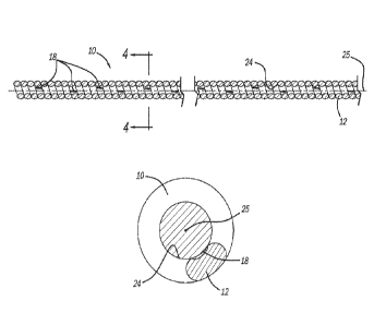
[0036] Figure 1 is a side cutaway view of a spring type wire guide
conduit.
positioned in a welding torch.
[0037] Figure 2 is a side elevational view of a wire guide
conduit: showing a
protruding electrode wire.
[0038] Figure 3 is a cross-sectional view of a wire guide conduit
according to the
present disclosure.
[0039] Figure 4 is an end view of the conduit showing the inner
passageway of the
wire guide conduit.
[0040] Figure 5 is a cross-sectional view of the wire used for
forming the wire guide
conduit.
[0041] Figure 6 is an elevationsl view of wire for forming the
wire guide conduit
showing locally hardened regions along a surface of the wire.
[0042] Figure 7 is a diagrammatic illustration of a laser surface
treatment system.
[0043] Figures 8-11 show alternate embodiments of patterns of
locally hardened
regions of wire for forming a wire guide conduit,
[0044] Figure 12 is a side elevational view of a wire guide
conduit according to the
present disclosure used as a control cable.
9
CA 03164144 2022- 7- 7
WO 2021/142273
PCT/US2021/012716
DETAILED DESCRIPTION OF THE INVENTION
[0045] Referring to Figure 1, a representative welding torch 20 is
illustrated for use
in a MIG welding process. Welding torch 20 includes flexible wire guide
conduit 10
formed of a coiled wire 12. In the MIG welding process, electrode wire 16 is
fed through
wire guide conduit 10 to protrude from torch tip 22. Electrode wire 16 can
also be
generally characterized as al core.
[0046] Wire 12 for forming wire guide conduit 10 has, for example,
an essentially
oval or elliptical cross-sectional shape (which may also be referred to as non-
round).
In this description, such cross-sectional shapes for wire 12 will be referred
to
collectively as having an oval or non-round cross-sectional shape. While the
description of non-round may be used, it will be appreciated that the wire 12
may still
have a rounded shape with rounded edges (for example excluding sharp edges
such
as those arising from a rectangular or square cross-section), and that non-
round can
refer to non-symmetrical shapes as well as symmetrical shapes. Accordingly,
reference to non-round may also be used to signify a cross-section that is
generally
non-circular.
[0047] For example, as shown by Figure 5, wire 12 of a
representative shape in
cross-section forms a major axis A-A and a minor axis B-B. It is understood
that wire
12 does not have a circular cross-sectional shape and that the width of wire
12 along
major axis A-A is greater than the width of the wire along minor axis B-B. In
general,
the cross-sectional shape of the wire 12 is such that the wire 12 does not
have any
sharp corners or flat edges. Wire 12 used to form the conduit 10 can be
constructed
of any material well known in the art which is used to construct conduits. For
example,
the wire 12 may be constructed of 1040 carbon steel and formed by drawing a
source
material through a forming die or roller forming tools. The non-round cross-
section of
CA 03164144 2022- 7- 7
WO 2021/142273
PCT/US2021/012716
the wire 12 permits the wire 12 to be wound or coiled in a controlled manner
to define
the conduit 10.
[0048] When wire 12 is coiled to form wire guide conduit 10, the
wire is oriented
such that major axis A-A is aligned along the longitudinal axis 25 of central
passageway 24 of the wire guide conduit, as shown in Figure 3. Figure 4 is an
end
view of wire guide conduit 10 showing in section a view of oval wire 12, As
shown in
Figure 4, the longitudinal axis 25 appears as a dot: and a cross-section of
the wire 12
is shown. The orientation of the cross-section of Figure 5 is similar to that
of Figure 3,
such that axis B-B is generally aligned transverse to the passageway of the
conduit
when the wire 12 is coned.
(00491 As shown in Figure 5, the non-circular or non-round wire 12
with the major
and minor axis also has a width along axis A-A that is greater than a height
along axis
B-B. Thus, upper and lower surfaces of the wire 12 in Figure 5 are generally
longer
than the side surfaces.
[0050] One advantage of using non-round wire 12 is that it can be
readily oriented
during the coiling operation to present a desired surface of the wire facing
toward
central passageway 24, a feature which is exploited in accordance with the
present
invention. For example, the upper surface of the wire 12 from Figure 5 can be
controlled to be the inner surface when the wire 12 is coiled into the conduit
10. Thus,
the lower surface of the wire 12 in Figure 5 can be controlled to be the outer
surface
of the conduit 10 when the wire 12 is coiled. A round wire, without a major
and minor
axis, cannot be controlled in the same way, and therefore it can be difficult
to ensure
that treatment applied prior to coiling the wire 12 ends up in the desired
location (inside
or outside the coil, depending on the treatment).
11
CA 03164144 2022- 7- 7
WO 2021/142273
PCT/US2021/012716
[0051] There is a broad range of specifications for wire 12 and
wire guide conduit
10. In a representative specification, wire 12 has a major axis A-A dimension
ranging
from approximately 0.050-0.110 inch, and a height along minor axis B-B ranging
from
approximately 0_033-.072 inch. Wire 12 can be formed into wire guide conduit
10
having a number of turns equaling approximately 9-20 windings per inch,
depending
on the wire cross-sectional dimensions,
[0052] Once coiled and formed into wire guide conduit 10, a
representative
configuration has an outer diameter of approximately 0.18 inches and an inner
diameter for passageway 24 of approximately 0.08 inches, depending on the
desired
application and configuration of electrode wire 16, Of course, the thickness
along axis
B-B of the wire 12 will affect the difference between the inner diameter of
the conduit
and the outer diameter of the conduit 10 when the wire 12 is coiled such that
axis
B-B is transverse to the longitudinal direction of the conduit 10. Various
types of
electrode wire 16 can be used with and fed through the wire guide conduit 10
of the
present invention including various steel, aluminum and other alloys having a
wide
range of cross-sectional diameters. Electrode wire 16 can also be of a cored
or solid
type. The electrode wire 16 has an outer diameter that is less than the inner
diameter
of the conduit 10. The size of the conduit 10 may be selected based on the
electrode
wire 16 to be used, or vice versa.
[0053] In accordance with the present disclosure, wire 12, after
being formed to the
desired cross-sectional shape and before being coiled to form wire guide
conduit 10,
is subjected to a local surface heating and hardening operation. The surface
hardening
operation creates localized regions of increased hardness, designated in the
figures
as regions 18_ The regions 18 may be permanently defined on the wire 12 in a
variety
of shapes and/or patterns in a controlled manner, such that the regions 18 may
be
12
CA 03164144 2022- 7- 7
WO 2021/142273
PCT/US2021/012716
located specifically within the passageway of the conduit 10 after winding,
based on
the controlled coiling afforded by the non-round cross-section of the wire 12.
[0054] Referring to Figure 6, in one embodiment wire 12 is shown,
not yet coiled,
as having numerous stripes of hardened areas designated by reference number
188.
Other patterns of forming regions 18 can be provided which are described in
more
detail in the following discussion As shown in Figure 6, the stripe-shapes are
arranged
generally parallel to each other and are spaced apart approximately the same
distance,
[0055] In a representative process, hardened areas 18 may be
formed by
subjecting wire 12 to laser radiation. A representative laser treatment system
26 is
diagrammatically illustrated in Figure 7. As shown, laser source 28 directs of
beam 30
of radiation energy toward wire 12 shown in this figure as being supported by
fixture
32. Laser energy from source 28 causes local heating of the surface of wire
12. While
numerous lasers may be suitable for this application, a fiber laser outputting
radiation
at 1,060 nanometers is suitable in some applications. Alternatively, a CO2 gas
laser
could be used having an output in the 10,600 nm range. Beam 30 forms a focal
spot
diameter of, for example 0,05 rim. Such local heating and the subsequent
quenching
of the heated area causes surface hardening in a well-known manner. For
example,
in representative configurations, wire 12 formed of high carbon steel tempered
to a
hardness of 45-47 Rockwell C can be locally hardened in regions 18 to a level
of about
58 Rockwell C. The surface hardening is desirably to a limited depth as shown
in the
cross-sectional view of Figure 5. In one representative configuration, the
hardness
depth is about 0,25 nm. By forming hardened regions 18 at local areas with a
limited
depth, their presence does not adversely impact the formability of wire 12;
allowing
the wire to be coiled to form wire guide conduit 10,
13
CA 03164144 2022- 7- 7
WO 2021/142273
PCT/US2021/012716
po56] Various types of lasers and processes can be used to produce regions 18.
For example, wire 12 can be drawn through fixture 32 in a continuous manner
with a
pulsed laser directed to a surface of the wire producing a series of "dot"
shaped regions
18A such as illustrated by Figure 8. In this approach, the feed rate of the
wire 12
through the fixture may be held constant, with the pulse rate also held
constant to
create evenly spaced dots. In another aspect, the rate of the feed or the
pulse rate
may be varied to create variable spacing between regions 18.
(00571 Alternatively, laser beam 30 could be swept across the
diameter of wire 12
and pulsed as the wire moves continuously (at a fixed rate) through fixture
32. Such
sweeping can be done by moving the axis of laser beam 30 relative to the wire
cross-
section or by physically moving wire. 12 in a transverse direction with the
laser beam
axis being fixed. Put another way, the laser beam 30 moves laterally relative
to the
wire 12 as the wire is fed longitudinally. Such a process yields chevron
shaped
hardness patterns shown as regions 188 in Figure 6. In another process, laser
beam
30 is pulsed and also stroked transversely relative to the diameter of wire
12,
producing an alternating inclined orientation of regions 18C as illustrated in
Figure 9.
100581 Figure 10 illustrates another alternative pattern for the
heating effect
produced by laser source 28. In this case laser beam 30 is tightly focused and
cause
to move in a circular pattern, for example having a circular diameter of about
3_0 nm.
As wire 12 moves a chained circular configuration of a regions 180 is
produced. Since
the hardness pattern results in curved regions 180 is separated by unheated
portions,
the desired combination of locally hardened and softer annealed adjacent
regions is
provided. The chained circular patterns shown in Figure 10 appears similar to
a coil,
but these circles 180 are on the surface of the wire 12, and the wire 12 is
illustrated
here prior to coiling.
14
CA 03164144 2022- 7- 7
WO 2021/142273
PCT/US2021/012716
po59] Figure 11 illustrates regions 18E produced by the same
circular tracing of
beam 30, but sweeping the beam across the diameter of wire 12 as it is moved
continuously. Similar to Figure 10, the illustration of Figure 11 shows a
pattern created
on a surface of wire 12 that is shown flat and prior to coiling into the
conduit.
[0060] These are only several example embodiments of a manner of creating
locally hardened regions 18 on the surface of wire 12. As stated previously,
the goal
is to provide a sufficient number of hardened areas to create hardened 'wear
bar"
regions without interfering with the ability to coil wire 12 to form wire
guide 10.
[0061] Various spacing between hardened regions 18 can be
provided_ Referring
in particular to Figure 3, a number of the hardened regions 18 are at
designated
locations. It is noted that these hardened regions 18, in the configuration
shown, occur
at various angular positions relative to central passageway 24. It is desired
that these
hardened regions 18 occur at various positions both longitudinally along
central
passageway 24 and at different radial positions to act essentially as "wear
bars" such
that the electrode wire 16 will make contact with these areas as it traverses
through
central passageway 24 regardless of how wire guide 10 is bent.
[0062] In one aspect, with the inner surface of the conduit 10
being divided into four
quadrants, hardened regions 18 are disposed on each of the four quadrants
along
substantially the entire length of the conduit 10. Thus, the electrode wire 16
that
passes through the conduit 10 may be in contact with multiple regions 18 on
various
radial portions of the electrode wire 16, thereby reducing overall friction as
the
electrode wire 16 passes through the conduit 10 relative to a conduit without
hardened
portions.
CA 03164144 2022- 7- 7
WO 2021/142273
PCT/US2021/012716
[0063] In one aspect, the hardened regions 18 do not project
substantially from the
surface of the wire 12, Rather, as described above, the hardened regions 18
are
located in a depth of the thickness of the wire 12.
[0064] In one aspect, the hardened regions 18 are limited to the
interior surface of
the conduit 10. In this aspect, there are no hardened regions located on the
outer
surface of the conduit 10.
[0065] In one aspect, the hardened regions 18 do not extend fully
across the upper
surface of the wire 12 when the wire is flat, and therefore do not extend into
contact
with adjacent coils of the conduit 10 when the wire 12 is coiled into the
conduit 10. As
shown in Figure 3, the rounded shaped of the elliptical or oval cross-section
creates
recesses between adjacent coils of the conduit 10. Thus, the electrode wire 16
typically will not make contact with the base of thee recesses. Thus,
hardening areas
that are ultimately disposed within the recesses may not be necessary.
[0066] As the electrode wire 16 passes through the conduit 10, the
electrode wire
16 makes contact both with the hardened regions 18 as well non-hardened
portions
of the wire 12 that forms the conduit 10.
[0067] A design trade-off occurs as the number and size of regions
18 increases
so does the likelihood of cracking or restrictions in flexibility of wire 12
as it is being
coiled to form wire guide conduit 10. The optimum pattern in size for hardened
regions
18 will be dependent upon numerous factors, including the materials and the
sizes of
wires 12 and 16, intended operational characteristics, drive systems used for
advancing the electrode wire, etc.
[0068] The addition of the regions 18 to the wire 12 therefore
provides advantages
of a harder wire with reduced friction relative to a softer wire, but with the
formability
and ease of coiling made possible by the use of the softer wire 12.
16
CA 03164144 2022- 7- 7
Attorney Docket No. 91694-113
[0069] Features of the present invention may also find applications for
other uses.
For example, illustrated in Figure 12 is conduit 34 having cable core 36 for
use as a
control wire as part of an actuation system. In this case, cable core 36
typically would
move in a reciprocating manner. Despite this difference, features of
resistance to
movement and wear are present in this application as well. In this case, wire
guide
conduit 34 may be formed of a non-round wire and have the local hardened
regions
18 as described previously. Control cable conduit 34 can be used with clutch
cables,
brake cables, throttle control cables, remote mirror control cables, door
latch cables,
and trunk and hood latch cables, etc.
[0070] In the foregoing description, various features of the present
invention are
grouped together in one or more embodiments for the purpose of streamlining
the
disclosure. This method of disclosure is not to be interpreted as reflecting
an intention
that the claimed embodiments require more features than are expressly recited
in each
claim. Rather, as the following claims reflect, inventive aspects lie in less
than all
features of a single foregoing disclosed embodiment.
[0071] It is intended that the foregoing description be only illustrative
of the present
invention and that the present invention be limited only by the hereinafter
appended
claims.
17
Date Recue/Date Recieved 2024-02-05