Note: Descriptions are shown in the official language in which they were submitted.
Title: Sterilizing device and method for sterilizing
an outer face of a receptacle
Description
The present invention relates to a sterilizing device and
to a method for sterilizing an outer face of a receptacle.
When filling packaging with pharmaceutical products, it is
necessary for the primary packaging that is in contact with
the pharmaceutical products to not be contaminated with
living microorganisms (including bacteria, fungi, etc.).
Otherwise, the pharmaceutical products will not keep and
will become unusable within a short period of time due to
contamination or pose a risk to patients.
In order to ensure sterility when filling containers, the
containers, e.g., vials, syringes, etc., are first cleaned
with water and then sterilized.
Known forms of sterilization include, for example, the use
of heat, radioactive radiation, toxic gases, and the like.
These cleaning and sterilization processes are relatively
complex. They are often not carried out by those filling
packaging with pharmaceutical products themselves, but are
instead increasingly outsourced to the packaging
manufacturers. The primary packaging is cleaned by the
packaging manufacturer, packed appropriately, and then
sterilized completely by means of a toxic gas.
7648689
CA 03164393 2022- 7- 11
2
The packing can be carried out, for example, using a
plastics carrier plate (also referred to as a nest), a
plastics trough (also referred to as a tub) having a
lidding foil adhesively bonded thereto, and at least one or
two protective bags that form outer packaging. The
protective bags together with the tubs contained therein
are packed in cardboard boxes, which can be transported and
stored on pallets. Sterilization takes place with the
entire pallet, and therefore the outer packaging and foils
used are designed to be gas-permeable. The protective bags
and lidding foils are made of a material that is gas-
permeable, but impermeable to bacterial germs.
Corresponding materials are known from the prior art. One
form of container packaging of this kind is standardized
according to ISO 11040-7.
In the following, a unit consisting of a plastics trough or
tub (gas-impermeable) and a lidding foil (gas-permeable)
adhesively bonded thereto is also referred to as a
receptacle, or constitutes an example of a receptacle. Any
protective bags which are typically designed to be gas-
permeable are also referred to as outer packaging.
When such containers or receptacles packed as described are
brought into a sterile space, for example, care must be
taken to ensure that no living microorganisms are carried
over from the outside of the outer packaging into the
sterile region.
7648689
CA 03164393 2022- 7- 11
3
Various methods are known from practice for making the
unpacked receptacle or tub outer face sterile. In systems
having a high output, for example, the tub is irradiated
with electron beams. This is disadvantageous in that X-rays
are produced in the process, and so lead shields are
necessary for protecting the machine operators. Methods
using UV irradiation or other high-energy (light) radiation
are also known, but these may not result in a 6-log
depletion of germs (depletion of the germs is to 0.001 per
thousand of the original amount). Particularly in uneven
regions, due to shadowing, germs can only be killed to an
insufficient extent.
Gaseous hydrogen peroxide (H202), which also has a germ-
killing effect over a certain exposure time, can also be
used. The hydrogen peroxide in the gas phase
(gas/mist/aerosol mixture) may come into contact with the
primary packaging, inside the receptacle, via the gas-
permeable outer packaging and lidding foil and may remain
as a residue at a certain residual concentration (in the
ppm range). This can have negative effects on very
sensitive medicines to be filled. There are also
applications that involve other germ-killing gases, but
they have similar disadvantages.
Plasma sterilization is also known from practice, but is
associated with high costs. It is also possible to transfer
the receptacle/tub directly from the outer packaging
(protective bag) into the sterile space. This is based on
the assumption that the inside of the outer packaging
7648689
CA 03164393 2022- 7- 11
4
protective bag) is likely enough to already be sterile.
However, the aseptic safety of this practice is sometimes
rejected as being too uncertain.
It has also been proposed to remove the receptacle/tub from
the bag and then adhesively bond a gas-impermeable foil,
for example an aluminum foil, to the lidding foil. The
receptacle covered in this way should then be
decontaminated with gaseous H202. In the sterile region,
the lidding foil and the adhesively bonded foil are then
removed together so that no germs can be exposed. This is
disadvantageous in that there is the additional process of
adhesively bonding the foil. There is also the risk that
germs will remain on the edges of the two foils, since
these bonded points are only insufficiently accessible to
the gas used for sterilization.
The present inventions (sterilizing device according to
claim 1 and method according to claim 5) now provide an
option for effective and safe
decontamination/sterilization, with combined
decontamination/sterilization being carried out. The
receptacle is sterilized in the region of the gas-
impermeable receptacle body primarily by exposure to
hydrogen peroxide (H202) in the gas phase, while the region
of the gas-permeable lidding foil is sterilized in a
radiation-based manner and there is only little or
negligible contact with hydrogen peroxide. As a result, a
sufficient reduction in germs can be achieved and hydrogen
peroxide is effectively prevented from being able to come
7648720
CA 03164393 2022-7- 11
5
into contact with the primary packaging in the receptacle
via the gas-permeable lidding foil.
The sterilizing device according to the invention for
sterilizing an outer face of a receptacle accordingly
comprises a transfer lock and optionally a removal region.
The sterilizing device is used to sterilize receptacles to
be sterilized. The receptacles have a gas-permeable lidding
foil and a gas-impermeable receptacle body. The lidding
foil is also designed to be impermeable to germs. The
receptacle body is usually designed in the manner of a
trough. The receptacle body delimits a receiving space
which is accessible via a removal opening in the receptacle
body. The removal opening is closed by the lidding foil. In
an initial state, the receptacle (in particular in the form
of a tub with a nest arranged therein with primary
packaging for medical purposes arranged in the nest) is
initially arranged in outer packaging designed, for
example, as a bag or protective bag. In other words, the
sterilizing device is used to sterilize or decontaminate
the outer surface of the receptacle when it is removed from
the outer packaging.
The removal region that may optionally be provided
comprises a circulation device. The circulation device is
designed and arranged to flush a cleaned gas around the
receptacle while it is being removed from the outer
packaging in the removal region. From the removal region,
the receptacle removed from the outer packaging is
transferred to a transfer lock.
7648689
CA 03164393 2022- 7- 11
6
The transfer lock comprises a cover unit. The cover unit
can be arranged relative to the receptacle such that the
cover unit covers the region of the receptacle formed by
the lidding foil. For this purpose, the cover unit can be
designed to be movable, but it can also be provided that
the cover unit is arranged so as to be immovable and the
receptacle in question can be placed under the cover unit
in an automated manner, for example.
The cover unit comprises a radiation source. The receptacle
or its lidding foil can be irradiated with electromagnetic
radiation by means of the radiation source. The radiation
source can be a UV radiation source. This provides for
irradiation that is as harmless as possible for operators,
but reliable. It is also possible to use other high-energy
light radiation of specific wavelengths. Suitable
wavelengths are to be selected preferably such that they
correspond as closely as possible to the absorption
wavelengths of the microorganisms, viruses, etc., to be
killed.
The transfer lock also comprises a decontamination unit. An
atmosphere containing H202 (hydrogen peroxide) can be
generated in the transfer lock by means of the
decontamination unit. The decontamination unit can be
designed to introduce hydrogen peroxide into the atmosphere
in the region of the transfer lock, in a gaseous state or
as a mist. For this purpose, the decontamination unit can
comprise an evaporation or nebulization device.
7648689
CA 03164393 2022- 7- 11
7
When the sterilizing device is in operation, the receptacle
is removed from its outer packaging in the removal region.
The receptacle is then transferred to the transfer lock.
The transfer lock can be designed such that the space in
which the receptacle together with the cover unit is now
arranged is sealed off or can be sealed off in as gas-tight
a manner as possible, which reduces the use of hydrogen
peroxide. The receptacle is placed in the transfer lock in
the intended position with respect to the cover unit. In
this intended position, the cover unit covers the region of
the lidding foil, which will be discussed in detail later.
The decontamination unit is then activated and generates an
atmosphere containing hydrogen peroxide in the transfer
lock. At the same time or with a time delay (in particular
shortly thereafter), the region of the lidding foil of the
receptacle is irradiated (for example with UV radiation) by
means of the radiation source provided in the cover unit.
The region of the receptacle on the receptacle body side is
therefore sterilized by means of hydrogen peroxide and the
region of the lidding foil is exposed to UV radiation and
thereby sterilized. Since the cover unit is arranged
spatially very close to the lidding foil in the intended
position, the hydrogen-containing atmosphere can enter the
region of the lidding foil and pass through the lidding
foil only very slowly. The cover unit can also contact the
lidding foil in the intended position. If the
decontamination process is terminated after a period of
time sufficient for decontaminating the outer face of the
receptacle, that time will not have been sufficient for
7648689
CA 03164393 2022- 7- 11
8
allowing hydrogen peroxide to pass from the surrounding
atmosphere into the interior of the receptacle. The
transfer lock can then be flushed with a hydrogen-peroxide-
free gas (e.g., cleaned air) and the receptacle can be
removed from the transfer lock.
The cover unit comprises a flat cover side which comprises
a cover plate (for example made of glass, in particular UV-
permeable glass) that is permeable to the radiation from
the radiation source. This cover plate can be arranged in
parallel with the lidding foil, which usually extends in a
planar manner, at the smallest possible distance therefrom
(but also in contact with the lidding foil). Contact
between the cover plate and the lidding foil is typically
avoided. However, a gap between the cover plate and the
lidding foil is formed with the smallest possible gap width
in order to suppress or slow down the entering of the
hydrogen peroxide in the environment into the gap as much
as possible.
The circulation device in the removal region can be
designed to form a directed, low-turbulence gas flow in
order to allow the flow to be flushed around the receptacle
as effectively as possible.
Correspondingly, the decontamination unit in the transfer
lock can also be designed to form a directed, low-
turbulence gas flow, which, on the one hand, causes the
flow to be flushed around the receptacle body or its outer
face effectively. On the other hand, the laminar flow of
7648720
CA 03164393 2022-7- 11
9
the gas keeps the amount of gas containing hydrogen
peroxide being introduced into the gap between the cover
unit and the lidding foil as low as possible.
The aspects and possible developments of the sterilizing
device just described in connection with the sterilizing
device can also be part of the method described below.
Conversely, the aspects of the method described below and
its developments can also be advantageous developments of
the sterilizing device according to the invention.
The method according to the invention for sterilizing an
outer face of a receptacle relates to receptacles as
described at the outset above in connection with the
sterilizing device.
Consequently, such a receptacle has the gas-permeable
lidding foil and the gas-impermeable receptacle body. The
receptacle body delimits the receiving space, which is in
turn accessible via the removal opening in the receptacle
body. The removal opening is closed by the lidding foil.
The method according to the invention now provides for a
cover unit to be placed in the region of the lidding foil
such that inflow, or the possibility of the inflow, of gas
between the cover unit and the lidding foil is reduced, and
for subsequent sterilization of the receptacle body outer
face by means of a H202-containing gas with simultaneous
sterilization of the lidding foil by means of
electromagnetic radiation, in particular UV radiation.
7648689
CA 03164393 2022- 7- 11
10
At the beginning of the method, the receptacle can be
initially arranged, in an initial state, in outer packaging
designed in particular as a bag. In particular, the method
comprises the steps described below, it also being possible
for the steps to each individually represent a development
of the method.
In step 1, the receptacle is introduced into the removal
region, in which a cleaned gas is circulated around the
receptacle. In this step, the receptacle is still in the
outer packaging.
In step 2, the receptacle is removed from the outer
packaging while the cleaned gas is circulating therearound.
This removal can take place, for example, automatically by
means of a removal apparatus, which is typically also
arranged in the removal region. The removal apparatus can
also comprise an automated opening device that opens the
outer packaging.
In step 3, the receptacle is introduced into a transfer
lock. For this purpose, a transport unit can be provided,
which is designed to automatically transport the receptacle
from the removal region into the transfer lock.
In step 4, the receptacle is arranged in the region of a
cover unit such that the cover unit covers the region of
the receptacle formed by the lidding foil. This can take
place directly after the transfer to the transfer lock, for
7648689
CA 03164393 2022- 7- 11
11
example by automatically transporting the receptacle to
under the cover unit. The cover unit can then, for example,
still be lowered toward the receptacle (or the receptacle
is raised toward the cover unit). Optionally, the region of
the transfer lock around the receptacle and the cover unit
can still be closed in a gas-tight manner.
In step 5, the transfer lock is flooded with a H202-
containing atmosphere with simultaneous irradiation or
subsequent irradiation of the lidding foil of the
receptacle by means of an electromagnetic radiation source
arranged in the cover unit (typically UV radiation,
typically with intensity components in the range between
245 nm and 300 nm, in particular with intensity maxima in
this range, in particular with intensity components in the
range from 250 nm to 280 nm, in particular with intensity
maxima in this range). Light with a high energy density of
wavelengths in the range of 200-350 nm is generally
provided for irradiating the lidding foil, so that said
light reacts as well as possible with the DNA of the
microorganisms.
In step 6, the transfer lock is flushed with H202-free gas
and the receptacle is removed from the transfer lock.
As a result, the region of the receptacle that is sensitive
to hydrogen peroxide, i.e., the region of the lidding foil,
is largely protected from being in contact with the
hydrogen peroxide in the atmosphere in the transfer lock
and is only sterilized with the electromagnetic radiation,
7648689
CA 03164393 2022- 7- 11
12
which, as already outlined above, is mainly in the form of
UV radiation.
As already mentioned, it is advantageous for the cover unit
to comprise a flat cover side which comprises a cover plate
that is permeable to the radiation from the radiation
source, for the lidding foil of the receptacle to be
designed and arranged so as to extend in a planar manner,
and for the lidding foil and the cover plate to be aligned
in parallel with one another before the H202-containing
atmosphere is generated in the transfer lock. Typically,
the smallest possible gap (distance) is left between the
cover plate and the lidding foil (but contact is also
possible), so that, while the lidding foil is not contacted
and possibly damaged, the gap is so small that the
inflowing hydrogen peroxide is only very delayed, for
example enters the gap by diffusion processes which have a
speed that is lower by some orders of magnitude than the
convective transport processes that prevail in the
remaining space of the transfer lock. As a result, the
lidding foil is only in very little contact with hydrogen
peroxide and said hydrogen peroxide cannot penetrate the
interior of the receptacle via the lidding foil. The UV
radiation cleans or sterilizes the region of the lidding
foil to a sufficient extent, however.
As already mentioned, the cover plate and the lidding foil
are kept at a distance from one another, but in close
proximity to one another, while the H202-containing
atmosphere exists in the transfer lock. In particular, they
7648689
CA 03164393 2022- 7- 11
13
are kept at a distance (gap width) from one another of less
than 2 cm, in particular less than 1.5 cm, in particular
less than 1 cm, in particular less than 0.5 cm. However,
contact between the cover plate and the lidding foil is
also possible. This distance can be constant or decrease
over time (e.g., from an initial value which corresponds to
the values just mentioned), for example by moving the cover
unit toward the receptacle, or vice versa. As a result, the
gas located between the cover unit and the lidding foil can
be pushed outward, which leads to the introduction of
hydrogen peroxide being slowed down further. The cover unit
and the receptacle are typically moved toward one another
so slowly that the flow that forms between the cover unit
and the receptacle is laminar.
The circulation in step 1 can take place with a directed,
laminar flow. It can also be provided that, in step 5, a
directed, laminar flow of H202-containing gas is circulated
around the receptacle (good contact of the receptacle body
with hydrogen peroxide and at the same time a low amount of
hydrogen peroxide introduced into the gap between the
receptacle and the cover unit).
The receptacle body can be designed in the manner of a
trough and a holder comprising containers/primary packaging
(e.g., vials or syringes) provided for medical substances
and accommodated in the holder can be arranged in the
receiving space of the receptacle that is closed by the
lidding foil.
7648689
CA 03164393 2022- 7- 11
14
Typically, the receptacle body can be designed as what is
referred to as a tub. Its upper side is usually open or
only closed by means of the lidding foil. The entire area
of the lidding foil is typically covered by the cover unit.
The cover unit can also project laterally beyond the
receptacle or lidding foil. However, overlapping of parts
of the receptacle that are formed only by the receptacle
body is typically kept as low as possible, since these
regions can be effectively sterilized with hydrogen
peroxide. Conversely, the radiation-emitting region of the
cover unit extends in particular over the entire area of
the lidding foil. In other words, it is provided in
particular that the cover plate, which is permeable to the
radiation from the radiation source, has at least the
extent of the lidding foil or protrudes laterally
therebeyond. Correspondingly, it can be provided in
particular that a plurality of radiation sources is
provided or a planar radiation emission of the radiation
sources is provided. It is also possible for the cover
plate to leave the outermost edge of the sealing seam of
the lidding foil free in order to achieve reliable
sterilization of the edge region using H202.
It can be provided that the gas for producing the
atmosphere containing hydrogen peroxide in the transfer
lock is fed to a catalyst after it has flowed out of the
transfer lock in order to break down the hydrogen peroxide
content.
7648689
CA 03164393 2022- 7- 11
15
It can be provided in particular that gas containing
hydrogen peroxide flows past the receptacle in a laminar
flow from sides of the cover unit and is carried away from
the receptacle via a return air duct on a side of the
receptacle arranged opposite the cover unit.
Further features, possible applications and advantages of
the inventions result from the following description of
embodiments of the inventions, which are explained with
reference to the drawings, where the features may be
essential to the inventions, both in isolation and in
different combinations, without being explicitly mentioned
again. In the drawings:
15 Fig. 1 shows a device according to the invention, which
carries out a method according to the invention;
Fig. 2 shows a portion from Fig. 1;
20 Fig. 3 is a schematic process sequence.
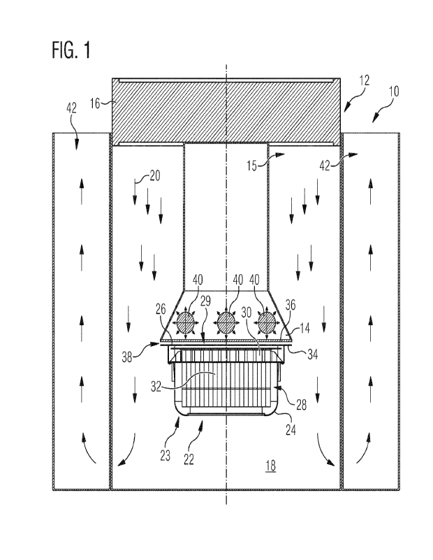
Fig. 1 shows a sterilizing device 10 and its transfer lock
12 in detail. A removal region of the sterilizing device 10
is not shown in the figure.
The transfer lock 12 comprises a cover unit 14, a
decontamination device 15 and a filter unit 16. The
transfer lock 12 is designed having a space 18 that can be
sealed in a gas-tight manner. Gas 20 containing hydrogen
peroxide, the direction of flow of which is represented by
7648689
CA 03164393 2022- 7- 11
16
arrows, can be introduced into the space 18 via the
decontamination device 15.
A receptacle 22 to be sterilized and having an outer face
23 is arranged in the space 18 below the cover unit 14. The
receptacle 22 comprises a receptacle body 24 and a lidding
foil 26 which together form the outer face 23. The
receptacle body 24 is designed in the manner of a trough
and comprises a receiving space 28. The receiving space 28
opens into a removal opening 29 (pointing upward in the
present case), which is closed by the lidding foil 26. In
the present example, the receiving space 28 is consequently
delimited by the receptacle body 24 and the lidding foil
26, in the present case completely (without further
delimiting elements).
A nest 30 is arranged inside the receiving space 28 and
comprises primary packaging 32 designed as syringes. The
lidding foil 26 is connected to the receptacle body 24 at a
laterally protruding edge 34. The lidding foil 26 is planar
and even. The receptacle body 24 is impermeable to both
germs and gases, in particular H202 in the gas phase
(gaseous or as a mist/aerosol). The lidding foil 26 is
impermeable to germs. The lidding foil 26 is permeable to
gases, in particular H202 in the gas phase (gaseous or as a
mist/aerosol).
The region around the cover unit 14 and the receptacle 22
is shown enlarged in Fig. 2.
7648689
CA 03164393 2022- 7- 11
17
In the state shown in Fig. 1 and 2, the receptacle 22 is
arranged such that the lidding foil is arranged in parallel
with a cover plate 36 of the cover unit 14. A gap 38 is
formed between the lidding foil and the cover plate, which
in the present case is formed having a gap width 39 of
0.5 cm.
The cover unit 14 comprises a plurality of radiation
sources 40 which are designed to emit UV radiation and can
each emit UV radiation in the direction of the lidding foil
26 through the cover plate 36. For this purpose, the cover
plate 36 is designed to be UV-permeable. This is
illustrated by corresponding arrows emanating from the
radiation sources 40.
The method according to the invention for sterilizing the
receptacle 22 is illustrated schematically in Fig. 3 using
the example of the operation of the sterilizing device 10.
In a first step 100, the receptacle 22 in outer packaging
is introduced into a removal region of the sterilizing
device 10 and a cleaned gas, for example cleaned air,
circulates therearound with a directed, laminar flow.
In a second step 200, the receptacle 22 is removed from the
outer packaging while the cleaned gas is circulating
therearound.
In a third step 300, the receptacle 22 is introduced into
the transfer lock 12, as is shown in Fig. 1, for example.
7648689
CA 03164393 2022- 7- 11
18
In a fourth step 400, the receptacle 22 is arranged in the
region of the cover unit 14 such that the cover unit 14
covers the region of the receptacle 22 formed by the
lidding foil. For this purpose, the cover unit 14 can be
held stationary and the receptacle 22 can be moved, or vice
versa. It is also possible for receptacle 22 and cover unit
14 to be moved in this step.
In a fifth step 500, the transfer lock 12 is flooded with a
H202-containing atmosphere. At the same time (directly
before or after is also possible), the lidding foil 26 of
the receptacle 22 is irradiated by means of the
electromagnetic radiation source 40 arranged in the cover
unit 14, which is designed as a UV radiation source in the
example from Fig. 1.
In order to flood the transfer lock with the H202-
containing atmosphere, the gas 20 flows past the receptacle
22 in a laminar flow from the side of the cover unit 14. On
a side of the receptacle 22 arranged opposite the cover
unit 14, the gas 20 is carried away from the receptacle 22
via a return air duct 42 or a plurality of return air ducts
42, which are arranged to the side of the cover unit 14.
The gas 20 can then be cleaned, for which purpose, for
example, catalytic decomposition of the H202 in the gas can
be used.
7648689
CA 03164393 2022- 7- 11
19
In a sixth step 600, the transfer lock is flushed with
H202-free gas and the receptacle 22 is removed from the
transfer lock 12.
7648689
CA 03164393 2022- 7- 11