Note: Descriptions are shown in the official language in which they were submitted.
WO 2021/154592
PCT/US2021/014527
SYRINGE ACTUATED STOPCOCK SMART-VALVE
CROSS-REFERENCE TO RELATED APPLICATION
[0001] The present application claims priority to United States Provisional
Application Serial
No. 62/966,0g6, entitled "Syringe Actuated Stopcock Smart-Valve", filed
January 27, 2020, the
entire disclosure of which is hereby incorporated by reference in its
entirety.
BACKGROUND OF THE INVENTION
Field of the Disclosure
[0002] The present application relates generally to a medical stopcock.
Description of the Related Art
[0003] Stopcocks, such as 3-way stopcocks, include two input ports and one
output port. In
some configurations, a handle of the stopcock may be operated by a healthcare
professional to
place the stopcock in three positions, including where a first input port is
in fluid communication
with the output port, where a second input is in fluid communication with the
output port, and
where the first input port is in fluid communication with the second input
port. Stopcocks are
utilized in connection with a variety of situations, including use in
connection with a flow sensor
system that uses an ultrasonic flowmeter with a flow tube sub-assembly having
two piezoelectric
transducers coupled to a fluid flow tube. When a transducer is excited by an
electrical pulse,
ultrasonic waves are transmitted into the fluid and the flow tube. The flow
sensor system analyzes
the waves traveling through the fluid to determine a velocity, which is
proportional to a shift
between signals received from the upstream transducer and the downstream
transducer.
SUMMARY OF THE INVENTION
[0004] In one aspect or embodiment, a medical stopcock includes a main body
including an
input port and an output port, and a valve body including a handle and a
syringe port. The valve
body is moveable relative to the main body and defines a valve passageway. The
valve body
includes a first position where the input port and the output port are in
fluid communication via
the valve passageway, a second position where the syringe port and the output
port are in fluid
communication via the valve passageway, and a third position where the syringe
port and the input
port are in fluid communication via the valve passageway. Rotation of the
syringe port is
configured to move the valve body relative to the main body.
CA 03165062 2022- 7- 15
WO 2021/154592
PCT/US2021/014527
[0005] The syringe port and the valve body may he formed integrally_ The
syringe port, the
valve body, and the handle may be formed integrally. The main body may define
a valve opening,
with the valve body received within the valve opening. The syringe port may
include a threaded
connection, with the syringe port configured to rotate the valve body from the
first position to the
second position when a syringe barrel connected to the threaded connection of
the syringe port is
rotated. The syringe port may include a female luer connector. The input port
may include a
female luer connector and the output port may include a male luer connector.
The syringe port
may include a valve member having a sealed position and an open position, with
the valve member
of the syringe port to move from the sealed position to the open position when
a syringe barrel is
secured to the syringe port.
[0006] The valve body may include a position structure configured to be sensed
by a sensor to
determine whether the valve body is in the first position, the second
position, or the third position.
[0007] The position structure may be a recessed portion of the handle of the
valve body. The
valve body may include at least one indicator to provide an indication of
whether the valve body
is in the first position, the second position, or the third position.
[0008] The valve body may be configured to rotate 180 degrees relative to the
main body. The
syringe port may be in fluid communication with the input port and the output
port when the valve
body is in the first position.
[0009] The valve passageway may include a first portion, a second portion
extending in a first
direction perpendicular to the first portion, and a third portion extending in
a second direction
perpendicular to the first position. The third portion of the valve passageway
may be in fluid
communication with the syringe port when the valve body is in the first
position, the second
position, and the third position.
BRIEF DESCRIPTION OF THE DRAWINGS
[0010] The above-mentioned and other features and advantages of this
disclosure, and the
manner of attaining them, will become more apparent and the disclosure itself
will be better
understood by reference to the following descriptions of aspects of the
disclosure taken in
conjunction with the accompanying drawings, wherein:
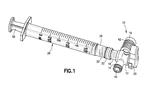
[0011] FIG. 1 is a perspective view of a stopcock according to one aspect or
embodiment of the
present application, showing the stopcock connected to a syringe.
2
CA 03165062 2022- 7- 15
WO 2021/154592
PCT/US2021/014527
[0012] FIG. 2 is an exploded perspective view of the stopcock of FIG. 1.
[0013] FIG. 3 is a bottom perspective view of the stopcock of FIG. 1, showing
a first position
of the stopcock.
[0014] FIG. 4 is a cross-sectional view along line 4-4 in FIG. 3.
[0015] FIG. 5 is a bottom perspective view of the stopcock of FIG. 1, showing
a second position
of the stopcock.
[0016] FIG. 6 is a cross-sectional view along line 6-6 in FIG. 5.
[0017] FIG. 7 is a bottom perspective view of the stopcock of FIG. 1, showing
a third position
of the stopcock.
[0018] FIG. 8 is a cross-sectional view along line 8-8 in FIG. 7.
[0019] FIG. 9 is a top perspective view of the stopcock of FIG. 1.
[0020] FIG. 10 is a cross-sectional view taken along line 10-10 in FIG. 9.
[0021] FIG. 11 is a right-side perspective view of a valve body of the
stopcock of FIG. 1 with a
portion of the valve body being transparent for clarity.
[0022] FIG. 12 is a left-side perspective view of a valve body of the stopcock
of FIG. 1 with a
portion of the valve body being transparent for clarity.
[0023] Corresponding reference characters indicate corresponding parts
throughout the several
views. The exemplifications set out herein illustrate exemplary aspects of the
disclosure, and such
exemplifications are not to be construed as limiting the scope of the
disclosure in any manner.
DETAILED DESCRIPTION
[0024] The following description is provided to enable those skilled in the
art to make and use
the described aspects contemplated for carrying out the invention. Various
modifications,
equivalents, variations, and alternatives, however, will remain readily
apparent to those skilled in
the art. Any and all such modifications, variations, equivalents, and
alternatives are intended to
fall within the spirit and scope of the present invention.
[0025] For purposes of the description hereinafter, the terms "upper",
"lower", "right", "left",
"vertical", "horizontal", "top", "bottom", "lateral", "longitudinal", and
derivatives thereof shall
relate to the invention as it is oriented in the drawing figures. However, it
is to be understood that
the invention may assume various alternative variations, except where
expressly specified to the
contrary. It is also to be understood that the specific devices illustrated in
the attached drawings,
3
CA 03165062 2022- 7- 15
WO 2021/154592
PCT/US2021/014527
and described in the following specification, are simply exemplary aspects of
the invention.
Hence, specific dimensions and other physical characteristics related to the
aspects disclosed
herein are not to be considered as limiting. All numbers and ranges used in
the specification and
claims are to be understood as being modified in all instances by the term
"about-. By "about" is
meant plus or minus twenty-five percent of the stated value, such as plus or
minus ten percent of
the stated value. However, this should not be considered as limiting to any
analysis of the values
under the doctrine of equivalents.
[0026] Unless otherwise indicated, all ranges or ratios disclosed herein are
to be understood to
encompass the beginning and ending values and any and all subranges or
subratios subsumed
therein. For example, a stated range or ratio of "1 to 10" should be
considered to include any and
all subranges or subratios between (and inclusive of) the minimum value of 1
and the maximum
value of 10; that is, all subranges or subratios beginning with a minimum
value of 1 or more and
ending with a maximum value of 10 or less. The ranges and/or ratios disclosed
herein represent
the average values over the specified range and/or ratio.
[0027] The terms "first", "second", and the like are not intended to refer to
any particular order
or chronology, but refer to different conditions, properties, or elements.
[0028] Referring to FIGS. 1-12, in one aspect or embodiment, a medical
stopcock 10 includes
a main body 12 having an input port 14 and an output port 16, and a valve body
18 having a handle
20 and a syringe port 22. The valve body 18 is moveable relative to the main
body 12 and defines
a valve passageway 24. The valve body 18 includes a first position (FIGS. 3
and 4) where the
input port 14 and the output port 16 are in fluid communication via the valve
passageway 24, a
second position (FIGS. 5 and 6) where the syringe port 22 and the output port
16 are in fluid
communication via the valve passageway 24, and a third position (FIGS. 7 and
8) where the syringe
port 22 and the input port 14 are in fluid communication via the valve
passageway 24. Rotation
of the syringe port 22 is configured to move the valve body 18 relative to the
main body 12, which
is discussed in more detail below. In one aspect or embodiment, the syringe
port 22 is in fluid
communication with the input port 14 and the output port 16 when the valve
body 18 is in the first
position. In FIGS. 1-8, the stopcock 10 is shown connected to a syringe 26
having a syringe barrel
28 with a male luer connector 30, although other suitable syringes may be
utilized. The medical
stopcock 10 may be utilized in connection with a flow sensor system, such as
the flow sensor
4
CA 03165062 2022- 7- 15
WO 2021/154592
PCT/US2021/014527
system disclosed in U.S. Patent No. 9,970,794, which is hereby incorporated by
reference in its
entirety.
[0029] Referring to FIGS. 3-8, the syringe port 22, the valve body 18, and the
handle 20 are
formed integrally. The syringe port 22, the valve body 18, and the handle 20,
however, may be
formed integrally, may be separately formed, and combinations thereof. The
main body 12 defines
a valve opening 32, with the valve body 18 received within the valve opening
32.
[0030] Referring again to FIGS. 1-12, the syringe port 22 includes a threaded
connection 34,
with the syringe port 22 configured to rotate the valve body 18 from the first
position to the second
position when the syringe barrel 28 connected to the threaded connection 34 of
the syringe port 22
is rotated. Therefore, a healthcare professional can move the valve body 18
from the first position
to the second position via the syringe 26. In other words, once the threaded
connection 34 of the
syringe port 22 is engaged with the luer connector 30 of the syringe barrel
28, further rotation of
the syringe barrel 28, such as a clockwise rotational direction, causes the
valve body 18 to rotate
relative to the main body 12 with the valve body 18 moving from the first
position to the second
position. In one aspect or embodiment, the threaded connection 34 of the
syringe port 22 is a two-
start thread, which can be aligned one-half turn apart as a starting position
such that the syringe
barrel 28 may be secured to the threaded connection 34 by rotating the syringe
26 180 degrees
clockwise until the connection is secured. Further rotation of the syringe 26
90 degrees clockwise
moves the valve body 18 from the first position to the second position. A
healthcare professional
may move the valve body 18 to and from each of the first position, the second
position, and the
third position using the handle 20 of the valve body 18. In one embodiment or
aspect, the valve
body 18 and the valve opening 32 of the main body 12 have a tight fit, which
may require a user
to use the handle 20 to move the valve body 18. In one embodiment or aspect,
the valve body 18
and the valve opening 32 of the main body 12 have a loose fit, which
facilitates movement of the
valve body 18 via the syringe 26 when the syringe 26 is connected to the
syringe port 22.
[0031] In one aspect or embodiment, the valve body 18 and/or main body 12
includes an
indicator structure (not shown) to provide an audible and/or tactile
indication when the valve body
18 is in the first position. An audible and/or tactile indication may also be
provided when the valve
body 18 reaches the second and third positions. In one aspect or embodiment,
the valve body 18
and/or main body 12 includes one or more stops (not shown) to restrict
movement of the valve
body 18 to movement between the first position, the second position, and the
third position. In
CA 03165062 2022- 7- 15
WO 2021/154592
PCT/US2021/014527
one aspect or embodiment, the valve body 18 is configured to rotate 180
degrees relative to the
main body 12.
[0032] Referring to FIGS. 3-8, the syringe port 22 includes a female luer
connector 38, although
other suitable connectors may be utilized. The input port 14 includes a female
luer connector 40
and the output port 16 includes a male luer connector 42 with a spinning luer
lock, although other
suitable connectors may be utilized. The syringe port 22 includes a valve
member 44 having a
sealed position and an open position, with the valve member 44 configured to
move from the
sealed position to the open position when the syringe 26 is secured to the
syringe port 22. Although
not shown in FIGS. 1-8, when the syringe 26 is connected to the syringe port
22, the male luer
connector 30 of the syringe 26 engages the valve member 44 of the syringe port
22 to move or
retract the valve member 44 from the sealed position to the open position
thereby placing the
syringe barrel 28 in fluid communication with the syringe port 22.
[0033] Referring to FIGS. 3, 5, and 7, the valve body 18 includes a position
structure 46
configured to be sensed by a sensor to determine whether the valve body 18 is
in the first position,
the second position, or the third position. In one aspect or embodiment, the
position structure 46
is a recessed portion of the handle 20 of the valve body 18. The position
structure 46 may act as
a flag or shutter that can be sensed by an external sensor or mechanism to
determine the position
of the valve body 18. The valve body 18 includes at least one visual indicator
48 to provide an
indication of whether the valve body 18 is in the first position, the second
position, or the third
position. The visual indicator 48 may be an arrow, text, shape of the handle
20, or any other suitable
indication arrangement.
[0034] Referring to FIGS. 9-12, the valve passageway 24 includes a first
portion 52, a second
portion 54 extending in a first direction perpendicular to the first portion
52, and a third portion 56
extending in a second direction perpendicular to the first portion 52. The
third portion 56 of the
valve passageway 24 is in fluid communication with the syringe port 22 when
the valve body 18
is in the first position, the second position, and the third position.
[0035] In a further aspect or embodiment of the present application, a method
of using the
stopcock 10 includes: securing the syringe 26 to the syringe port 22 and
continuing to rotate the
syringe 26 until the valve body 18 of the stopcock 10 moves from the first
position to the second
position; performing an injection with fluid being transferred from the
syringe 26 to the output
6
CA 03165062 2022- 7- 15
WO 2021/154592
PCT/US2021/014527
port 16; and returning the valve body 18 to the first position using the
handle 20 of the valve body
18.
[0036] In one aspect or embodiment, the method further includes: moving the
valve body 18 to
the third position using the handle 20 of the valve body 18; retracting a
plunger 58 of the syringe
26 to draw fluid from an IV line (not shown) connected to the input port 14
into the syringe barrel
28; and injecting saline flush fluid using the syringe 26 to force fluid
through the output port 16.
The syringe 26 may be disconnected from the syringe port 22 by rotating the
syringe 26 in a
counterclockwise direction.
[0037] While this disclosure has been described as having exemplary designs,
the present
disclosure can be further modified within the spirit and scope of this
disclosure. This application
is therefore intended to cover any variations, uses, or adaptations of the
disclosure using its general
principles. To the extent possible, one or more features of any embodiment or
aspect can be
combined with one or more features of any other embodiment or aspect. Further,
this application
is intended to cover such departures from the present disclosure as come
within known or
customary practice in the art to which this disclosure pertains and which fall
within the limits of
the appended claims.
7
CA 03165062 2022- 7- 15