Note: Descriptions are shown in the official language in which they were submitted.
CA 03165089 2022-06-16
WO 2021/130129 PCT/EP2020/087138
MAGNETIC INDUCTION TOMOGRAPHY APPARATUS AND METHOD FOR
MONITORING A MULTIPHASE FLUID
The present invention relates to a method of, and an apparatus for, monitoring
a multiphase
fluid using magnetic induction tomography. The multiphase fluid comprises
fluids, and may
comprise a mixture of liquids, or one or more liquids in a mixture with solids
and/or gases. The
fluid may be static or dynamic, for example a multiphase flow in a fluid
conduit. This invention
particularly relates to a monitoring apparatus and method which has a number
of applications,
in particular within the oil and gas exploration and production industry.
A number of prior patent specifications in the name of the Applicant are
directed to the use of
Magnetic Induction Tomography (MIT), either used alone or in conjunction with
other
techniques, for monitoring a multiphase flow in a pipe, in particular in the
oil and gas
exploration and production industry.
In particular, GB2513678B discloses an "Oil well system and operating method
including
monitoring multiphase flow in a pipe", GB2513679B discloses a "Method of
defining a
multiphase flow comprising three phases", GB2507368B discloses "Method and
apparatus for
monitoring the flow of mixtures of fluids in a pipe", GB2534337B discloses
"Method and
apparatus for monitoring of the multiphase flow in a pipe" and GB2530601B
discloses
"Method and apparatus for monitoring of the multiphase flow in a pipe". In
addition,
GB2527324B discloses a "Segmented Electromagnetic Sensor".
In these prior specifications, transmitting and receiving coils are located
around the outside of
a pipe. The transmitting coil(s) are supplied with a varying current which
transmits
electromagnetic field into a multiphase flow within the pipe. The
electromagnetic field induces
eddy currents in an electrically conductive phase within the pipe resulting in
a secondary
electromagnetic field. The secondary electromagnetic field induces an electric
field which can
be measured in the receiving coil(s) via voltage output that can be analysed
to determine
properties of the multiphase flow.
It is disclosed is these specifications that electromagnetic energy can
provide information
related to certain physical properties of materials in the multiphase flow
exposed to this type
of energy. When used in an electromagnetic flowmeter, electrical capacitance
tomography
(ECT), electrical resistance tomography (ERT) and magnetic inductance
tomography (MIT)
can be used to interrogate the multiphase flow. In each case a varying
electric or magnetic
field can be applied across the multiphase flow, and measurements of voltage,
current and
1
CA 03165089 2022-06-16
WO 2021/130129 PCT/EP2020/087138
magnetic field can be used to measure certain physical parameters of the
constituent
components of the multiphase flow.
It is known to use magnetic inductance tomography (MIT) to measure a contrast
in electrical
conductivity between, on the one hand, an electrically conductive medium (e.g.
an aqueous
phase) and, on the other hand, an electrically non-conductive medium (e.g. an
oil phase). When
measuring fluid conductivity, for example in a multiphase flow, a high
frequency (1-30MHz)
magnetic field is typically used. In these conditions, it has been assumed in
the state of the art
that the displacement current induced by electrical permittivity is small
compared to the eddy
current induced by electrical conductivity, and therefore the displacement
eddy current is
ignored. Therefore the electrical permittivity, relating to the dielectric
properties of an
electrically non-conductive phase, has not been measured using such
applications of magnetic
inductance tomography (MIT).
It is known in the art to use two separate systems to measure the phase and
amplitude of a
complex voltage induced by various fluids in a multiphase flow, the two
separate systems
usually respectively operating at two different frequencies.
It is known to combine an MIT apparatus configured to measure electrical
conductivity with
another apparatus configured to measure electrical permittivity in a composite
system to
measure both the electrical conductivity and the electrical permittivity in a
region of interest.
However, the primary problem with this measurement technique is that the use
of two apparatus
requires the operation of the respective apparatus, i.e. the MIT apparatus
configured to measure
electrical conductivity and the other apparatus configured to measure
electrical permittivity, to
take place in sequence, both in time and in space. This measurement technique
therefore suffers
from the problem of both temporal and spatial lags between two sets of
measurements, i.e.
electrical conductivity and electrical permittivity.
A recent paper (Yazdanian, H. and Jafari, R. (2018) 'Improvement on
Conductivity Image
Reconstruction in Magnetic Induction Tomography', in IEEE Transactions on
Instrumentation
and Measurement, pp. 1-5) disclosed that magnetic induction tomography (MIT)
was used to
image the conductivity and permeability properties of a target inside an
object based on
electrical impedance measurements from excitation and detection coils. Both
real and
imaginary parts of the induced voltages were used in conductivity image
reconstruction for
both low and high conductivity applications. The imaginary and real components
of the
complex voltage were de-multiplexed and the effect on the conductivity and
permeability
2
CA 03165089 2022-06-16
WO 2021/130129 PCT/EP2020/087138
properties were evaluated separately for the imaginary and real components.
Although the prior art summarised above discloses a method of, and a
monitoring apparatus
for, monitoring a multiphase fluid, for example a flow in a pipe, using
magnetic induction
tomography (MIT) which can effectively monitor such a multiphase fluid, there
is nevertheless
a need in the art for an improved monitoring apparatus and method.
In particular, there is a need in the art for a monitoring apparatus and
method which has an
enhanced sensitivity to distinguish between an electrically conductive phase
such as an aqueous
phase, for example water, and an electrically non-conductive phase, such as an
oil phase or a
solid phase such as sand, in a multiphase fluid, for example in a multiphase
flow.
The present invention aims, at least partially, to meet this need in the art,
particularly in the
field of oil and gas exploration and production, to provide enhanced
analytical data in real-time
on the phase composition of a multiphase fluid, particularly a multiphase flow
within a pipeline
used in the oil and gas industry. However the invention also has application
for the monitoring
of static multiphase fluids, and in other applications in different technical
and commercial
fields.
The present invention accordingly provides a monitoring apparatus for
monitoring a
multiphase fluid according to claim 1.
The present invention further provides a method of monitoring a multiphase
fluid according to
claim 14.
Preferred features of the respective apparatus and method of the present
invention are defined
in the dependent claims.
When monitoring a multiphase flow in a pipe using magnetic induction
tomography, when the
multiphase flow includes an electrically conductive phase, such as an aqueous
phase, for
example water, various parameters may be relevant to define the performance
and accuracy of
the monitoring.
The present invention is at least partly predicated on the finding by the
present inventors that
in a multiphase flow, the permittivity and conductivity of the mixed fluid
vary in both the
temporal and spatial domains, and both the electrical permittivity-induced
displacement current
and the electrical permittivity-induced eddy current contribute to the induced
magnetic field
that results in the measured voltage change.
3
CA 03165089 2022-06-16
WO 2021/130129 PCT/EP2020/087138
Unexpectedly, for example as compared to the Yazdanian and Jafari, 2018 paper
discussed
above, the present inventors have identified that the effect of permittivity
in the overall
amplitude signal is at least 1 order of magnitude greater than that observed
by independently
measuring the real and imaginary components separately. This effect is thought
to be associated
to the inverse effect that the conductivity has on both amplitude components,
decreasing the
dynamic range of the absolute amplitude signal, and hence increasing the
relative impact of the
permittivity in the measurement.
Accordingly, the effect of either of these two displacement currents should
not be ignored in
order to accurately achieve accurate data processing of the multiphase flow
using magnetic
induction tomography (MIT) apparatus. The temporal, spatial and frequency
related
permittivity and conductivity changes are all reflected in the changes in the
induced electrical
voltage which is measured by the magnetic induction tomography (MIT)
apparatus.
The induced electrical voltage is a complex voltage having both an amplitude
and a phase. The
electrical permittivity of the measured multiphase fluid, in particular the
electrical permittivity
of the electrically non-conductive phase, affects the measured amplitude of
the complex
voltage and the electrical conductivity of electrically conductive phase
affects both the
measured amplitude of the complex voltage and the measured phase angle of the
complex
voltage.
In this specification, the phase angle measurement, typically expressed as cp
in radians, is
defined by the phase angle of the induced complex voltage from a receiving
coil relative to a
reference due to the induced eddy currents (/
v eddy) around a conductive medium in the region
of interest. The phase angle is measured relative to a reference, which is
typically relative to
the phase of the exciting magnetic field.
In this specification, the phase difference or phase shift, typically
expressed as Acp in radians,
is defined by the difference between the phase angle of the induced voltage
from a coil due to
a change in conductivity arising from change in medium structure, motion, an
external
environment (in either the spatial or time domains), as well as frequency-
dependent
characteristics, relative to a reference, typically the phase angle of the
exciting magnetic field.
The present inventors have found that by measuring both the electrical
permittivity and the
electrical conductivity of the measured multiphase fluid, the resultant
amplitude and phase
angle of the induced complex voltage can be analysed. The phase angle data can
be analysed
4
CA 03165089 2022-06-16
WO 2021/130129 PCT/EP2020/087138
to provide information on the electrically conductive phase, and that
information can be
employed to analyse the amplitude data, in particular to use the information
on the electrically
conductive phase to determine the contribution to the amplitude data by the
electrically non-
conductive phase. This analytical technique enables the electrical
permittivity of the
electrically non-conductive phase to be accurately determined. By determining
the degree of
contribution to the complex voltage measurement by both the permittivity and
the conductivity,
enhanced measurement accuracy of a multiphase fluid can be achieved.
In other words, the measurement of the properties of the electrically non-
conductive phase can
be enhanced by calculation from data including the measured properties of the
electrically
conductive phase.
Also, the data processing can be enhanced to provide a precise fluid phase or
flow pattern using
MIT.
Furthermore, the permittivity and the conductivity measurements on the
multiphase fluid can
be carried out using a single combination of a magnetic field generator and a
voltage detector,
i.e. using a single magnetic induction tomography (MIT) apparatus, thereby
avoiding any
temporal or spatial variation in the permittivity and the conductivity
measurements, which
further enhances measurement accuracy and data processing.
Accordingly, the preferred embodiments of the present invention can avoid the
need, as known
in the state of the art, to use two separate apparatus to measure the phase
and amplitude of a
complex voltage induced by various fluids in a multiphase flow. The preferred
embodiments
of the present invention can provide that both the amplitude and phase angle
of a complex
voltage can be measured, typically simultaneously, using a single magnetic
induction
tomography apparatus having a common magnetic field generator and voltage
detector
assembly.
This preferred embodiments of the present invention can provide one magnetic
induction
tomography apparatus which can be used to measure both the phase shift and
amplitude of the
complex voltages to continuously monitor and measure the phase fraction,
typically the volume
phase fraction, of conductive and non-conductive phases in a multiphase flow.
The use of only
one magnetic induction tomography apparatus to measure both of these
parameters, typically
simultaneously, can remove the need to co-locate two separate systems, and
therefore improves
the measurement accuracy as compared to the known use of two separate
apparatus.
CA 03165089 2022-06-16
WO 2021/130129 PCT/EP2020/087138
In particular, the preferred embodiments of the present invention can provide
the technical
effects and advantages of: simultaneous measurement of the conductivity and
permittivity of a
multiphase fluid using one MIT apparatus; real time derivation and
verification of the
conductive and non-conductive phase volumetric fractions from conductivity and
permittivity
measurements using one MIT apparatus; removing the need to co-locate two
separate MIT
systems over the same fluid volume, for example over the same pipe cross-
section, hence
enhancing flow measurement accuracy; and the improved analysed data of the
amplitude and
phase angle parameters can enable enhanced in-situ flow pattern imaging to be
achieved,
typically in real time.
The present invention relates specifically to an improved apparatus and method
for the use of
MIT (Magnetic Induction Tomography) to monitor multiphase fluids, in
particular in the
application of MIT to measuring multiphase flows in the oil and gas and other
industries. The
principle of MIT is that electric coils are excited with alternating current
that results in the coils
producing varying electromagnetic fields. The object of interest is placed
within these fields
and the varying field induces varying currents within the object that is
dependent on the
conductivity of the object. The varying currents in the object produce
secondary
electromagnetic fields that can be received by the same or other coils. The
received secondary
electromagnetic field in conjunction with the primary imposed electromagnetic
field can be
used to compute the conductivity contrast between the object and the material
that surrounds
it. In accordance with the present invention, the computation also generates
data representing
at least one property of at least one electrically conductive phase in the
multiphase fluid and at
least one property of at least one electrically non-conductive phase in the
multiphase fluid.
In particular, the electrical conductivity of an electrically conductive phase
can be accurately
measured to enable the spatial, and preferably also the temporal, location of
the electrically
conductive phase to be accurately determined, and in addition, the electrical
permittivity of an
electrically non-conductive phase can also be accurately calculated, the
calculation using
measured phase angle data related to electrical conductivity and amplitude
data related to
electrical conductivity, and electrical permittivity, to enable the spatial,
and preferably also the
temporal, location of the electrically non-conductive phase to be accurately
determined. The
resultant data can be used to produce an image of the multiphase fluid in real
time.
In the preferred embodiments of this invention, the amplitude of the measured
complex voltage
is used to monitor the permittivity properties of the electrically non-
conductive phase, and
6
CA 03165089 2022-06-16
WO 2021/130129 PCT/EP2020/087138
provide output data that can more accurately represent the location of the
electrically non-
conductive phase in space and optionally time. For a flowing multiphase fluid,
the flow
measurement and flow pattern can be more accurately measured and identified.
The preferred embodiments of this invention relate to an apparatus and method
to measure the
flow of mixtures of fluids from a well or group of wells during oil and gas
exploration,
production or transportation operations. However, it should be understood that
the apparatus
and method of the present invention may be used in other potential
applications, as those skilled
in the art will appreciate. For example, the apparatus and method of the
present invention may
be used in fluid or flow measurement devices, medical MIT Systems involving
measurement
of low conductivity contrasts of multiphase fluids, optionally multiphase
fluid flows, and
multiphase fluid process monitoring equipment.
Embodiments of the present invention will now be described, by way of example
only, with
reference to the accompanying drawings, in which:
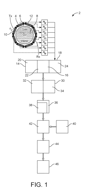
Figure 1 is a schematic illustration of a monitoring apparatus for monitoring
a multiphase fluid,
as flow through a pipe, in accordance with an embodiment of the present
invention;
Figure 2 is a schematic process flow of a method of monitoring a multiphase
flow using the
apparatus of Figure 1;
Figure 3 is a graph showing the relationship between phase angle and
conductivity according
to a first model used in an example of a method of monitoring a multiphase
flow using the
apparatus of Figure 1;
Figure 4 is a graph showing the relationship between voltage and conductivity,
at different
permittivity values, according to a second model used in an example of a
method of monitoring
a multiphase flow using the apparatus of Figure 1; and
Figure 5 is a schematic process flow used in an example of a method of
monitoring a multiphase
flow using the apparatus of Figure 1.
Referring to Figure 1, there is shown a monitoring apparatus 2 for monitoring
a multiphase
flow in a pipe using magnetic induction tomography. However the apparatus and
method of
the present invention can be used to monitor any multiphase fluid within an
interior volume
defined by a body. The multiphase fluid may comprise any mixture of liquid and
gas phases,
and the liquid phase may comprise aqueous and/or oil phases. Moreover, the
multiphase fluid
7
CA 03165089 2022-06-16
WO 2021/130129 PCT/EP2020/087138
may comprise a solid phase within the fluid. The multiphase fluid may be
static or dynamic.
The body may be a pipe or any other body for containing a multiphase fluid.
In the illustrated embodiment, the apparatus 2 surrounds a pipe 4 defining a
flow conduit 6. In
use, a multiphase flow 8 flows along the flow conduit 6 of the pipe 4. The
multiphase flow 8
comprises at least two phases, optionally at least three phases, further
optionally all of the
phases, selected from an oil phase, an aqueous phase, a solid phase and a
gaseous phase. In
Figure 1, four phases are shown schematically in stratified form, comprising a
continuous gas
phase, a continuous oil phase, a continuous aqueous (e.g. water) phase and a
continuous solid
(e.g. sand). However the apparatus and method of the present invention can be
used to monitor
both continuous and discontinuous phases in a multiphase fluid. The multiphase
flow 8
typically has a primary or continuous phase of the flow, e.g., oil, water or
gas, and within the
primary phase one or more other phase constituents may be present, for example
a solid phase,
e.g. sand. The flow regime of these phases can vary significantly depending on
the
concentrations of each phase and the flow rate. Typically, the phases are not
stratified, as shown
in Figure 1, but are irregularly mixed.
A plurality of coils 10, forming a coil assembly 12, are disposed
circumferentially around the
pipe 4. In the illustrated embodiment, eight coils 10 are disposed
circumferentially around the
pipe 4, the coils 4 being planar so that the coil assembly 12 forms an
octagonal cross-section
surrounding the pipe 4. Those skilled in the art will appreciate that more
coils could be used to
provide more measurements across the pipe 4. Each coil 10 faces an opposite
coil 10 of the coil
assembly 12, and the opposing coils 10 are on diametrically opposite sides of
the pipe 4.
Preferably, each coil 10 has a central axis which is orthogonal to a
longitudinal axis of the pipe
4, and the central axis of the coils 10 lie in a common plane which is
orthogonal to the
longitudinal axis of the pipe 4.
The portion of the pipe 4 surrounded by the coil assembly 12 is preferably
composed of a
material, for example a non-metallic material such as a polymer, which permits
electromagnetic field penetration, across a broad wavelength range, emitted
from one of the
coils 10 to pass through the multiphase material in the flow conduit 6 and
then secondary
induced electromagnetic radiation to be received by another of the coils 10.
In the illustrated embodiment, each of the coils 10 may be adapted to transmit
an
electromagnetic field into the flow conduit 6 when energized by an input
electrical signal
and/or to receive an electromagnetic field from the flow conduit 6 and
generate an output
8
CA 03165089 2022-06-16
WO 2021/130129 PCT/EP2020/087138
electrical signal, as described in detail hereinafter. The coils 10 may
alternate between
functioning as a transmitter and as a receiver. Accordingly for the
illustrated embodiment, in
use, each coil 10 is configured to function, in one operating cycle, as a
transmitter coil,
indicated by Tx, and to function, in a subsequent operating cycle, as a
receiver coil, indicated
by Rx. However, in an alternative embodiment one or more coils 10 may always
function as a
transmitter and one or more other coils 10 may always function as a receiver.
In in an alternative embodiment, there can be as few as two coils 10 around
the pipe 4.
However, preferably there are more than two coils 10 around the pipe 4.
Fundamentally, any
arrangement or control of the coils 10 may be employed which can transmit an
electromagnetic
field into multiphase flow 8 in the flow conduit 6 and receive a resultant
electromagnetic field
from the multiphase flow 8 in the flow conduit 6, and thereby generate an
output electrical
signal to be used to analyse the phase composition of the multiphase flow 8
using magnetic
induction tomography.
In the illustrated embodiment, in a first operating cycle one of the coils 10
is driven as a
transmitter and the remaining coils 10 are configured as receivers, so that
when there is a total
of eight coils 10, seven signals are received by the coils 10 functioning as
receivers.
The coils 10 are electrically connected to a controller 18. The controller 18
comprises a driver
20 for providing alternating electrical current, i.e. AC current, at a
selected frequency to the
transmitter coil(s) 10. Typically, the AC current has a frequency of from 1
kHz to 30 MHz, for
example from 1 kHz to 10 MHz. The combination of the coil assembly 12 and the
driver 20
comprise a magnetic field generator 14 adapted to generate a magnetic field
within the flow
conduit 6 of the pipe 4, i.e. within an interior volume defined by a body, the
magnetic field
temporally varying according to at least one frequency, thereby to apply the
varying magnetic
field to a multiphase fluid within the volume.
The controller 18 also comprises a voltage measuring system 22, coupled to a
processor 24.
The voltage measuring system 22 receives the induced electrical current from
the receiver
coil(s) 10, and can measure an induced complex voltage. Accordingly, the
combination of the
coil assembly 12 and the voltage measuring system 22 comprise a voltage
detector 16 adapted
to measure an induced complex voltage which has been produced by
electromagnetic induction
from at least one phase of the multiphase fluid within the volume.
9
CA 03165089 2022-06-16
WO 2021/130129 PCT/EP2020/087138
The voltage measuring system 22 is preferably configured to be sensitive
enough to measure
voltage amplitudes in a microvolt range (i.e. to an accuracy of +/- 1 x 10' V)
and phase angles
to an accuracy of sub-milli degrees (i.e. to an accuracy of +/- 1 x 10⁻³ ).
The apparatus 2 further comprises a signal processor 24 for determining, from
the measured
induced complex voltage, both an amplitude and a phase angle of the complex
voltage, thereby
respectively to provide amplitude data and phase angle data. The signal
processor 24 is adapted
to determine the phase angle of the measured induced complex voltage by
comparing the phase
of the complex voltage and the phase of the magnetic field generated by the
magnetic field
generator 14. This can provide a measurement of the phase difference between
the driving
magnetic field and the induced complex voltage, using magnetic induction
tomography. The
amplitude and a phase angle of the complex voltage are preferably determined
simultaneously,
and in real time with respect to the magnetic field generator 14 and the
voltage measuring
system 22.
The apparatus 2 further comprises a data processor 30 for calculating, from
the amplitude data
and phase angle data, first output data from the amplitude data and second
output data from the
phase angle data. The first output data is a function of the electrical
permittivity, i.e. the
dielectric property, and electrical conductivity of the at least one phase of
the multiphase fluid.
The second output data is a function of the electrical conductivity of the at
least one phase of
the multiphase fluid. The first and second output data are preferably
determined
simultaneously, and in real time with respect to the magnetic field generator
14 and the voltage
measuring system 22.
The data processor 30 comprises a first module 32 adapted to calculate from
the amplitude data
a first parameter related to a displacement current induced in at least one
electrically non-
conductive phase in the multiphase fluid and at least one electrically
conductive phase in the
multiphase fluid, the first parameter being within the first output data. The
data processor 30
also comprises a second module 34 adapted to calculate from the phase angle
data a second
parameter related to an eddy current induced in at least one electrically
conductive phase in the
multiphase fluid, the second parameter being within the second output data.
The apparatus 2 further comprises an analyser 36 for processing the first and
second output
data to generate analysed data representing at least one property of at least
one electrically non-
conductive phase in the multiphase fluid and at least one property of at least
one electrically
conductive phase in the multiphase fluid.
CA 03165089 2022-06-16
WO 2021/130129 PCT/EP2020/087138
The analyser 36 is adapted to generate analysed data which represents,
directly or indirectly,
the respective phase fractions, preferably volumetric phase fractions, of at
least one electrically
non-conductive phase in the multiphase fluid and at least one electrically
conductive phase in
the multiphase fluid. The first and second output data are preferably
processed simultaneously,
and in real time with respect to the magnetic field generator 14 and the
voltage measuring
system 22.
In the preferred embodiment, the analyser 36 is adapted to process the first
and second output
data to generate first analysed data representing the electrical permittivity
of the at least one
electrically non-conductive phase in the multiphase fluid and second analysed
data representing
the electrical conductivity of the at least one electrically conductive phase
in the multiphase
fluid.
The analyser 36 comprises a third module 38 adapted to calculate, from the
second parameter
related to the at least one electrically conductive phase, a third parameter.
The third parameter
is related to a contribution to the displacement current of the first
parameter by the at least one
electrically conductive phase. The third module 38 is adapted to calculate
from the first
parameter and the third parameter a contribution to the displacement current
of the first
parameter by the at least one electrically non-conductive phase thereby to
generate the first
analysed data.
In the preferred embodiment, the apparatus 2 further comprises a memory 40
comprising first
stored data representing a relationship between electrical permittivity of at
least one known
electrically non-conductive phase and amplitude of a complex voltage measured
using a
magnetic field of known properties. The memory 40 also comprises second stored
data
representing a relationship between electrical conductivity of at least one
known electrically
conductive phase and phase angle of a complex voltage measured using a
magnetic field of
known properties.
The stored data correlating the electrical permittivity and amplitude of a
complex voltage, and
electrical conductivity and phase angle of a complex voltage has been acquired
based upon
prior testing of properties of various fluids, and potentially solids
suspended in fluids, to be
measured using the apparatus and method of this invention, for example, fluids
and solids
typically extracted from oil fields. The stored data includes parameters from
a variety of
different geometrical characteristics, multiphase concentrations and
operational parameters to
provide an electromagnetic model by the stored data. The model may be enhanced
by carrying
11
CA 03165089 2022-06-16
WO 2021/130129 PCT/EP2020/087138
out simulations together with experimental work for each potential multiphase
fluid scenario
to be tested, in order to increase the sensitivity to the measurement of
combined changes in
conductivity and permittivity that are relevant to the intended application,
i.e. different
conductivities and permittivities, in different combinations.
For example, for the potential measurement of multiphase fluid from an oil
field, various
individual values, and combinations thereof, of the conductivity and
permittivity of the phases
likely to be encountered when using the apparatus and method of the invention
are shown in
Table 1 below.
Table 1
Property / Fluid Air Oil Water
0 0 0.5, 0.15, 0.25, 0.35, 0.45,
Conductivity (S/m)
0.55, 1, 5
Dielectric Constant 1 1, 2, 2.8, 3, 3.2, 4, 5, 6.03, 80
(E/E0) 7.4, 10
Using this stored data and model that correlates simultaneous responses from
the system to
changes in permittivity and conductivity, the degree of correlation between
the measurements
and the electrical properties may be identified. The model may be validated
using three-phase
combinations of the fluids/solids of interest.
The apparatus 2 further comprises a comparator 42 for comparing a measured
value of an
amplitude of a measured complex voltage with the first stored data to provide
a selected value
of electrical permittivity correlated to the measured amplitude value, and/or
for comparing a
measured value of a phase angle of a measured complex voltage with the second
stored data of
a complex voltage to provide a selected value of electrical conductivity
correlated to the
measured phase angle value.
Accordingly, in the preferred embodiment of the present invention,
determination step 56,
calculation step 62 and analysing step 68 function to:
1) Identify, from the amplitude and phase angle data of the induced complex
voltage, the
weight of both the displacement current induced by the electrically non-
conductive
12
CA 03165089 2022-06-16
WO 2021/130129 PCT/EP2020/087138
phase, and the eddy current induced by the electrically conductive phase, in a
multiphase fluid, typically a multiphase flow;
2) Derive, using the weight parameters and stored data correlating measured
phase angle
to electrical conductivity and measured amplitude to electrical permittivity,
the
associated permittivity and conductivity of the multiphase fluid;
3) Derive the volumetric fraction associated with electrically conductive and
electrically
non-conductive phases.
The apparatus 2 further comprises an imaging module 44 adapted to process the
analysed data
to produce image data in a form representing the multiphase fluid within the
volume across at
least a portion of a cross-sectional area of the volume. Preferably, the image
data is provided
to a display device 46 for visually displaying a sequence of images
representing temporal
changes in the multiphase fluid within the volume.
The method of monitoring, by magnetic induction tomography, a multiphase fluid
within an
interior volume defined by a body using the apparatus of Figure 1 will now be
described. The
process flow is illustrated in Figure 2.
The method comprises the step 52 of generating a magnetic field within the
interior volume
defined by the body. The magnetic field temporally varies according to at
least one frequency,
thereby to apply the varying magnetic field to a multiphase fluid within the
volume, in Figure
1 the volume being the flow conduit 6 of the pipe 4.
For example, an electromagnetic field is transmitted from one of the coils 10
into the
multiphase flow 8. The multiphase flow 8, when the invention is being used in
the oil industry,
typically comprises an oil phase, and an aqueous phase, and optionally one or
both of a solid
phase and a gaseous phase.
The other coils 10 each receive an electromagnetic field from the eddy
currents induced in the
multiphase flow 8 and generates an output electrical signal therefrom. Each of
the coils 10 can
act as either a transmitting or receiving coil and can change between the two
transmitting and
receiving modes. As described above, an alternating electrical current,
preferably having a
frequency of from 1 kHz to 10 MHz, is switched through one of the coils 10 to
generate from
the respective energized coil 10 a local electromagnetic field which is
transmitted into the fluid
conduit 6.
13
CA 03165089 2022-06-16
WO 2021/130129 PCT/EP2020/087138
Thus a varying electric current is passed through the transmitting coil 10,
which may have the
properties of a sine wave, or another form, e.g. square wave, and all other
potential forms of
varying current are encompassed by the present invention. The varying electric
current passing
through the transmitting coil 10 generates a varying electromagnetic flux
through the
multiphase flow 8 that is within the pipe 4. Depending on the physical
properties of the different
phases that the electromagnetic flux lines interrogate and in particular the
electrical
conductivity contrast between the phases, for example the oil and aqueous
phases, a varying
current is induced in any electrically conductive phase. This induced current
in turn generates
a secondary varying electromagnetic field that propagates through the pipe 4
and is picked up
by each coil 10 that is used as a receiver. The secondary varying
electromagnetic field therefore
induces a varying current in the receiver coil 10, and this is associated with
a corresponding
induced complex voltage which has been produced by electromagnetic induction
from at least
one phase of the multiphase fluid within the volume. The induced complex
voltage is measured
by the voltage measuring system 22 in a measuring step 54.
The coils 10 can function in a fixed operating mode, i.e. one coil 10 acts as
a transmitting coil
and the other coil(s) 10 act(s) as one or more receiving coil(s), or in a
dynamic operating mode,
i.e. the coils 10 can be switched so as to alternate between functioning as a
transmitting coil
and as a receiving coil.
When more than two coils are provided, typically one coil may function as a
transmitter and
other coils may function as a receiver, so that, for example, at any point in
time there is one
coil that is transmitting and all of the other coils are receiving. Once all
the receiver coil signals
have been processed, one or more of the other coils becomes the transmitter
and again the
remainder are receivers and so forth.
It will be appreciated by those skilled in the art that the sequencing may
take place in any order
and that a complete cycle of measurements, that is, where every coil has been
the transmitter
once, can occur very rapidly with, e.g., 160 to 8000, or 500 to 5000,
measurement cycles every
second. This frequency is primarily limited only by the processing power of
the processor 24.
It will also be appreciated by those skilled in the art that after one
complete cycle of
measurements a mesh of properties is produced that can be processed to provide
a mesh or
image of the multiple phases across the section of the pipe.
Although this illustrated embodiment describes each coil being either a
transmitter or receiver,
alternatively, a configuration can be provided whereby certain coils are
always transmitters and
14
CA 03165089 2022-06-16
WO 2021/130129 PCT/EP2020/087138
others are always receivers. In other embodiments coils can be enclosed within
other coils so
that dedicated transmitter and receiver coils are at the same location. Those
skilled in the art
will appreciate that many combinations are possible and all such combinations
may be
employed in this invention.
By comparing the driving and induced currents using appropriate processing in
the processor
24, for example, the phase shift between the signals, allows the conductivity
contrast between
the materials of the multiphase flow to be computed.
The electromagnetic measurement as described above can provide phase
measurements where
there is an electrical conductivity contrast between the phases. This is
possible when the
different phases or constituents are static or flowing in a predominately
electrically conducting
(e.g. water) or electrically non-conducting (e.g. oil) primary phase.
In a step 56, the signal processor 24 determines, from the measured induced
complex voltage,
both an amplitude and a phase angle of the complex voltage. The phase angle of
the complex
voltage is determined by comparing the phase of the complex voltage and the
phase of the
magnetic field. This determination step 56 respectively provides amplitude
data 58 and phase
angle data 60.
In a subsequent step 62, first and second output data 64, 66 are calculated
from the amplitude
data 58 and phase angle data 60. In particular, the first output data 64 is
calculated from the
amplitude data 58 and the first output data 64 is a function of the electrical
permittivity and
electrical conductivity of the at least one phase of the multiphase fluid. The
second output data
66 is calculated from the phase angle data 60, and the second output data 66
is a function of
the electrical conductivity of the at least one phase of the multiphase fluid.
In a data storage step 88, first and second stored data 90, 92 are stored in
the memory 40. The
first stored data 90 represents a relationship between electrical permittivity
of at least one
known electrically non-conductive phase and amplitude of a complex voltage
measured using
a magnetic field of known properties. The second stored data 92 represents a
relationship
between electrical conductivity of at least one known electrically conductive
phase and phase
angle of a complex voltage measured using a magnetic field of known
properties.
In step 62, a measured value of an amplitude of a measured complex voltage is
compared with
the first stored data 90 to provide a selected value of electrical
permittivity correlated to the
measured amplitude value. In addition, in step 62, a measured value of a phase
angle of a
CA 03165089 2022-06-16
WO 2021/130129 PCT/EP2020/087138
measured complex voltage is compared with the second stored data 92 to provide
a selected
value of electrical conductivity correlated to the measured phase angle value.
In other words, the measured complex voltage can be interpreted to provide
vales of electrical
permittivity and electrical conductivity which represent the properties of the
phases in the
multiphase fluid.
In a subsequent step 68, the first and second output data 64, 66 are analysed
in analyser 36 to
generate analysed data 74 representing at least one property of at least one
electrically non-
conductive phase in the multiphase fluid and at least one property of at least
one electrically
conductive phase in the multiphase fluid.
In step 68, a first parameter 70 is calculated from the amplitude data 58. The
first parameter 70
is related to a displacement current induced in at least one electrically non-
conductive phase in
the multiphase fluid and at least one electrically conductive phase in the
multiphase fluid. The
first parameter 70 is within the first output data 64. Correspondingly in step
68 a second
parameter 72 is calculated from the phase angle data 60. The second parameter
72 is related to
an eddy current induced in at least one electrically conductive phase in the
multiphase fluid.
The second parameter 72 is within the second output data 66.
In analysing step 68, the first and second output data 64, 66 are processed to
generate first
analysed data 76 representing the electrical permittivity of the at least one
electrically non-
conductive phase in the multiphase fluid and second analysed data 78
representing the electrical
conductivity of the at least one electrically conductive phase in the
multiphase fluid.
A third parameter 80 is calculated from the second parameter 72 related to the
at least one
electrically conductive phase. The third parameter 80 is related to a
contribution to the
displacement current of the first parameter by the at least one electrically
conductive phase.
The first analysed data 76 is generated by calculating, from the first
parameter 70 and the third
parameter 80, a contribution to the displacement current of the first
parameter 70 by the at least
one electrically non-conductive phase.
The analysed data 74 generated in step 68 represents, directly or indirectly,
the respective phase
fractions, preferably the volumetric phase fractions, of at least one
electrically non-conductive
phase in the multiphase fluid and at least one electrically conductive phase
in the multiphase
fluid.
16
CA 03165089 2022-06-16
WO 2021/130129 PCT/EP2020/087138
The steps 56, 62 and 68 are performed by at least one processor.
The method further comprises the step 96 of processing the analysed data 74 to
produce image
data 98 in a form representing the multiphase fluid within the volume across
at least a portion
of a cross-sectional area of the volume. A sequence of images representing
temporal changes
in the multiphase fluid within the volume may be visually displayed.
In an alternative embodiment, each first coil 10 mat be circumferentially
offset in a direction
around the pipe 4, with respect to a respective adjacent second coil 12, to
reduce or minimise
direct electromagnetic coupling between the respective first and second coils
10, 12.
As described in the Applicant's prior patent specifications, the electrical
current may be
selectively switched through selected first coils 10 in an array to generate
from each energized
coil a local electromagnetic field. Typically, an impedance (not shown)
connected to at least
some of the respective selected coils in the array is provided to modify the
magnitude of the
local electromagnetic field generated from the respective energized coil
element.
In one embodiment, the electrical current may be selectively switched through
selected coils
in the array to provide a composite electromagnetic field generated from the
energized first
coils 10, when transmitting, and the energized first coils 10 have a
controllable focal point
within the pipe 4.
In another embodiment, the electrical current may be selectively switched
through selected first
coils 10 in the array 10 to provide a composite electromagnetic field received
by the second
coils 12, when receiving, from a controllable focal point within the pipe 4.
The controllable
focal point may be scanned across the array of first and second coils 10, 12
to scan the generated
electromagnetic field across a cross-section of the pipe 4 and/or along a flow
direction along
the pipe 4. The scanning of the controllable focal point may be across a
plurality of points to
provide a pixelated image of the multiphase flow.
As described in the Applicant's prior patent specifications as summarised
above, in alternative
embodiments respective pairs of transmitting and receiving coils may be
separated by a known
fixed distance along the flow direction of the pipe. Each pair of transmitting
and receiving coils
may be operated as described above and can provide independent meshes or
images of the flow
at two points along the pipe. It is possible to cross-correlate the
measurements from two
transmitter/receiver pairs, in order to establish the time-of-flight of
features that represent
different phases in the multiphase flow. The time difference between the
features provides the
17
CA 03165089 2022-06-16
WO 2021/130129 PCT/EP2020/087138
time it takes for the phase to travel over the fixed distance. Those skilled
in the art will
appreciate that the velocity of this phase is readily computed from this
information.
Correspondingly, a velocity profile across the cross section of the pipe may
be obtained. That
is, a mesh or image of velocities can be produced that can be used to
establish the velocity
differences between the primary/continuous phase, and any other phase. Such
velocities can be
obtained when the primary or continuous phase is either conducting (e.g.
water) or non-
conducting fluid (e.g. oil).
Furthermore, alternative embodiments of the monitoring apparatus of the
present invention for
monitoring a multiphase flow in a pipe using magnetic induction tomography may
comprise a
plurality of, for example two, annular arrays of the transmitter/receiver
coils 10, 12 disposed
around the pipe 4 which defines therein an imaging space. In the first array,
each first coil 10
is adapted to transmit an electromagnetic field when energized by an input
electrical signal,
and in the second array each second coil 12 is adapted to receive an
electromagnetic field and
generate an output electrical signal.
The present invention will now be described further with reference to the
following non-
limiting Example.
Example
A monitoring apparatus 2 as shown in Figure 1 is provided, as also shown in
Figure 5. A
multiphase flow 8 flows along the flow conduit 6 defined by the pipe 4. The
driver 20 provides
an alternating current to the coils 10 to generate a magnetic field within the
multiphase flow 8,
as shown by step 52 of Figure 2.
The voltage measuring system 22 receives and in step 54 measures the induced
complex
voltages, representative of the electromagnetic properties of the mixed
multiphase flow 8.
The signal processor 24 processes the measured complex voltages from a number
of coils 10
in step 56 to output both phase angle data 60 and amplitude data 58.
Table 1 explains the symbols shown in Figure 5.
Table 1
18
CA 03165089 2022-06-16
WO 2021/130129 PCT/EP2020/087138
Symbol
(I) Phase angle
Conductivity
V Voltage
amplitude
Permittivity
a Volumetric
fraction
Mixture
Water
o Oil
Gas
xy Pixel
position
hydrocarbon
The phase angle, (I), is a function of the mixed electrical conductivity, am,
in a multiphase flow:
(I) = f(o-m), where a is conductivity and the suffix m means for the mixed
multiphase flow. As
show in Figure 3, the relationship can be expressed by a linear model f(o-m)=
3o-m + 90. The
model can be derived from either simulation or experimental data and can take
another form
other than linear. However, Figure 3 shows a typical model to be used in an
example of the
present invention. The relationship is stored as the second stored data 92
stored in the memory
40 in data storage step 88.
The voltage amplitude, V, is a function of both the mixed electrical
conductivity, am, and the
mixed relative electrical permittivity, Ent, of a multiphase flow: V=h(E,õ
um). As show in
Figure 4, the relationship between the mixed conductivity and mixed relative
permittivity can
be expressed by a quadratic model, for example: g(Em)=-0.224 + 0.0273o-m +
0.028 for a
19
CA 03165089 2022-06-16
WO 2021/130129 PCT/EP2020/087138
given Em for i = {1,2, = == , n}. The model g(Em) can be derived from either
simulation or
experimental data and can take another form other than quadratic. However,
Figure 4 shows a
typical model to be used in an example of the present invention. The
relationship is stored as
the first stored data 90 stored in the memory 40 in data storage step 88.
Then, using comparison step 62 as described above, the first stored data 90
provides first output
data 64 which is a function of the electrical permittivity and electrical
conductivity of the
multiphase flow and the second stored data 92 provides second output data 66
which is a
function of the electrical conductivity of the multiphase flow.
Thereafter, the first and second output data 64, 66 are analysed in analyser
36 to generate the
first analysed data 76 to generate the respective first analysed data
representing electrical
permittivity of the electrically non-conductive phase in the multiphase fluid
and second
analysed data 78 representing the electrical conductivity of the at least one
electrically
conductive phase in the multiphase fluid.
A pre-calculated or real time iterated sensitivity map S is applied to the
second analysed data
78, by which the mixed conductivity distribution can be reconstructed, using
the measured
phase angle data, in each pixel in a pre-defined grid structure encompassing
the cross-section
of the pipe 4. From the reconstructed mixed conductivity distribution, using
the analysing step
68 the analysed data 74 can be used to derive the volumetric fraction of water
in each pixel
using another model, for example the model 1tw,xy =
A pre-calculated or real time iterated sensitivity map K is applied to the
first analysed data 76,
by which the mixed permittivity distribution can be reconstructed, using the
measured
amplitude data, in each pixel in a pre-defined grid structure encompassing the
cross-section of
the pipe 4.
Also in the analysing step 68 the analysed data 74 can be used by combining
the reconstructed
mixed relative permittivity with the derived water volumetric fraction, so
that the mixed
relative permittivity for the hydrocarbon phase can be derived in each pixel
using another
model, for example the model Eh,,o, =
CA 03165089 2022-06-16
WO 2021/130129 PCT/EP2020/087138
Thereafter, using step 96, knowing the hydrocarbon phase distribution, the
respective phases
such as the oil and gas volumetric fraction can be derived using a further
model, for example
the model ot,,xy
= , v( \Eh,xy), ag,xy = Y(Eh,xy)= This data can be visually displayed as image
data 98.
Various other embodiments of the monitoring apparatus and method of the
present invention
within the scope of the appended claims will readily be apparent to those
skilled in the art.
21