Note: Descriptions are shown in the official language in which they were submitted.
Holding device
The present invention relates to a holding device for holding a cable having a
braid, in
particular a shielded braid.
Holding devices of this type can serve as a tension relief for the cable, on
the one hand,
as well as for electromagnetically shielding and for dissipating interference
in the line.
To this end, the cable is axially secured and electrical contact is
established with the
cable braid which is arranged below an outer cable sheath (insulation).
Various holding
devices are known from the prior art. Current holding devices typically
comprise a
sleeve-shaped base element which is arranged over a cable, a clamping element
which
fixes the cable, and a tensioning element which can be connected to the base
element
and positions the clamping element on the base element. Depending on the
application,
a contact element for electrically contacting the cable braid can likewise be
present.
An example is DE19523795 which shows a cable ducting for a shielded switching
cable.
The cable ducting comprises a grounded clamping sleeve, which encompasses an
exposed shielding sheath and jams the latter so as to provide contact. The
cable ducting
additionally has a crush sleeve, which is divided into a thin-walled crushing
portion and
a thick-walled support portion. The crush sleeve by way of the crushing
portion thereof
is pushed over the end portion of the switching cable that has not been
stripped, and is
crushed conjointly with said end portion by crimping. The exposed shielding
sheath is
furthermore folded back over the support portion, and the clamping sleeve by
way of a
clamping portion is pushed over the support portion with the shielding sheath
and is
likewise conjointly crushed with the latter by (radial) crimping.
CA 03165195 2022- 7- 18
2
DE1.0201.3201531 shows an electrically contacting connection between a shield
of a
shielded line and a housing wall. The line is surrounded by a contact sleeve
which
electrically contacts the shield and the housing wall. The contact sleeve is
crimped onto
an external sheath of the line.
Inadequate electrical contacting often arises in the known holding devices for
cables
having a shielded braid. This leads to, inter alia, a poor quality of the
shield having, inter
alia, high shielding losses. Inadequate electrical contacting can arise, for
example, when
the braid has been excessively or else insufficiently compressed. For a good
quality of
the shield it is therefore necessary not only to use a line with maximum
shielding, but
also to use holding devices which have good electromagnetic compatibility. It
has to be
ensured that the contacting mechanism of the shield, apart from meeting the
electrical
requirements, is likewise of a mechanically stable design.
It is an object of the disclosure to provide a holding device having an
improved
connection of a cable braid.
A holding device according to the disclosure is intended for a cable having an
at least
partially external braid. The cable can comprise at least one conductor and a
cable
sheath that protects the braid. However, the cable sheath is preferably
partially
removed in an assembly region of the cable, where the holding device is to be
attached,
such that the braid is arranged on the outside. Depending on the embodiment,
the
cable may be a shielded cable. The braid can be a shielded braid of the cable.
Alternatively or additionally, the braid can be used for grounding. Apart from
the braid,
and depending on the embodiment, the cable can have a film/foil, in particular
a
CA 03165195 2022- 7- 18
3
shielding foil/film (for example a metal foil and/or a metallized plastic
film, or similar)
above or below the braid.
The holding device according to the disclosure comprises a base element, a
tensioning
element interconnected to the base element, and a crimp element. The crimp
element
serves in particular for fixing and contacting the braid on the crimp element
by
crimping. Axial crimping is particularly advantageous. The fixing of the
cable, or of the
braid, respectively, on the crimp element is preferably non-releasable such
that a
reliable and durable connection is achieved. When the braid is utilized as a
shield, such
a connection ensures a long-lasting, high-quality electrical contact. The
axial crimping
ensures a symmetrical compression with a uniform distribution of force on the
braid.
This results in a generally less aggressive connection having lower shielding
losses.
Moreover, as opposed to radial compression, the effect of arising tolerances,
such as
caused by a braid that has not been uniformly flared, for example, is reduced
in the case
of axial compression. Apart from the effects on the contacting of the shield,
the axial
crimping however likewise has a positive effect on the insulation properties
of the cable
because negative stresses such as, for example, a constriction of the cable
insulation
can be minimized.
A first opening for the passage of the cable extends in an axial direction
through the
base element. Furthermore, the base element advantageously comprises a base
for
bearing and mounting the base element on a housing. A bearing face of the base
is
advantageously configured in such a manner that said bearing face bears on the
housing at least in regions. The base element can be manufactured from an
electrically
conducting material and/or have an electrically conducting coating. In one
potential
CA 03165195 2022- 7- 18
4
embodiment, the base element has first operative connection means so as to
operatively connect said base element to a housing, for example. The holding
device
can have a thread as the first operative connection means. However, further
operative
connection types are also conceivable. Furthermore, the base element can have
a
further (second) operative connection means such as, for example, a thread so
as to be
interconnected to the tensioning element.
The tensioning element has a second opening for the passage of the cable
extending in
the axial direction. Said opening is advantageously arranged so as to be
coaxial with the
first opening. In one potential embodiment, the tensioning element has third
operative
connection means so as to operatively connect said tensioning element to the
second
operative connection means of the base element. In one potential embodiment,
the
tensioning element is a clamping nut that can be screwed to the base element.
The
tensioning element can serve for fixing the crimp element arranged between the
base
element and the tensioning element, and optionally fixing a clamping element,
as is
described in more detail hereunder.
The clamping element can serve for additionally holding and clamping the cable
in the
holding device. Depending on the application, the clamping element can also
serve for
sealing the cable in relation to the holding device. In an assembled state,
the clamping
element in the axial direction can be arranged between the base element and
the
tensioning element. The clamping element can be designed in one or more parts.
Depending on the embodiment, the clamping element can have, for example, at
least
one slot, in particular in the axial direction. The slot can be designed wave-
shaped. A
wave-shaped slot has the advantage that the clamping element for laterally
CA 03165195 2022- 7- 18
5
incorporating the cable can be opened (or flared, respectively), but the
clamping
element in the assembled state cannot break loose. The clamping element is
advantageously made from a deformable material, in particular a ductile
material. The
clamping element is advantageously designed so as to be in particular radially
deformable and/or radially resilient. This may be caused either by properties
of the
material and/or be achieved by the shaping of the clamping element; in this
way the
clamping element can e.g. have at least one slot. The at least one slot can be
oriented
in the radial or in the axial direction. Likewise, the at least one slot can
be designed so
as to be continuous in the radial and/or in the axial direction such that an
annular
clamping element is e.g. imparted a C-shape. When a clamping element is
present, the
crimp element serves in particular for electrically contacting the braid,
while the
clamping element serves for holding the cable, for absorbing tensile forces,
and for
optionally sealing the cable in relation tothe holding device. In this way,
the braid is not
excessively stressed and the electrical contacting of the cable is at a
separate location
from the fixing of the cable.
In one preferred embodiment the holding device can have an anti-twist device.
The
latter can serve for preventing a rotation of the base element in relation to
the clamping
element. To this end, the anti-twist device can comprise at least one first
retaining
element arranged on the clamping element, and at least one second retaining
element
arranged on the base element. In an assembled state, the retaining elements
engage in
one another at least in regions, positioning the clamping element in the base
element
in a circumferential direction. The at least one first retaining element can
be arranged
on an outer shell face of the clamping element. The outer shell face points
away
(towards the outside) from an opening which f extends in the axial direction
or the
CA 03165195 2022- 7- 18
6
passage of the cable through the clamping element. The at least one second
retaining
element can furthermore be arranged on an inner shell face of the base
element. The
inner shell face of the base element points in the direction of the first
opening for the
passage of the cable. The at least one first retaining element can be embodied
in the
form of a recess, while the at least one second retaining element can be a
shaped
element which in the assembled state engages in the recess at least in regions
(or vice-
versa). A plurality of (first and second) retaining elements are
advantageously arranged
so as to encircle the respective shell face, in particular so as to be at a
uniform mutual
spacing. For example, the anti-twist device, or the first and/or the second
retaining
elements, respectively, can be embodied as a toothing and/or knurling. A
knurling can
represent a stamped or milled feature in the respective shell face. A knurling
is typically
produced by a knurling process.
The crimp element in the assembled state can be arranged between the base
element
and the tensioning element, or the base element and the clamping element,
respectively. By tightening the tensioning element, the clamping element can
be
tensioned and positioned in relation to the crimp element and the latter in
relation to
the base element. The crimp element is advantageously in multiple parts, in
particular
two parts. For example, the crimp element can comprise an outer crimp sleeve
and an
inner support sleeve arranged therein. In an assembled state of the cable in
the holding
device, the (exposed) braid is arranged between the crimp sleeve and the
support
sleeve. The crimp sleeve can be crimped to the inner support sleeve, in
particular axially
crimped thereto, in such a manner that the braid is fixed between the crimp
sleeve and
the support sleeve.
CA 03165195 2022- 7- 18
7
For crimping, the crimp sleeve preferably can have a crimping region. The
latter can
extend in the axial direction. Regarding a good deformation capability, the
crimping
region is advantageously designed so as to be thin-walled. The crimping region
can
project from a base of the crimp sleeve that has a thicker wall. The crimp
sleeve can
have a receiving space for receiving the support sleeve. For positioning the
support
sleeve in the crimp sleeve, the crimp sleeve, on an internal side, in the
axial direction
can alternatively or additionally comprise a stop for the support sleeve. In
this way, the
crimp sleeve can be pushed in the axial direction onto the support sleeve from
one side
until the support sleeve has made its way into the receiving space and rests
on the stop.
In an assembled state of the support sleeve in the crimp sleeve, or in the
receiving
space, respectively, and in an (as yet) non-deformed state of the crimping
region, the
crimping region in the axial direction advantageously projects beyond the
support
sleeve. In this way, the crimp sleeve, in a deformed state upon crimping,
covers the
support sleeve in relation to the cable. After crimping, the deformed crimping
region
advantageously lies snugly in regions on the cable (next to the support
sleeve). The
latter has the advantage that the cable is better supported in particular
under bending
loads and predetermined breaking points can be reduced. Positive contacting of
the
braid is achieved when a length C in the axial direction, measured from a
folding edge
where the braid (for the first time) is folded about the support sleeve to a
distal end of
the (non-deformed) crimping region, has a ratio of C/D = 0.3 ¨ 0.5, in
particular CID =
0.4 = 0.45, in relation to an outer diameter D of a contact surface of the
crimp sleeve.
The contact surface serves for applying an axial contact pressure force so as
to axially
crimp the crimp sleeve and the support sleeve. The contact surface is
advantageously
arranged on the base of the crimp sleeve, in particular on the distal end of
the crimp
sleeve that in the axial direction faces away from the support sleeve. The
diameter D
CA 03165195 2022- 7- 18
8
can correspond to the smallest diameter of the first opening of the base
element. Such
a ratio results in an optimum compression for positively electrically
contacting the braid
with minor shielding losses. Depending on the application, the crimp sleeve
moreover
can have at least one through opening extending in the radial direction. The
latter
enables a technician to visually identify the braid through said through
opening in the
assembled state. The crimp sleeve on the external side thereof advantageously
has an
encircling protrusion (at least in regions). Said protrusion, in the assembled
state, can
serve for the crimp element in the axial direction to rest on a shoulder in
the base
element or in the tensioning element, on the one hand. On the other hand, in
the case
of axial crimping, this protrusion can likewise serve as a stop in a crimping
tool for axial
crimping or similar. To this end, a side of the protrusion facing the crimping
region may
be beveled such that a crimping face for the crimping tool that is angled in
relation to
the axial direction is formed. The crimp sleeve is advantageously electrically
conducting, in particular metallic. For example, the crimp sleeve can comprise
copper,
brass or other readily deformable and conductive materials.
The support sleeve typically rests substantially on the cable sheath. For
rapid and
simple assembling, the support sleeve can have a radially inward projecting
shoulder
for resting on an end of the cable sheath. In one potential embodiment, the
support
sleeve is L-shaped in the cross section, for example. In this way, the support
sleeve can
be pushed onto the cable in the axial direction from one side until the
shoulder impacts
the cable sheath. After the positioning of the support sleeve, the braid can
be flared and
be folded about said support sleeve, or inverted onto the latter, respectively
(at least in
regions). Subsequently, the crimp sleeve is pushed onto the support sleeve
having the
flared braid folded thereon such that said braid is arranged between the
support sleeve
CA 03165195 2022- 7- 18
9
and the crimp sleeve. In this way, the braid, in an assembled state of the
crimp sleeve
on the support sleeve, can be arranged between a first contact face of the
crimp sleeve
and a second contact face of the support sleeve. The first and/or the second
contact
face, at least in regions (in a first region), can advantageously point in the
radial
direction (normal to the cable) or be designed so as to be conical, in
particular conical
in the axial direction. The alignment of this (first) region is particularly
advantageous in
the case of an axial compression because the contact pressure force is at the
maximum
in this region, on the one hand, and can be adjusted and/or measured in a
particularly
precise manner, on the other hand. Between 20% to 40% of the exposed braid is
advantageously arranged in this (first) region, or 20% to 4o% of the contact
face is
advantageously aligned in the radial direction, respectively. The first region
of the first
contact face of the crimp sleeve can moreover transition to a second region
which,
substantially in the axial direction, runs along an internal side of the crimp
sleeve.
Meanwhile, the first region of the second contact face of the support sleeve
can
transition to a second region which, substantially in the axial direction,
runs along an
external side of the support sleeve. However, contact faces that are conical
at least in
regions are also possible, as described above. One of the advantages of the
conical
embodiment, in particular in the first region, lies in that the angled contact
faces
enlarge the contacting face, thus enabling an improved dissipation of the
currents in
the braid.
The different regions of the respective contact faces advantageouslytransition
into one
another by way of rounded regions, such that damage to the braid is reduced.
This is
particularly advantageous in the case of the second contact face that is
arranged on the
support sleeve. With regard to a good electrical contact, the first and/or the
second
CA 03165195 2022- 7- 18
10
contact face can be provided with an electrically conductive coating. However,
the
support sleeve is advantageously electrically conductive, in particular
metallic, at least
partially. For example, the support sleeve can be at least partially consist
of copper or
brass. The use of the same material for the crimp sleeve and the support
sleeve is
advantageous to the extent that the respective temperature dependency of the
components to be crimped is similar.
For axial crimping of the crimp element it is advantageous for the support
sleeve to be
designed so as to be axially deformable. To this end, the support sleeve can
have at
least one deformation region for the axial deformation. The deformation
region, in the
assembled state of the support sleeve in the crimp sleeve, is advantageously
arranged
on an end that faces away from the base of the crimp sleeve. It is moreover
particularly
advantageous for the deformation region, in the assembled state of the support
sleeve
in the crimp sleeve and prior to crimping, in the radial direction to be at
least in regions
arranged between the cable and the crimping region of the crimp sleeve. The
deformation region can be arranged on an internal side of the support sleeve,
for
example. The deformation region can have at least one strain relief groove
and/or at
least one strain relief groove. By means of these grooves, the support sleeve
can be
better axially stretched or compressed, respectively. The grooves can in each
case run
about one feeding opening of the support sleeve.
For a good path of the electric line from the braid of the cable into the
housing to which
the holding device is interconnected, for example, a contact spring for
electrical
contacting of the crimp element can be arranged between the base element and
the
crimp element (or alternatively between the tensioning element and the crimp
CA 03165195 2022- 7- 18
11
element). The contact spring is advantageously radially deformable. In the
assembled
state, the contact spring advantageously exerts radial contact pressure force
on the
crimp element. The contact spring is advantageously annular or C-shaped in the
axial
direction. A laminated spring or a lamellar spring can be used, for example.
The contact
spring can be arranged in a radial groove of the base element and/or of the
crimp sleeve.
The radial groove of the base element advantageously encircles the first
opening.
Depending on the embodiment however, variants in which the groove is arranged
in
the tensioning element are also conceivable. Depending on the embodiment, the
groove can be dovetail-shaped in the cross section.
For assembling the holding device, the braid of the cable at the cable end to
be fastened
can first be exposed. Furthermore, the holding device can subsequently be
prepared in
that the individual components are already threaded onto the exposed cable in
the
sequence of installation. To this end, the tensioning element is first pushed
onto the
cable, followed by the support sleeve. The support sleeve by way of the radial
shoulder
can be pushed up to an end of the cable sheath and positioned there.
Subsequently, the
braid of the cable is flared and said braid is placed about the support
sleeve. Braid
projecting beyond the support sleeve can be severed. Alternatively, the braid
can also
be correctly sized prior to the components being applied. Thereafter, the
crimp sleeve
is pushed onto the cable and onto the support sleeve. The crimp sleeve and the
support
sleeve are then crimped, in particular axially crimped, such that the braid is
advantageously non-releasably fixed there-between. For axial crimping, the
cable is
placed with the crimp element in an assembly tool and crimped therein, while
applying
a force in the axial direction. After this step, the base element is pushed
onto the cable.
The base element advantageously has a stop for the crimp element. The base
element
CA 03165195 2022- 7- 18
12
can be interconnected to the tensioning element. If a clamping element is
present, the
latter is pushed onto the cable prior to the support sleeve being pushed on.
Alternatively, when the clamping element has a corresponding slot, said
clamping
element can also be laterally clipped onto the cable thereafter. In the
assembled state,
the crimp element is then arranged between the tensioning element and the base
element or, if present, between the clamping element and the base element,
respectively. When the cable has a foil/film, in particular a shielding
foil/film, below the
braid, this foil/film can be removed in regions. Alternatively, this foil/film
can be guided
further along the cable without being inverted. When the foil/film is arranged
above the
braid, a removal is however particularly expedient because the foil/film
impedes the
folding back of the braid.
During compressing, the tool can moreover leave on an embossing. The embossing
can
be arranged on an outer side of the crimp sleeve, for example on the crimping
region
and/or on the crimping face. The embossing can display an item of information
pertaining to the used crimping parameters such as, for example, tool
parameters,
number of compressions, pressing force, manufacturer logo, etc. Additionally,
the
embossing can represent a quality feature for the user.
Aspects of the disclosure will be explained in more detail by means of the
exemplary
embodiments shown in the figures and the associated description. The figures
show in:
Fig. la variant of a holding device according to the disclosure in a
perspective, partially
sectional view;
CA 03165195 2022- 7- 18
13
Fig. 2 the variant of the holding device according to figure 3. in a sectional
lateral view;
and
Fig. 3 a cable having a crimp element.
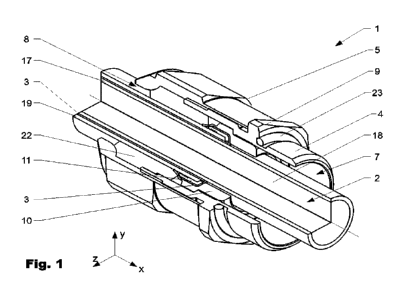
Figure 1 to figure 2 show a variant of a holding device 1 according to the
disclosure in
an assembled state on a cable 2. The cable 2 comprises a conductor 3.8 having
a braid 3
surrounding the latter, in particular a shielded braid. An intermediate
insulation 17 is
arranged between the braid 3 and the conductor 18. The braid 3 is surrounded
from the
outside by a cable sheath 19. Other types of cables and constructions are
however
likewise possible. The cable sheath 3.9 is removed in the region of the
holding device 3.,
and an end of the braid 3 is exposed.
The holding device 1 comprises a base element 4 and a tensioning element 5
which can
be interconnected to the latter. The base element 4 serves for mounting the
holding
device i.e.g. at a housing, or similar (not shown). Therefore, said base
element 4 has a
base 9 having a bearing face for bearing on the housing. A seal 23 for sealing
the holding
device i. in relation to the housing can be arranged on the base 9. In the
case shown, the
tensioning element 5 is a clamping nut, but other embodiments of the
tensioning
element are also conceivable. The base element 4 has a first opening 7 which
extends
in an axial direction for the passage of the cable 2, while the tensioning
element 5 has a
second opening 8 which extends in the axial direction for the passage of the
cable 2.
The tensioning element 5 serves, inter alia, for clamping a clamping element
22,
arranged between the base element 4 and the tensioning element 5, and for
holding
the cable 2 and optionally sealing the latter. The clamping element 22 is
advantageously made from a deformable material. Moreover, a crimp element 6 is
CA 03165195 2022- 7- 18
14
arranged between the base element 4 and the tensioning element 5. The crimp
element
6 in the axial direction is arranged between the clamping element 22 and the
base
element 4. Moreover, a contact spring 20 is arranged in the radial direction
in the base
element 4, said contact spring 20 being arranged in a groove 21 that radially
encircles
the first opening 7. The contact spring 20 ensures improved electrical contact
between
the crimp element 6 and the base element 4.
The crimp element 6 comprises an outer crimp sleeve io and an inner support
sleeve ii
which is arranged in the latter and is advantageously axially deformable. The
cable 2
having the crimp element 6 is shown in figure 3. In the lower part of the
image, the non-
deformed crimp sleeve io is shown (prior to crimping). In the upper part of
the figure,
the deformed crimp sleeve io is shown (after crimping). In both states, the
braid 3 is
arranged between the crimp sleeve io and the support sleeve ii. After
crimping, the
crimp element 6 is advantageously fixedly connected to the cable 2. The
deformed
crimping region 12 can fit snugly about the support sleeve 11 and in regions
about the
cable 2. An embossing 25 as a result of crimping, or of the crimping tool,
respectively,
can be arranged on an outer side of the crimp sleeve io, for example on the
crimping
region 12. Prior to crimping, the deformable crimping region 12 extends in the
axial
direction. The crimping region 12, in the assembled state of the support
sleeve ii in the
crimp sleeve io, in the axial direction then projects beyond said support
sleeve ii. (cf.
lower part of the figure). In the variant shown, a length C, defined from the
end of the
(non-deformed) crimping region 12 in the axial direction up to a folding edge
of the
braid, has a ratio of C/D = 0.3-0.5 in relation to an outer diameter D of a
contact surface
26 of the crimp sleeve io (see figure 2). The contact surface 26 serves for
applying the
axial contact pressure force about the crimp sleeve io and the support sleeve
ii. for
CA 03165195 2022- 7- 18
15
crimping. For crimping, the crimp sleeve i.o on the outer side has an
encircling
protrusion 24. The latter, in the assembled state, in the axial direction
bears on the stop
14 of the base element 4.
It is furthermore possible that the support sleeve 11 has at least one
deformation region
15 for the axial deformation. In the case shown, the support sleeve la on its
internal side
that faces the cable 2 has a plurality of grooves, which in the case of an
axial
deformation can serve as strain relief grooves and/or crushing grooves. It can
be seen,
in the deformed state as well as the non-deformed state, that the support
sleeve 11 has
a radial shoulder 3.6 for resting on an end of the cable sheath 19.
Furthermore, the crimp
sleeve 10 in the axial direction comprises a stop 14 for the support sleeve
11. In this way,
the support sleeve 11, and by way of the latter the crimp sleeve lo, can be
easily and
rapidly positioned on the cable 2. It is furthermore advantageous for the
crimp sleeve
lo to have at least one radial through opening 13 such that the intervening
braid 3 can
be visually identified in the assembled state through said through opening 13.
In the
deformed state, the support sleeve 11 is enclosed and held by the crimp sleeve
lo and
the cable 2.
In order for the holding device 1 shown to be assembled, the braid of the
cable 2 below
the cable sheath 19 can first be exposed. The tensioning element 5 can then be
threaded onto the cable 2, followed bythe clamping element 22 and the support
sleeve
11. The support sleeve 11 by way of the radial shoulder 3.6 can be pushed up
to an end
of the cable sheath 3.9 and positioned there. The braid 3 of the cable 2 is
subsequently
flared and is placed about the support sleeve 11. Any projecting braid 3 can
be severed.
Thereafter, the crimp sleeve io is pushed onto the cable 2 and over the
support sleeve
CA 03165195 2022- 7- 18
1.6
it The braid 3 can then be axially crimped between the crimp sleeve i.o and
the support
sleeve 3.3.. After this step, the base element 4 is pushed onto the cable 2
and
interconnected to the tensioning element 5.
CA 03165195 2022- 7- 18
17
LIST OF REFERENCE SIGNS
1 Holding device 14 Stop
2 Cable 15 Deformation
region
3 Braid 3.6 Radial shoulder
4 Base element 17 Intermediate
insulation
Tensioning element 18 Conductor
6 Crimp element 19 Cable sheath
7 First opening 20 Contact spring
8 Second opening 21 Groove
9 Base 22 Clamping
element
io Crimp sleeve 23 Seal
11 Support sleeve 24 Protrusion
12 Crimping region 25 Embossing
13 Through opening 26 Contact
pressure face
CA 03165195 2022- 7- 18