Note: Descriptions are shown in the official language in which they were submitted.
CA 03165314 2022-06-17
WO 2021/144778
PCT/IB2021/050359
1
Injection Needle with Endoscope for Regenerative Medicine
BACKGROUND
[0001] This application is a nonprovisional of U.S. Provisional application
62/962,987 filed January 18, 2020, incorporated by reference.
[0002] This application relates to endoscopes and injection needles, or
processes
specially adapted or intended to be used for evaluating, examining, or
treating human or
animal bodies for medical purposes.
[0003] In medical treatments by injection of stem cells, platelet enriched
plasma
treatments, exosomes, and similar biologicals, it is known to position an
injection needle
based on ultrasound and the physician's knowledge of human anatomy, and inject
the
biological into the general region of the pathology. The injected biological
then marshals the
body's own healing systems to repair the pathology.
SUMMARY
[0004] In general, in a first aspect, the invention features an injection
needle. The
needle has a point designed to pierce flesh of a living body, and has a fluid
passage
therethrough designed for delivery of a therapeutic agent at a delivery site
within the body,
the delivery site to be reached by piercing at which an injection fluid is to
be delivered via the
fluid passage. The outer diameter of the needle is no more than about 2.1mm.
Solid state
illumination circuitry and an imaging sensor are designed to provide
illumination and
imaging, and are mounted within supporting structure designed to support the
illumination
circuitry and imaging sensor within the needle arranged for illuminating and
viewing the
delivery site reached by piercing.
[0005] In general, in a second aspect, the invention features a method. A
patient is
pierced with a needle. The needle has a point designed to pierce flesh of a
living body, and
having a fluid passage therethrough designed for delivery of a therapeutic
agent at a delivery
site within the body, the delivery site to be reached by piercing is a site at
which an injection
fluid is to be delivered via the fluid passage, the outer diameter of the
needle being no more
than about 2.1mm. The needle surrounds solid state illumination circuitry and
an imaging
sensor designed to provide illumination and imaging, mounted within supporting
structure
CA 03165314 2022-06-17
WO 2021/144778
PCT/IB2021/050359
2
designed to support the illumination circuitry and imaging sensor within the
needle arranged
for illuminating and viewing flesh ahead of the point of the needle during the
piercing. When
the point of the needle reaches the delivery site, insufflation fluid is
passed through a passage
of the needle to inflate a cavity at the delivery site. The supporting
structure is extended
forward through the needle, sufficiently to create a field of view for the
imaging sensor wider
than the field of view available during the piercing. The imaging sensor and
illumination
circuitry are rotated around a longitudinal axis of the needle, a rotation or
orientation sensor
rotationally affixed to the imaging sensor being designed to produce a signal
that encodes
angular rotation of the image sensor. The video from the image sensor and the
encoded
angular rotation signal are processed together in image-righting circuitry to
compute a
corrected video signal that corrects the video signal for rotation to present
a video signal
consistently oriented relative to a frame of reference of a user of the
injection needle.
[0006] Embodiments of the invention may include one or more of the following
features. These features may be used singly, or in combination with each
other. The image
sensor may have an axis of view offset from the axis of the needle. The image
sensor may be
mounted within the supporting structure with its axis of view offset from the
axis of the
needle. The image sensor may be mounted within the supporting structure with
the camera's
axis of view parallel to the axis of the needle. A lens may be designed and
mounted within
the supporting structure to refract an image received by the image sensor off
the axis of the
needle. The angle of offset may desirably be between about 25 and about 350,
or between
about 65 and about 75 . Two or more supporting structures may be designed to
support
imaging sensors so as to provide different angles of offset for the imaging
sensors' fields of
view relative to the axis of the needle. A rotation or orientation sensor may
be designed to
produce a signal that encodes angular rotation of the image sensor. Circuitry
may be
designed to receive the encoded angular rotation signal and a video signal
from the image
sensor, and to compute a corrected video signal that corrects the video signal
for rotation to
present a video signal consistently oriented relative to a frame of reference
of a user of the
injection needle. Wireless transmission circuitry may be designed to transmit
video signal
from the imaging sensor to a display monitor without transmission wires
connected to the
injection needle. One or more reservoirs may be designed ot hold insufflation
fluid.
Controles may be designed to administer the fluid without fluid tubes flowing
externally to
CA 03165314 2022-06-17
WO 2021/144778
PCT/IB2021/050359
3
the injection needle. A piercing point distal from the imaging sensor may be
designed to
pierce flesh and to simultaneously provide protection to the imaging sensor
from the flesh
and its fluids, and to allow an image of the flesh to reach the imaging
sensor. The outer
diameter of the needle may desirably be no more than about 1.66mm, no more
than about
1.28mm, no more than about 0.91mm, no more than about 0.82mm. A proximal
portion of a
handle may have electronics for drive of the illumination circuitry and to
receive imaging
signal from the imaging circuitry, the proximal handle portion being designed
to permit
sterilization between uses. A joint between the proximal handle portion and
the needle and
supporting structure may be designed to separably connect the needle and
supporting
structure to the proximal handle portion. The joint may permit removal of the
supporting
structure for disposal and replacement. The joint, when connected, may be
designed to
provide mechanical force transfer between a surgeon's hand to the needle, and
electrical
connectivity between the proximal handle circuitry and the illumination
circuitry and imaging
sensor. The supporting structure may be slideable within the needle to permit
the imaging
stricture to be retracted behind the point during the piercing, and to be
extended beyond the
point to obtain a wider field of view. The patient may be human or animal.
[0007] The above advantages and features are of representative embodiments
only,
and are presented only to assist in understanding the invention. It should be
understood that
they are not to be considered limitations on the invention as defined by the
claims.
Additional features and advantages of embodiments of the invention will become
apparent in
the following description, from the drawings, and from the claims.
DESCRIPTION OF THE DRAWINGS
[0008] FIGS. 1A, 1C, 2A. 2B, 3B, 3C, 4A. and 4B are perspective views
partially cut
away.
[0009] FIGS. 1B and 3A, are plan sectional views.
DESCRIPTION
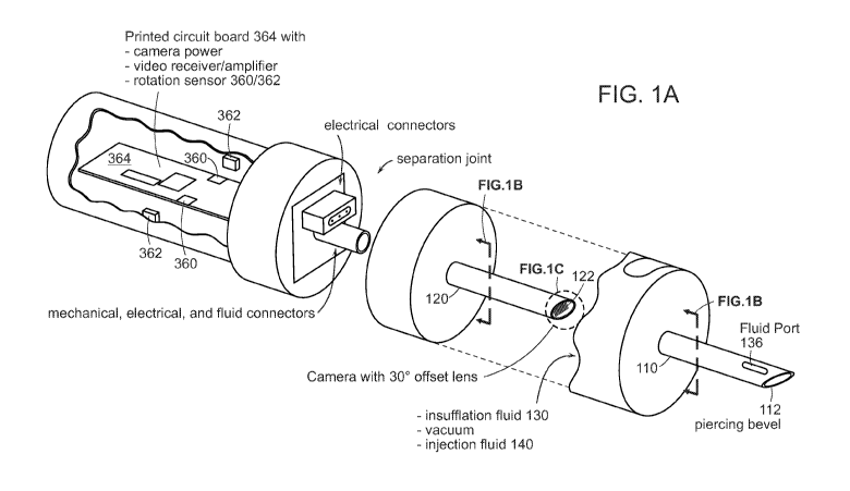
I. Overview
[0010] Referring to FIGS. lA and 1B, in regenerative medicine, a suspension of
some
orthobiologic agent, such as stem cells, exosomes, platelet enriched plasma,
BMAC (bone
CA 03165314 2022-06-17
WO 2021/144778
PCT/IB2021/050359
4
marrow aspirate concentrate), anti-inflammatory factors, or similar biologic
component, is
injected into a body at the site of a lesion or pathology to be treated. The
higher the number
of cells, components, etc. that can be placed on target, the higher the
likelihood of success.
Therefore, an injectable agent may be prepared by concentrating the cells,
exosomes, etc. to a
high concentration, which may be administered by needle/scope 100 that is
designed to allow
precise placement. An injection needle 110 with a piercing point 112 may be
combined with
an endoscope 120, or otherwise fitted with an image sensor 122, to allow
injection
needle/scope 100 to be guided precisely to the pathology, to increase the
concentration of the
injected biologic agent at the precise site.
[0011] Among the advantages that may be realized are the following. The
techniques
and apparatus may be useful for cartilage resurfacing, placement of stem cells
to regenerate
some tissue (such as pancreas or liver cells), foster bone or marrow
regeneration, and the like.
The technique and apparatus may improve a physician's ability to deliver
biologic agents at
the site of pathology. This may allow for a greater concentration of proteins
(biologic or
.. synthetic) to be delivered at the pathological site. The higher
concentration of proteins may
modulate and block inflammation, and deliver growth and healing factors to the
site. More-
precise delivery may reduce pain by blocking inflammation and reducing the
distension/disruption of tissue caused by larger injection deliveries, his, in
turn, may permit
reduction in use of opioids, by an estimated 70%. More-precise delivery may
permit delivery
of proteins that can promote faster and more organized healing. In addition,
greater signaling
via exosomes may be sent to cells (induction), to obtain a longer therapeutic
effect. The
technique and apparatus, especially the small size and minimization of tissue
damage, may
reduce injury and improve healing, which may allow more procedures to be done
as
orthobiologic injection in the physician's office, rather than a surgical
center, which may
reduce costs. The needle tip 112, 122 may be designed to provide standard
placement and
provide a good field of view, via rotation about its roll axis, which may
reduce tissue damage
and pain to the patient. Various techniques for enhancing view through
rotation are discussed
in section IV below.
CA 03165314 2022-06-17
WO 2021/144778
PCT/IB2021/050359
Preparation and administration of biologic agents
[0012] A typical injection of a biologic begins with a draw from the patient,
to
prepare an autologous injection. For example, a typical blood draw from a
patient of 5-6 cc
has about 5 million stem cells, approximately 900,000 stem cells per cc Those
stem cells
5 may be concentrated by centrifuging or other separation means.
[0013] Referring to FIGS. lA and 1B, administration of the concentrated
biologic
may be by means of injection needle/scope 100 designed to permit precise
placement.
Camera 122 may be mounted in endoscope shaft 120, and camera shaft 120
inserted through
cannula 110. Cannula 110 and camera 122 may be inserted into a patient. Camera
122 may
be retracted within cannula 110 during the piercing phase of the injection, so
that cannula tip
112 does the cutting, and camera 122 is protected. When used to inject into a
joint, cannula
tip 112 cuts an injection pathway until the capsule around the joint is
pierced. In some cases,
needle 110 may contain a rigid support element during the piercing to provide
strength and
rigidity, and then this rigid support element may be withdrawn and replaced by
camera 122
and camera shaft 120 when the needle is placed approximately, so that camera
122 may be
used to guide the needle to a precise delivery site. Camera shaft 120 may then
be advanced
to extend slightly beyond the tip of the cannula, to allow camera 122 an
unobstructed view,
and to reduce risk that the sharp tip 112 of the cannula will injure cartilage
within the joint.
Gas 130 (typically carbon dioxide) may be used to insufflate the field of view
for camera
.. 122, to blow blood and other debris off the camera lens or window 124, and
to dry the area to
improve view and to decrease flow and improve the localization of the
injectate. Likewise,
water 130 may be injected into the site for insufflation/expansion of the
joint, and for
cleaning of window 124. The insufflation fluid (liquid or gas) 130 may pass
through an
annulus 132 between the outer diameter of camera shaft 120 and inner diameter
of cannula
110 if camera shaft 120 is slightly smaller than the inner diameter of cannula
110, or camera
shaft 120 may have a "dimple" of a channel in its outer edge that carries
insufflation fluid
130. Cannula 110 may have ports 136 somewhat proximal of the tip, to reduce
image
blurring that might be caused by insufflation delivery closer to camera 122.
If camera shaft
120 has a groove 134 for passage of insufflation fluid 130, that passage may
spiral around the
shaft, or it may branch into several circumferential channels, so that the
insufflation channel
134 will always line up with insufflation ports 136. Camera 122 may guide the
injection
surgeon to the site of the pathology. At the site of the pathology, gas 130
may be blown to
CA 03165314 2022-06-17
WO 2021/144778
PCT/IB2021/050359
6
create a volume to improve visibility, and to dry the site. Camera shaft 120
may be
withdrawn, leaving the cannula tip 112 at the site of the pathology.
Alternatively, camera
shaft 120 may have a lumen through which the injectable biologic 140 or other
fluid may be
delivered to the desired site, or may provide a passage/groove between camera
shaft 120 and
cannula for conduct of fluids. To the degree that blown gas 130 is not drawn
off by
withdrawal of camera 122, and does not escape on its own, further gas 130 may
be removed
by vacuum. Then concentrated biologic or other injectable fluid 140 may be
injected through
the cannula 110.
III. Injection scope
[0014] Referring to FIGS. 2A and 2B, needle/scope 100 may incorporate
functions of
an endoscope and injection needle (with its penetrating tip and fluid
passages), integrating
camera shaft 120, piercing cannula 110, 112, insufflation passage 134, and
delivery needle
(or any two or three of these functions) into a single integrated device. The
cannula/needle
110 may have a piercing point 112, and camera 122 may be recessed behind that
point. The
needle may have a channel that can pass the biologic concentrate while camera
122 remains
at the site where the injection is to be delivered. Wires may supply power to
and receive
video signal from camera 122.
[0015] Needle/scope 100 may be formed around a hollow metal shaft 110. At or
near
the tip may be an imaging camera 122. The tip 212 of the needle may be formed
from a clear
material in a roughly conical shape. Tip 212 may be sharpened to provide a
cutting/penetrating tip 214. Rearwards of the cutting tip 214 may be LEDs 250
to provide
illumination. Alternatively, an illuminating LED may be somewhat rearward, and
light may
be conveyed from the LED to the front 250 of the device through light fibers
252. A tube
242 for carrying injectable fluid 140 may end at an exit aperture 244 near the
tip. Likewise, a
tube for carrying insufflation and cleaning gas (which may be the same as the
tube for
injectable fluid, or different) may end at an exit aperture near the tip.
[0016] The needle may be of diameter of an injection needle, such as less than
2.1mm
(14 gauge), 1.6 mm (16 gauge), 1.47 mm (17 gauge), 1.27 mm (18 gauge), 1.07 mm
(19
gauge), or 0.91mm (20 gauge).
CA 03165314 2022-06-17
WO 2021/144778
PCT/IB2021/050359
7
Wall
Needle Needle
Gauge Thickness
O.D. (mm) I.D. (mm)
(mm)
22 gauge 0.718 0.413 0.152
21 gauge 0.819 0.514 0.152
20 gauge 0.908 0.603 0.152
18 gauge 1.27 0.838 0.216
16 gauge 1.651 1.194 0.229
14 gauge 2.109 1.6 0.254
Smaller diameters may reduce pain. Smaller diameters may be especially
important in
arthroscopic surgery, where the working area between bones is confined,
between hard
structures such as bone and cartilage. An image sensor 122 that is lmm x lmm
has a
diagonal dimension of 1.4mm, leaving sufficient gaps around the four edges for
fluid
passages 134, 142. With the thickness of the walls of an injection needle, the
outer diameter
may end up at about 1.65 mm, about the same size as a 16 gauge needle.
[0017] Referring to FIG. 3A, one suitable camera is the OmniVision 0V6946, a
400x400 image sensor, 714x707 tim, in a package whose external dimensions are
950x940
tim. As smaller cameras become available, the size of the needle may be
reduced as well.
The field of view of the 0V6946 is about 140 . A lens 226 may be placed in
front of camera
122 to offset that field of view by 30 off the central axis. Camera 122
and/or lens 226 may
be adjustable so that the offset may be varied, for example, between 0 to 30
, or 30 to 70 .
[0018] In some cases, the injection scope may have a passage for inflation by
gas or
saline 130. Carbon dioxide may be especially desirable as an inflation medium,
because of
its optical properties, it and it may create a dry environment to confine any
tendency of the
aqueous biologic agent to flow away. Carbon dioxide, nitric oxide, or another
gas may be
blown across the front of objective lens 124 of the scope for cleaning, and to
blow away
smoke and debris created by other instruments. The passage for insufflation
gas 134 may be
the same as the channel for passage of injection fluid 142, or may be
separate.
IV. Increasing available view through rotation of needle/scope 100
[0019] In manipulating the delivery needle/cannula, it may be desirable to
minimize
off-axis movement. Forward piercing thrust on a single line is a necessary
evil in any
injection, but it is desirable to minimize sweep back-and-forth movement, or
pitch/yaw
bending/rotation. Only roll motion, rotation around the axis, is
nondestructive to surrounding
CA 03165314 2022-06-17
WO 2021/144778
PCT/IB2021/050359
8
tissue. Several techniques may be used to enhance the available view through
rotation, to
reduce the surgeon's need for other, more-destructive motions.
IV.A. Angular offset of image lens 226
[0020] Referring to FIGS. 2B, 3A, 3B, camera 122 of the injection scope may
have a
lens 226, or may be mounted within needle/scope 100, to provide a view that is
offset relative
to the longitudinal axis, for example, by 200, 25 , 300, 350, 40 , 45 , 60 ,
or 70 . By
offsetting the angle of view, the scope may be rotated on-axis to cover
greater total field of
view.
[0021] Referring to FIG. 3B, camera 122 may have a cone of view of 140 , 70
off-
center in each direction, subtending a portion of the full 360 view. If
camera 122 is placed
at a 30 offset within the scope, or its view is refracted 226 by 30 , then a
forward cone of
view of 80 is visible from any orientation. By rotating needle/scope 100 on-
axis (the roll
axis), then the forward 200 is visible. A 30 offset, plus rotation of the
scope may more than
double the available field of view.
IV.B. Image righting
[0022] Referring to FIG. 3C, proximal handle may include rotational sensors
360 so
that an angular orientation of camera 122 may be ascertained. For example, the
inner surface
of proximal handle may mount one or more magnets 362, and printed circuit
board 364
(which rotates with rotation collar 460 and disposable portion 470) may have
Hall effect
sensors 360 that detect the magnets. Alternatively, the handle may have a
level, gravitometer
or other sensor that detects orientation. This may be used to compute a
rotational orientation,
which may in turn be used to "right" the image from camera 122 on a video
display screen.
For example, the image may be rotated for display so that the display from a
camera that is
being rotated behaves similarly to the image in a rod-lens scope, where the
image remains
rotationally stationary as the scope is rotated. Unless the orientation of an
image displayed
on a graphical user interface is first corrected, the displayed image may be
disorienting to the
user. By defining a direction according to the user's point of view, the image
processing unit
may use data from the rotational sensors to automatically rotate images so
that images
correspond with the user's point of view. This assists the surgeon in
maintaining spatial
awareness and making fine motion without injuring the patient.
CA 03165314 2022-06-17
WO 2021/144778
PCT/IB2021/050359
9
[0023] In some cases, image processing unit may also correct for the effects
of lens
distortion.
IV.C. Reducing tethering by wireless connection
[0024] The injection scope may be cordless/tetherless to improve a surgeon's
ability
to maneuver the injection scope. The injection scope may communicate image
information to
a base station imaging unit via a wireless connection, such as WiFi or
Bluetooth. The image
may be displayed on a display screen in the surgeon's field of view, driven by
an image
processing and control computer. Injection scope 100 may have a battery to
supply power.
The injectable fluid, typically 3 to 6 ccs, may be stored in a small
reservoir. If insufflation
130 is by means of carbon dioxide, carbon dioxide may be supplied in a
cartridge, for
example a medical version of a conventional CO2 cartridge. 30 to 60ccs of
insufflation water
or saline may be stored in an on board reservoir.
[0025] Reducing tethers may improve the surgeon's ability to rotate
needle/scope
100, and may improve sterility by reducing cable flop and contact between
nonsterile cables
and the patient.
IV.D. Reducing torque mass by reducing rotational moment
[0026] Referring to FIG. 4A, the body of the injection scope may have a
rotation joint
462 so that needle/scope 100 (with its camera at the tip) may be rotated,
while the main body
of the injection scope remains stationary. Any cords or hoses for power or
fluids may be
attached to the stationary part of the injection scope, to ease rotation.
[0027] It may be desirable to put as much of the mass of the battery, fluid
reservoirs,
and any remaining tethers in the stationary part of the scope. Of the mass
that must rotate, it
may be desirable to concentrate that mass on the axis of needle/scope 100, to
reduce the
rotational moment and "flopping" of any remaining cords.
V. Disposable camera shaft
V.A. Overview
[0028] Referring to FIG. 4A and 4B, needle/scope 100 may be structured to
permit
detachment of a needle/shaft/scope portion 110, 120, 470 from the
needle/scope's handle
472. A camera or image sensor 122 at the tip of shaft 110, any panning
mechanism,
illumination, power and signal connectors, and fluid flow channels may be in
the disposable
CA 03165314 2022-06-17
WO 2021/144778
PCT/IB2021/050359
shaft 470. Handle 472 may be designed to be reusable (which implies that
handle 472 may
be sterilizeable, for example in an autoclave or other sterilization device,
or protectable by a
disposable sterility sleeve). Joint 474 between the detachable shaft 470 and
the reusable parts
of handle 472 may be generally distal within the handle (but not necessarily
at the distal-most
5 end). The replaceable shaft portion 110, 120, 470 may be disposable,
along with a disposable
portion of the handle that is disposable with shaft.
[0029] The disposable cap, as this distal-most portion of the handle, may
serve as a
mounting base for shafts 110, 120, and may disconnect from the remainder 472
of the handle.
This disposable cap portion 470 (along with shafts 110, 120 and componentry
inside) may be
10 disposable.
[0030] Rotation collar 460 may have surface features to allow a surgeon to
rotate the
rotation collar 460 about the central axis of the handle, that is, about the
roll axis of shafts
110, 120. During the injection procedure, insertion shaft 110, 120, disposable
cap 470 and
rotation collar 460 may be locked to rotate with each other, so that rotating
rotation collar 460
effects rotation of the disposable cap 470 and shafts 110, 120.
[0031] Proximal stationary handle has a shell surrounding componentry within
the
handle. The outer diameter and outer surface of the handle may be designed to
provide an
easy and low-slip grip for a surgeon's hand. Joint 462 between the proximal
handle and
rotation collar may allow these two components to rotate relative to each
other. In some
cases, a circuit board and similar componentry inside proximal handle 472 may
rotate with
disposable cap 110, 120, 470 and rotation collar 460, inside proximal handle.
[0032] Disposable cap 110, 120, 470 and rotation collar 460 may be separable
from
each other at separation joint 474, so that disposable cap and shafts 110,
120, 470 may be
disposable, while handle 472 and rotation collar 460 (and componentry inside
them) are
reusable.
[0033] At separation joint 474 between disposable portions 110, 120, 470 and
the
reusable portions 472 including rotation collar 472, three basic connections
may be made:
= A rotation-locking coupling to hold the disposable portion 470 to the
reusable portion
472. This coupling may have sufficient strength to transmit insertion and
withdrawal
forces, roll, pitch, and yaw torques, lateral forces, and similar forces from
the
proximal reusable handle 472 to the distal disposable portion 110, 120, 470,
thereby
CA 03165314 2022-06-17
WO 2021/144778
PCT/IB2021/050359
11
to allow a physician to aim the illumination and/or camera as needed.
Separation
joint 474 between disposable portion 110, 120, 470 may lie generally toward
the
distal end of the handle. Disposable portion 110, 120, 470may engage through
flat
force-transmittal surfaces at the center of joint 474 and around the
circumferences, so
that these forces are supported around the circumference of separable joint
474. One
or more release buttons 146 may be pressed or squeezed to cause one or more
locking
snaps 148 to disengage. The mechanical connection may include a rotatable
locking
ring or other release/fixation mechanisms.
= An electrical connection to supply power to the illumination source and
camera, and
to carry optical signals back from camera 122 to the processing board 364 in
handle
and display system outside needle/scope 100. The disconnectable electrical
connections for power and signal may be effected by a USB-C connector mini
HDMI
connector, or similar connector that can maintain signal integrity for high
speed
signals. If illumination is conveyed by optical fiber, joint 474 may include
an optical
connector.
= A disconnectable connection to any panning mechanism for camera 122 may
be
effected by a physical connector, such as a linkage.
[0034] One or more fluid hoses for injectable liquid or inflation gas (or two
hoses,
one for the injectable fluid and one for gas) may enter through disposable
cap, so that the
entire set of fluid tubing for the irrigation/inflation channel may be
disposable with the
disposable shaft portion. In other cases, a fluid hose may enter the proximal
end of the scope,
and disconnectable fluid connections within joint for fluid inflow and outflow
may be
effected by gaskets, 0 rings, and the like. Alternatively, connectors for the
hoses may be
outboard of needle/scope 100 itself, either near needle/scope 100 (for
applications where it
may be desirable to allow "quick change" replacement of the insertion shaft in
the course of a
single procedure), or far from needle/scope 100, typically at the receptacle
for waste fluid, to
ease disposal of all hoses that are potentially contaminated by contact with
the patient.
[0035] Disposable portion 110, 120, 470 may be designed to facilitate
disposability of
components that come into contact with bodily fluids. Because sterilization is
often
imperfect, patient safety may be improved by disposing of components that have
come into
contact with patient bodily fluids. To improve sterilizability, it may
desirable to reduce
CA 03165314 2022-06-17
WO 2021/144778
PCT/IB2021/050359
12
componentry in the disposable component 110, 120 so that cost of the
disposable component
may be reduced, and to reduce surface features and crevices that may be
difficult to sterilize.
Thus, the lens, image sensor 122, illumination LED 250, panning mechanism, and
shaft may
be disposable. In addition, because shafts 110, 120 are used for fluid inflow
and outflow, and
are disposable, sealing against bodily fluids may be unnecessary.
[0036] Various replaceable components 110, 120, 470 may have different
instruments
at their tip. For example, various replaceable shafts may have cameras
oriented at 0 (directly
on-axis), 30 , 45 , 70 , and 90 .
[0037] Further features of a partially disposable, partially reusable device
are
described in U.S. Pub. No. 2019/0374095 Al, incorporated by reference
[0038] Shaft 110 may also carry power wires to the illumination LED and the
camera,
and carry signal wires that carry an optical signal back from the camera to
electronics in the
reusable portion 472 of the handle. Electrical power to the camera may be
supplied over
conductors in a flexible cable or on a printed circuit board (flexible or
rigid), and insulated
with a conformal and insulating coating such as parylene. This same flexible
circuit board
may have signal conductors for the video signal from the camera. The video
signal may be
transmitted from the camera to the handle using any video signal protocol, for
example, MIPI
(Mobile Industry Processor Interface) or HDMI. Parylene may also improve
biocompatibility.
[0039] Shaft 120 may also carry cables or other mechanical elements to control
panning of the camera.
[0040] Referring to FIG. 4A and 4B, rotation collar may have various features
that
make rotation easy. For example, depressions may provide a good grip for
fingers for light
roll torque. A fin may provide greater leverage for greater roll torque, and
may also provide
a fixed rotational point of reference.
[0041] If camera 122 is pannable or has other controllable features, there may
be a
control (for example, a lever, or a touch-slide panel, etc.) on the handle to
control that
adjustment of the camera.
[0042] Electrical connectors such as USB-C or mini-HDMI connectors may be used
to connect the camera to a circuit board interior to the handle.
CA 03165314 2022-06-17
WO 2021/144778
PCT/IB2021/050359
13
[0043] Rotation-locking coupling may lock disposable cap in rotational
relationship
to rotation collar. Various rigid and resilient features may lock them
together for other forces
and torques, and release buttons may permit them to disengage to allow
replacement of
disposable cap.
[0044] The reusable portion 472 may contain a number of components, typically
components that have only incidental patient contact (and therefore present
less risk of cross-
infection), are higher in cost (and therefore desirably reusable), and either
sterilizeable or
may be covered by a sterility sleeve. For example, reusable portion 472 may
hold power
transformers, signal amplifiers, controls for the illumination LED and camera,
a mechanical
control for panning the camera, rotation sensors for righting of an image from
the camera,
and the like. The handle may also include connections to external sources and
destinations of
power, signal, fluid, and the like.
[0045] For clarity of explanation, the above description has focused on a
representative sample of all possible embodiments, a sample that teaches the
principles of the
invention and conveys the best mode contemplated for carrying it out. The
invention is not
limited to the described embodiments. Well known features may not have been
described in
detail to avoid unnecessarily obscuring the principles relevant to the claimed
invention.
Throughout this application and its associated file history, when the term
"invention" is used,
it refers to the entire collection of ideas and principles described; in
contrast, the formal
definition of the exclusive protected property right is set forth in the
claims, which
exclusively control. The description has not attempted to exhaustively
enumerate all possible
variations. Other undescribed variations or modifications may be possible.
Where multiple
alternative embodiments are described, in many cases it will be possible to
combine elements
of different embodiments, or to combine elements of the embodiments described
here with
other modifications or variations that are not expressly described. A list of
items does not
imply that any or all of the items are mutually exclusive, nor that any or all
of the items are
comprehensive of any category, unless expressly specified otherwise. In many
cases, one
feature or group of features may be used separately from the entire apparatus
or methods
described. Many of those undescribed alternatives, variations, modifications,
and equivalents
are within the literal scope of the following claims, and others are
equivalent. The claims
may be practiced without some or all of the specific details described in the
specification. In
CA 03165314 2022-06-17
WO 2021/144778
PCT/IB2021/050359
14
many cases, method steps described in this specification can be performed in
different orders
than that presented in this specification, or in parallel rather than
sequentially, or in different
computers of a computer network, rather than all on a single computer.