Note: Descriptions are shown in the official language in which they were submitted.
WO 2021/148285
PCT/EP2021/050570
Process of manufacturing hollow spherical glass particles
The present invention relates to a process for the preparation of hollow
spherical glass
particles comprising at least SiO2, A1203, and an alkali metal oxide, wherein
the process
comprises the preparation of precursor-particles comprising at least SiO2,
A1203, and an
alkali metal oxide by mixing the starting materials, slurrying the starting
materials with water
followed by spray drying and heat-treating the precursor-particles at a
temperature from
1000 C to 1800 C, preferably from 1300 C to 1600 C by contacting the precursor-
particles
thus obtained with at least one naked flame.
Hollow spherical glass particles, also known as hollow glass microspheres, are
used as fillers
for materials in various fields of application. The specific gravity of such
hollow spherical
glass particles is significantly lower as compared with other fillers while
the physical
properties such as heat resistance, pressure resistance and impact resistance
remain on a
high level. Therefore, hollow spherical glass particles are widely used
fillers for weight-
reduced articles containing molded resin or metal components, e.g. automotive
parts,
household articles, sealing materials or construction materials. Examples of
such hollow
spherical glass particles and their manufacture have been described for
example in US
3,699,050, US 4,336,338, US 5,176,732, and US 2002/0004111 Al.
The methods known in the art for producing hollow spherical glass particles
usually involve
the dispersion of a fine glass powder in a hot gas of high temperature,
wherein the glass is
heated to a melt so that the viscosity of the molten material (starting from
the outer layer)
decreases. Simultaneously, a gas is formed by vaporization of an expansion
agent present in
the composition of the precursor-particles. Accordingly, due to the surface
tension, the shape
of the resulting particles will be spherical and at the same time, the
particles will be hollow
due to the gas formed within the particles.
Regarding the chemical composition of the hollow spherical glass particles,
borosilicate glass
is widely used due to its chemical and mechanical resistance. For instance, JP-
A-58-156551
discloses a process for forming hollow borosilicate glass microspheres from
starting
materials such as SiO2, H3B03, CaCO3, Na2CO3, N1-141-12PO4 and Na2SO4.
However, due to
regulatory requirements, the application of boron-free hollow aspherical glass
particles is
preferred. Furthermore, boron may make the particles brittle.
WO 2017/108831 Al discloses a method for the preparation of boron-free hollow
spherical
alumosilicate glass particles using A1203, SiO2 and at least one alkali metal
oxide as starting
materials by mixing the starting materials with water and spray drying the
mixture, thereby
obtaining precursor-particles having an average particle size from 80 pm to
400 pm and a
residual moisture from 1 % to 10 %, and feeding the precursor particles into a
heating device
in a temperature range from 1500 C to 1800 C, such that the dried mixture
falls through the
heating device for about 1 s to about 10 s, thereby yielding hollow spherical
glass particles
CA 03165336 2022- 7- 19
WO 2021/148285
PCT/EP2021/050570
2
which preferably have a particle size from 10 pm to 600 pm. The heating device
is a tube
furnace comprising an outer heating mantle.
Our older application WO 2020/020921 Al discloses a boron-free hollow
spherical glass
particle comprising at least 30 wt.-% of A1203, at least 35 wt.-% of SiO2 and
at least 18 wt.-%
of at least one alkali metal oxide and having a particle diameter in the range
from more than
20 pm to 75 pm. The application furthermore discloses a method of
manufacturing such
particles by providing a composition comprising at least 30 wt.-% of A1203, at
least 35 wt.-%
of SiO2 and at least 18 wt.-% of at least one alkali metal oxide, wherein the
components are
present as fine particles having a particle size of 10 pm, mixing the
particles with water and
optionally an organic binder, spray drying the particles and feeding the dried
particles into a
heating device, for example a tube furnace, such that the particles are blown
upwards while
the temperature is maintained above 1000 C, thereby obtaining hollow spherical
glass
particles. Alternatively, two heating devices connected in series may be used
or at least a
part of the particles is cycled back into the heating device. The tube
furnaces described
comprise an outer heating mantle.
JP-A-7-277768 discloses a method for manufacturing hollow glass spheres. As
starting
material a mixture of a glass powder and an inorganic material, preferably a
carbonate or a
sulfate powder which decomposes at higher temperatures thereby generating a
gas is used.
The mixture is converted to granules, for example by means of a spray dryer
and the
granules are thereafter supplied into an air stream of a temperature
sufficient to decompose
the inorganic material to generate a gas. Preferably, the heat treatment is
carried out for 5 to
1000 ms in an air steam of about 1200 to 1600 C. In example 1, a glass powder
(55% of
SiO2, 14% of A1203, 8% of B203, 1% of MgO, 21% of CaO and 1% of BaO; wt.-
percentages)
is mixed wth CaSO4* 2 H20 and water to obtain a slurry which was spray dried
to obtain
granules with an average particle size of 50 pm. Thereafter, the granules were
supplied into
a gas burner air stream having a maximum temperature of 1500 C, heat-treated
for about
100 milliseconds, and then collected by means of cyclone. The example does not
teach, that
the granules are brought into contact with the naked flames of the gas burner
but only that
the granules are fed to a hot air stream generated by the gas burner. No
details about the
device used for heating the granules in a hot air stream have been disclosed.
Tube furnaces comprising an outer heating mantle for heat-treating materials
at
temperatures above 1000 C may be suitable if the diameter of the tube is not
too large.
However, with increasing diameter of the tube -as it may be necessary for
production plants-
heat transfer into the tube becomes increasingly difficult.
It was an objective of the present invention to provide an improved process of
manufacturing
hollow spherical glass particles, which also allows manufacturing hollow
spherical glass
particles in heating-devices having large inner diameters.
CA 03165336 2022- 7- 19
WO 2021/148285
PCT/EP2021/050570
3
Accordingly, a process for the preparation of hollow spherical glass particles
comprising at
least SiO2, A1203, and an alkali metal oxide has been found, wherein the
process comprises
at least the steps of
(1) preparing precursor-particles by a process comprising at
least the following sub-
steps
(1-1) providing a starting composition comprising particles of at least one
starting
compound for forming a glass which comprises at least SiO2, A1203, and an
alkali metal oxide,
(1-2) mixing the starting composition with a liquid,
thereby obtaining a slurry, and
(1-3) spray drying the obtained slurry, thereby obtaining the precursor-
particles,
and
(II) heat-treating the precursor-particles at a temperature from
1000 C to 1800 C by
passing the precursor-particles through a heating device, thereby obtaining
hollow
spherical glass particles,
wherein at least one naked flame fed by a flammable gas is burning in the
interior of the
heating device and the heat-treatment is carried out by contacting the
precursor-particles
with the naked flame(s).
Preferably, the hollow spherical glass particles to be manufactured comprise
at least 30 wt.-
% of SiO2, at least 25 wt.-% of A1203, and at least 18 wt.-% of the alkali
metal oxide, in each
case based on the overall weight of the hollow spherical glass particles, are
boron-free, and
their average diameter is from 20 pm to 200 pm.
List of figures:
Figure 1: Schematic representation of a vertical heating device
in which the precursor-
particles are added to the flammable gas.
Figure 2: Schematic representation of a heating device comprising
a plurality of
flames.
Figure 3: Schematic representation of a distributor for flammable
gas comprising 8
burner nozzles.
Figure 4: Schematic representation of a vertical heating device
in which the precursor-
particles are added to a non-flammable carrier gas.
Figure 5: Schematic representation of a horizontal heating device
in which the
precursor-particles are added to a non-flammable carrier gas comprising
additional inlets for a gas for cooling the reactor walls.
CA 03165336 2022- 7- 19
WO 2021/148285
PCT/EP2021/050570
4
Figure 6: Schematic representation of a vertical heating device
in which the precursor-
particles are added to a non-flammable carrier gas
Figure 7: Process flow diagram of a plant including recirculation
of waste gas.
Figure 8 Schematic representation of a rotary kiln in which the
precursor-particles are
added to the flammable gas.
Figure 9: Schematic representation of a rotary kiln in which the
precursor-particles are
added to the flammable gas comprising additional inlets for a gas for cooling
the reactor walls.
Figure 10: Schematic representation of the front section of a
rotary kiln in which the
precursor-particles are added to the flammable gas and additionally a non-
flammable gas is introduced.
Figure 11: Schematic representation of the front section of a
rotary kiln in which the
precursor-particles are added to a non-flammable carrier gas.
With regard to the invention, the following can be stated specifically:
Hollow spherical glass particles
The composition of glass often is expressed by its contents of 5i02, A1203,
alkali metal oxides
and optionally further oxides. Said description of the composition will also
be used for the
present invention.
The hollow spherical glass particles to be manufactured according to the
process of the
present invention comprise at least SiO2, A1203, and an alkali metal oxide,
preferably Na2O.
Optionally, further components may be present.
Preferably, the hollow spherical glass particles to be manufactured according
to the process
of the present invention comprise at least 30 wt.-% of SiO2, at least 25 wt.-%
of A1203, and at
least 18 wt.-% of an alkali metal oxide, preferably Na2O, in each case based
on the overall
weight of the hollow spherical glass particles.
In one embodiment of the invention, the hollow spherical glass particles
comprise from 30
wt.-% to 55 wt.% of SiO2, from 25 wt.-% to 45 wt.-% A1203, and from 18 wt. %
to 40 wt. % of
an alkali metal oxide, preferably Na2O, in each case based on the overall
weight of the
hollow spherical glass particles. In yet another embodiment of the invention,
the hollow
CA 03165336 2022- 7- 19
WO 2021/148285
PCT/EP2021/050570
spherical glass particles comprise from 30 wt.-% to 40 wt.% of SiO2, from 25
wt.-% to 35 wt.-
% A1203, and from 30 wt. % to 40 wt. % of Na2O, in each case based on the
overall weight of
the hollow spherical glass particles.
5 In one embodiment of the invention, the hollow spherical glass particles
are free of boron. As
used herein, the terms "free of boron" or "boron-free" shall not exclude that
little amounts of
boron may be present. In particular, it is preferred that the hollow spherical
glass particle
comprises boron -if any- in an amount equal or below 1.0 wt.-%, more
preferably equal or
below 0.1 wt.-%, still more preferably equal or below 0.01 wt.-%, like equal
or below
0.001 wt.-%, based on the overall weight of the hollow spherical glass
particles.
In one embodiment of the invention, the hollow spherical glass particles have
an average
particle size in the range from 20 to 200 pm, for example from 20 pm to 150
pm, or from 20
pm to 70 pm. The values relate to the number average as can be determined for
example by
microscopy.
In one embodiment of the invention, the hollow spherical glass particles have
a wall
thickness in the range from 0.1 to 15 pm, in particular in the range from 0.2
to 12 pm.
Further, it is preferred that the hollow spherical glass particles according
to the present
invention have a pressure collapse strength value in the range of 120 to 150
MPa. For the
determination of the pressure collapse strength value, hollow spherical glass
particles are
transferred into a cylinder which is closed at the bottom and can be subjected
to pressure on
top by means of a punch. The hollow spherical glass particles are pressed by
the punch as in
a press. The filling height of the hollow spherical glass particles in the
cylinder depends on
the particle size. The cylinder is located in a tensile-/compression testing
device controlling
the force of the piston. Accordingly, a defined normal force or surface
pressure is generated.
The results are evaluated by determining the percentage of hollow spherical
glass particles
which have been destroyed by means of microscopy or macroscopy depending on
the
particle size. The cylinder used for the procedure has an inner diameter of 20
mm and a
cylindrical inside length of 80 mm. The filling height was 20 mm. The
criterion was based on
80% intact hollow spherical glass particles of the appropriate diameter.
Preferably, the hollow spherical glass particles have a bulk density in the
range of 0.4 to
1.2 g/cm3, more preferably in the range of 0.5 to 1.0 g/cm3, still more
preferably in the range
of 0.6 to 0.9 g/cm3, like in the range of 0.7 to 0.8 g/cm3.
Process of manufacturing hollow spherical glass particles
The process for manufacturing hollow spherical glass particles according to
the present
invention comprises at least 2 steps.
CA 03165336 2022- 7- 19
WO 2021/148285
PCT/EP2021/050570
6
In the first step (1), precursor-particles comprising suitable glass forming
components are
made and in the second step (II), the precursor-particles are heat-treated at
a temperature
from 1000 C to 1800 C by means of a naked flame, thereby obtaining hollow
spherical glass
particles.
Step (1) - Preparation of the Precursor-Particles
Step (1) comprises at least three sub-steps (1-1), (1-2), and (1-3). In course
of step (1-1), a
starting composition for making the precursor-particles is provided. In course
of step (1-2), the
starting composition is mixed with a liquid, thereby obtaining an aqueous
slurry of the starting
materials and in course of step (1-3) the obtained aqueous slurry is spray
dried, thereby
obtaining the precursor-particles.
Step (1-1)
The starting composition for preparing the precursor-particles comprises
particles of at least
one starting material for forming a glass which comprises at least SiO2,
A1203, and an alkali
metal oxide, preferably Na2O. Preferably, a mixture of at least two different
starting materials
is used.
Starting materials for forming a glass which comprises at least SiO2, A1203,
and an alkali
metal oxide, preferably Na2O basically are known in the art. Starting
materials may comprise
all of the components SiO2, A1203, and an alkali metal oxide or only two of
them or only one
of them.
Examples of suitable starting materials for use in the present invention
comprise alkali metal
carbonates, in particular sodium carbonate, silicon dioxide, silicates,
alumosilicates, for
example zeolites, such as for example Zeolite A, clays, such as Kaolinite,
mica or mixtures
thereof.
The starting composition is capable of releasing a gas when heat-treated in
course of step
(II). Such a gas may be in particular carbon dioxide and/or water. Preferably,
the gas may be
released by the starting materials for forming a glass themselves but in other
embodiments
also additional expansion additives may be used for this purpose. Examples of
starting
materials releasing a gas upon heat treatment comprise alkali metal
carbonates, such as
sodium carbonate, which release CO2 upon heating. Further examples comprise
starting
materials comprising chemically bound water, such as water containing
silicates and/or
alumosilicates. Examples comprise zeolites which may be represented by the
general
formula M2/z 0 = A1203 = xSi02 = yH20, wherein M is an alkali or earth alkali
metal cation, z is
the charge of the cation, xis from about 1.8 to 12, and y is from 0 to about
8. A specific
example is zeolite A which may be represented by the formula
Nai2((A102)12(Si02)12) 27
CA 03165336 2022- 7- 19
WO 2021/148285
PCT/EP2021/050570
7
H20. Further examples comprise clays such as kaolinite. The gas released from
the starting
components in course of the heat-treating blows up the hollow spheres.
In one embodiment of the invention, the starting composition comprises at
least a zeolite, for
example zeolite A.
In another embodiment of the invention, the starting composition comprises at
least a zeolite,
for example zeolite A and an alkali metal carbonate, in particular sodium
carbonate,
preferably zeolite A and sodium carbonate.
In another embodiment of the invention, the starting composition comprises at
least a zeolite,
for example zeolite A, and a clay mineral, such as kaolin or kaolinite,
preferably zeolite A and
kaolin and/or kaolinite.
In yet another embodiment of the invention, the starting composition comprises
at least a
zeolite, for example zeolite A, and a clay mineral, such as kaolin or
kaolinite, and an alkali
metal carbonate, in particular sodium carbonate, preferably zeolite A, kaolin
and/or kaolinite,
and sodium carbonate.
In one embodiment of the invention, the starting composition is free of boron.
The term "free
of boron" has already been defined above.
The kind and amount of the starting materials in the starting composition is
adjusted
according to the intended composition of the glass, keeping in mind that the
gases
mentioned above or other volatile components which may be present are released
from the
composition in course of heat-treating in course of step (II). So, while the
proportion of SiO2,
A1203 and alkali metal oxides in the starting composition is the same as in
the glass, the
absolute percentages in the starting composition may be lower due to the mass
loss in
course of heat-treatment.
Particles of the starting materials may be obtained by grinding. In one
embodiment of the
invention, the process comprises a step of grinding the staring materials.
Grinding may be
carried out before mixing the starting materials of after mixing the starting
materials. The
grinding process can be dry or wet. In one embodiment of the invention, the
grinding process
is carried out in such a manner that the particles in the starting composition
have an average
particle size of 10 pm or below, preferably of 7 pm or below. The particle
size refers to the
number average which may be determined by microscopy.
CA 03165336 2022- 7- 19
WO 2021/148285
PCT/EP2021/050570
8
Step (1-2)
In course of step (1-2), the starting composition comprising particles of the
starting materials
as prepared in course of step (1-1) is mixed a liquid, thereby obtaining a
slurry of the particles
of the starting composition in a liquid.
The liquid may be one single component or may comprise a mixture of different
components.
Preferably, the liquid comprises water, i.e. it is an aqueous liquid. In one
embodiment, only
water is used a liquid for slurrying the particles.
The slurry may comprise up to about 80.0 wt-% of the starting composition, for
example
from about 50 to about 75 wt.-%.
The slurry may additionally comprise further additives.
In one embodiment, the slurry may further comprise a dispersant. Examples of
suitable
dispersants comprise polymeric dispersants such as of polyvinyl pyrrolidone,
polyacrylate,
polyacrylate copolymers or mixtures thereof.
In another embodiment, a binding agent may be used. Such a binding agent may
assist
forming the precursor particles. Examples of binding agents include inorganic
binding agents
such as water glass or organic binding agents such as glycerin, glycol,
xylitol, sorbitol,
erythritol, starch, polyvinyl alcohols or mixtures thereof.
Step (1-3)
In step (1-3), the slurry obtained in step (1-2) is spray-dried, thereby
obtaining the precursor-
particles.
Devices for spray drying are known in the art and are commercially available.
In one
embodiment of the invention, the slurry is spray dried at a temperature in the
range of 150 C
to 250 C. Said temperature relates to the entry temperature of the spray
dryer. The
precursor-particles obtained from spray drying are spherical or at least
essentially spherical.
Each of the precursor-particles comprises a plurality of primary particles of
the starting
materials. The particle size of the precursor-particles is adjusted according
to the intended
particle size of the hollow spherical glass particles to me made. As a rule of
thumb, with
increasing particle size of the precursor-particles also the particle size of
the hollow-spherical
glass particles increases. It is known in the art how to adjust the particle
size in course of a
spray drying process by the process parameters. In one embodiment of the
invention, the
particle size of the precursor- particles is adjusted to 20 pm to 250 pm. The
particle size
refers to the number average which may be determined by microscopy.
CA 03165336 2022- 7- 19
WO 2021/148285
PCT/EP2021/050570
9
Optionally, the precursor-particles obtained in course of step (1-3) may be
screened, for
example by sieving, in order to select only certain fractions of the precursor-
particles for the
heat-treatment in course of step (II). For example, very coarse precursor-
particles and/or
very fine precursor particles may be separated.
Step (II) ¨ Heat-treating the precursor-particles
Summary
In course of step (II), the precursor-particles obtained in course of step (I)
are heat-treated at
a temperature from 1000 C to 1800 C, preferably from 1300 C to 1600 C, thereby
obtaining
hollow spherical glass particles. The heat treatment is carried out by passing
the precursor-
particles through a heating device, wherein at least one naked flame is
burning in the interior
of the heating device and the heat-treatment is carried out by contacting the
precursor-
particles with the naked flame(s). The flame is fed by a flammable gas which
exits from at
least one burner nozzle located in the interior of the heating device.
Preferably, the heating
device comprises a plurality of burner nozzles and consequently a plurality of
flames is
burning in the interior of the heating device. The contact time of the
particles in the flame is
short, for example from 0.001 s to 1 s.
Basically, any kind of heating device heated by at least one naked flame
burning in its interior
may be used.
Preferably, the heating device comprises a longitudinal reaction chamber,
wherein the
precursor-particles are introduced at one end of the elongated reaction
chamber (the front
end) and hollow spherical glass particles are removed at the other end of the
longitudinal
reaction chamber (the rear end). So, the particles are transported through the
longitudinal
reaction chamber from one end to the other while becoming chemically
converted.
Examples of such heating devices comprise heating devices comprising
cylindrical reaction
chambers, but also other shapes are possible such as reaction chambers having
a quadratic
or a hexagonal cross section. Preferably, the heating device is a cylindrical
heating device.
The diameter of the longitudinal reaction chamber, preferably the cylindrical
reaction
chamber may be chosen by the skilled artisan according to his/her needs.
Because the
heating device is internally heated by naked flame(s), there is no problem of
heat-transfer
into the reaction chamber and therefore advantageously, the inner diameter of
the
longitudinal reaction chamber may be made very large. It may be for example
from 0.1 to 3
m, for example from 1 to 3 m without wishing to limit this invention by said
numbers.
The term "diameter" in this context refers to the hydraulic diameter dr, = 4 A
/ P, wherein A is
the area of the cross section and P is the perimeter of the heating device.
For a cylindrical
CA 03165336 2022- 7- 19
WO 2021/148285
PCT/EP2021/050570
heating device, i.e. a heating device having a circular cross section dh
equals 4 -rr r2 / 2 -rr r =
2 r, wherein r is the radius of the circle. For a heating device having a
quadratic cross section
dh equals 4 a2 / 4 a = a, wherein a is the edge length of the square. The
hydraulic diameters
for other shaped reaction chamber may be easily calculated by the skilled
artisan.
5
The diameter of the reaction chamber may be constant in longitudinal direction
or it may
vary. By the way of example, the heating device may comprise a section having
a constant
diameter, for example a cylindrical section and towards the rear end its
diameter decreases.
10 The longitudinal reaction chamber may be in horizontal or vertical
or any other orientation. In
one embodiment of the invention, it may be vertical or essentially vertical
wherein the
precursor-particles are introduced at the lower end and the hollow spherical
glass particles
formed are removed at the upper end.
In one embodiment of the invention, the heating device, comprises a fixed
reaction chamber
which is in horizontal or vertical or any other orientation. The heating
device comprising a
fixed longitudinal reaction chamber comprises at least one inlet for a
flammable gas which is
connected with at least one burner nozzle in its interior. Flammable gases are
known in the
art. Examples comprise hydrogen and hydrocarbons such as methane, ethane, or
propane.
There are several possibilities of mixing the flammable gas with oxygen or air
for combustion.
In certain embodiments of the invention, the burner nozzles are one-component
nozzles and
oxygen or air or any other gas necessary for combustion is mixed which the
flammable gas
before the gas exits from the burner nozzles, for example before the flammable
gas enters
into the heating device. In other embodiments, the burner nozzles used are two-
component
nozzles, such as for example a ring nozzle, and separate streams of oxygen or
air and the
flammable gas exit from the two-component nozzle. For this purpose, the
heating device
comprises a separate inlet for air or oxygen and separate pipes for the
flammable gas and
oxygen or air between the two component nozzles and the inlet.
Contacting the precursor-particles with the flame(s) may be carried out by
dispersing the
precursor-particles in the flammable gas itself so that a stream of a
flammable gas
comprising precursor-particles exits from the burner nozzle(s). In this
embodiment, the
precursor-particles pass through the entire flame and are converted into
hollow spherical
glass particles. After passing through the naked flame, the thus formed hollow
spherical
glass particles are cooled at least to such an extent that the glass particles
become solid and
transported by a stream of waste gas generated by the combustion through the
heating unit
towards an outlet from which hollow spherical glass particles can be
collected. Cooling may
be effectuated for example by cooling the walls of the heating device at a
position
downstream of the flame(s) and/or by introducing a non-flammable gas such as
air or cooled
reused gas from the process itself having ambient temperature into the heating
device at a
position downstream of the flame(s). The separation of the hollow spherical
glass particles
and the waste gas may be carried out for example by means of a cyclone. A heat
exchanger
CA 03165336 2022- 7- 19
WO 2021/148285
PCT/EP2021/050570
11
in the line connecting the heating device and the device for separating may be
used for
further cooling the stream.
Optionally, a non-flammable gas may be added into the reaction chamber, for
example at a
position upstream of the naked flame(s). Such an additional non-flammable gas
supports the
transport of the hollow spherical glass particles towards to outlet and
assists to avoid back-
mixing. Examples of non-flammable gases comprise air, carbon dioxide or
recovered waste
gas.
In another embodiment, contacting the precursor-particles with the flame(s)
may be carried
out by dispersing the precursor-particles in a separate non-flammable gas
which acts as a
carrier gas for the precursor-particles and the stream of non-flammable gas
comprising
precursor particles is entered into the heating device at a position upstream
of the naked
flame(s). In this embodiment, the precursor particles do not pass centrally
through the
flame(s) but rather through the outer regions of the flame(s). As in the first
embodiment, the
non-flammable gas supports the transport of the hollow spherical glass
particles towards to
outlet and assists to avoid back-mixing. Of course, the two methods maybe
combined, i.e.
precursor-particles may be added to both, the flammable gas and to the non-
flammable gas.
In another embodiment, the heating device is a rotary kiln. It comprises a
reaction chamber
which is a cylindrical, rotating tube which in usual manner is in horizontal
orientation or tilted
slightly towards its rear end. Contacting the precursor-particles with the
flame(s) may be
carried out in the same manner as described above, i.e. by adding the
precursor particles to
the flammable gas or a non-flammable gas. The rotary motion of the cylindrical
reaction
chamber at least supports the transport of the particles through the reaction
chamber in
usual manner.
In one embodiment of the invention, the longitudinal reaction chamber of the
heating device
as described above, preferably the cylindrical reaction chamber comprises a
combustion
zone (a) and a cooling zone (b). The cooling zone (b) is located downstream of
the
combustion zone (a): The precursor-particles are introduced into the
combustion zone (a)
where they become converted to hollow spherical glass particles and the hollow
spherical
glass particles thus obtained are transported through the cooling zone (b) and
are removed
at the end of the cooling zone (b).
The combustion zone (a) is heated by at least one naked flame, preferably by a
plurality of
naked flames, which preferably extend over the entire cross-section of the
cylindrical reaction
device. Advantageously, the inner walls of the reaction chamber in the
combustion zone (a)
are protected by a refractory material to withstand the high temperatures.
Suitable refractory
materials are known in the art. Examples comprise ceramic materials based on
aluminium
and/or silicon oxides or carbidic materials such as silicon carbide. Also,
OCMC (oxide
CA 03165336 2022- 7- 19
WO 2021/148285
PCT/EP2021/050570
12
ceramic matrix composite) materials may be used. In one embodiment, the entire
cylindrical
reaction chamber is made of refractory materials.
The combustion zone (a) is followed downstream by a cooling zone (b) which
allows cooling
the formed hollow spherical glass particles once they leave the flame(s) at
least to a
temperature at which the wall of the hollow spherical glass particles becomes
solid. So,
cooling does not necessarily mean cooling to room temperature but only said
minimum
requirement needs to be met. As it is known in the art, the melting point of
glass strongly
depends on its composition. In general, cooling the hollow spherical glass
particles to a
temperature which is about 500 C less than its respective melt temperature is
sufficient
without wishing to limit the invention to this range.
Cooling already starts simply when the particles are no longer in contact with
the flame(s).
Furthermore, cooling may be effectuated by introducing a gas such as air,
nitrogen or reused
waste gas having ambient temperature into the heating device at a position
downstream of
the flame(s). In this embodiment, the reaction chamber comprises suitable
means, such as
for example lead-in tubes, which allows entering a cooling gas into the
cooling zone (b).
Preferably, lead-in tubes may be arranged such that a part of the gas stream
is directed
towards its interior and a part flows essentially parallel to the wall. Such
an arrangement
helps to avoid that the hollow spherical glass particles stick to the walls.
In one embodiment,
there may be two or three or even more cooling zones which allow stepwise
cooling. Cooling
may be furthermore supported for example by cooling the walls of the cooling
zone (b).
Cooling the walls may be effectuated by using double-walled material for the
cooling zone (b)
and introducing a cooling medium into the hollow space between the two walls.
In order to
protect the walls of the combustion zone (a), in one embodiment, also the
walls of the
combustion zone (a) may be cooled. For cooling, preferably, a stream of a gas
at ambient
temperatures may be blown into the hollow space through an inlet and hot gas
removed
through an outlet. The gas may be fresh gas such as air or nitrogen or it may
also be reused
gas from the process itself.
The heat-treatment yields a stream of hollow spherical glass particles in a
waste gas stream
and optionally an additional non-flammable gas. The separation of the hollow
spherical glass
particles and the waste gas may be carried out for example by means of a
cyclone or by a
filter.
Detailed Description
In certain embodiments of the present invention, the heating device used for
step (II)
comprises at least
= an inlet for a flammable gas,
= an inlet for a non-flammable gas,
CA 03165336 2022- 7- 19
WO 2021/148285
PCT/EP2021/050570
13
= a longitudinal reaction chamber comprising at least two different zones
(a) and
(b), wherein
(a) is a combustion zone capable of being heated by at least one naked
flame,
wherein at least one burner nozzle which is connected with the inlet of the
flammable gas is arranged in the combustion zone,
(b) is a cooling zone, and
= an outlet for the hollow spherical glass particles, non-flammable gas and
waste,
and step (II) is carried out as follows:
(11-1) introducing a stream of the flammable gas through the inlet,
transferring it to the
burner nozzle(s) and igniting at least one naked flame,
(11-2) introducing a stream of the non-flammable gas through the inlet into
the
combustion zone (a) and transferring it through the cooling zone (b) to the
outlet,
(11-3) adding the precursor-particles into the heating device and contacting
them with
the naked flame(s) in the combustion zone (a) by at least one method selected
from
= adding the precursor-particles to the stream of the flammable gas, and/or
= adding the precursor-particles to the stream of the non-flammable gas,
thereby obtaining a stream of hollow spherical glass particles, waste-gas
generated by combustion of the flammable gas and non-non-flammable gas,
(11-4) cooling the formed stream of hollow spherical glass particles, waste-
gas and non-
flammable gas by passing them through the cooling zone (b), and
(11-5) separating the hollow spherical glass particles from the waste-gas and
the non-
flammable gas.
Preferably, the longitudinal reaction chamber is a cylindrical reaction
chamber. In one
embodiment, the longitudinal reaction chamber is in vertical orientation,
wherein the
combustion zone (a) is at its lower end and the cooling zone (b) is at its
upper end.
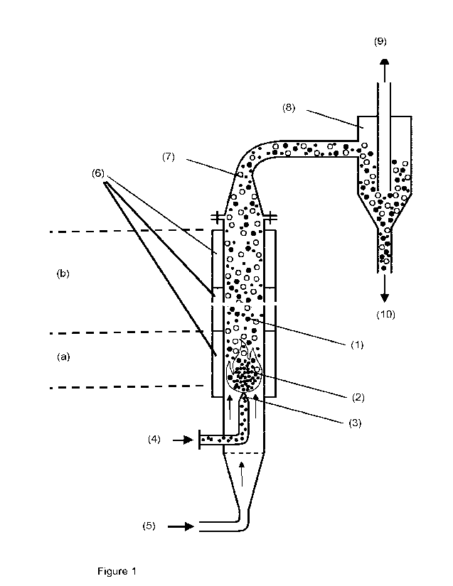
Figure 1 schematically represents a specific embodiment of a heating device
suitable for use
in the present process. It comprises a vertical, cylindrical reaction chamber
and the
precursor-particles are added to the flammable gas. The reaction chamber (1)
is cylindrical
and comprises two different zones, a combustion zone (a) and a cooling zone
(b). In the
combustion zone (a) a flame (2) is burning. The flame is fed by a flammable
gas which exits
from a burner nozzle (3). The heating device furthermore comprises one inlet
for the
flammable gas (4).
Details about flammable gases, burner nozzles and mixing flammable gases with
air or
oxygen have already been disclosed above. In the embodiment of figure 1, a one-
component
CA 03165336 2022- 7- 19
WO 2021/148285
PCT/EP2021/050570
14
nozzle is shown and consequently a flammable gas pre-mixed with oxygen or air
needs to be
introduced through the inlet (4). The diameter of the reaction chamber may be
chosen by the
skilled artisan according to his/her needs. As detailed above, the term
"diameter" refers to
the hydraulic diameter of the reaction chamber. It may be for example from 0.1
to 3 m, for
example from 1 to 3 m without wishing to limit this invention by said numbers.
In other embodiments of the invention, a plurality of burner nozzles and a
plurality of flames
is used. A plurality of nozzles preferably is arranged in such a manner, that
flames are
present in the entire cross section of the combustion zone (a). An embodiment
comprising a
plurality of burner nozzles is schematically shown in Figure 2. Figure 3 shows
schematically
a view on the burner nozzles from above: 8 burner nozzles (3) arranged in the
cylindrical
reaction chamber in a circular manner. The flammable gas flows from the inlet
(4) into a ring
line (11), which feeds all of the burner nozzles with the flammable gas. The
nozzles can be
arranged vertically as shown in figure 3, but they may also be tilted a bit
towards the center
of the ring and/or the other direction. It is the aim of such an arrangement
of the nozzles, that
flames are present in the entire cross section of the combustion zone. In one
embodiment,
the nozzles may be tilted from the vertical center line by an angle from 1 to
300
.
The heating device furthermore comprises an entry (5) for a non-flammable gas
as shown in
figure 1. Such an additional non-flammable gas supports the transport of the
hollow spherical
glass particles towards to outlet and assists to avoid back-mixing. Examples
of non-
flammable gases comprise air, carbon dioxide or reused gas from the process
itself.
The inner walls of the reaction chamber in the combustion zone (a) are
preferably protected
by a refractory material to withstand the high temperatures. Suitable
refractory materials are
known in the art. Examples comprise ceramic materials based on aluminium
and/or silicon
oxides or carbidic materials such as silicon carbide. Also, OCMC (oxide
ceramic matrix
composite) materials may be used. In one embodiment of the invention, the
refractory
materials are cooled. Such a cooling may be effectuated by using a reaction
chamber which
is doubled walled at least in the combustions zone (a). In other embodiments,
also the
cooling zone (b) may be double walled for the purposes of cooling. For
cooling, preferably, a
stream of a gas at ambient temperatures may be blown into the hollow space
through an
inlet and hot gas removed through an outlet. The hollow space between the two
walls may
be divided into several sections, each comprising an inlet and an outlet for a
coolant,
preferably a gas as outlined above, so that the walls of different zones of
the reaction
chamber can be cooled independently from each other.
Fig. 1 schematically represents a heating device comprising a reaction chamber
comprising
three different zones (6) for cooling the walls.
The heating device furthermore comprises an outlet (7). The outlet serves for
removing the
hollow spherical glass particles formed in course of the heat treatment from
the reaction
CA 03165336 2022- 7- 19
WO 2021/148285
PCT/EP2021/050570
chamber. It furthermore serves for removing waste gas formed in course of
combustion from
the reaction chamber as well as for removing non-flammable gas injected into
the reaction
chamber.
5 The heating device furthermore comprises means for separating the hollow
spherical glass
particles from the waste gas and the non-flammable gas. Such a device may be a
cyclone
(8). The gases are removed through the outlet (9) and the hollow spherical
glass particles
are removed through another outlet (10). Of course, also other devices may be
used for
separation, such as for example filters.
In course of step (II) a stream of the precursor-particles is introduced into
the heating device,
thereby obtaining hollow spherical glass particles. Step (II) comprises at
least 5 sub-steps (11-
1), (11-2), (11-3), (11-4), and (11-5).
In course of step (11-1), a stream of the flammable gas is introduced through
the inlet (4),
transferred through a pipe to the burner nozzle(s) (3) which is/are located in
the combustion
zone (a) and a flame (2) is ignited.
In course of step (11-2), a stream of a non-flammable gas in introduced into
the combustion
zone (a) through the inlet (5) and transferred through the cooling zone (b) to
the outlet (7).
So, there is a stream of gas and particles in one direction from the inlet (5)
to the outlet (7).
In course of step (11-3), the precursor-particles are added into the heating
device and
contacted with the naked flame(s) in the combustion zone (a), thereby
obtaining a stream of
hollow spherical glass particles, waste-gas generated by combustion of the
flammable gas
and non-non-flammable gas.
In a first embodiment of the invention, the precursor-particles are added to
the stream of the
flammable gas. Methods of adding solids to a stream of gas so that the solids
may be
transported with the stream of gas are basically known in the art. For
example, the particles
may be added into a swirl chamber which is flowed through by at least a part
of the stream of
the flammable gas.
In a second embodiment, the non-flammable gas acts as carrier gas for the
precursor-
particles and the precursor-particles are added to the stream of the non-
flammable gas.
Of course, the precursor-particles may be added to both, the stream of the
flammable gas
and the stream of non-flammable gas. Furthermore, also other methods of adding
the
precursor-particles into the combustion zone and contacting them with the
naked flame(s)
may be applied.
CA 03165336 2022- 7- 19
WO 2021/148285
PCT/EP2021/050570
16
The first embodiment is schematically represented in figure 1. The precursor-
particles are
dispersed in the flammable gas and the stream of flammable gas and precursor
particles
added through the inlet (4) and transported through a pipe to the burner
nozzle(s) (3). The
precursor-particles pass through the entire flame and are converted in the
flame into hollow
spherical glass particles.
The thus formed hollow spherical glass particles are transported by a stream
of waste gas
generated by the combustion through the heating unit towards the outlet (7).
Furthermore, a
non-flammable gas is introduced into the reaction chamber through the inlet
(5) at a position
upstream of the naked flame(s). It is the aim of using such an additional non-
flammable gas
to avoid back-mixing and to support the transport of the hollow spherical
glass particles
towards to outlet.
The second embodiment is schematically represented in figure 4. The heating
device shown
in figure 4 is similar to that shown in figure 1. It is heated by a plurality
of flames (2) which are
fed by a flammable gas which is entered into the heating device through the
inlet (4). A
stream of non-flammable gas is entered into the inlet (5) and precursor-
particles are added to
said stream of non-flammable gas. The stream of the non-flammable gas and the
precursor-
particles is introduced into the reaction chamber at a position upstream of
the naked
flame(s), so that it passes through the flames, thereby forming hollow
spherical glass
particles. As shown in figure 4, it is advantageous to use a plurality of
flames, so that flames
are present at essentially the entire cross section of the combustion zone
(a). Such an
arrangement ensures a good contact between the flames and the precursor
particles and
enable therefore high process efficiency. The heating device shown in figure 4
furthermore
comprises a mixing chamber (12) in which the precursor particles (13) and a
stream of a
non-flammable gas (14) is pre-mixed. The pre-mix is then transferred into the
main line
through which the stream of non-flammable gas and precursor-particles is
transported to the
reaction chamber (1).
In the process according to the present invention, the contact time of the
precursor-particles
with the flame(s) is short. In one embodiment, it may be for example from
0.001 s to 1 s. The
contact time mainly depends on the length of the flame. The flame velocity
also is high. In
one embodiment, it may be for example from 5 m/s to 100 m/s.
In course step (11-4) the stream of hollow spherical glass particles, waste
gas and non-
flammable gas is passed them through the cooling zone (b), thereby cooling the
hollow
spherical glass particles. In the cooling zone (b), the hollow spherical glass
particles formed
in the combustion zone are allowed to cool at least to a temperature at which
the wall of the
hollow spherical glass particles becomes solid. In general, cooling the hollow
spherical glass
particles to a temperature which is about 500 C less than its respective
melting temperature
is sufficient without wishing to limit the invention to this range.
CA 03165336 2022- 7- 19
WO 2021/148285
PCT/EP2021/050570
17
Cooling already starts simply when the particles are no longer in contact with
the flame(s). In
one embodiment of the invention, cooling is supported by entering a non-
flammable gas such
as air, nitrogen, carbon dioxide or reused waste gas, preferably having
ambient temperature,
into the cooling zone. In this embodiment, the reaction chamber comprises
suitable means,
such as for example lead-in tubes, which allows entering a cooling gas into
the cooling zone
(b).
Preferably, the lead-in tubes may be arranged in such a manner that a part of
the stream of
injected gas is directed to the interior of the reaction chamber and that a
part of the stream
flows essentially parallel to the wall. Such an arrangement helps to avoid
that the hollow
spherical glass particles formed stick to the walls. Cooling the walls as
already outlined
above can support cooling.
Figure 5 schematically shows one embodiment of a heating device in which a non-
flammable
gas is entered into the cooling zone (b). The heating device depicted in
figure 5 is horizontal.
It comprises the elements of the heating device as already shown in figures 1
and 4. The
precursor-particles are added to a stream of a non-flammable gas.
Additionally, the cooling
zone (b) comprises inlets (16) for a non-flammable gas. The inlets are
arranged in such a
manner that the cooling gas streams downstream along the reactor wall so that
the reactor
wall is cooled. Figure 5 also shows two optional elements which may be used:
The inner
walls of the reaction chamber in the combustion zone (a) are preferably
protected by a
refractory material (17) to withstand the high temperatures. Furthermore, the
heating device
comprises flow straighteners (18) which assist to avoid back-mixing.
Figure 6 schematically shows another embodiment of entering a cooling gas into
the cooling
zone. The reaction chamber comprises openings (22) through which air from the
outside is
sucked into the reaction chamber and the air sucked in streams along the
reactor wall. A
plurality of such openings may be arranged in a circumferential manner. In one
embodiment,
the openings (22) may be arranged at the beginning of cooling zone (b) as
shown in figure 6,
but they may also be arranged at a more downstream position. Of course, a
plurality of such
opening may be arranged at different distances from the flames(s) in the
streaming direction.
Furthermore, figure 6 shows one further embodiment of the invention, namely
two-
component nozzles (23) which are fed with separate streams of air (21) and the
flammable
gas (20).
In course of step (11-5) the hollow spherical glass particles are separated
from the exhaust
gas flow. Such a separation may be carried out by usual technologies. In one
embodiment of
the invention, a cyclone is used. Figures 1, 4, and 5 schematically show
heating devices
equipped with a cyclone (8) for separating the hollow spherical glass
particles. The gases are
removed through the outlet (9) and the hollow spherical glass particles are
removed through
another outlet (10). Of course, the also other devices may be used may be used
for
CA 03165336 2022- 7- 19
WO 2021/148285
PCT/EP2021/050570
18
separation, such as for example filters. The gases may comprise residual
amounts of fine
particles which may be separated with an additional filter, for example an
electro filter.
Figure 7 shows a process flow diagram of one embodiment of a plant for
manufacturing
hollow spherical glass particles according to the process according to the
present invention.
It shows the reaction chamber (1) as described in detail above in which hollow
spherical
glass particles are manufactured as described above. The resultant product
stream
comprising waste gas and the hollow spherical glass particles is transferred
through the
outlet (7) to the cyclone (8) where the hollow spherical glass particles are
separated from the
gas stream and removed through an outlet (10). The line between the outlet and
the cyclone
comprises a heat exchanger (38) to further reduce the temperature of the
stream comprising
waste gas and the hollow spherical glass particles before it enters into the
cyclone (8). The
waste gas stream (9) is transferred through an electro filter (26) for
removing residual
fractions solids from the waste gas stream.
The waste gas stream (9) may be removed through the exit (27) and or
recirculated by
means of the compressor (25) to the reactor. Fresh non-flammable gas may be
entered
through the inlet (23). The stream of waste gas and/or fresh gas is divided
and a partial
stream (24) is introduced into the mixing chamber (12). The second partial
stream (28)
directly flows to the inlet (5). Into the mixing chamber (12), also precursor
particles (13) are
entered in and mixed with the partial gas stream (24). The obtained,
concentrated stream of
precursor-particles and waste gas and/or fresh gas is entered into second
partial stream (28)
and the combined streams entered through the inlet (5) into the reaction
chamber. A part of
the waste gas stream (39) may be branched-off, cooled by on or more than one
heat
exchanger(s) (38) and entered into the reaction chamber for cooling purposes
at outlined
above. The plant shown in figure 7 may be operated with fresh non-flammable
gas which is
entered through the inlet (23). In other embodiments, only a part of the waste
gas formed in
course of the reaction is removed through the exit (27) and another part is
recycled and re-
entered into the reaction chamber.
In other embodiments of the present invention, the heating device used for
step (II)
comprises at least
= an inlet for a flammable gas,
= optionally an inlet for a non-flammable gas,
= a cylindrical, rotatable reaction chamber which is rotatably mounted at
its ends in a
fixed front unit and a fixed rear unit, wherein the rotatable, cylindrical
reaction
chamber is arranged horizontal or inclined towards its rear end, and wherein
the
rotatable, cylindrical reaction chamber comprises at least two different zones
(a)
and (b), wherein
(a) is a combustion zone capable of being heated by least
one naked flame,
wherein at least one burner nozzle which is connected with the inlet for the
flammable gas is arranged in the combustion zone, and
CA 03165336 2022- 7- 19
WO 2021/148285
PCT/EP2021/050570
19
(b) is a cooling zone,
= a fixed front unit comprising at least a mounting for the cylindrical,
rotatable
reaction chamber, an inlet for a stream of a flammable gas which is connected
with
the burner nozzle arrange in zone (a), and optionally an inlet for a non-
flammable
gas,
= a fixed rear unit comprising at least a mounting for the cylindrical,
rotatable
reaction chamber, an outlet for hollow spherical glass particles and an outlet
for
waste gas, and
= means for rotating the cylindrical, rotatable reaction chamber around its
longitudinal axis
and step (II) is carried out as follows:
(11-0') rotating the cylindrical, rotatable reaction chamber around its
longitudinal axis,
(11-1') introducing a stream of the flammable gas through the inlet,
transferring it to the
burner nozzle(s) and igniting at least one naked flame,
(11-2') optionally introducing a stream of a non-flammable gas through the
inlet and
trans transferring it through the reaction chamber to the outlet,
(11-3') adding the precursor-particles into the heating device and contacting
them with
the naked flame(s) in the combustion zone (a) by
= adding the precursor-particles to the stream of the flammable gas, and/or
= adding the precursor-particles to the stream of the non-flammable gas,
thereby obtaining hollow spherical glass particles in a waste gas stream,
(11-4') cooling the hollow spherical glass particles in the waste gas stream
by passing
them through the cooling zone (b) by means of the rotational movement o, and
(11-5') removing the hollow spherical glass particles through the outlet for
hollow
spherical glass particles of the fixed rear unit and/or by separating the
hollow
spherical glass particles from the waste gas flow exiting through the waste
gas
outlet.
Figure 8 schematically represents a specific embodiment of such a heating
device. The
heating device comprises a fixed front part (30) and a fixed rear part (31). A
cylindrical,
rotatable reaction chamber (29) which is rotatably mounted at its ends in the
front unit (30)
and in the rear unit (31). The inner diameter of the cylindrical reaction
chamber may be for
example from 0.1 to 3 m, for example from Ito 3 m without wishing to limit
this invention by
said numbers.
The rotatable reaction chamber comprises a combustion zone (a) which is heated
by at least
one naked flame (3), preferably a plurality of flames and a cooling zone (b).
Details have
CA 03165336 2022- 7- 19
WO 2021/148285
PCT/EP2021/050570
already been described above and we refer to the corresponding sections above.
The inner
walls of the reaction chamber in the combustion zone (a) are preferably
protected by a
refractory material to withstand the high temperatures. Suitable refractory
materials have
already been mentioned above.
5
The fixed front unit (30) comprising at least a mounting (32) for mounting the
cylindrical
reaction chamber rotatably and an inlet for a flammable gas (4), which is
connected with a
burner nozzle (3) or preferably a plurality of burner nozzles arranged in zone
(a). So, the
burner nozzle(s) (3) are not connected with the rotatable reaction chamber but
extend from
10 the fixed front unit into zone (a). As detailed above, the burner
nozzles may be one-
component or two-component nozzles. The fixed front unit (30) may optionally
comprise an
inlet for a non-flammable gas.
The fixed rear unit also comprises at least a mounting (32) for the
cylindrical, rotatable
15 reaction chamber, and furthermore an outlet for hollow spherical
glass particles (34) and an
outlet for at least waste gas (35) but also at least a part of the hollow
spherical glass particles
may be removed from the heating unit through the outlet (35). The outlet (34)
preferably is at
the bottom of the fixed rear unit so that the hollow spherical glass particles
may be removed
by means of gravity. The outlet (35) may optionally be connected with a unit
for separating
20 hollow spherical glass particles from the waste gas stream, for
example a filter or a cyclone
as described above.
The heating unit furthermore comprises means (33) for rotating the
cylindrical, rotatable
reaction chamber around its longitudinal axis.
Figure 9 schematically shows another embodiment of a heating unit comprising a
rotatable
reaction chamber. In this embodiment, the inner wall of the combustion zone
(a) is protected
by a layer of a refractory material (36) and it furthermore comprises inlets
for air (37) for
cooling the walls of the cooling zone (b).
The rotatable, cylindrical reaction chamber is arranged horizontal or inclined
towards its rear
end. If the reaction chamber is inclined, the inclination angle of the
cylindrical, rotatable
reaction chamber may be from more than 0 to 200, preferably from more than 0
to 10 . The
transport of the hollow spherical glass particles may be affected by rotation
the cylindrical
reaction chamber alone, especially in connection with inclining the reaction
chamber. In other
embodiments, the cylindrical, rotatable reaction chamber comprises
installations in its interior
to support transport of the material such as for instance a screw. Of course,
also the waste
gas stream and optionally a stream of additional non-flammable gas may support
transport of
the products through the rotatable reaction chamber.
Figures 10 and 11 schematically shows an embodiment, in which the fixed front
unit of the
heating unit additionally comprises an inlet (5) for a non-flammable gas. In
figure 10, the
CA 03165336 2022- 7- 19
WO 2021/148285
PCT/EP2021/050570
21
precursor particles are added to the stream of the flammable gas and in figure
11, the
precursor-particles are added to the non-flammable gas.
Step (II) of the present embodiment of using a heating unit comprising a
rotatable reaction
chamber comprises at least 5 sub-steps (II-0'), (II-1'), (11-3'), (II-4'), and
(11-5'). Optionally, the
process can additionally comprise step (11-2').
In course of step (II-0'), the cylindrical, rotatable reaction chamber is
rotated around its
longitudinal axis. The rotational speed may be selected by the skilled artisan
and may be for
example from 0.5 to 10 revolutions per minute (rpm).
In course of step (II-1'), a stream of the flammable gas is introduced through
the inlet (4),
transferred through a pipe to the burner nozzle(s) (3) which is/are located in
the combustion
zone (a) and a flame (2) is ignited.
In course of step (II-3'), the precursor-particles are added into the heating
device and
contacted with the naked flame(s) in the combustion zone (a), thereby
obtaining a stream of
hollow spherical glass particles, waste-gas generated by combustion of the
flammable gas
and non-non-flammable gas.
In a first embodiment of step (II-3'), the precursor-particles are added to
the stream of the
flammable gas. Details about adding the precursor particles to the stream of
the flammable
gas have already been mentioned above. Methods of adding solids to a stream of
gas have
already been described above. For example, a mixing chamber as described above
may be
used. Such an embodiment is schematically shown in figures 8, 9, and 10. In
one
embodiment, which is schematically shown in figure 10, an additional stream of
non-
flammable gas is entered in through the inlet (5). As indicated above, such an
additional non-
flammable gas may assist to avoid back-mixing and to support the transport of
the hollow
spherical glass particles towards to outlet.
In a second embodiment of step (II-3'), the fixed front unit additionally
comprises an inlet (5)
for a non-flammable gas as indicated in figure 11, and the process comprises a
step (II-2'), in
which a stream of a non-flammable gas in introduced into the heating device
through said
inlet (5) and transferred through the rotating reaction chamber (29) to the
outlet (35). The
precursor-particles are added to the stream of non-flammable gas. So, in this
embodiment,
the non-flammable gas acts as carrier gas.
In course step (11-4') the stream of hollow spherical glass particles, waste
gas and optionally
non-flammable gas is passed them through the cooling zone (b), thereby cooling
the hollow
spherical glass particles. As already detailed above, in the cooling zone (b),
the hollow
spherical glass particles formed in the combustion zone (a) are allowed to
cool to at least a
temperature at which the wall of the hollow spherical glass particles becomes
solid. In one
CA 03165336 2022- 7- 19
WO 2021/148285
PCT/EP2021/050570
22
embodiment of the invention, cooling is supported by entering a non-flammable
gas such as
air or nitrogen, preferably having ambient temperature, into the cooling zone.
In this
embodiment, the reaction chamber comprises suitable means, such as for example
lead-in
tubes, which allows entering a cooling gas into the cooling zone (b).
Preferably, lead-in tubes
may be arranged such that a stream of injected gas flows essentially parallel
to the wall.
Such an arrangement helps to avoid that the hollow spherical glass particles
formed stick to
the walls.
In course of step (11-5') the hollow spherical glass particles are removed
from the heating
device through the outlet (34) of the fixed rear unit and/or the hollow
spherical glass particles
are separated from the waste gas flow or optionally from the stream of waste
gas and non-
flammable gas additionally injected which exits through the outlet (35). As
indicated above
for such a separation for example a filter unit or a cyclone may be used.
Devices for carrying out the process
In another embodiment, the present invention relates to a heating device for
heat-treating
precursor-particles comprising SiO2, A1203, and an alkali metal oxide at a
temperature from
1000 to 1800 C thereby obtaining hollow spherical glass particles, comprising
at least
= a longitudinal reaction chamber comprising at least two different zones (a)
and
(b), wherein
(a) is a combustion zone capable of being heated by least one naked flame,
wherein at least one burner nozzle which is connected with an inlet for the
flammable gas is arranged in the combustion zone,
(b) is a cooling zone, and
= an inlet for the flammable gas,
= an inlet for introducing a non-flammable gas into the combustion zone
(a),
= means for adding precursor-particles comprising SiO2, A1203, and an
alkali metal
oxide to the flammable gas and/or the non-flammable gas,
= an outlet for removing hollow spherical glass particles, non-flammable gas
and
waste from the cooling zone (b).
Details of such a heating device including preferred embodiments have already
been
disclosed above and we refer to the respective passages of the specification
above.
In yet another embodiment, the present invention relates to a heating device
for heat-treating
precursor-particles comprising SiO2, A1203, and an alkali metal oxide at a
temperature from
1000 to 1800 C thereby obtaining hollow spherical glass particles, comprising
at least
= an inlet for a flammable gas,
CA 03165336 2022- 7- 19
WO 2021/148285
PCT/EP2021/050570
23
= optionally an inlet for a non-flammable gas,
= a cylindrical, rotatable reaction chamber which is rotatably mounted at
its ends in a
fixed front unit and a fixed rear unit, wherein the rotatable, cylindrical
reaction
chamber is arranged horizontal or inclined towards its rear end, and wherein
the
rotatable, cylindrical reaction chamber comprises at least two different zones
(a)
and (b), wherein
(a) is a combustion zone capable of being heated by least
one naked flame,
wherein at least one burner nozzle which is connected with the inlet for the
flammable gas is arranged in the combustion zone, and
(b) is a cooling zone,
= a fixed front unit comprising at least a mounting for the cylindrical,
rotatable
reaction chamber, an inlet for a stream of a flammable gas which is connected
with
the burner nozzle arrange in zone (a), and optionally an inlet for a non-
flammable
gas,
= a fixed rear unit comprising at least a mounting for the cylindrical,
rotatable
reaction chamber, an outlet for hollow spherical glass particles and an outlet
for
waste gas, and
= a drive for rotating the cylindrical, rotatable reaction chamber around
its
longitudinal axis.
Details of such a heating device including preferred embodiments have already
been
disclosed above and we refer to the respective passages of the specification
above.
Use of the hollow spherical glass particles
The invention furthermore relates to the use of hollow spherical glass
particles comprising at
least SiO2, A1203, and an alkali metal oxide as filler for high temperature
products, molten
metal, injection molded synthetic materials, flame-retardant insulating foams,
cement
slurries, mortars, concretes and oil field applications, wherein the hollow
spherical glass
particles are manufactured by a process as described above.
In yet another embodiment, the invention relates to the use of hollow
spherical glass particles
comprising at least SiO2, A1203, and an alkali metal oxide as additive for
molten metals
having a melting point of at least 500 C, wherein the hollow spherical glass
particles are
manufactured by a process as described above.
Details of the hollow spherical glass particles including preferred
embodiments and details of
the process including preferred embodiments have already been disclosed above
and we
refer to the respective passages of the specification above.
CA 03165336 2022- 7- 19
WO 2021/148285
PCT/EP2021/050570
24
Preferably, the hollow spherical glass particles to be used as described above
comprise at
least 30 wt.-% of SiO2, at least 25 wt.-% of A1203, and at least 18 wt.-% of
the alkali metal
oxide, preferably Na2O in each case based on the overall weight of the hollow
spherical glass
particles and are free of boron. Furthermore, preferably the average diameter
of the hollow
spherical glass particles to be used as described above is from 20 pm to 200
pm.
In the process for making such particles to be used as described above
preferably a starting
composition comprising at least a zeolite, a clay and an alkali metal
carbonate is used and
the temperature of the heat-treatment is from 1300 C to 1600 C.
Advantages of the present invention
The described process according to the present invention of heat-treating the
precursor
particles by contacting them with at least one naked flame for obtaining
hollow spherical
glass particles has advantages over prior art.
Because the heating device is internally heated by naked flame(s) and heat-
treatment is
carried out by contacting the precursor-particles with the naked flame(s),
there is no problem
of heat-transfer into the heating device and therefore advantageously, the
inner diameter of
the cylindrical heating device may be made very large. It may be for example
from 0.1 to 3
m, for example from 1 to 3 m without wishing to limit this invention by said
numbers. Enabling
such large diameter facilitates significantly the construction of production
plants having a
high capacity. The scale up from laboratory or pilot production plants is
facilitated by simply
enlarging the number of burner nozzles and the diameter of the reaction
chamber.
CA 03165336 2022- 7- 19