Note: Descriptions are shown in the official language in which they were submitted.
[Document Type] Specification
[Title of the Invention] METHOD OF MANUFACTURING LAMINATED CORE
[Technical Field of the Invention]
[0001]
The present invention relates to a method of manufacturing a laminated core.
Priority is claimed on Japanese Patent Application No. 2020-104252, filed
June 17, 2020, the content of which is incorporated herein by reference.
[Background Art]
[0002]
A laminated core used in a motor (rotating electrical machine) is
manufactured by punching an electrical steel sheet into a predetermined shape
and
laminating the punched steel sheet in a die. Recently, in order to reduce iron
loss in
motor products, an electrical steel sheet having a reduced thickness is used
for these
products. However, in the electrical steel sheet having a reduced thickness,
there is a
problem that does not occur in a method of manufacturing a laminated core in
the
related art. For example, the number of times of punching increases. The
reason for
this is that, when the sheet thickness of the electrical steel sheet is
reduced to half of
that in the related art, the number of times of punching is doubled. In order
to secure
productivity equivalent to that in the related art, it is necessary to
increase the punching
speed. It is necessary to reduce the sheet thickness of the electrical steel
sheet to
narrow a clearance of a punching die, and there is a limit in increasing the
punching
speed in order to secure the lifetime of the punching die.
[0003]
Patent Document 1 describes a method of manufacturing a laminated core.
Patent Document 1 describes a technique of bonding two or more electrical
steel sheets
CA 03165613 2022-7-21 - 1 -
and punching the laminate in order to improve productivity. However, in Patent
Document 1, the laminate is heated to completely cure or incompletely cure an
adhesive layer formed between the electrical steel sheets. Therefore, the
productivity
cannot be sufficiently improved.
[Prior Art Document]
[Patent Document]
[0004]
[Patent Document 11 Japanese Unexamined Patent Application, First
Publication No. 2005-191033
[Disclosure of the Invention]
[Problems to be Solved by the Invention]
[0005]
The present invention has been made in consideration of the above-described
circumstances, and an object thereof is to provide a method of manufacturing a
laminated core having excellent productivity.
[Means for Solving the Problem]
[0006]
The summary of the present invention is as follows.
(1) According to one aspect of the present invention, there is provided a
method of manufacturing a laminated core by punching electrical steel strips
including
an insulation coating to obtain core single sheets and laminating the core
single sheets,
the method including:
pressurizing two or more electrical steel strips using a guide roller to
temporarily bond the electrical steel strips immediately before the punching;
and
obtaining the core single sheets by performing the punching after inserting
the
CA 03165613 2022-7-21 - 2 -
two or more electrical steel strips after the temporary bonding into a
punching die.
(2) In the method of manufacturing a laminated core according to (1), a
surface temperature of the two or more electrical steel strips during the
temporary
bonding may be 15 C to 50 C.
(3) In the method of manufacturing a laminated core according to (1) or (2),
an applied pressure during the pressurization by the guide roller may be 2.0
to 10.0
MPa.
(4) In the method of manufacturing a laminated core according to any one of
(1) to (3), after the punching, the core single sheets may be heated to 180 C
to 250 C
to mainly bond the core single sheets.
(5) In the method of manufacturing a laminated core according to any one of
(1) to (4), the insulation coating may have adhesiveness.
[Effects of the Invention]
[0007]
In the above-described aspect according to the present invention, a method of
manufacturing a laminated core having excellent productivity can be provided.
[Brief Description of the Drawings]
[0008]
FIG. 1 is a cross-sectional view showing a rotating electrical machine
including a laminated core.
FIG. 2 is a side view showing the laminated core.
FIG. 3 is an A-A cross-sectional view of FIG 2.
FIG 4 is a plan view showing a material for forming the laminated core.
FIG. 5 is a B-B cross-sectional view of FIG 4.
FIG 6 is an enlarged view showing a C portion of FIG 5.
CA 03165613 2022-7-21 - 3 -
FIG 7 is a side view showing a manufacturing device used for manufacturing
the laminated core.
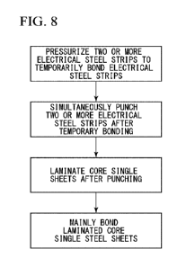
FIG 8 is a flowchart showing a method of manufacturing the laminated core
according to the embodiment.
[Embodiments of the Invention]
[0009]
Hereinafter, a method of manufacturing a laminated core according to one
embodiment of the present invention will be described with reference to the
drawings.
First, a laminated core manufactured using the method of manufacturing a
laminated
core according to the embodiment, a rotating electrical machine including the
laminated core, and a material for forming the laminated core will be
described. In
the embodiment, an electric motor, specifically an AC motor, more specifically
a
synchronous motor, and still more preferably a permanent magnet motor will be
described as an example of the rotating electrical machine. As this electric
motor, for
example, an electric vehicle is suitably adopted.
[0010]
(Rotating Electrical Machine 10)
As shown in FIG 1, the rotating electrical machine 10 includes a stator 20, a
rotor 30, a case 50, and a rotating shaft 60. The stator 20 and the rotor 30
are housed
in the case 50. The stator 20 is fixed to the inside of the case 50.
In the embodiment, an inner rotor type where the rotor 30 is positioned inward
in a radial direction of the stator 20 is adopted as the rotating electrical
machine 10.
However, an outer rotor type where the rotor 30 is positioned outside the
stator 20 may
be adopted as the rotating electrical machine 10. In addition, in the
embodiment, the
rotating electrical machine 10 is a 12-pole 18-slot three-phase AC motor.
However,
CA 03165613 2022-7-21 - 4 -
the number of poles, the number of slots, the number of phases, and the like
can be
appropriately changed.
For example, when an excitation current having an effective value of 10 A and
a frequency of 100 Hz is applied at each of the phases, the rotating
electrical machine
can rotate at a rotation speed of 1000 rpm.
[00111
The stator 20 includes a laminated core for bonding a stator (hereinafter,
stator
core) 21 and a winding (not shown).
The stator core 21 includes an annular core back portion 22 and a plurality of
tooth portions 23. Hereinafter, a central axis 0 direction of the stator core
21 (or the
core back portion 22) will be referred to as the axial direction, a radial
direction
(direction perpendicular to the central axis 0) of the stator core 21 (or the
core back
portion 22) will be referred to as the radial direction, and a circumferential
direction
(direction around the central axis 0) of the stator core 21 (or the core back
portion 22)
will be referred to as the circumferential direction.
[00121
The core back portion 22 is formed in a toric shape in a plan view when the
stator 20 is seen from the axial direction.
The plurality of tooth portions 23 protrude inward in the radial direction
(toward the central axis 0 of the core back portion 22 in the radial
direction) from an
inner circumference of the core back portion 22. The plurality of tooth
portions 23
are disposed at regular angular intervals in the circumferential direction. In
the
embodiment, 18 tooth portions 23 are provided at intervals of a central angle
of 20
degrees around the central axis 0. The plurality of tooth portions 23 are
formed in
the same shape and the same size. Accordingly, the plurality of tooth portions
23
CA 03165613 2022-7-21 - 5 -
have the same thickness.
The winding is coiled around the tooth portions 23. The winding may be in
a concentrated winding state or in a distributed winding state.
[0013]
The rotor 30 is disposed inward in the radial direction with respect to the
stator 20 (stator core 21). The rotor 30 includes a rotor core 31 and a
plurality of
permanent magnets 32.
The rotor core 31 is formed in an annular (toric) shape that is disposed on
the
same axis as the stator 20. In the rotor core 31, the rotating shaft 60 is
disposed.
The rotating shaft 60 is fixed to the rotor core 31.
The plurality of permanent magnets 32 are fixed to the rotor core 31. In the
embodiment, one set including two permanent magnets 32 forms one magnetic
pole.
Plural sets of permanent magnets 32 are disposed at regular angular intervals
in the
circumferential direction. In the embodiment, 12 sets of permanent magnets 32
(24
permanent magnets 32 in total) are provided at intervals of a central angle of
30
degrees around the central axis 0.
[0014]
In the embodiment, an embedded magnet motor is adopted as the permanent
magnet motor. In the rotor core 31, a plurality of through-holes 33 that
penetrate the
rotor core 31 in the axial direction are formed. The plurality of through-
holes 33 are
provided corresponding to the arrangement of the plurality of permanent
magnets 32.
Each of the permanent magnets 32 is fixed to the rotor core 31 in a state
where it is
disposed in the corresponding through-hole 33. The fixing of the rotor core 31
to
each of the permanent magnets 32 can be realized, for example, by bonding an
outer
surface of the permanent magnet 32 and an inner surface of the through-hole 33
using
CA 03165613 2022-7-21 - 6 -
an adhesive. As the permanent magnet motor, a surface magnet motor may be
adopted instead of the embedded magnet type.
[00151
Both of the stator core 21 and the rotor core 31 are the laminated cores. For
example, as shown in FIG 2, the stator core 21 is formed by laminating a
plurality of
core single sheets 40 in a laminating direction.
The lamination thickness (overall length along the central axis 0) of each of
the stator core 21 and the rotor core 31 is, for example, 50.0 mm. The outer
diameter
of the stator core 21 is, for example, 250.0 mm. The inner diameter of the
stator core
21 is, for example, 165.0 mm. The outer diameter of the rotor core 31 is, for
example,
163.0 mm. The inner diameter of the rotor core 31 is, for example, 30.0 mm.
These
values are exemplary, and the lamination thickness and the outer diameter or
inner
diameter of the stator core 21 and the lamination thickness and the outer
diameter or
inner diameter of the rotor core 31 are not limited to only these values.
Here, the
inner diameter of the stator core 21 is based on tip end portions of the tooth
portions 23
in the stator core 21. That is, the inner diameter of the stator core 21 is
the diameter
of an imaginary circle inscribed in the tip end portions of all of the tooth
portions 23.
[00161
Each of the core single sheets 40 that form the stator core 21 and the rotor
core 31 is formed, for example, by punching a material 1 shown in FIGS. 4 to
6. The
material 1 is a steel sheet (electrical steel sheet) as a base metal of the
core single sheet
40. Examples of the material 1 include a strip-shaped steel sheet or a
cut sheet.
Although the description of the laminated core is ongoing, the material 1 will
be described below. In the present specification, the strip-shaped steel sheet
as the
base metal of the core single sheet 40 will also be referred to as the
material 1 or the
CA 03165613 2022-7-21 - 7 -
electrical steel strip 1. A steel sheet obtained by punching the material 1 or
the
electrical steel strip 1 in a shape used for the laminated core will also be
referred to as
the core single sheet 40.
[00171
(Material 1)
The material 1 is handled, for example, in a state where it is coiled around a
coil 1A. In the embodiment, a non-oriented electrical steel sheet is adopted
as the
material 1. Anon-oriented electrical steel strip of JIS C 2552:2014 is adopted
as the
non-oriented electrical steel sheet. However, a grain-oriented electrical
steel sheet
may be adopted as the material 1 instead of the non-oriented electrical steel
sheet. In
this case, a grain-oriented electrical steel strip of JIS C 2553:2019 is
adopted as the
grain-oriented electrical steel sheet. In addition, a non-oriented thin
electrical steel
strip and a grain-oriented thin electrical steel strip of JIS C 2558:2015 can
be adopted.
[00181
Upper and lower limits of an average sheet thickness tO of the material 1 are
set, for example as follows in consideration that the material 1 is used as
the core
single sheet 40.
As the sheet thickness of the material 1 decreases, the manufacturing cost of
the material 1 increases. Therefore, in consideration of the manufacturing
cost, the
lower limit of the average sheet thickness tO of the material 1 is 0.10 mm,
preferably
0.15 mm, and more preferably 0.18 mm.
On the other hand, when the thickness of the material 1 is excessively large,
the manufacturing cost is improved. When the material 1 is used as the core
single
sheet 40, the eddy-current loss increases, and core iron loss deteriorates.
Therefore,
in consideration of the core iron loss and the manufacturing cost, the upper
limit of the
CA 03165613 2022-7-21 - 8 -
average sheet thickness tO of the material 1 is 0.65 mm, preferably 0.35 mm,
and more
preferably 0.30 mm.
The average sheet thickness tO of the material 1 that satisfies the above-
described range is, for example, 0.20 mm.
[0019]
The average sheet thickness tO of the material 1 includes not only the
thickness of a base steel sheet 2 described but also the thickness of an
insulation
coating 3. In addition, a method of measuring the average sheet thickness tO
of the
material 1 is, for example, the following measurement method. For example,
when
the material 1 is coiled in a shape of the coil 1A, at least a part of the
material 1 is
uncoiled in a flat shape. In the material 1 that is uncoiled in a flat shape,
a
predetermined position of the material 1 in a longitudinal direction (for
example, a
position distant from an end edge of the material 1 in the longitudinal
direction by a
length corresponding to 10% of the overall length of the material 1) is
selected. At
this selected position, the material 1 is divided into five regions in a width
direction
thereof. At four portions as boundaries of the five regions, the sheet
thickness of the
material 1 is measured. The average value of the sheet thicknesses at the four
portions can be obtained as the average sheet thickness tO of the material 1.
[0020]
Of course, the upper and lower limits of the average sheet thickness tO of the
material 1 can also be adopted as upper and lower limits of the average sheet
thickness
tO as the core single sheet 40. A method of measuring the average sheet
thickness tO
of the core single sheet 40 is, for example, the following measurement method.
For
example, the lamination thickness of the laminated core is measured at four
portions at
regular intervals in the circumferential direction (that is, at intervals of
90 degrees
CA 03165613 2022-7-21 - 9 -
around the central axis 0). Each of the measured lamination thicknesses at the
four
portions is divided by the number of the laminated core single sheets 40 to
calculate
the sheet thickness per sheet. The average value of the sheet thicknesses at
the four
portions can be obtained as the average sheet thickness tO of the core single
sheet 40.
[0021]
As shown in FIGS. 5 and 6, the material 1 includes the base steel sheet 2 and
the insulation coating 3. In the material 1, both surfaces of the strip-shaped
base steel
sheet 2 are covered with the insulation coating 3. In the embodiment, most of
the
material 1 is formed of the base steel sheet 2, and the insulation coating 3
that is
thinner than the base steel sheet 2 is formed on the surface of the base steel
sheet 2.
[0022]
The chemical composition of the base steel sheet 2 includes 2.5% to 4.5% of
Si by mass% as represented by mass% below. By adjusting the chemical
composition
to be in this range, the yield strength of the material 1 (core single sheet
40) can be set
to be, for example, 380 to 540 MPa.
[0023]
Si: 2.5% to 4.5%
Al: 0.001% to 3.0%
Mn: 0.05% to 5.0%
Remainder: Fe and Impurities
[0024]
When the material 1 is used as the core single sheet 40, the insulation
coating
3 exhibits insulation properties between the core single sheets 40 adjacent to
each other
in the laminating direction. In addition, in the embodiment, the insulation
coating 3
has adhesiveness such that the core single sheets 40 adjacent to each other in
the
CA 03165613 2022-7-21 - 10 -
laminating direction are bonded to each other. The insulation coating 3 may
have a
single layer configuration or a multilayer configuration. More specifically,
for
example, the insulation coating 3 may have a single layer configuration having
insulation properties and adhesiveness or may have a multilayer configuration
that
includes an underlayer insulation coating having excellent insulation
properties and an
upper layer insulation coating having excellent adhesiveness.
[0025]
In the embodiment, the insulation coating 3 covers the entire surface of both
surfaces of the base steel sheet 2 without a gap. However, within a range
where the
insulation properties or the adhesiveness are secured, a part of the
insulation coating 3
does not need to cover both surfaces of the base steel sheet 2 without a gap.
In other
words, a part of the insulation coating 3 may be intermittently provided on
the surfaces
of the base steel sheet 2. However, in order to secure the insulation
properties, both
surfaces of the base steel sheet 2 need to be covered with the insulation
coating 3 such
that the entire surface is not exposed. Specifically, when the insulation
coating 3 has
the single layer configuration having not only insulation properties but also
adhesiveness without including the underlayer insulation coating having
excellent
insulation properties, the insulation coating 3 needs to be formed over the
entire
surface of the base steel sheet 2 without a gap. On the other hand, when the
insulation coating 3 has the multilayer configuration that includes an
underlayer
insulation coating having excellent insulation properties and an upper layer
insulation
coating having excellent adhesiveness, both of the underlayer insulation
coating and
the upper layer insulation coating are formed on the entire surface of the
base steel
sheet 2 without a gap. In addition, even if the underlayer insulation coating
is formed
on the entire surface of the base steel sheet without a gap and the upper
layer insulation
CA 03165613 2022-7-21 - 11 -
coating is intermittently provided, both of insulation properties and
adhesiveness can
be achieved at the same time.
[0026]
A coating composition for forming the underlayer insulation coating is not
particularly limited. For example, a general treatment agent such as a chromic
acid-
containing treatment agent or a phosphate-containing treatment can be used.
[0027]
The insulation coating having adhesiveness is formed by coating the base
steel sheet with a coating composition for an electrical steel sheet described
below.
The insulation coating having adhesiveness is the insulation coating that has
the single
layer configuration having not only insulation properties but also
adhesiveness or the
upper layer insulation coating that is formed on the underlayer insulation
coating.
The insulation coating having adhesiveness is in an uncured state or a semi-
cured state
(B stage) before heating pressurization for manufacturing the laminated core,
and
exhibits adhesiveness when the curing reaction progresses by heating during
the
heating pressurization.
[0028]
A typical insulating film has insulation properties but does not have
adhesiveness. As described above the insulating film according to the
embodiment is
largely different from the typical insulation coating and an adhesive layer
formed of an
adhesive in that it has adhesiveness and insulation properties.
[0029]
In addition, as a method of bonding the base steel sheets 2 on which the
insulation coating not having adhesiveness is formed, a method of bonding the
base
steel sheets 2 using an adhesive formed of a thermosetting resin having
adhesiveness
CA 03165613 2022-7-21 - 12 -
can be used. In the core single sheet 40 that is manufactured by bonding the
base
steel sheets 2 using this method, two or more base steel sheets 2 are bonded
before
punching. Therefore, although the base steel sheets 2 in the core single sheet
40 are
bonded, the two or more core single sheets 40 in the bonded state are not
bonded to
each other. Therefore, a process of separately applying an adhesive to any one
of
front and rear surfaces of the core single sheets 40 is necessary, and the
productivity
deteriorates. When an adhesive is further used for the insulation coating
having
adhesiveness and insulation properties, the space factor decreases, and thus a
laminated
core having poor magnetic characteristics is obtained.
[00301
The coating composition for an electrical steel sheet is not particularly
limited,
and examples thereof include a composition including an epoxy resin and an
epoxy
resin curing agent. That is, examples of the insulation coating having
adhesiveness
include a film including an epoxy resin and an epoxy resin curing agent.
[0031]
As the epoxy resin, a general epoxy resin can be used. Specifically, any
epoxy resin having two or more epoxy groups in one molecule can be used
without any
particular limitation. Examples of the epoxy resin include a bisphenol A epoxy
resin,
a bisphenol F epoxy resin, a phenol novolac epoxy resin, a cresol novolac
epoxy resin,
an alicyclic epoxy resin, a glycidyl ester epoxy resin, a glycidylamine epoxy
resin, a
hydantoin epoxy resin, an isocyanurate epoxy resin, an acrylic acid-modified
epoxy
resin (epoxy acrylate), a phosphorus-containing epoxy resin, and a halide
(brominated
epoxy resin) or a hydrogenated product thereof. The epoxy resins may be used
alone
or in combination of two or more kinds.
[00321
CA 03165613 2022-7-21 - 13 -
The coating composition for an electrical steel sheet may include an acrylic
resin.
The acrylic resin is not particularly limited. Examples of a monomer used
for the acrylic resin include an unsaturated carboxylic acid such as acrylic
acid or
methacrylic acid and a (meth)acrylate such as methyl (meth)acrylate, ethyl
(meth)acrylate, n-butyl (meth)acrylate, isobutyl (meth)acrylate, cyclohexyl
(meth)acrylate, 2-ethylhexyl (meth)acrylate, 2-hydroxyethyl (meth)acrylate, or
hydroxypropyl (meth)acrylate. The (meth)acrylate refers acrylate or
methacrylate.
The acrylic resins may be used alone or in combination of two or more kinds.
[0033]
The acrylic resin may include a constituent unit derived from another
monomer other than the acrylic monomer. Examples of the other monomer include
ethylene, propylene, and styrene. The other monomers may be used alone or in
combination of two or more kinds.
[0034]
When an acrylic resin is used, the other monomer is used for an acrylic
modified epoxy resin in which an acrylic resin is grafted with an epoxy resin.
The
coating composition for an electrical steel sheet may include the other
monomer as a
monomer for forming an acrylic resin.
[0035]
As the epoxy resin curing agent, a thermally curable curing agent having
latency can be used, and examples thereof include an aromatic polyamine, an
acid
anhydride, a phenol curing agent, a dicyandiamide, a boron trifluoride-amine
complex,
and an organic acid hydrazide. Examples of the aromatic polyamine include meta-
phenylenediamine, diaminodiphenyl methane, and diaminodiphenyl sulfone.
CA 03165613 2022-7-21 - 14 -
Examples of the phenol curing agent include a phenol novolac resin, a cresol
novolac
resin, a bisphenol novolac resin, a triazine-modified phenol novolac resin,
and a phenol
resole resin. In particular, as the epoxy resin curing agent, a phenol curing
agent is
preferable, and a phenol resole resin is more preferable. The epoxy resin
curing
agents may be used alone or in combination of two or more kinds.
[0036]
The content of the epoxy resin curing agent in the coating composition for an
electrical steel sheet is preferably 5 to 35 parts by mass and more preferably
10 to 30
parts by mass with respect to 100 parts by mass of the epoxy resin.
[0037]
In the coating composition for an electrical steel sheet, an additive such as
a
curing accelerator (curing catalyst), an emulsifier, or an antifoaming agent
may be
mixed. The additives may be used alone or in combination of two or more kinds.
[0038]
Upper and lower limits of an average thickness ti of the insulation coating 3
are set, for example as follows in consideration that the material 1 is used
as the core
single sheet 40. When the material 1 is used as the core single sheet 40, the
average
thickness ti of the insulation coating 3 (the thickness per single surface of
the core
single sheet 40 (material 1)) is adjusted such that the insulation properties
and the
adhesiveness of the laminated core single sheets 40 can be secured.
[0039]
In the insulation coating 3 having the single layer configuration, the average
thickness ti of the insulation coating 3 (the thickness per single surface of
the core
single sheet 40 (material 1)) can be, for example, 1.5 1.1.m or more and 8.0
!lin or less.
In the insulation coating 3 having the multilayer configuration, the average
CA 03165613 2022-7-21 - 15 -
thickness of the underlayer insulation coating can be, for example, 0.3 gm or
more and
1.2 gm or less and is preferably 0.7 gm or more and 0.9 gm or less. The
average
thickness of the upper layer insulation coating can be, for example, 1.5 gm or
more and
8.0 gm or less.
As a method of measuring the average thickness ti of the insulation coating 3
in the material 1, the average thickness ti can be obtained by obtaining the
thicknesses
of the insulation coating 3 at a plurality of positions and obtaining the
average value of
the thicknesses as in the average sheet thickness tO of the material 1.
[0040]
Of course, the upper and lower limits of the average thickness ti of the
insulation coating 3 in the material 1 can also be adopted as upper and lower
limits of
the average thickness ti of the insulation coating 3 as the core single sheet
40. A
method of measuring the average thickness ti of the insulation coating 3 in
the core
single sheet 40 is, for example, the following measurement method. For
example,
among the plurality of core single sheets 40 forming the laminated core, the
core single
sheet 40 that is positioned on the outermost side in the laminating direction
(the core
single sheet 40 having a surface that is exposed in the laminating direction)
is selected.
On the surface of the selected core single sheet 40, a predetermined position
in the
radial direction (for example, a position at the exact center of an inner
circumference
and an outer circumference of the core single sheet 40) is selected. At the
selected
position, the thickness of the insulation coating 3 in the core single sheet
40 is
measured at four portions at regular intervals in the circumferential
direction (that is, at
intervals of 90 degrees around the central axis 0). The average value of the
measured
thicknesses at the four portions can be obtained as the average thickness ti
of the
insulation coating 3.
CA 03165613 2022-7-21 - 16 -
The reason for measuring the average thickness tl of the insulation coating 3
in the core single sheet 40 that is positioned on the outermost side in the
laminating
direction is that the insulation coating 3 is formed such that the thickness
of the
insulation coating 3 does not substantially change depending on lamination
positions in
the laminating direction of the core single sheets 40.
[0041]
By punching the material 1, the core single sheet 40 is manufactured, and the
laminated core (stator core 21 or the rotor core 31) is manufactured using the
core
single sheet 40.
[0042]
(Laminating Method of Laminated core)
Hereinafter, the laminated core will be described again. A plurality of core
single sheets 40 forming the stator core 21 are laminated through the
insulation coating
3 as shown in FIG 3.
[0043]
The core single sheets 40 adjacent to each other in the laminating direction
are
bonded over the entire surface using the insulation coating 3. In other words,
a
surface (hereinafter, referred to as "first surface") of the core single sheet
40 facing the
laminating direction is a bonding region over the entire surface. In this
case, the core
single sheets 40 adjacent to each other in the laminating direction do not
need to be
bonded over the entire surface. In other words, on the first surface of the
core single
sheet 40, a bonding region 41a and a non-bonding region (not shown) may be
mixed.
[0044]
In the embodiment, a plurality of core single sheets forming the rotor core 31
are fixed to each other using a fastener 42 (dowel) shown in FIG 1. However, a
CA 03165613 2022-7-21 - 17 -
plurality of core single sheets forming the rotor core 31 may also have a
laminate
structure in which they are fixed using the insulation coating 3 as in the
stator core 21.
In addition, the laminated core such as the stator core 21 or the rotor core
31
may be formed by so-called rotation lamination.
[0045]
(Method of Manufacturing Laminated Core)
Hereinafter, a method of manufacturing a laminated core according to one
embodiment of the present invention will be described with reference to FIGS.
7 and 8.
FIG 7 is a side view showing a manufacturing device used for manufacturing the
laminated core. FIG 8 is a flowchart showing the method of manufacturing the
laminated core according to the embodiment. Hereinafter, in the description of
the
manufacturing method, first, a manufacturing device 100 for manufacturing the
laminated core (hereinafter, simply referred to as "manufacturing device 100")
will be
described.
[0046]
In the manufacturing device 100, two materials 1 are temporarily bonded
using a guide roller 2A while feeding the materials 1 from two coils 1A
(hoops) to the
upstream side (the right side in FIG 7) in a conveyance direction. Next, while
further
feeding the two materials 1 that are temporarily bonded to the upstream side
in the
conveyance direction, the materials 1 are punched multiple times using a die
disposed
at each of stages, and thus are gradually formed in a shape of the core single
sheet 40.
The punched core single sheets 40 are laminated, are conveyed to a heating
device (not
shown), and are pressurized while being heated. As a result, the core single
sheets 40
adjacent to each other in the laminating direction are bonded using the
insulation
coating 3 (that is, a portion of the insulation coating 3 that is positioned
in the bonding
CA 03165613 2022-7-21 - 18 -
region 41a is caused to exhibit adhesiveness), and thus main bonding is
completed.
[0047]
In FIG 7, the manufacturing device 100 includes the two coils 1A. However,
the manufacturing device 100 may include three or more coils 1A.
In addition, the manufacturing device 100 includes plural stages of punching
stations 110. The punching stations 110 may be two stages or may be three or
more
stages. The punching station 110 on each of the stages includes: a female die
111 that
is disposed below the material 1; and a male die 112 that is disposed above
the material
1. The plural stages of punching stations 110 will also be
collectively referred to as
punching die".
[0048]
The method of manufacturing the laminated core according to the
embodiment is a method of manufacturing a laminated core by punching
electrical
steel strips including an insulation coating to obtain core single sheets and
laminating
the core single sheets, the method including: pressurizing two or more
electrical steel
strips using a guide roller to temporarily bond the electrical steel strips
immediately
before the punching; and obtaining the core single sheets by performing the
punching
after inserting the two or more electrical steel strips after the temporary
bonding into a
punching die.
Hereinafter, the details will be described.
[0049]
(Temporary Bonding by Pressurization)
First, two or more materials 1 (electrical steel strips) are pressurized using
the
guide roller 2A to temporarily bond the materials 1 immediately before the
punching
by the punching die. The materials 1 that are temporarily bonded include the
CA 03165613 2022-7-21 - 19 -
insulation coating 3 on both surfaces thereof. It is preferable that the
insulation
coating 3 is formed such that the average thickness ti is in the above-
described range.
In addition, as described above, the insulation coating 3 has insulation
properties and
adhesiveness.
The guide roller 2A is a roller for conveying the materials 1 to the punching
die and is disposed on the upstream side (the left side in FIG 7) in the
conveyance
direction of the punching die. In addition, "immediately before the punching"
represents that any treatment is not performed before the punching after the
temporary
bonding.
[0050]
In the embodiment, the temporary bonding represents that the two or more
materials 1 before punching are pressurized and bonded without being heated.
"After
the temporary bonding" represents a state where the materials are temporarily
bonded.
The two or more materials 1 that are temporarily bonded are heated as
described below
to mainly bond the materials 1 after the punching.
In the embodiment, when the two or more materials 1 are bonded, an adhesive
is not used. When the materials are bonded using an adhesive instead of the
temporary bonding by the pressurization, the space factor decreases.
Therefore, a
laminated core having poor magnetic characteristics is obtained. Therefore, it
is not
desirable to use an adhesive.
[0051]
As described above, in the embodiment, the two or more materials 1 do not
need to be heated during the temporary bonding. In order to heat the materials
1
during the temporary bonding, a heating device is necessary, and a long period
of time
is required for heating the materials 1. Therefore, the productivity
significantly
CA 03165613 2022-7-21 - 20 -
deteriorates. The surface temperature of the two or more materials 1 during
the
temporary bonding only has to be a normal temperature and may be, for example,
15 C to 50 C. The surface temperature of the materials 1 can be obtained by
measuring the temperatures of center portions of the two or more materials 1
in the
width direction during the temporary bonding using an infrared radiation-type
thermometer and calculating the average value of the measured temperatures.
[0052]
The applied pressure by the guide roller 2A during the temporary bonding is
preferably 2.0 to 10.0 MPa. By adjusting the applied pressure to be in the
above-
described range, the two or more materials 1 can be temporarily bonded with
reliability.
[0053]
Whether or not the two or more materials 1 are temporarily bonded is
determined using the following method.
A test piece having a predetermined size is collected, and this test piece is
provided for
a tensile test (a shear tensile test defined by JIS K 6850:1999). When the
peeling
strength per unit area obtained using the tensile test is 5 N/cm2 or higher,
it is
determined that the two or more materials 1 are temporarily bonded.
[0054]
(Punching)
The two or more materials 1 that are temporarily bonded are gradually
punched in a desired shape using the guide roller 2A after inserting the
materials 1 into
the punching die (the plural stages of punching stations 110 in FIG. 7). The
desired
shape refers to, for example, the shape of the core single sheet 40 having the
shape of
the stator core 21 or the rotor core 31. The core single sheets 40 that are
punched in
the desired shape are laminated in the female die 111 positioned on the most
CA 03165613 2022-7-21 - 21 -
downstream side of the punching die. By sequentially repeating the punching
and the
lamination described above, a predetermined number of core single sheets 40
are
laminated.
[0055]
(Main Bonding)
The laminated core single sheets 40 are conveyed to a heating device (not
shown) and are heated to a temperature range of, for example, 180 C to 250 C
by the
heating device to mainly bond the core single sheets 40. Due to this heating,
an
adhesive (insulation coating 3) is cured to form the bonding region 41a. When
conveyed to the heating device, the laminated core single sheets 40 may be
conveyed
in a state where they are interposed and held from both sides in the
laminating
direction using a jig (not shown).
Using the above-described method, the laminated core can be manufactured.
[0056]
In the embodiment, whether or not the core single sheets 40 are mainly
bonded is determined by performing a shear tensile test using the same method
as that
of the determination of the temporary bonding. When the peeling strength is
250
N/cm2 or higher, it is determined that the core single sheets 40 are mainly
bonded.
[Examples]
[0057]
(Example 1)
As one aspect of the present invention, two coils of non-oriented electrical
steel strips having a sheet thickness of 0.20 mm were prepared, the non-
oriented
electrical steel strips having a surface on which an insulation coating was
formed and
being processed into a predetermined slit width. As the non-oriented
electrical steel
CA 03165613 2022-7-21 - 22 -
strip, a steel strip including, by mass%, Si: 3.3%, Al: 0.7%, Mn: 0.2%, and
the
remainder consisting of Fe and impurities was used. As the insulation coating,
a
single-layer insulation coating having insulation properties and adhesiveness
was used.
The average thickness of the insulation coating per single surface of the core
single
sheet was 1.5 !lin or more and 8.0 !lin or less. Two non-oriented electrical
steel strips
were pressurized using a guide roller to temporarily bond the non-oriented
electrical
steel strips. The applied pressure of the guide roller was 2.0 to 10.0 MPa,
and the
surface temperature of the non-oriented electrical steel strips during the
temporary
bonding was 15 C to 50 C. When the two non-oriented electrical steel strips
after the
temporary bonding were provided for a shear tensile test defined by JIS K
6850:1999,
the obtained peeling strength per unit area was 5 N/cm2 or higher.
[00581
Next, the non-oriented electrical steel strips after the temporary bonding
were
inserted into a punching die and were punched in a predetermined core single
sheet
shape while maintaining the temporarily bonded state. By repeating this
operation in
synchronization, the core single sheets were laminated in the female die
positioned on
the most downstream side of the punching die. The laminated core single sheets
were
conveyed to a heating device and were heated to 180 C to 250 C to mainly bond
the
core single sheets. When the two non-oriented electrical steel sheets after
the main
bonding are provided for a shear tensile test defined by JIS K 6850:1999, the
obtained
peeling strength per unit area was 250 N/cm2 or higher.
In the non-oriented electrical steel strip, the insulation coating having
adhesiveness was formed. Therefore, by heating the core single sheets
laminated in
the female die using the heating device, a laminated core that was mainly
bonded was
obtained.
CA 03165613 2022-7-21 - 23 -
[0059]
(Example 2)
A non-oriented electrical steel strip having a surface on which an insulation
coating was formed and having a sheet thickness of 0.20 mm was prepared, the
non-
oriented electrical steel strip including, by mass%, Si: 3.3%, Al: 0.7%, Mn:
0.2%, and
the remainder consisting of Fe and impurities. Regarding the insulation
coating, a
chromic acid-containing treatment agent was used as a coating composition for
forming an underlayer insulation coating, and an insulation coating having
insulation
properties and adhesiveness was formed as an upper layer insulation coating
provided
on the underlayer insulation coating. In the insulation coating, the average
thickness
of the underlayer insulation coating was 0.3 gm or more and 1.2 tan or less,
and the
average thickness of the upper layer insulation coating was 1.5 gm or more and
8.0 gm
or less. The non-oriented electrical steel strip was cut into 25 mm x 200 mm,
the cut
portions were made to overlap in an area of 25 mm x 25 mm, and the overlapping
portion was pressurized at various applied pressures shown in Table 1. Next,
the non-
oriented electrical steel strip was provided for a shear tensile test defined
by JIS K
6850:1999 in a direction in which the overlapping portion was sheared at a
testing rate
of 3 mm/min.
[0060]
[Table 1]
T Applied Pressure Peeling Strength
est No.
(11/1Pa) (N/cm2)
1 0.5
2 1.5 3.1
3 2.1 5.1
4 3.2 7.5
5.5 8.1
CA 03165613 2022-7-21 - 24 -
6 9.5 8.5
[0061]
In Test Nos. 1 and 2 where the applied pressure was low, a sufficient peeling
strength was not obtained, and the temporarily bonded state was not able to be
realized.
On the other hand, in Test Nos. 3 to 6, the applied pressure was in an
appropriate range.
Therefore, the peeling strength was in an appropriate range, and an excellent
temporarily bonded state was realized.
[0062]
(Example 3)
Two coils of non-oriented electrical steel strips having a sheet thickness of
0.20 mm were prepared, the non-oriented electrical steel strips being
processed into a
predetermined slit width. As the non-oriented electrical steel strip, a steel
strip
including, by mass%, Si: 3.3%, Al: 0.7%, Mn: 0.2%, and the remainder
consisting of
Fe and impurities was used.
[0063]
In Nos. 7 and 9, an insulation coating was formed on a surface. As the
insulation coating, a single-layer insulation coating having insulation
properties and
adhesiveness was used. The average thickness of the insulation coating per
single
surface of the core single sheet was 1.5 Ilm or more and 8.011m or less.
In No. 8, an insulation coating was not formed.
[0064]
In No. 7, two non-oriented electrical steel strips were heated and
subsequently
were pressurized using a guide roller.
In No. 8, the non-oriented electrical steel strips were pressurized using a
guide
roller after applying an adhesive between the non-oriented electrical steel
strips.
CA 03165613 2022-7-21 - 25 -
In No. 9, the non-oriented electrical steel strips including the insulation
coating were pressurized using a guide roller after applying an adhesive
between the
non-oriented electrical steel strips.
[0065]
In Nos. 7 to 9, the applied pressure of the guide roller was 2.0 to 10.0 MPa.
In No. 7, the surface temperature of the non-oriented electrical steel strips
during the
pressurization was higher than 50 C. In Nos. 8 and 9, a thermosetting resin
having
adhesiveness was used as the adhesive, and the surface temperature of the non-
oriented
electrical steel strips during the pressurization was 15 C to 50 C.
[0066]
Next, the non-oriented electrical steel strips after the pressurization were
inserted into a punching die and were punched in a predetermined core single
sheet
shape. By repeating this operation in synchronization, the core single sheets
were
laminated in the female die positioned on the most downstream side of the
punching
die. The laminated core single sheets were conveyed to a heating device and
were
heated to 180 C to 250 C to bond the core single sheets.
[0067]
In No. 7, the non-oriented electrical steel strips were heated before the
pressurization. Therefore, the non-oriented electrical steel strips before the
punching
were bonded, but the core single sheets after the punching were not bonded. In
order
to bond the core single sheets, bonding by an adhesive, caulking, welding,
deposition,
or the like is required, the productivity deteriorates.
[0068]
In No. 8, the non-oriented electrical steel strips were bonded using an
adhesive without forming an insulation coating. Therefore, as in No. 7, the
non-
CA 03165613 2022-7-21 - 26 -
oriented electrical steel strips before the punching were bonded, but the core
single
sheets after the punching were not bonded. In addition, since the insulation
coating
was not formed, the insulation properties deteriorated, and the magnetic
characteristics
deteriorated.
[0069]
In No. 9, an adhesive was applied to the insulating film. Therefore, the
space factor was less than that of Example 1 where an adhesive was not used.
[0070]
Hereinabove, the embodiment and examples of the present invention have
been described. The technical scope of the present invention is not limited to
only the
embodiment and Examples, and various modifications can be made within a range
not
departing from the scope of the present invention.
[0071]
For example, the shape of the stator core 21 is not limited to only the
configuration shown in the embodiment. Specifically, the dimensions of the
outer
diameter and the inner diameter of the stator core 21, the lamination
thickness, the
number of slots, a ratio between the dimensions of the tooth portion 23 in the
circumferential direction and the radial direction, a ratio between the
dimensions of the
tooth portion 23 and the core back portion 22 in the radial direction, and the
like can be
freely designed depending on characteristics of a desired rotating electrical
machine.
[0072]
In the rotor 30 according to the embodiment, one set including two permanent
magnets 32 forms one magnetic pole. However, the present invention is not
limited
to only this configuration. For example, one permanent magnet 32 may form one
magnetic pole, and three or more permanent magnets 32 may form one magnetic
pole.
CA 03165613 2022-7-21 - 27 -
[0073]
In the embodiment, the permanent magnet motor has been described above as
the rotating electrical machine 10. However, the structure of the rotating
electrical
machine 10 is not limited to only this example as described below. Various
well-
known structures not described below can also be further adopted.
[0074]
In the embodiment, the permanent magnet motor has been described above as
the rotating electrical machine 10. However, the present invention is not
limited to
only this example. For example, the rotating electrical machine 10 may be
reluctance
motor or an electromagnet field motor (field winding motor).
[0075]
In the embodiment, the synchronous motor has been described above as the
AC motor. However, the present invention is not limited to this example. For
example, the rotating electrical machine 10 may be an induction motor.
[0076]
In the embodiment, the AC motor has been described above as the rotating
electrical machine 10. However, the present invention is not limited to this
example.
For example, the rotating electrical machine 10 may be a DC motor.
[0077]
In the embodiment, the electric motor has been described above as the
rotating electrical machine 10. However, the present invention is not limited
to this
example. For example, the rotating electrical machine 10 may be a generator.
In
addition, the present invention is also applicable to a transformer.
[0078]
In addition, within a range not departing from the scope of the present
CA 03165613 2022-7-21 - 28 -
invention, the components in the embodiment can be appropriately replaced with
well-
known components, and the modification examples may be appropriately combined.
[Brief Description of the Reference Symbols]
[00791
1: material, electrical steel strip
1A: coil
2: base steel sheet
3: insulation coating
10: rotating electrical machine
21: stator core
22: core back portion
23: tooth portion
30: rotor
31: rotor core
32: permanent magnet
33: through-hole
40: core single sheet
41a: bonding region
50: case
CA 03165613 2022-7-21 - 29 -