Note: Descriptions are shown in the official language in which they were submitted.
WO 2021/150274
PCT/US2020/048013
TITLE OF THE INVENTION
COVERED CAVITY KILN PYROLYZER
CROSS-REFERENCE TO REL A __________________________ I'LD APPLICATIONS
100011 This application claims priority to U.S. Non-Provisional Patent
Application No.
17/002,215, filed on August 25th, 2020, which is a continuation-in-part of
U.S. Non-Provisional
Patent Application No. 16/912,225, filed on June 25th, 2020, which claims the
benefit of U.S.
Provisional Patent Application No. 62/964,737, filed January 23rd, 2020; all
of which are herein
incorporated by reference.
1
CA 03165690 2022- 7- 21
WO 2021/150274
PCT/US2020/048013
BACKGROUND OF THE INVENTION
100021 The present invention relates to the production of charcoal and
pyrolytic gases.
Particularly, an improved apparatus and method allowing for increased quality
control, ease of
use, cleaner emissions, more efficient supply of energy, the use of a variety
of biomass feedstocks,
and affordability in a multitude of locations at mid-range scales while being
beneficial for disposal
of excessive biomass and for climate-care issues.
100031 Charcoal, or char, production is an ancient industry based on a
physical-chemical
decomposition of organic matter (biomass) through the application of heat. In
recent years, char
production has assumed greater importance, due to increased interest and
concern regarding global
warming, climate change, and atmospheric CO2 concentration. Production and
subsequent
burning of char results in a "neutral" carbon cycle, while production of char
that is rendered
incombustible, such as by mixing into soil, does result in the carbon cycle
being "negative."
Negative carbon cycles are the opposite of fossil fuel burning, which is
considered "carbon
positive." Char production is generally the only natural process that yields
multi-century long-term
carbon negative implications that are irreversible if the char is mixed into
soil as biochar.
100041 Fixed carbon content, the remaining residue after expulsion of volatile
matter, is generated
through simultaneous carbonization and pyrolization of biomass. Pyrolizati on
facilitates thermal
decomposition of biomass, resulting in the release of volatile gases and the
creation of char, which
is carbonization. Presence of a flame in the processes is not required, merely
heat, and can be
carried out under varying degrees of oxic and anoxic conditions Low oxygen and
anoxic
conditions are a key aspect in most charcoal-making methods and devices, as an
overabundance
of oxygen at or near a surface of generated char can lead to the combustion
(char gasification) of
2
CA 03165690 2022- 7- 21
WO 2021/150274
PCT/US2020/048013
the char itself. The balance of oxygen levels with biomass loads can present a
risk of wasted energy
and loss of generated char.
100051 One issue with prior art devices is the viable economic production of
charcoal in quantities
between 100 kg per 10-hour operational day and up to 10,000 kg per operational
day. This level
of output would typically require between 0.5 tonnes and 50 tonnes of biomass
input per
operational day. There is a pressing need for a pyrolytic device in this range
of biomass input that
is both functional and efficient in production.
100061 Other issues presented by prior art devices include: (i) inefficient
restriction of air supply
for pyrolysis, resulting in excessive access to oxygen, which in turn consumes
generated char and
requires restriction or control of air flow; and (ii) how to have the biomass
reasonably exposed to
the desired levels of heat without the biomass or created charcoal insulating
or isolating some of
the biomass, which requires an improved level of exposure of the biomass to
the heat. These two
challenges often come into conflict with one another in attempts to achieve
the respective
outcomes, that is, increased restriction versus increased exposure.
100071 There exist two main methods for production of charcoal in the area of
anoxic pyrolysis.
The first is stationary retort technology, in which biomass is in a mostly
sealed container with
external heat penetration mainly through conduction. Biomass and charcoal
conduct heat poorly,
meaning once charcoal is created by pyrolysis, biomass heat penetration is
severely limited.
100081 Rotating retort technology, also known as heated-screws or augers, is
the other established
method of anoxic pyrolysis for increased load exposure to the heat of
pyrolysis. The biomass is
continually entering one end of the screw and is pyrolyzed as it moves to the
exit at the opposite
end, that is, with two openings. The rotation can also be by the outer
cylinder with a stationary
inner screw. Rotation is normally continual and in one direction but pauses
and reversals could be
3
CA 03165690 2022- 7- 21
WO 2021/150274
PCT/US2020/048013
accomplished. However, due to the continual nature of these devices, such
reversals present their
own risks in over-exposure, either due to the fixed direction of production,
the use of textured wall
linings within the device, or a combination thereof. These devices leave
little room for user-
manipulation or modulation during char production.
100091 Another known method is the traditional production process, utilizing
earth-covered
mounds of biomass. The biomass is encapsulated under a covering of earth,
creating an anoxic
condition into which the heat rises from small fires at a lower outer edge of
the mound. There is
no provision for moving or mixing any of the biomass, leaving this method
susceptible to the same
issues of efficiency and modulation as many other prior art methods.
100101 In the area of oxic pyrolysis, various methods exist in the art, all
with specific limitations
and issues. Although normally designed for the complete combustion down to an
ash remainder,
incinerators can be operated with less oxygen so that some amount of charcoal
can be extracted.
Substantial air flow is used in what is referred to as "air curtain"
technology to produce high heat.
Some agitation such as with movement on the floor grate area is also used to
encourage the
fragmentation of the created charcoal, allowing heat to reach the more central
parts of thicker
pieces of biomass. Incinerator technology has two openings; one opening for
biomass entrance
and escape of pyrolytic gases and heat and another opening for removal of the
charcoal and ash.
100111 Top-Lit Up Draft (TLUD) technology involves a biomass in a static
position while the
pyrolysis progresses gradually from the top to the bottom as controlled small
amounts of air enter
and move upward from the bottom of the container, such as a barrel or a metal
cook stove.
Increasing the flow of primary air can increase the limited combustion of the
pyrolytic gases,
thereby increasing the temperature to create more gases and create higher-
temperature charcoal,
which in turn contains less volatiles. One variation of this is the "rick"
method, without a container,
4
CA 03165690 2022- 7- 21
WO 2021/150274
PCT/US2020/048013
used by Jack Daniels Company to make charcoal, and also the "conservation
burn" or "controlled
burn" implemented by Kelpie Wilson. Extinguishing is crucial to avoid losing
the created charcoal.
100121 Flame-cap, or Open Cavity Kilns, is another known method. Vessel shapes
for this method
can include cones, pyramids, Kon Tiki, Moxham, troughs, and trench or pit
kilns. A flame-cap or
cavity kiln is constructed with no entry of air into the lower cavity of the
device, unless by operator-
controlled means. The biomass is exposed to pyrolytic heat from direct fire
from the combustion
of pyrolytic gases within and above the uppermost layers of the biomass. The
necessary air enters
by coming over the lip of the cavity, and the oxygen is consumed in the cap of
flames. This prevents
much of the oxygen from reaching the surface of the created hot charcoal. The
carbonized biomass
shrinks in size and is rather fragile and falls downward into the cavity,
protected from exposure to
oxygen. Additional biomass is added into the area of combustion of the gases,
creating more
charcoal that then covers and further protects the lower layers of charcoal.
When the charcoal level
is near the top of the kiln, no more biomass is added and pyrolysis continues
until there are no
more yellow/reddish flames, and small blueish flames of burning CO2 are seen
and some white
ash is visible on the surface of the charcoal. At that time, the char-making
operation ends either
with quenching, by dumping out the charcoal, or by suffocation with an air-
tight lid.
100131 One common issue with flame-cap kilns occurs when the addition of
biomass is too fast
and it prevents sufficient heat from reaching the lower biomass, resulting in
incomplete pyrolysis
ranging from dried biomass to torrefied biomass or lower-temperature charcoal
than desired. Users
of these kilns frequently use long sticks or rods to stir or pry upward the
biomass, bringing the
insufficiently pyrolyzed biomass to the zone of full exposure to the higher
and direct heat of the
cap of flames. Because of likely spilling of hot materials, these kilns are
not suitable for substantial
physical movement to cause significant shifting or tumbling of the charcoal
created and held in
CA 03165690 2022- 7- 21
WO 2021/150274
PCT/US2020/048013
the cavity. Fuel input needs to be appropriately gradual and requires the
presence and attention of
the user. The dimensions have generally not been larger than 2 meter diameter
and 1 meter depth,
in part because emission control decreases as diameter increases. These flame-
cap kilns also
typically lack any form of gas collection or structural flame shielding.
100141 Further, flame-cap kilns in the art generally lack a mechanism, other
than a pivotal
dumping, for removal of char once pyrolysis is complete, leading to the
aforementioned operation
of the kiln until it is full, after which the process is halted, the char
collected, and the process begun
anew. This requirement of strict 'batch' operation can severely impact the
overall efficiency of
char production where the available biomass is more than can be pyrolyzed by a
single flame-cap
kiln use, again removing any user modulation from the process.
100151 Historically, prior art gasifiers, mainly down-draft and up-draft
gasifiers, are designed to
obtain the maximum energy output, including both pyrolysis and maximum char-
gasification,
leaving only ash behind. With the inclusion of design limitations, these
gasifiers can leave
substantial amounts of charcoal behind or to be extracted during continuous
operations. Some of
these gasifiers have the ability internally to poke or prod or push the
biomass and/or charcoal to
have greater exposure of the biomass to the heat for pyrolysis. However,
gasifiers are subject to
strict volume limitations, as well as relying on carefully controlled entrance
of air for selective
combustion to drive pyrolysis.
100161 Prior art pyrolyzers and charcoal production methods present issues in
the areas of
operational requirements, efficiency, incomplete pyrolysis, temperature
control, and biomass
compatibility. The present invention attempts to remedy the shortcomings of
prior art pyrolyzers
by providing a covered cavity pyrolyzer with integrated tumble-mixing,
rotational and oxic
modulation, as well as efficient char removal during the production process.
6
CA 03165690 2022- 7- 21
WO 2021/150274
PCT/US2020/048013
BRIEF DESCRIPTION OF THE INVENTION
[0017] The present invention provides a covered cavity kiln, capable of
controlling oxygen
exposure and pyrolysis processes, as well as regulated rotational modulation
to allow physical
mixing of the contents and facilitate exposure of the biomass to the required
heat of pyrolysis. The
kiln also allows removal of generated char without complete interruption of
ongoing pyrolysis.
[0018] Embodiments of the invention include a fire-resistant container of any
shape or size that
serves as a covered cavity kiln. The container is totally enclosed except for
at least one portal
through which air, fuel, charcoal, emissions and flames/heat enter and/or exit
therefrom. The entire
covered cavity kiln may be rotated around its longitudinal axis, being
supported either at the axis
by an axle with legs or underneath by supporting wheels on a rack or sled.
Additional variations
include substantial tipping or tilting, or the controlled rolling of the
covered cavity kiln. These
controlled rotational movements may be used to facilitate the shifting or
tumbling of the contents
to cause fragmentation of charcoal and exposure of any insufficiently
pyrolyzed contents to the
heat of pyrolysis. This is accomplished without undue exposure of the operator
to the heat of the
unit. Partial rotation also serves to position the at least one portal in
appropriate ways for fuel
intake, to restrict air entrance, to align the exit of the emissions/heat, and
for discharge of the char
upon process completion.
[0019] In another embodiment of the invention, a grate, prongs, or flanges may
be disposed over
the at least one portal to selectively retain pyrolyzed biomass from exiting
when the at least one
portal is directed downwards. In other embodiments, the grate may comprise a
solid door that
could be used when only mixing is taking place and no discharge is desired.
[0020] A hood or collector, including chimneys or manifolds is configured
above the kiln, as a
separate structure unconnected to the rotatable container, and configured to
gather and direct the
7
CA 03165690 2022- 7- 21
WO 2021/150274
PCT/US2020/048013
movement of the flames and emissions from the kiln. Using natural or induced
draft, this permits
greater control and cleanliness of emissions and heat and their possible
usage.
[0021] Pipes, rods, sensors or other objects can be inserted into the kiln at
either end of the kiln.
These can deliver accelerants, such as air with oxygen, or decelerants, such
as inert gases or water,
or chemical additives such as fertilizer to alter the pyrolytic process inside
the kiln.
[0022] Other embodiments of the invention include shelves and bins and other
ways to feed the
fuel into the covered cavity kiln via the at least one portal arrangement.
Also included are trays
and ramps to conveniently receive and direct the hot charcoal when it exits
downward through the
rotated portal. These entrance and exit accessories can be manually operated
or be automated, such
as with motorized augers and drag-chain floors and hoppers with remotely
controlled discharges.
[0023] The methods, systems, and apparatuses are set forth in part in the
description which
follows, and in part will be obvious from the description, or can be learned
by practice of the
methods, apparatuses, or can be learned by practice of the methods,
apparatuses, and systems. The
advantages of the methods, apparatuses, and systems will be realized and
attained by means of the
elements and combinations particularly pointed out in the appended claims. It
is to be understood
that both the foregoing general description and the following detailed
description are exemplary
and explanatory only and are not restrictive of the methods, apparatuses, and
systems, as claimed.
More details concerning these embodiments, and others, are further described
in the following
figures and detailed description set forth herein below.
8
CA 03165690 2022- 7- 21
WO 2021/150274
PCT/US2020/048013
BRIEF DESCRIPTION OF THE DRAWINGS
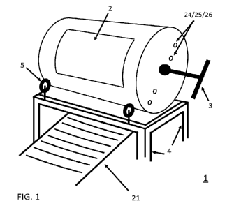
[0024] FIG. 1 illustrates a perspective view of a covered cavity kiln.
[0025] FIG. 2 illustrates a profile view of a functioning pyrolyzer of the
invention.
[0026] FIG. 3 is a cross-section illustrating pipes and sensors as inserted
into the kiln of the
invention.
[0027] FIG. 4A illustrates a cross-section view of a configuration of prongs
of an embodiment of
the invention.
[0028] FIG. 4B illustrates a cross-section view of a configuration of prongs
of an embodiment of
the invention.
[0029] FIG. 4C illustrates a cross-section view of a configuration of prongs
of an embodiment of
the invention.
[0030] FIG. 5 illustrates the portal positions on a cylindrical covered cavity
kiln
[0031] FIG. 6 illustrates prong positions at the portal when rotation is
clockwise versus
counterclockwise
[0032] FIGS. 7 and 8 illustrate profile views of an additional embodiment of
the invention.
[0033] FIG. 9 illustrates a perspective view of an additional embodiment of
the invention
100341 FIGS. 10-12 illustrate perspective views of an additional embodiment of
the invention.
[0035] FIG. 13 illustrates a perspective view of an additional embodiment of
the invention.
[0036] FIG. 14 illustrates a perspective view of an additional embodiment of
the invention.
9
CA 03165690 2022- 7- 21
WO 2021/150274
PCT/US2020/048013
DETAILED DESCRIPTION OF THE INVENTION
100371 The present invention is described in reference to the accompanying
drawings and
following embodiments that are presented for the purpose of illustration and
should not be
construed to limit the scope of the invention thereto.
100381 One embodiment of the present invention, as shown in FIGS. 1-2,
provides a covered cavity
kiln pyrolyzer 1, comprising an enclosure haying a first end surface and a
second end surface
joined by a continuous sidewall; the enclosure forming an interior area of the
pyrolyzer in which
entry of oxygen is regulated or prevented. Introduction of air is facilitated
via at least one portal 2,
such as an opening or a door, or regulated through a plurality of pipes 24.
100391 The covered cavity kiln pyrolyzer 1 further comprises at least one
portal 2 disposed along
the continuous sidewall of the cylinder, spanning an axis thereof except for
an area near each end
of the at least one portal 2 to aid the structural strength of the pyrolyzer 1
The area near each end
of the at least one portal 2 is further configured to engage a plurality of
roller wheels 5, the plurality
of roller wheels configured to make contact with and moveably couple the
continuous sidewall.
The at least one portal area may be divided into two or more segments,
allowing for separation
between an entry of air or fuel and an exit of emissions and flames. Some
embodiments of the
pyrolizer may further comprise a door that can cover some or all of the at
least one portal opening,
allowing for variable closure thereof.
100401 The two or more segments may further comprise a plurality of separate
holes specifically
located and configured to match positions of a plurality of chimneys 8, the
plurality of chimneys
comprising one or more free-standing structures capable of covering an area
relatively equal to an
area formed by a portal of the pyrolizer.
CA 03165690 2022- 7- 21
WO 2021/150274
PCT/US2020/048013
100411 The plurality of chimneys is further configured to redirect gases that
are expelled from the
pyrolizer during use. The plurality of chimneys may further comprise an
attached hood structure
7, the hood structure comprising a metal sheet supported from above or to a
side of the pyrolyzer
by a frame IL The frame of the hood structure may be coupled to, or wholly
separate from the
rack 4 upon which the cylinder of the pyrolyzer rests. The hood structure 7
may also be suspended
from above or at an angle to collect expelled gases. The hood structure 7 may
further comprise at
least one pleated or curved surface, such as domed spaces or channels, the at
least one pleated or
curved surface configured to help reduce any impact from crosswinds and to
further direct any
flaming emissions and expelled gases to the plurality of chimneys.
100421 The covered cavity kiln pyrolyzer 1 further comprises a cylindrical
container with at least
two closed ends, configured in a horizontal or inclined position. The
plurality of roller wheels 5 of
the covered cavity kiln pyrolyzer 1 may comprise a heat-resistant material,
with the plurality of
roller wheels 5 affixed to a rack 4 or support. The plurality of rollers are
further configured to be
an appropriate size for efficient, rotatable coupling of the covered cavity
kiln pyrolyzer.
100431 At at least one end of the covered cavity kiln pyrolyzer 1, a plurality
of handles or
mechanical couplings 3 is disposed, configured for manual rotation and
stability of the kiln. The
plurality of handles or mechanical couplings may be further configured to
couple a mechanical
means of rotation of the kiln. In some embodiments, the pyrolyzer may also
comprise at least one
axle and wheel disposed at each end of the cylindrical container of the
invention. The at least one
axle and wheel is configured to rotate independently of the pyrolyzer, such
that the axle and wheel
facilitates transportation of the invention, both during use and while the
pyrolyzer is not actively
functioning.
11
CA 03165690 2022- 7- 21
WO 2021/150274
PCT/US2020/048013
100441 The hood structure 7 may be configured to extend beyond an area defined
by the pyrolyzer,
allowing for channeling of heat to desired locations, such as for pre-drying
of biomass that could
be entering on a fuel feeder shelf 12, horizontal or inclined to feed biomass
to the at least one
portal, or above the hood structure for drying thereupon. The hood structure
is further configured
to be repositionable, allowing sliding and rotating about the kiln's central
axis such that the hood
structure covers the at least one portal when in the "straight-up position" as
shown in FIG. 5, but
allows the portal to remain uncovered when the invention is in the 'bulk-fuel-
feeding' position,
allowing unobstructed passage and access through the portal and into an
interior of the pyrolyzer.
100451 In some embodiments of the invention, hot emissions may be collected by
the hood
structure 7, and then subsequently directed into the plurality of chimneys 8
and can be further
directed for various uses. Such directional control can be by natural draft or
by forced draft of
blowers, fans, or inducers.
100461 In some embodiments of the invention, when the charcoal and any ash or
brands are
discharged downward, the pyrolyzer may further comprise an inclined surface 21
or a collection
tray 22 disposed under the pyrolyzer to facilitate the collection of the
output.
100471 In some embodiments of the invention, one or more pipes 24, probes 25,
or sensors 26 may
be configured to enter the kiln via a plurality of openings, usually at one or
more ends of the
pyrolyzer 1. In some embodiments, the one or more pipes, probes, or sensors
may be inserted via
an end of the cylinder, while in other embodiments the one or more pipes,
probes, or sensors may
be inserted through the portal 2 or a plurality of openings 24/25/26 disposed
at an end of the
enclosure. These can deliver accelerants or decelerants to alter the pyrolytic
process inside the kiln,
or they can deliver additives, such as solids and granular or powdered
chemicals, for purposes such
as the enhancement of the nutritional properties of the charcoal for plants
and soil microbes. The
12
CA 03165690 2022- 7- 21
WO 2021/150274
PCT/US2020/048013
pipes can be for natural or forced flows, all of which may be controlled and
modulated by the
operator or system.
100481 In some embodiments of the invention, attached to the air pipes or on
other pipes or bars
25, there may be prongs disposed thereupon that can be used for stirring the
biomass by either
rotation of the pipe/bar or by push-pull or any motion. These prongs are
configured to facilitate
mixing and creating pockets for air control. The prongs may also have
different numbers and
spacing configurations according to the biomass in the cylinder.
100491 Pipes with securely attached prongs 23 may be configured, as shown in
FIG. 4, with
appropriate separations, within the interior of the pyrolyzer. The prongs may
further be disposed
along one or more edges of the at least one portal 2. The pipes are configured
to allow rotational
movement thereof, facilitated by one or more handles coupled to the outside of
the cylinder. The
pipes and securely attached prongs may further be configured to be locked into
desired positions.
The pipes may also be configured to allow the prongs to swing freely, as shown
in FIGS. 4 and 6,
thereby becoming pressed into position by any charcoal or biomass that shifts
upon them within
the interior of the pyrolyzer. Depending on the biomass and rotation of the
cylinder, the prongs are
configured to lift or shift the biomass and charcoal when rotated clockwise,
while also being
positioned away from the at least one portal 2 when rotated counterclockwise,
as shown in FIG. 6.
100501 The prongs can further be affixed in positions, thereby forming a
strainer-like structure
configured to prevent sizeable pieces of biomass such as "brands" that are not
yet fully pyrolyzed
from falling out when the portal is facing downward. This essentially
separates much of the
charcoal from the not-yet pyrolyzed biomass. An advantage of this is that the
retained brands can
remain in the cylinder and then relocate to a bottom of pyrolyzer interior,
where the retained brands
can serve as a subsequent starter biomass when additional biomass is added for
continual charcoal
13
CA 03165690 2022- 7- 21
WO 2021/150274
PCT/US2020/048013
production. While a user is inserting fuel into the pyrolyzer, the prongs can
be configured to freely
swing or may be locked in a position that leaves the at least one portal fully
open, allowing further
modulation of oxygen exposure by the user. The prongs may further comprise
hollow pipes to
allow the dispersal of air or extinguishers such as water or inert gases to
allow modulation of char
production. The prongs may also comprise or contain sensors for operational
monitoring of
temperatures at or near the at least one portal throughout the production
process.
100511 The enclosure of the pyrolyzer may further comprise a non-cylindrical
shape, such as a
square-sided enclosure having affixed end plates that allow for attachment of
a pivot point at a
center of the end plates, or disposed upon the surface thereof. The enclosure
of the pyrolyzer may
then be suspended from the pivot points, with sufficient clearance to allow
outer edges of the
enclosure to maintain clearance for full rotational movement.
100521 In some embodiments, as shown in FIGS. 7-9 the invention may further
comprise a brace
structure 30 coupled to at least one end of the enclosure 1, the brace
structure 30 configured to
allow deployment, conveyance, and operation of the pyrolyzer. The brace
structure 30 may be
coupled to the enclosure such that the enclosure is articulated through the
movement of the brace
structure. The brace structure 30 may further be configured in a polygonal
shape comprised of at
least one linear member 32, the at least one linear member 32 configured to
moveably engage a
substantially flat surface, such that the linear member 32 is parallel with
said surface, thereby
creating a rotational stop for the pyrolyzer.
100531 One or more linear members 32 may further form a handle member,
allowing articulation
of the pyrolyzer during operation or transportation of the invention. In other
embodiments, at least
one brace structure, coupled at a first end of the enclosure, may be coupled
to at least one brace
14
CA 03165690 2022- 7- 21
WO 2021/150274
PCT/US2020/048013
structure coupled at a second end of the enclosure, both brace structures
coupled by at least one
cross member 34.
100541 In some embodiments, the cross member 34 of the brace structure may
further comprise an
articulable flap, forming prongs 23. In other embodiments, the cross member 34
of the brace
structure may further comprise an articulable flap, forming a hood structure
7. In other
embodiments, the cross member 34 is further coupled to a support bracket 38
configured to engage
and retain a hood structure, the hood structure being formed by an articulable
flap coupled to the
at least one portal 2 of the pyrolyzer. The hood structure 7 also further
comprises a plurality of
chimneys coupled to and disposed therethrough, configured to collect and
redirect gases expelled
from the pyrolizer enclosure during use. The hood structure 7, further
comprises a handle
configured to allow a user to hold the hood structure in place or to move the
hood structure during
operation of the pyrolyzer, such as any tipping of the invention. The
articulable flap further allows
for user-defined modulation of collection and redirection of expelled gases by
moving the
articulable flap and the plurality of chimneys through various positions,
dependent on a current
rotational orientation of the enclosure relative to a ground surface.
100551 In some embodiments, the brace structure 30 further comprises multiple
linear members
32, arranged in a polygonal shape in which each linear member corresponds to a
rotational angle
or state in which the enclosure can be retained. Each linear member 32 engages
a flat surface in a
parallel configuration, thereby halting any rotational movement of the
enclosure, allowing further
rotation of the enclosure through articulation of the brace structure until
another linear member 32
engages a flat surface and momentarily halts further rotational movement.
Rotation of the
enclosure of these embodiments, as well as mixing of any contents thereof, is
accomplished
through movement of the brace structure, either by tipping or complete lifting
and transposing by
CA 03165690 2022- 7- 21
WO 2021/150274
PCT/US2020/048013
a user. Further, the brace member may further comprise a plurality of
attachment points on each
end of the enclosure, configured to allow modulation of linear members,
thereby allowing
modulation of rotational capabilities of the invention by adding or removing
linear members 32 or
modifying the overall shape of the brace structure.
100561 The covered cavity kiln pyrolyzer may be further constructed inside of
an appropriately
sized building or container that could obviate the need for a rack or a frame
or a hood structure.
The individual components of the invention may derive structural support from
other freestanding
structures, as well as derive gas and heat collection or redirection from
other freestanding systems
designed for such collection or redirection.
[0057] The prongs may further comprise a grate or screen coupled to the at
least one portal by an
operator for facilitating screening or sifting processes. The grate or screen
need not be coupled to
the at least one portal throughout any rotational movements of the pyrolizer.
Additionally, in some
embodiments, at least one door may be disposed over the at least one portal by
an operator to
enclose the kiln such as for rotation without char discharge or to maximize
emissions for chemical
recovery such as condensates. While the at least one door is disposed over the
at least one portal,
the pyrolizer is not pressurized, having at least one exit for any expelled
gases. During such
operation, the pyrolyzer is configured to allow controlled entry of limited
air into the interior of
the enclosure and throughout an enclosure biomass to provide sufficient flames
to maintain desired
pyrolytic temperatures. The at least one door is further configured to allow
opening as needed for
refueling and for discharge of generated charcoal.
100581 The kiln may be either portable or configured to operate in fixed
positions. In other
embodiments, the kiln further comprises detachable wheels or skids configured
to allow
transportation of the kiln. The kiln may further be supported by an adjustable
frame to allow
16
CA 03165690 2022- 7- 21
WO 2021/150274
PCT/US2020/048013
inclination at various angles by raising or lowering one or more ends of the
cylinder to cause any
contents to shift toward one end. This movement would allow for additional
shifting of the contents
from one end toward another, especially if rotated while inclined This allows
a high degree of fuel
feeding to be done near one end and most charcoal removal to be performed at
the other end,
including the possible charcoal removal through a plurality of openings in one
or more ends of the
kiln.
100591 The pyrolyzer may also comprise one or more fuel delivery mechanisms
coupled thereto
and configured to facilitate transportation of biomass into an interior of the
kiln. In some
embodiments, a hopper containing fuel biomass may be suspended above the
pyrolyzer and
configured to dispense quantities of the fuel biomass into the enclosure.
Dispersion of the fuel
biomass may be automated or initiated through operation by a user. In some
embodiments, the
pyrolyzer comprises a feeder shelf 12 configured such that fuel entry and the
dispensing or outflow
of the charcoal may be automated or facilitated by a user.
100601 In another embodiment of the invention, shown in FIGS. 10-12, the at
least one axle and
wheel 42 of the pyrolyzer is configured to rotate as one structure, forming a
main axle. The main
axle is further movably coupled to the frame member 4. In such embodiments,
the frame member
4 also comprises at least one handle structure 44, configured to allow
movement of the enclosure
through rotation of the main axle. A wheel of the main axle engages a ground
surface, allowing
for ease of movement of the overall invention by a user. Further, the frame
member 4 is configured
to form the feeder shelf (not shown) of the invention, such that rotation of
the frame member 4
about the main axle also rotates the feeder shelf about the main axle. In
other embodiments, the
feeder shelf may be coupled to a top side of the frame member 4, such that the
frame member and
the feeder shelf are parallel and within the same relative plane. In such
embodiments, biomass
17
CA 03165690 2022- 7- 21
WO 2021/150274
PCT/US2020/048013
placed on the feeder shelf may be loaded into the enclosure by lifting the
frame member 4, via the
at least one handle structure 44, forming a sloped surface by which the
biomass will slide along
and into the enclosure.
100611 In another embodiment of the invention, the main axle may be partially
rotationally locked,
such that the enclosure 1 is prevented from rotation, while at least one axle
and wheel 42 of the
main axle may still rotate about the main axle, causing rotational mixing
within the enclosure 1.
The at least one axle and wheel 42 allows for continued movement of the
invention, while still
allowing for independent functions of the enclosure 1, such as loading or
unloading, to be carried
out by a user. The enclosure 1 is further configured such that it may rotate
independently of the at
least one axle and wheel 42, while still forming the main axle of the
invention. In other
embodiments, the enclosure 1 is further configured to move in a limited
capacity away from a
central axis of the main axle, along a plane formed by the frame member 4.
Movement of the
enclosure along the plane of the frame member 4 is configured to facilitate
loading and mixing
operations of the invention.
100621 Further, the frame member 4 comprises an integrated hood structure 7
suspended above,
and independent of, the enclosure through a plurality of elongate members
extended from the
frame member and coupled to the integrated hood structure 7. The integrated
hood structure
comprises a plurality of chimneys 8 to allow collection and redirection of
expelled gases allowing
controlled expulsion of gases from the enclosure. The integrated plurality of
chimneys 8 are further
configured to couple an additional hood structure 7 with a plurality of
chimneys 8, allowing for
greater control of expelled gases.
100631 In another embodiment of the invention, shown in FIG. 13, the frame
member may be
configured as a plurality of rails 50, placed on a ground surface, and further
configured to
18
CA 03165690 2022- 7- 21
WO 2021/150274
PCT/US2020/048013
moveably engage the pyrolyzer enclosure 1. At a first end of the plurality of
rails 50, at least one
hood support 52 is disposed and coupled to the plurality of rails 50. The at
least one hood support
comprises an upright member moveably coupled to the hood structure 7 of the
invention; the hood
structure further comprising a plurality of chimneys 8 disposed upon and
therethrough.
100641 In some embodiments of the invention, the hood structure 7 further
comprises more than
one hood section, each hood section being moveably coupled to a different
upright member. Each
hood section is further configured to rotatably couple the upright member,
such that each hood
section is capable of rotating about an axis of the upright member, allowing a
user to move the
hood section into various positions while in use.
100651 The enclosure 1 of the invention is configured to roll along a plane
formed by the plurality
of rails 50, such that the enclosure rotates through various operational
positions while al so moving
along a length of the plurality of rails. At an end of the plurality of rails,
the pyrolyzer further
comprises a receptacle 54 disposed under the plane of the plurality of rails,
either within a hole in
a ground surface or wherein the plurality of rails is suspended above the
receptacle. The receptacle
54 is configured to accept discharged char from the at least one portal of the
enclosure, such that
a linear position of the portal relative to a rotational position of the
portal aligns with the position
of the receptacle along the plane of the plurality of rails.
100661 In some embodiments of the invention, shown in FIG. 14, the enclosure 1
and the plurality
of rails 50 may be enclosed in a hyper-hood 60 configured to collect and
retain any and all fumes,
expelled gases, or other emissions from the process of using the invention.
The hyper-hood 60 may
further be equipped with an air filtration system, either active or passive,
in order to control overall
emissions by the invention. In some embodiments of the invention, the hyper-
hood 60 also
comprises a hood structure 7 and plurality of chimneys 8 disposed upon a top
surface thereof; the
19
CA 03165690 2022- 7- 21
WO 2021/150274
PCT/US2020/048013
hood structure and plurality of chimneys being configured to align with the
portal of the enclosure
in order to collect and retain any fumes, expelled gases, and other emissions
from the pyrolyzer
during operation thereof.
100671 The covered cavity kiln operates with the combustion of pyrolytic gases
providing the heat
to sustain the pyrolysis of the biomass in the pyrolyzer. Operator preferences
and characteristics
of some types of biomass could lead to different procedures as needed for the
type or quantity of
biomass.
100681 The covered cavity kiln of the invention comprises six different
designated positions of
operation, as shown in FIGS. 5A-F. Each position of operation may be
identified by a radial
position of the portal about a central axis of the cylinder, expressed in
degrees on a circle,
increasing clockwise for 0 and 360 degrees at the top position. The at least
one portal in this
example is 80 degrees of arch. The degrees are with some approximation and
need not be measured
or determined with accuracy on the kiln, as they are merely reference points
for the positions of
operation.
Portal position Position Name Purpose Observations
5A 270 to 350 Shelf fuel feeding Slide in fuel on shelf "Normal"
position; best flame cap.
5B 320 to 40 Straight up under hood Slow the fire Least
air entry: -simmer".
5C 10 to 90 Bulk fuel feeding Open access w/o hood Short time
only; lacks draft.
5D 140 to 220 Straight down Unloading Used sparingly.
5E Roll 240 Rocking back and forth Tumble w/o dumping
Use common sense; vanes w/ fuel type.
5F Roll 360+ Full rotation Mixing extensively Subject to
conditional limitations.
100691 When the kiln and the fuel are all cold, the kiln is positioned in a
fuel feeding position,
shown in 5A, 5B, and 5C. Then, a modest layer of cold charcoal is added as
fuel into the kiln to
minimize any failure of pyrolysis to reach the lowest levels that are touching
the cold steel.
Feedstock is added next, the feedstock configured to ignite an even fire
across the entire bed of the
kiln. The fire is then ignited and established with placement of additional
fuel.
CA 03165690 2022- 7- 21
WO 2021/150274
PCT/US2020/048013
100701 Next, a user initiates slow rotation of the kiln until the kiln is in
the "normal" or shelf fuel
feeding position of operation 5A. Fuel is then added as needed. This method of
operation allows
faster and larger quantities of char production than with typical open-top
flame-cap (open cavity)
kilns due to a user of the current invention retaining the ability to mix the
contents to attain
complete pyrolysis.
100711 When an accumulated biomass and charcoal has amassed within the lower
portion of the
kiln and has not fully pyrolyzed, the cylinder is then rotated back and forth
between 5E on the
support wheels or central axis of the pyrolyzer, causing the biomass to shift
position and expose
the non-pyrolyzed material to heat for pyrolysis Rotation will also break
apart the pieces of
charcoal. Movement of the prongs, flights, lifters and pipes can also assist
to expose any non-
pyrolyzed material to the heat. Varied and modulated movement and fuel
additions continue until
a lower half of the kiln is full of charcoal.
100721 When the prongs are positioned to extend across the at least one
portal, this allows char to
be removed through the gaps while securing inside the container most of the
biomass that has not
yet been completely pyrolyzed. In this situation, the cylinder can be rotated
fully and continuously
or with rotations in opposite directions, with exit of charcoal when in the
straight down position
5D, facilitated by the prongs.
100731 To continue making charcoal, a small amount of hot char is retained
(and any biomass that
is still pyrolyzing, perhaps intentionally added a few minutes before
extracting the charcoal) to
avoid needing the sensitive ignition stage previously discussed. Rotating the
pyrolyzer back to
either of the two positions for loading in more fuel and then continuing to
the normal position 5A.
21
CA 03165690 2022- 7- 21
WO 2021/150274
PCT/US2020/048013
100741 To completely empty the pyrolyzer, the prongs are positioned away from
closing the at
least one portal so that the contents can be totally emptied downward by
gravity. To reduce the
occurrence of rusting, do not wash the covered cavity kiln.
100751 Those of ordinary skill in the art will understand and appreciate that
the foregoing
description of the invention has been made with reference to certain exemplary
embodiments of
the invention, which describe a covered cavity kiln pyrolyzer. Those of skill
in the art will
understand that obvious variations in system configuration, protocols,
parameters or properties
may be made without departing from the scope of the invention which is
intended to be limited
only by the claims appended hereto.
22
CA 03165690 2022- 7- 21