Note: Descriptions are shown in the official language in which they were submitted.
CA 03166561 2022-06-30
WO 2021/150162 PCT/SE2021/050034
1
SET OF PANELS WITH A MECHANICAL LOCKING DEVICE
Technical field of the invention
Embodiments of the present invention relate to panels configured to be locked
together with a mechanical locking device. The panels may be assembled and
locked together to obtain a furniture product, such as a bookshelf, a
cupboard, a
wardrobe, a box, a drawer or a furniture component.
Technical Background
A furniture product provided with a mechanical locking is disclosed in
PCT/SE2019/050801 or PCT/SE2019/050802. The furniture products earlier
described comprise a first panel connected perpendicular to a second panel by
a
mechanical locking device comprising a rod-shaped element extending at an
angle.
The above description of various known aspects is the applicant's
characterization
of such, and is not an admission that any of the above description is
considered
as prior art.
Embodiments of the present invention address a need to provide panels that may
be easily assembled, having an improved stiffness and strength of the
mechanical
locking device.
Summary of the invention
It is an object of certain aspects of the present invention to provide an
improvement over the above described techniques and known art. A specific
objective is to improve assembling of panels, such as furniture panels, locked
together by a mechanical locking device. The panels may be a part of a
furniture
product, such as a furniture component, a drawer, a cupboard, a bookshelf, a
wardrobe, a kitchen fixture, or a box.
A further object of at least certain aspects of the present invention is to
facilitate
assembling of panels configured to be assembled with a locking device that is
easy to manufacture and to use.
CA 03166561 2022-06-30
WO 2021/150162 PCT/SE2021/050034
2
A further object of at least certain aspects of the present invention is to
facilitate
assembling of panels configured to be assembled with a locking device that is
easy to manufacture and to use and which reduces the risk of incorrect
installation
thereof.
A further object of at least certain aspects of the present invention is to
facilitate
assembling of panels configured to be assembled in a more stable and aesthetic
way.
At least some of these and other objects and advantages that will be apparent
from the description have been achieved by a set comprising a first panel, a
second panel and a mechanical locking device for locking the first panel to
the
second panel, wherein the first panel comprises a first edge surface and a
second
panel surface, the second panel comprises a second panel surface, the first
edge
surface is facing the second panel surface in a locked position of the first
and the
second panel, the mechanical locking device comprises at least one rod-shaped
element at the first edge surface and at least one insertion groove at the
second
panel surface, the rod-shaped element is configured to be inserted into the
insertion groove, the mechanical locking device further comprises at least one
first
locking groove at the first edge surface and at least one second locking
groove at
the second panel surface and at least one locking part, the locking part is
configured to be inserted into the first locking groove and the second locking
groove, wherein the locking part is configured to apply a locking force
between the
first and the second panel in an oblique direction in relation to the second
panel
surface.
According to an aspect the oblique direction is at an acute angle to the
second
panel surface.
According to an aspect the set is configured for locking the first panel to
the second
panel with the first panel surface perpendicular or essentially perpendicular
to the
second panel surface.
According to an aspect the locking part is configured to pull the first panel
and the
second panel together in an assembly direction.
CA 03166561 2022-06-30
WO 2021/150162 PCT/SE2021/050034
3
According to an aspect the oblique direction is essentially parallel to a
length
direction and/or axial direction of the rod-shaped element.
According to an aspect the rod-shaped element is configured to cooperate with
the insertion groove to guide the first and second panel together during
assembly.
According to an aspect the rod-shaped element is configured to cooperate with
insertion groove to guide the first and second panel to the locked position by
a
displacement of the second panel surface relative the first edge surface in a
first
direction and/or a second direction.
According to an aspect the rod-shaped element extends at a first angle from
the
first edge surface, wherein the first angle is within the range of about 100
to 800
,
preferably within the range of about 400 to 500, or preferably about 45 .
According to an aspect the insertion groove extends into the second panel
surface
at a second angle from the second panel surface, wherein the second angle is
within the range of about 10 to 80 , preferably within the range of about 400
to
50 , or preferably about 45 .
According to an aspect said first locking groove extends at a third angle from
the
first edge surface, wherein the third angle is within the range of about 100
to 80 ,
preferably within the range of about 40 to 50 , or preferably about 450
.
According to an aspect said second locking groove extends at a fourth angle
from
the second panel surface, wherein the fourth angle is within the range of
about
10 to 80 , preferably within the range of about 40 to 50 , or preferably
about 450
.
According to an aspect the first angle, the second angle, the third angle and
the
fourth angle are essentially the same. For example, the first angle, the
second
angle, the third angle and the fourth angle may be within 2 of each other.
Further,
the first angle, the second angle, the third angle and the fourth angle may be
the
same.
According to an aspect the first angle, the second angle, the third angle and
the
fourth angle are all # 90 .
According to an aspect the locking part is a screw.
CA 03166561 2022-06-30
WO 2021/150162 PCT/SE2021/050034
4
According to an aspect the screw extends into the second panel during
assembly.
According to an aspect the first locking groove extends from a second edge
surface to the first edge surface.
According to an aspect the locking part is of the type cam and dowel
connector.
According to an aspect the cam and dowel connector comprises at least one bolt
and at least one connector housing.
According to an aspect the bolt of the cam and dowel connector is positioned
in
the first locking groove before assembly of the first panel and the second
panel.
According to an aspect the connector housing is positioned in a first opening
on
the first panel.
According to an aspect the set comprises a first panel groove on a first panel
surface of the first panel, and a second panel groove on the second panel
surface
of the second panel.
According to an aspect the set further comprises a back panel configured to be
inserted in, and optionally to cooperate with, the first and second panel
groove.
According to an aspect the first opening is positioned between the first panel
groove and the second edge surface.
According to an aspect the insertion groove, the first locking groove, the
second
locking groove and/or the first opening is a drill hole.
According to an aspect the drill hole is a bottom-ended drill hole.
According to an aspect the locking part is configured to cooperate with the
first
locking groove and/or the second locking groove.
According to an aspect the first edge surface comprises one first locking
groove
and the second panel surface comprises one second locking groove.
According to an aspect the rod-shaped element is arranged in a rod-element
groove at the first edge surface.
CA 03166561 2022-06-30
WO 2021/150162 PCT/SE2021/050034
According to an aspect the number of rod-shaped elements at the first edge
surface is the same as the number of insertion grooves at the second panel
surface.
According to an aspect the core of the first panel and/or of the second panel
may
5 be a wood-based core, preferably made of MDF, HDF, OSB, WPC, plywood or
particleboard. The core may also be a plastic core comprising thermosetting
plastic or thermoplastic, e.g., vinyl, PVC, PU or PET. The plastic core may
comprise fillers.
The first panel and/or the second panel may also be of solid wood.
The first panel and/or the second panel may be provided with a decorative
layer,
such as a foil or a veneer, on one or more surfaces.
Brief Description of the Drawings
These and other aspects, features and advantages of which embodiments of the
invention are capable of, will be apparent and elucidated from the following
description of embodiments and aspects of the present invention, reference
being
made to the accompanying drawings, in which
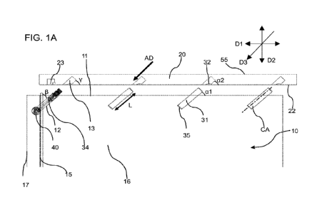
FIG. 1A shows an embodiment of the first panel and the second panel in a side-
view in a non-locked position. The locking part is of the type cam and dowel
connector.
FIG. 1B shows an embodiment of the first panel and the second panel in a side-
view in a non-locked position. The locking part is a screw.
FIG. 2A shows an embodiment of the first panel and the second panel in a side-
view in a non-locked position.
FIG. 2B shows an embodiment of the first panel and the second panel in a side-
view in a locked position. The locking part is a screw.
FIG. 3 shows an embodiment of the first panel and the second panel in a side-
view in a locked position. The locking part is of the type cam and dowel
connector.
FIGS. 4A-4B show an embodiment of the first and the second panel in a side-
view
in a non-locked position and in a locked position. The locking part is of the
type
cam and dowel connector.
CA 03166561 2022-06-30
WO 2021/150162 PCT/SE2021/050034
6
FIG. 5A shows an enlargement of part of the embodiment shown in FIG. 3. The
locking part is of the type cam and dowel connector.
FIG. 5B shows the part in FIG 5A in a side-view.
FIG. 5C shows an enlarged side-view of a part of an embodiment of the
invention.
FIG. 6A-6B show embodiments of the first and second panel in a 3D-view in a
non-locked position.
FIGS. 7A-7B show different 3D-views of an embodiment of a set of panels
according to the invention in an assembled state.
Detailed Description
Specific embodiments of the invention will now be described with reference to
the accompanying drawings. This invention may, however, be embodied in many
different forms and should not be construed as limited to the embodiments set
forth herein; rather, these embodiments are provided so that this disclosure
will
be thorough and complete, and will fully convey the scope of the invention to
those skilled in the art. The terminology used in the detailed description of
the
embodiments illustrated in the accompanying drawings is not intended to be
limiting of the invention. In the drawings, like numbers refer to like
elements.
The terminology used herein is for the purpose of describing particular
aspects
of the disclosure only, and is not intended to limit the disclosure. As used
herein,
the singular forms "a", "an" and "the" are intended to include the plural
forms as
well, unless the context clearly indicates otherwise.
In the drawings and specification, there have been disclosed exemplary aspects
of the disclosure. However, many variations and modifications may be made to
these aspects without substantially departing from the principles of the
present
disclosure. Thus, the disclosure should be regarded as illustrative rather
than
restrictive, and not as being limited to the particular aspects discussed
above.
Accordingly, although specific terms are employed, they are used in a generic
and descriptive sense only and not for purposes of limitation, for example,
definition of dimensions such as width or breadth or height or length or
diameter
depends on how exemplary aspects are depicted, hence, if depicted differently,
a shown width or diameter in one depiction is a length or thickness in another
CA 03166561 2022-06-30
WO 2021/150162 PCT/SE2021/050034
7
depiction.
It should be noted that the word "comprising" does not necessarily exclude the
presence of other elements or steps than those listed and the words "a" or
"an"
preceding an element do not exclude the presence of a plurality of such
elements. It should further be noted that any reference signs do not limit the
scope of the claims, that the example aspects may be implemented at least in
part by means of both hardware and software, and that several "means", "units"
or "devices" may be represented by the same item of hardware.
The different aspects, alternatives and embodiments of the invention disclosed
herein may be combined with one or more of the other aspects, alternatives and
embodiments described herein. Two or more aspects may be combined.
Embodiments of the invention are shown in FIGS 1-6 including a set comprising
a
first panel 10, a second panel 20 and a mechanical locking device for locking
of
the first panel 10 to the second panel 20. The first panel 10 comprises a
first panel
surface 16 and a first edge surface 11. The second panel 20 comprises a second
panel surface 22. The first edge surface 11 is facing the second panel surface
22
in a locked position of the first and the second panel 10,20. The mechanical
locking device comprises at least one rod-shaped element 31 at the first edge
surface 11 and at least one insertion groove 32 at the second panel surface
22.
The rod-shaped element 31 is configured to be inserted into the insertion
groove
32. The mechanical locking device further comprises at least one first locking
groove 12 at the first edge surface 11 and at least one second locking groove
13
at the second panel surface 22 and at least one locking part 34. The locking
part
34 is configured to be inserted into the first locking groove 12 and the
second
locking groove 13. The locking part 34 is configured to apply a locking force
between the first and the second panel 10,20 in an oblique direction D3 in
relation
to the second panel surface 22. The locking force at least acts to prevent
separation of the first panel from the second panel.
The oblique direction D3 may be at an acute angle to the second panel surface
22.
The first panel 10 and the second panel 20 are preferably panels for a
furniture
product and may be a part of a frame of a furniture product.
CA 03166561 2022-06-30
WO 2021/150162 PCT/SE2021/050034
8
The set is preferably configured for locking the first panel 10 to the second
panel
20 with the first panel surface 16 perpendicular or essentially perpendicular
to the
second panel surface 22.
The first panel 10 may comprise a third panel surface 54 which is opposite to
the
.. first panel surface 16. The second panel 20 may comprise a fourth panel
surface
55 which is opposite to the second panel surface 22.
The first panel surface 16 preferably meets the second panel surface 22 in a
locked position of the first panel 10 and the second panel 20.
The first panel surface 16 preferably meets the second panel surface 22 at an
inner corner of the assembled set.
Fig. 1-2A, 4A, 6A, and 6B disclose a set according to an aspect in an
unassembled
state. The set may be assembled by displacing the first panel 10 relative the
second panel 20 in an assembly direction AD. Fig 2B, 3, 4B, and 5A-5C disclose
a set according to an aspect in an assembled state.
The locking part 34 may be configured to pull the first 10 and the second
panel 20
together in the assembly direction AD.
The oblique direction D3 may be essentially parallel to a length direction L
and/or
axial direction CA of the rod-shaped element 31. For example, the oblique
direction D3 may be within 2 of the length direction L and/or axial direction
CA of
the rod-shaped element 31. Further, the oblique direction D3 may be parallel
to a
length direction L and/or axial direction CA of the rod-shaped element 31.
The rod-shaped element 31 may be configured to cooperate with the insertion
groove 32 to guide the first and second panel 10,20 together during assembly.
The rod-shaped element 31 may be configured to cooperate with the insertion
groove 32 to guide the first and second panel 10,20 to the locked position by
a
displacement of the second panel surface 22 relative the first edge surface 11
in
a first direction D1 and/or a second direction D2.
The rod-shaped element 31 may extend at a first angle al from the first edge
surface 11, wherein the first angle al is within the range of about 10 to 80
,
preferably within the range of about 40 to 50 , or preferably about 45 .
CA 03166561 2022-06-30
WO 2021/150162 PCT/SE2021/050034
9
The rod-shaped element 31 may be arranged in a rod-element groove 35 at the
first edge surface 11.
The number of rod-shaped elements 31 at the first edge surface 11 may be the
same as the number of insertion grooves 32 at the second panel surface 22.
The rod-shaped element 31 may have a waxed surface to facilitate assembly.
According to an aspect the rod-shaped element 31 may be configured to be
attached in the rod element groove 35 by friction.
According to an aspect the rod-shaped element 31 may be configured to be glued
in the rod element groove 35.
According to an aspect the rod-shaped element 31, the rod element groove 35
and the insertion groove 32 have a substantially circular shape, although
other
shapes, such as triangular, rectangular, square, etc. are possible. When the
rod-
shaped element has a circular shape, the length direction L and axial
direction CA
of the rod-shaped element 31 is the same.
According to an aspect the rod-shaped element 31 is made from one or more of
a wood-based material, a polymer material, preferably with an enforcement,
such as glass fibre or a metal.
The sidewalls of the insertion groove 32, the locking groove 35, the first
locking
groove (12) and the second locking groove (13) may comprise material of the
core
of the first panel 10 or the second panel 20, dependent on in which panel they
are
made. According to an aspect the sidewalls may also be enforced with, e.g.,
plastic material, such as a thermoplastic material, metal and/or glass fibre.
The first edge surface 11 may comprise one or more of said rod-shaped element
31 and the second panel surface 22 may comprise one or more of said insertion
groove 32, and vice versa. Three or more of said rod-shaped element and said
insertion groove 32 may be arranged linearly, wherein each of the rod-shaped
elements 31 is configured to be inserted into one of said insertion groove 32.
The insertion groove 32 may extend into the second panel surface 22 at a
second
angle a2 from the second panel surface 22, wherein the second angle a2 is
within
CA 03166561 2022-06-30
WO 2021/150162 PCT/SE2021/050034
the range of about 100 to 800, preferably within the range of about 400 to 50
, or
preferably about 45 .
The first locking groove 12 may extend at a third angle p from the first edge
surface
11, wherein the third angle p is within the range of about 100 to 80 ,
preferably
5 within the range of about 40 to 50 , or preferably about 45 .
The second locking groove 13 may extend at a fourth angle y from the second
panel surface 22, wherein the fourth angle y is within the range of about 10
to
80 , preferably within the range of about 40 to 50 , or preferably about 45 .
The first angle al, the second angle a2, the third angle p and the fourth
angle y
10 may be essentially the same. For example, the first angle, the second
angle, the
third angle and the fourth angle may be within 2 of each other. Further, the
first
angle, the second angle, the third angle and the fourth angle may be the same.
The first angle al, the second angle a2, the third angle p and the fourth
angle y
may all be # 90 .
In one embodiment, as shown in FIGS. 1B and 2B, the locking part 34 is a
screw.
The screw may extend into the second panel 20 during assembly.
The second locking groove 13 at the second panel surface 22 does not have to
be a groove or drill hole as wide as the locking part 34 and/or as deep as the
intended extent of the locking part 34 into the second panel, but may be,
e.g., a
small recess or the like, which may guide the locking part 34 into a correct
place,
especially for the embodiment where the locking part is a screw.
The first locking groove 12 may extend from a second edge surface 17 to the
first
edge surface 11.
In one embodiment, as shown in FIGS. 1A, 3, and 4A-5C, the locking part 34 is
of
the type cam and dowel connector. The cam and dowel connector may comprise
at least one connecting element 51, such as a bolt, and at least one connector
housing 52.
The cam and dowel connector may comprise an expanding part 56. The
expanding part 56 is configured to expand in the second locking groove 13 such
that the expanding part 56 is attached to the second locking groove 13. The
CA 03166561 2022-06-30
WO 2021/150162 PCT/SE2021/050034
11
connecting element 51 may extend from the connector housing 52 to the
expanding part 56.
The connector housing 52 may be positioned in a first opening 40 on the first
panel
10.
The bolt 51 of the cam and dowel connector may be positioned in the first
locking
groove 12 before assembly of the first panel 10 and the second panel 20, which
is shown in the embodiments in FIGS. 1A and 4A.
Cam and dowel connectors are known in the art of assembly of furniture. The
cam
may be a cylindrical lock with an opening for the dowel. The cam/connector
housing, which does the latching, may be actuated by rotary motion, typically
through 90 or 180 degrees, with rotating excentres or wedges acting on a head
of
the dowel. The dowel is typically a bolt, pin or screw.
Cam and dowel connector, when actuated pulls the second panel surface 22
relative the first edge surface 11 in the first direction D1 and the rod-
shaped
element 31 may be configured to cooperate with the insertion groove 32 to lock
the first and the second panel 10,20 in the second direction D2. This may have
the advantage of enabling optional placement of the locking part 34 along the
panel edge 11, preferably in a less visible location on an assembled
furniture.
Furthermore, only one locking part 34 may be used to lock the first and second
panel and still have a strong locking along the whole panel edge of the first
and
second panel 10,20 which may include one or more rod-shaped elements 31.
As shown, e.g., in FIGS. 1A-2A and 6A, the set may comprise a first panel
groove
15 on a first panel surface 16 of the first panel 10, and a second panel
groove 23
on the second panel surface 22 of the second panel 20. The set may further
comprise a back panel 30 configured to be inserted in, and optionally to
cooperate
with, the first and second panel groove 15, 23.
The first opening 40 may be positioned between the panel groove 15 and the
second edge surface 17, as, e.g., is shown in FIGS. 1A, 3 and 5A. This gives
an
aesthetic result since the locking device is no longer visible after assembly
of the
panels, but is hidden behind the back panel 30 if a back panel 30 is present.
CA 03166561 2022-06-30
WO 2021/150162 PCT/SE2021/050034
12
FIG 5B shows that the locking groove 12 may be positioned under the panel
groove 15. The first panel 10 may comprise a third panel surface 54 which is
opposite to the first panel surface 16. The locking groove may be positioned
between a bottom surface 53 of the panel groove 15 and the third panel
surface.
FIG 5C shows in a side-view an enlarged part of an embodiment of the set. In
this
embodiment the first opening 40 may be positioned in the second edge surface
17 of the first panel 10.
The first opening 40 may be in a position that will not be hidden by a back
panel
30, as shown in FIGS. 4A-4B, which show an embodiment with the first and
second panel 10,20 in a non-locked and a locked position. Thus, the first
opening
40, and, e.g., the cam inserted therein, might be visible.
The insertion groove 32, the first locking groove 12, the second locking
groove 13
and/or the first opening 40 may be a drill hole. The drill-holes may be bottom-
ended drill holes.
The locking part 34 may be configured to cooperate with the first locking
groove
12 and/or the second locking groove 13. For example, the locking part 34 may
engage with the sidewalls of the first locking groove and/or the sidewall of
the
second locking groove to create a pulling force in the second direction D2. In
an
embodiment, the locking part 34 may engage with the sidewall of the second
locking groove, but not the sidewall of the first locking groove, to create a
pulling
force in the second direction D2. This gives a strong locking of the first
panel 10
to the second panel 20.
In one embodiment, the first edge surface 11 may have one first locking groove
12 and the second panel surface may have one second locking groove 13.
According to this embodiment, only one locking part 34 is necessary for
locking of
the first panel 10 to the second panel 20.
According to an aspect the first panel 10 and the second panel 20 may be
assembled by displacing the first panel 10 relative the second panel 20 in a
direction which is essentially parallel with the second panel surface 22. The
last
part of the assembly may be in a direction that is essentially parallel to at
least one
of the first angle al, the second angle a2, the third angle 13 and the fourth
angle y.
CA 03166561 2022-06-30
WO 2021/150162 PCT/SE2021/050034
13
FIGS. 7A-7B show 3D-views of an embodiment of the invention in a locked
position. The embodiment comprises two of said first panel 10 and two of said
second panel 20 which are assembled as a frame of, e.g., a furniture. The
embodiment further comprises a back panel 30 which is assembled to the frame.
The mechanical locking device is not visible from a side-view and/or a front-
view
when the panels are assembled, giving a very aesthetic result. Parts of the
mechanical locking device may be seen from a back-view of the embodiment.
The core of the first panel 10 and/or of the second panel 20 may be a wood-
based
core, preferably made of MDF, HDF, OSB, WPC, plywood or particleboard. The
core may also be a plastic core comprising thermosetting plastic or
thermoplastic,
e.g., vinyl, PVC, PU or PET. The plastic core may comprise fillers.
The first panel 10 and/or the second panel 20 may also be of solid wood.
The first panel 10 and/or the second panel 20 may be provided with a
decorative
layer, such as a foil or a veneer, on one or more surfaces.
According to an aspect the set of panels are resilient panels. The resilient
panels
may comprise a core comprising thermoplastic material. The thermoplastic
material may be foamed.
The thermoplastic material may comprise polyvinyl chloride (PVC), polyester,
polypropylene (PP), polyethylene (PE), polystyrene (PS), polyurethane (PU),
polyethylene terephthalate (PET), polyacrylate, methacrylate, polycarbonate,
polyvinyl butyral, polybutylene terephthalate, or a combination thereof. The
core
may be formed of several layers.
The aspects described above may comprise a decorative layer, such as a
decorative foil comprising a thermoplastic material. The thermoplastic
material of
the decorative layer may be or comprise polyvinyl chloride (PVC), polyester,
polypropylene (PP), polyethylene (PE), polystyrene (PS), polyurethane (PU),
polyethylene terephthalate (PET), polyacrylate, methacrylate, polycarbonate,
polyvinyl butyral, polybutylene terephthalate, or a combination thereof. The
decorative foil is preferably printed, for example by direct printing,
rotogravure, or
digital printing. According to an aspect the decorative layer comprises
melamine,
a high-pressure laminate (HPL) or a veneer.
CA 03166561 2022-06-30
WO 2021/150162 PCT/SE2021/050034
14
The aspects described above may comprise a wear layer such as a film or foil.
The wear layer may comprise thermoplastic material. The thermoplastic material
may be polyvinyl chloride (PVC), polyester, polypropylene (PP), polyethylene
(PE), polystyrene (PS), polyurethane (PU), polyethylene terephthalate (PET),
polyacrylate, methacrylate, polycarbonate, polyvinyl butyral, polybutylene
terephthalate, or a combination thereof.
The aspects described above may comprise a wood base core, such as HDF,
MDF, plywood, particleboard, OSB or Masonite.
The different aspects, embodiments and alternatives described above may be
combined with one or more of the other described aspects, embodiments and
alternatives.