Note: Descriptions are shown in the official language in which they were submitted.
WO 2021/158979
PCT/US2021/016902
SUPPORT FOR TEST DEVICE
CROSS-REFERENCE TO RELATED APPLICATIONS
[001] This application claims the benefit of priority from U.S. Provisional
Application No. 62/971,469, filed February 7, 2020, the entirety of which is
incorporated
herein by reference.
TECHNICAL FIELD
[002] This disclosure is directed to a support holder for a test device and
uses
thereof
INTRODUCTION
[003] Test devices, such as DNA and RNA sequencers, are used in laboratory
settings to perform real time analyses. One such test device is the MinION
sequencer (Oxford
Nanopore Technologies, hitps://nanoporetech.com/products/minion, incorporated
by
reference herein), a portable, real-time device for DNA and RNA sequencing.
While such
DNA and RNA sequences provide many beneficial uses, they may be small and may
easily
be knocked over when used on a laboratory table, desk, etc. Even minor
disturbances may
impact the results produced from a test device. For example, slight movement
of the test
device or the surface on which the test device is placed may impair the
results or destroy a
test sample completely. To ensure accurate testing and analysis of samples,
test devices
should be isolated from external factors for the entire testing duration,
which can range from
hours to days.
SUMMARY OF THE DISCLOSURE
[004] In one aspect, the present disclosure describes a support holder for a
test
device, the support holder comprising a base having a first plurality of
sidewalls haying a first
length and a second plurality of sidewalls having a second length, wherein the
second length
is greater than the first length, wherein the first plurality of sidewalls and
the second plurality
1
CA 03166779 2022- 8-2
WO 2021/158979
PCT/US2021/016902
of second sidewalls define a cavity in the base, wherein the cavity includes a
surface for
receiving a portion of the test device. The support holder may further include
a plurality of
projections extending away from the base, wherein a first pair of projections
of the plurality
of projections extends from one sidewall of the second plurality of sidewalls
and a second
pair of projections of the plurality of projections extends from another
sidewall of the second
plurality of sidewalls, wherein each projection of the plurality of
projections is configured to
be associated with a leg portion, and wherein a first sidewall of the first
plurality of sidewalls
includes a center notch positioned between a first corner portion and a second
corner portion,
and wherein a second sidewall of the first plurality of sidewalls includes a
removable portion
configured to cover an opening into an interior of the base.
10051 Various embodiments of the support holder may include one or more of the
following aspects. The opening of the support holder may extend at least
partially through
the interior of the base, from the first sidewall of the first plurality of
sidewalls to the second
sidewall of the first plurality of sidewalls. Each projection of the plurality
of projections may
include a housing for receiving the leg portion. The leg portion may include a
nonslip
material. The first length of the first plurality of sidewalls may range from
about 20 mm to
about 50 mm. The second length of the second plurality of sidewalls may range
from about
90 mm to about 130 mm. The sidewalls may have a thickness ranging from about 6
mm to
about 8 mm. The sidewalls may have a height ranging from about 20 mm to about
30 mm.
The first comer portion and the second corner portion may each have a height
about 5 mm
greater than a height of the second plurality of sidewalls. The surface may
include a cavity in
fluid communication with a plurality of air vents. Each projection of the
plurality of
projections may include a neck portion having a first height and the leg
portion having a
second height, wherein the second height is greater than the first height, and
the neck portion
2
CA 03166779 2022- 8-2
WO 2021/158979
PCT/US2021/016902
is disposed between the leg portion and the base. The center notch may have a
length ranging
from about 15 mm to about 20 mm.
[006] In another aspect, the present disclosure describes a support holder for
a test
device, the support holder comprising a base having a first plurality of
sidewalls having a first
length and a second plurality of sidewalls having a second length, wherein the
second length
is greater than the first length, wherein the first plurality of sidewalls and
the second plurality
of second sidewalls define a cavity in the base, wherein the cavity includes a
surface for
receiving a portion of the test device. The support holder may further include
a plurality of
projections extending away from the base, wherein a first pair of projections
of the plurality
of projections extends from one sidewall of the second plurality of sidewalls
and a second
pair of projections of the plurality of projections extends from another
sidewall of the second
plurality of sidewalls, wherein each projection of the plurality of
projections is configured to
be associated with a leg portion; wherein each projection of the plurality of
projections
comprises a housing for receiving the leg portion, a neck portion having a
first height, and
leg portion having a second height, wherein the second height is greater than
the first height.
[0071 Various embodiments of the support holder may include one or more of the
following aspects. A first sidewall of the first plurality of sidewalls may
include a center
notch positioned between a first corner portion and a second comer portion. A
second
sidewall of the first plurality of sidewalls may include a removable portion
configured to
cover an opening into an interior of the base. The opening may extend at least
partially
through the interior of the base, from the first sidewall of the first
plurality of sidewalls to the
second sidewall of the first plurality of sidewalls. A weighted insert may be
disposed in the
interior of the base. The first length of the first plurality of sidewalls may
range from about
20 mm to about 50 mm. The second length of the second plurality of sidewalls
may range
3
CA 03166779 2022- 8-2
WO 2021/158979
PCT/US2021/016902
from about 90 mm to about 130 mm. Each sidewall of the second plurality of
sidewalls may
include an air vent.
BRIEF DESCRIPTION OF THE FIGURES
[008] The accompanying drawings, which are incorporated in and constitute a
part
of this specification, illustrate various examples and, together with the
description, serve to
explain the principles of the disclosed examples and embodiments.
[009] Aspects of the disclosure may be implemented in connection with
embodiments illustrated in the attached drawings. These drawings show
different aspects of
the present disclosure and, where appropriate, reference numerals illustrating
like structures,
components, materials, and/or elements in different figures are labeled
similarly. It is
understood that various combinations of the structures, components, and/or
elements, other
than those specifically shown, are contemplated and are within the scope of
the present
disclosure.
[010] Moreover, there are many embodiments described and illustrated herein.
The
present disclosure is neither limited to any single aspect or embodiment
thereof, nor is it
limited to any combinations and/or permutations of such aspects and/or
embodiments.
Moreover, each of the aspects of the present disclosure, and/or embodiments
thereof, may be
employed alone or in combination with one or more of the other aspects of the
present
disclosure and/or embodiments thereof For the sake of brevity, certain
permutations and
combinations are not discussed and/or illustrated separately herein. Notably,
an embodiment
or implementation described herein as "exemplary" is not to be construed as
preferred or
advantageous, for example, over other embodiments or implementations; rather,
it is intended
to reflect or indicate the embodiment(s) is/are "example" embodiment(s).
[011] FIG. 1 is a perspective view of the support, according to an embodiment
of the
present disclosure.
4
CA 03166779 2022- 8-2
WO 2021/158979
PCT/US2021/016902
[012] FIG. 2 is a first elevation view of the support, according to an
embodiment of
the present disclosure.
[013] FIG. 3 is a second elevation view of the support, according to an
embodiment
of the present disclosure.
[014] FIG. 4 is a first side view of the support, according to an embodiment
of the
present disclosure.
[015] FIG. 5 is a second side view of the support, according to an embodiment
of the
present disclosure.
[016] FIG. 6 is a top view of the support, according to an embodiment of the
present
disclosure.
[017[ FIG. 7 is a cross-sectional view of the support, according to an
embodiment of
the present disclosure.
[018] As used herein, the terms "comprises," "comprising," "includes," -
including,"
or any other variation thereof, are intended to cover a non-exclusive
inclusion, such that a
process, method, article, or apparatus that comprises a list of elements does
not include only
those elements, but may include other elements not expressly listed or
inherent to such
process, method, article, or apparatus. The term "exemplary" is used in the
sense of
-example,- rather than -ideal.- In addition, the terms -first,- -second,- and
the like, herein
do not denote any order, quantity, or importance, but rather are used to
distinguish an element
or a structure from another. Moreover, the terms "a" and "an" herein do not
denote a
limitation of quantity, but rather denote the presence of one or more of the
referenced items.
[019] Notably, for simplicity and clarity of illustration, certain aspects of
the figures
depict the general structure and/or manner of construction of the various
embodiments.
Descriptions and details of well-known features and techniques may be omitted
to avoid
unnecessarily obscuring other features. Elements in the figures are not
necessarily drawn to
CA 03166779 2022- 8-2
WO 2021/158979
PCT/US2021/016902
scale; the dimensions of some features may be exaggerated relative to other
elements to
improve understanding of the example embodiments. For example, one of ordinary
skill in
the art appreciates that the side views are not drawn to scale and should not
be viewed as
representing proportional relationships between different components. The
sides views are
provided to help illustrate the various components of the depicted assembly,
and to show
their relative positioning to one another.
DETAILED DESCRIPTION
[020] Reference will now be made in detail to examples of the present
disclosure,
which are illustrated in the accompanying drawings. Wherever possible, the
same reference
numbers will be used throughout the drawings to refer to the same or like
parts. In the
discussion that follows, relative terms such as "about," -substantially,"
"approximately," etc.
are used to indicate a possible variation of 10% in a stated numeric value.
[021] As described above, existing test devices require stable environments
free
from external disturbances, e.g., vibrations and/or movements caused by users.
As detailed
on their website, ht-tps://nanoporetecb.com/productslininion, the MinION
sequencer,
(Oxford Nanopore Technologies) weighs under 100 g and plugs into a PC or
laptop using, for
example, a high-speed USB 3.0 cable for real-time analyses.
[022] Because of the configuration of such test devices, which may be light in
weight and have both a top and bottom surface that is flat and smooth, such
devices may
easily slide around and/or off surfaces, such as tables or laboratory benches.
The test devices
use fluid samples and require fluidics, such that slight movements may impact
the test
devices, samples, and/or results. Movements and any ensuing vibrations from
such
movements, e.g., a user accidentally bumping into a table holding the device,
may cause the
samples to shift, producing errors in the testing procedure and results
thereof Testing
durations may range from minutes to hours to days, and the user(s) may have to
continuously
6
CA 03166779 2022- 8-2
WO 2021/158979
PCT/US2021/016902
oversee the device to make sure it is not disrupted. When an error occurs, any
samples may
be contaminated or no longer usable in the device. The user(s) may then have
to recollect
samples and rerun the tests, which impacts efficiency.
[023] Test devices, e.g., the MinION sequencer, require heat from an external
source. Heat may be provided from an external computing device, e.g., a
computer or laptop.
A USB cord may connect the test device to a laptop to heat the test device.
Since the external
computing device produces a small amount of heat, it may be difficult to heat
and maintain a
temperature of the test device. As discussed above, test devices may be placed
on a
laboratory bench, and laboratories may be kept at low temperatures, e.g., 63 F
to 65 F.
These factors may impact the temperature of the test devices. For example, it
may take a
long duration of time to heat up a test device, and throughout the testing,
the temperature may
fluctuate due to the cool temperature of the laboratory bench.
[024] The liquid samples are loaded into the test device once it is heated to
an
adequate temperature. To maintain the temperature of the test device, the USB
cord connects
the test device and laptop during loading of the samples and throughout the
testing duration.
However, it may be difficult to load the test device while it is connected
with the USB cord,
since the test device can easily slide around. The user may have to hold the
test device
steady, while opening a lid of the test device to expose the loading areas and
then load the
samples. During this loading step and throughout the test duration, external
forces, e.g.,
human error, movement of the test device, may cause the USB cord connection to
loosen.
[025] Accordingly, the present disclosure is directed to various embodiments
of a
support holder that holds the device with adequate stability, and/or that
provides a steady
surface for test devices and protects the test devices throughout the entire
testing duration.
[026] Embodiments of the present disclosure relate to a support holder, and,
in
particular, to a support holder for a test device (e.g., sequencer). In some
embodiments, the
7
CA 03166779 2022- 8-2
WO 2021/158979
PCT/US2021/016902
support holder may be configured to include a weighted insert (not shown in
the figures). For
example, the weighted insert may be inserted into an interior area of the
support holder. The
test device may be placed on top of the support holder, such that the weighted
insert is
directly below the test device. Since conventional test devices are usually
lightweight, as
mentioned above, the use of a weighted insert may counteract the light weight
of the test
device By counteracting the lightweight test device, the weighted insert may
help to prevent
the support holder, and accordingly, the entire combination of the support
holder, test device,
and sample, from sliding around and/or tipping over.
[027] In another embodiment of the present disclosure, the support holder may
include projections extending away from, and supporting, the base. These
projections
increase the width of the support holder and may allow the weight of the test
device to be
evenly distributed across the support holder. These projections may also
include nonslip
material, e.g., on an underside of each projection, to further prevent the
support holder from
shifting due to movement and to prevent heat loss by maintaining a space
between the test
device and a laboratory surface the support holder is placed on, e.g., a
laboratory bench. To
use the support holder, a user may place a test device on a base of the
support holder, and
place a weighted insert into an interior of the base. Alternatively, a
weighted insert may be
pre-positioned into the interior of the base, or formed as a part of the base.
The user may
then configure the test device, as they normally would, to begin testing. For
example, the test
device may include a USB port that a user may connect to an external computing
device, e.g.,
a laptop or desktop computer, to heat the test device, as described above. The
user may then
run the necessary tests while the test device is supported and protected by
the support holder.
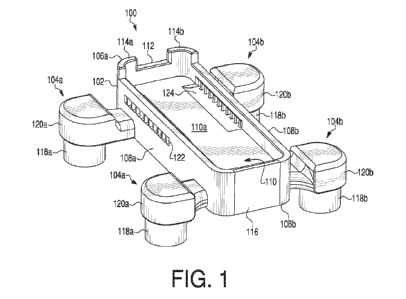
[028] FIG. 1 shows a perspective view of a support holder 100 for a test
device.
Support holder 100 may be designed to contain any known test device, such as a
DNA/RNA
sequencer. Support holder 100 may include a base 102 and projections 104a,
104b. Support
8
CA 03166779 2022- 8-2
WO 2021/158979
PCT/US2021/016902
holder 100 may be formed of any suitable material with sufficient weight to
aid in the
stability of the test device, and/or with any characteristics suitable for use
in a laboratory
setting. For example, support holder 100 may be made from a nylon carbon fiber
material
and/or other chemically resistant materials. Projections 104 may be made from,
or may
include, any natural or synthetic nonslip material, for example, rubber
materials, e.g.,
neoprene, and/or plastic materials, e.g., polyvinyl chloride.
[029] Base 102 may include a first plurality of sidewalls 106a, 106b and a
second
plurality of sidewalls 108a, 108b. First plurality of sidewalls 106a, 106b and
second plurality
of sidewalls 108a, 108b may define a cavity 110 in base 102. Cavity 110 may be
configured
to include a surface 110a for receiving a portion of a test device. Cavity 110
may be of any
suitable size and/or shape so as to contain a portion of a test device. A test
device should
accurately fit in cavity 110 such that the test device is stable and secured.
For example,
cavity 110 and test device may have a fit such that there is limited space or
no space between
the exterior of the test device and sidewalls 106a, 106b, 108a, 108b. For
example, cavity 110
and test device may have a transition fixed fit, wherein there may be a
negligible clearance
between the exterior of the test device and sidewalls 106a, 106b, 108a, 108b,
or a small
interference fit whereby the test device and base 102 can be assembled or
disassembled with
light pressing force. In FIG. 1, cavity 110 has a substantially rectangular
shape. In other
embodiments, however, cavity 110 may be substantially square, oval, or any
other suitable
shape, so long as cavity 110 defines a space large enough to contain a portion
of the test
device. Further, base 102 may have rounded or sharp corners and/or edges.
Surface 110a
may be substantially flat to allow a test device to be placed evenly on
surface 110a. In other
embodiments, surface 110a may be any suitable shape so long as a test device
could properly
fit on surface 110a and in cavity 110.
9
CA 03166779 2022- 8-2
WO 2021/158979
PCT/US2021/016902
[030] In some embodiments, first plurality of sidewalls 106a, 106b may have a
first
length 602 (shown in FIG. 6), wherein first length 602 may range from about 20
mm to about
50 mm. For example, first length 602 may range from about 25 mm to about 45
mm, or from
about 30 mm to about 40 mm. For example, first length 602 may be about 50 mm,
about 45
mm, about 40 mm, about 35 mm, or about 30 mm. In at least one example, first
length 602
may be between about 40 mm and about 41 111111, such as 40.15 mm. In some
embodiments,
second plurality of sidewalls 108a, 108b have a second length 604 (shown in
FIG. 6),
wherein second length 604 may range from about 90 mm to about 130 mm. For
example,
second length 604 may range from about 95 mm to about 125 mm, or from about
100 mm to
about 120 mm. For example, second length 604 may be about 130 mm, about 125
mm, about
120 mm, about 115 mm, about 110 mm, about 105 mm, or about 100 mm. In at least
one
example, second length 604 may be between about 112 mm and about 113 mm, such
as
112.45 mm. In some embodiments of the present disclosure, second length 604
may be
greater than first length 602.
[031] In some embodiments, sidewalls 106a, 106b, 108a, and 108b, may have a
thickness 606 (shown in FIG. 6) ranging from about 6.0 mm to about 8.0 mm. For
example,
thickness 606 may range from about 6.2 mm to about 7.5 mm or from about 6.4 mm
to about
7.0 mm. In at least one example, thickness 606 may be between about 6.4 mm and
about 6.5
mm, such as 6.49 mm. In some embodiments, sidewalls 106a, 106b, 108a, and
108b, may
have a height 402 (shown in FIG. 4) ranging from about 20 mm to about 30 mm.
For
example, height 402 may range from about 22 mm to about 28 mm or from about 24
mm to
about 26 mm. For example, height 402 may be about 20 mm, about 21 mm, about 22
mm,
about 23 mm, about 24 mm, about 25 mm, about 26 mm, about 27 mm, about 28 mm,
about
29 mm, or about 30 mm. In at least one example, height 402 may be 25 mm. While
various
exemplary dimensions for support holder 100 are described herein, it is to be
understood that
CA 03166779 2022- 8-2
WO 2021/158979
PCT/US2021/016902
support holder 100 may have any suitable dimension for holding and supporting
a test device,
and/or for meeting other goal(s) of the present disclosure.
[032] Support holder 100 may include a plurality of projections 104a, 104b,
which
may extend away from base 102, which may increase an overall width of support
holder 100.
The use of projections 104a, 104b and the wide footing of support holder 100
may increase
the stability of support holder 100. For example, when a test device is placed
atop cavity
110, the weight of the test device may be more evenly distributed across an
entirety of
support holder 100 because of the wider footing of support holder 100 due to
the projections.
Projections 104a, 104b may also elevate base 102 and the test device above a
surface, e.g., a
laboratory bench. As discussed above, the cool temperature of the laboratory
bench may
impact the temperature of the test device. By elevating the test device and
creating a gap
between the test device and the laboratory bench, the test device may heat up
faster and be
able to maintain the desired temperature. This may increase efficiency
throughout the testing
duration, as temperature fluctuations may negatively impact the samples and
testing results.
[033] The number of projections may vary, so long as support holder 100 is
steady
and any weight placed on support holder 100 is evenly distributed. As shown in
FIG. 1, base
102 may include a first pair of projections 104a and a second pair of
projections 104b,
wherein first pair of projections 104a may extend from one sidewall of second
plurality of
sidewalls 108a and second pair of projections 104b may extend from another
sidewall of
second plurality of sidewalls 108b.
[034] Referring to FIG. 1, each projection 104a, 104b may include a housing
120a,
120b to include a leg portion 118a, 118b. As shown in the figures, each
housing may be
configured to receive its con-esponding leg portion. Leg portions 118a, 118b
may extend in a
downwards direction and may provide support and stability for support holder
100. When
support holder 100 is placed on a surface, leg portions 118a, 118b may be in
direct contact
11
CA 03166779 2022- 8-2
WO 2021/158979
PCT/US2021/016902
with a surface of a table or bench. Leg portion(s) 118a, 118b, may also
prevent heat loss, as
contact between the test device and laboratory surface may impact the
temperature of the test
device, as discussed above. Leg portions 118a, 118b may include any natural or
synthetic
nonslip material, for example, rubber materials, e.g., neoprene, and/or or
plastic materials,
e.g., polyvinyl chloride. The materials and position of leg portion(s) 118a,
118b may prevent
support holder 100 from sliding around and/or off of a surface, and as such
may protect the
test device from vibrations and/or movements. The materials of leg portion(s)
118a, 118b,
may also help maintain the temperature of the test device. Leg portion(s)
118a, 118b may be
any appropriate shape to be received in housing 120a, 120b and to provide
steadiness and
stability to support holder 100.
[035] Referring to FIG. 2, each projection 104a, 104b may include a neck
portion
210 and a leg portion 212. Neck portion(s) 210 may be disposed between leg
portion(s) 212
and base 102. For example, and as shown in the figures, neck portion(s) 210
may be
configured to connect leg portion(s) 212 to base 102. Neck portion(s) 210 may
have a flat
surface and may extend from base to leg portion(s) 212. Neck portion(s) 210
may have a first
height 210a and leg portion(s) 212 may have a second height 212a. In some
embodiments of
the present disclosure, second height 212a may be greater than first height
210a. In
alternative embodiments of the present disclosure, first height 210a may be
equal to second
height 212a. First height 210a may range from about 1 mm to about 5 mm. For
example,
first height 210a may be about 1 mm, about 2 mm, about 3 mm, about 4 mm, or
about 5 mm.
In at least one example, first height 210a may be 3 mm. Second height 212a may
range from
about 1 mm to about 10 mm. For example, second height 212a may be about 1 mm,
about 2
mm, about 3 mm, about 4 mm, about 5 mm, about 6 mm, about 7 mm, about 8 mm,
about 9
mm, or about 10 mm. A length 210b between an outermost edge of neck portion(s)
210,
from a point of view facing one of first plurality of sidewalls 106a, 106b
(sidewall 106b is
12
CA 03166779 2022- 8-2
WO 2021/158979
PCT/US2021/016902
shown in FIG. 2) may range from about 50 mm to about 70 mm. For example,
length 210b
may range from about 55 mm to about 65 mm or from about 58 mm to about 62 mm.
For
example, length 210b may be about 55 mm, about 56 mm, about 57 mm, about 58
mm, about
59 mm, about 60 mm, about 61 mm, about 62 mm, about 63 mm, about 64 mm, or
about 65
mm. In at least one example, length 210b may be between about 59 mm and about
60 mm,
such as 59.10 mni.
[036] Referring to FIG. 3, first sidewall 106a of first plurality of sidewalls
106a,
106b may include a center notch 112 positioned between first corner portion
114a and second
corner portion 114b. Center notch 112 may serve as an opening to allow a test
device atop,
within, or partially within base 102 to connect to an external device, e.g., a
computer. For
example, a test device may require a cable for connecting to a computer or
laptop. When a
test device is placed into cavity 110 of base 102, center notch 112 may be
configured so that
a cable may pass through center notch 112 and contact the test device. Center
notch 112 may
allow a cable to pass through it and contact the test device such that the
test device may fit
snugly/appropriately into cavity 110.
[037] As shown in FIG. 3, center notch 112 may have any suitable shape to
allow
for proper connection of a test device to a cable or cord, e.g., a data or
power cord, such as a
USB cord. Center notch 112 may also serve as a reinforcement for the USB cord,
and/or for
a connection between the USB cord and a test device. A test device may be
placed atop
surface 110a of base 102, such that a USB cord may be placed through notch
112. As
discussed above, the USB cord may serve as a connection between the test
device and an
external computing device, e.g., a laptop. Center notch 112 may prevent
loosening of the
USB cord connection during loading of the samples and throughout the testing
duration.
[038] In some embodiments, center notch 112 may have a length 302 ranging from
about 15 mm to about 20 mm. For example, center notch 112 may have length 302
of about
13
CA 03166779 2022- 8-2
WO 2021/158979
PCT/US2021/016902
15 mm, about 16 mm, about 17 mm, about 18 mm, about 19 mm, or about 20 mm. In
at least
one example, center notch 112 may have a length 302 of between about 16 mm and
about 17
mm, such as 16.10 mm. Center notch 112 may be positioned in between first
corner portion
114a and second corner portion 114b. In some embodiments, center notch 112 may
be
centered between first corner portion 114a and second corner portion 114b; in
other
embodiments, center notch 112 may he offset from a central position. In
further
embodiments, center notch 112 may be replaced with an opening passing through
a sidewall,
such as first sidewall 106a of the plurality of sidewalls.
[039] First corner portion 114a and second corner portion 114b may extend in a
direction away from base 102, such as upwards from base 102. As shown in FIGS.
4 and 5,
first corner portion 114a and second corner portion 114b may each have a
height 404 greater
than a height 402 of second plurality of sidewalls 108a, 108b. In some
embodiments, corner
portions 114a, 114b may have a height up to 10 mm greater than a height of
second plurality
of sidewalls 108a, 108b. For example, corner portions 114a, 114b may have a
height about 1
mm, about 2 mm, about 3 mm, about 4 mm, about 5 mm, about 6 mm, about 7 mm,
about 8
mm, about 9 mm, or about 10 mm, greater than a height of second plurality of
sidewalls
108a, 108b. Corner portions 114a, 114b may have any suitable shape to properly
fit a test
device. In at least one embodiment, and as shown in FIG. 1, corner portions
114a, 114b may
have a curved shape.
[040] Referring again to FIG. 1, second sidewall 106b of the first plurality
of
sidewalls may include a removable portion 116. Removable portion 116 may be
configured
to cover an opening 202 (FIG. 2) into an interior 702 (FIG. 7) of base 102.
For example,
removable portion 116 may be completely removable from base 102. In other
words, when a
user wants to expose opening 202, removable portion 116 may be removed from
base 102 (as
shown in FIG. 2). Alternatively, removable portion 116 may slide to expose
opening 202,
14
CA 03166779 2022- 8-2
WO 2021/158979
PCT/US2021/016902
e.g., removable portion 116 may slide in an upwards direction or downwards
direction, such
that removable portion 116 may remain attached to base 102, while opening 202
is exposed.
In another example, removable portion 116 may simply fold open to expose
opening 202,
e.g., removable portion 116 may have a hinge that would allow it to fold open.
[041] Referring to FIG. 2, opening 202 may be between corner portions 204a,
204b.
Opening 202 may allow for the placement of a weighted insert (not shown).
Opening 202
may be any suitable shape configured to allow for insertion of the weighted
insert into
interior 702 (depicted in FIG. 7) of base 102. Opening 202 may have a
substantially circular
shape or a substantially rectangular shape, or any other suitable shape. FIG.
2 shows an
exemplary opening 202 in a substantially circular shape. Opening 202 may
extend at least
partially through interior 702 of base 102 (as shown in FIG. 7). In at least
one example,
opening 202 may extend from first sidewall 106a to second sidewall 106b. In
embodiments
where opening 202 may extend from first sidewall 106a to second sidewall 106b,
interior 702
may be empty (i.e., hollow). A weighted insert, as described below, may be
inserted into
interior 702. Alternatively, a weighted insert may be pre-positioned into the
interior of the
base, or formed as a part of the base.
[042] As described above, the weighted insert (not shown in the figures) may
counteract the light weight of a test device. The weighted insert may have any
suitable
weight such that the weighted insert may be properly placed through opening
202 and into
interior 702. The weighted insert may have a weight greater than or equal to
about 0.10
pounds. For example, the weight of the weighted insert may be greater than or
equal to about
0.12 pounds, about 0.15 pounds, or about 0.20 pounds. In at least one example,
the weight of
the weighted insert may be between about 0.20 and about 0.30 pounds, such as
between about
0.20 and about 0.25 pounds. The weighted insert may have any shape suitably
configured to
fit into opening 202 and interior 702. In some embodiments, for example, the
weighted insert
CA 03166779 2022- 8-2
WO 2021/158979
PCT/US2021/016902
may have a substantially square shape or a substantially rectangular shape. In
at least one
example, the weighted insert may have a rod-like shape. The weighted insert
may be formed
of any suitable material with appropriate density and resistance to corrosion.
Suitable
materials may have a high density. Additionally, suitable materials may be
resistant to
corrosion, toxicity, and contamination. For example, the weighted insert may
be formed of
stainless steel, sand, water, lead, platinum, clay, molybdenum, mercury,
iridium, osmium,
uranium, tungsten, titanium, nickel, carbon, similar metals, non-metals, or
combinations
thereof. In at least one example, the weighted insert may be formed of
tungsten carbide.
[043] In some embodiments, at least one sidewall 106a, 106b, 108a, 108b may
include at least one air vent 122 (shown in sidewalls 108a, 108b in FIGS. 1,
4, and 5). Air
vents 122 may be any suitable shape and may be present in any suitable number.
As shown
in FIG. 1, surface 110a may include at least one cavity 124 in fluid
communication with at
least one air vent or plurality of air vents 122. FIG. 6 shows a top view of
cavities 608a,
608b. The air vent(s) 122 and corresponding cavities 608a, 608b may allow for
cooling of
the test device while in use, which may allow the test device to run for long
testing durations
and may help prevent overheating and/or damage to the test device.
[044] The description above and examples are illustrative, and are not
intended to be
restrictive. One of ordinary skill in the art may make numerous modifications
and/or changes
without departing from the general scope of the invention. For example, and as
has been
referenced, aspects of above-described embodiments may be used in any suitable
combination with each other. Additionally, portions of the above-described
embodiments
may be removed without departing from the scope of the invention. In addition,
modifications may be made to adapt a particular situation or aspect to the
teachings of the
various embodiments without departing from their scope. Many other embodiments
will also
be apparent to those of skill in the art upon reviewing the above description.
16
CA 03166779 2022- 8-2