Note: Descriptions are shown in the official language in which they were submitted.
ALL-TERRAIN VEHICLE
FIELD OF THE DISCLOSURE
[0001] The present invention relates to an all-terrain vehicle and, more
particularly, to
an all-terrain utility vehicle configured to operate in mud and water
conditions.
BACKGROUND AND SUMMARY OF THE DISCLOSURE
[0002] Generally, all-terrain vehicles ("ATVs") and utility vehicles
("UVs") are used
to carry at least one person over a variety of terrains. For example, the ATVs
and UVs are
configured to traverse dry dirt trails, paved roads, and wet trails with deep
water and/or mud
conditions.
[0003] However, when the ATVs and UVs are traversing deep mud and/or water
conditions, the air intake and/or cooling assembly of the powei _____ (lain
assembly may be clogged
with mud and/or submerged in water. As such, portions of the powertrain
assembly may
become damaged and/or the ATVs and UVs may be prevented from operating due to
the lack
of air provided to the powei Li ain assembly for combustion and/or cooling.
Therefore, a need
exists for an ATV or UV configured to operate in deep mud and water
conditions.
SUMMARY OF THE DISCLOSURE
[0004] According to an illustrative embodiment of the present disclosure,
an all-
terrain vehicle ("ATV") includes a plurality of ground engaging members and a
frame
supported above a ground surface by the plurality of ground engaging members.
The frame
extends along a longitudinal centerline of the ATV. The ATV further includes
an operator
seat supported by the frame, an engine supported by the frame, and a
continuously variable
transmission ("CVT") supported by the frame and operably coupled to the
engine.
Additionally, the ATV includes a CVT cooling air inlet fluidly coupled to the
CVT and
positioned forward of a forward end of the operator seat, and a CVT cooling
air outlet fluidly
coupled to the CVT and positioned forward of the forward end of the operator
seat.
[0005] According to another illustrative embodiment of the present
disclosure, an all-
terrain vehicle ("ATV") comprises a plurality of ground engaging members and a
frame
supported by the plurality of ground engaging members. The frame extends along
a
longitudinal centerline of the ATV. The ATV further includes an operator seat
supported by
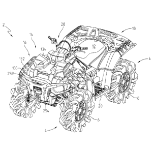
the frame, first and second footwells positioned below the operator seat, an
engine supported
by the frame, and a continuously variable transmission ("CVT") supported by
the frame and
-1-
Date Recue/Date Received 2022-07-05
operably coupled to the engine. The ATV also includes a CVT cooling air inlet
fluidly
coupled to the CVT and positioned forward of the operator seat and along the
centerline, and
a CVT cooling air outlet fluidly coupled to the CVT and positioned forward of
the operator
seat and laterally inward of the footwells. Additionally, the ATV includes an
engine air inlet
fluidly coupled to the engine and positioned forward of the operator seat and
laterally inward
of the footwells.
[0006] According to a further illustrative embodiment of the present
disclosure, an
all-terrain vehicle ("ATV") comprises a plurality of ground engaging members
and a frame
supported above a ground surface by the plurality of ground engaging members.
The frame
extends along a longitudinal centerline of the ATV. Additionally, the ATV
includes an
operator seat supported by the frame, an engine supported by the frame, and a
continuously
variable transmission ("CVT") supported by the frame and operably coupled to
the engine.
The ATV further includes a cooling assembly including a radiator and a
plurality of fans
fluidly coupled to the radiator. A forward end of the radiator is positioned
rearward of a
forward end of the ATV. Additionally, the plurality of fans are angled
laterally away from
the longitudinal centerline.
[0007] According to yet another illustrative embodiment of the present
disclosure, an
all-terrain vehicle ("ATV") comprises a plurality of ground engaging members
and a frame
supported above a ground surface by the plurality of ground engaging members.
The frame
extends along a longitudinal centerline of the ATV. Additionally, the ATV
comprises an
operator seat supported by the frame, an engine supported by the frame, and a
continuously
variable transmission ("CVT") supported by the frame and operably coupled to
the engine.
The ATV also includes a cooling assembly including a radiator and at least one
fan
positioned above the radiator. A forward end of the radiator is positioned
rearward of a
forward end of the ATV.
[0008] According to still yet another illustrative embodiment of the
present
disclosure, an all-terrain vehicle ("ATV") comprises: a plurality of ground
engaging
members; a frame supported above a ground surface by the plurality of ground
engaging
members and extending along a longitudinal centerline of the ATV; an operator
seat
supported by the frame; an engine supported by the frame; a continuously
variable
transmission ("CVT") supported by the frame and operably coupled to the
engine; and a
cooling assembly including a radiator and a plurality of fans fluidly coupled
to the radiator, a
forward end of the radiator being positioned rearward of a forward end of the
ATV, and the
plurality of fans being angled laterally away from the longitudinal
centerline.
-2-
Date Recue/Date Received 2022-07-05
[0008a] According to still yet another illustrative embodiment of the
present
disclosure, an all-terrain vehicle ("ATV") comprises: a plurality of ground
engaging
members; a frame supported above a ground surface by the plurality of ground
engaging
members and extending along a longitudinal centerline of the ATV; an operator
seat
supported by the frame; an engine supported by the frame; a continuously
variable
transmission ("CVT") supported by the frame and operably coupled to the
engine; and a
cooling assembly including a radiator and at least one fan positioned above
the radiator, a
forward end of the radiator being positioned rearward of a forward end of the
ATV, and the at
least one fan being configured to draw air through the radiator from below the
ATV.
BRIEF DESCRIPTION OF THE DRAWINGS
[0009] The above mentioned and other features of this invention, and the
manner of
attaining them, will become more apparent and the invention itself will be
better understood
by reference to the following description of embodiments of the invention
taken in
conjunction with the accompanying drawings, where:
[0010] Fig. 1 is a left front perspective view of an all-terrain vehicle of
the present
disclosure;
[0011] Fig. 2 is a right rear perspective view of the vehicle of Fig. 1;
[0012] Fig. 3 is a left bottom perspective view of the vehicle of Fig. 1;
[0013] Fig. 4 is a left side view of the vehicle of Fig. 1;
[0014] Fig. 5 is a right side view of the vehicle of Fig. 1;
[0015] Fig. 6 is atop view of the vehicle of Fig. 1;
[0016] Fig. 7 is a front view of the vehicle of Fig. 1;
[0017] Fig. 8 is a rear view of the vehicle of Fig. 1;
[0018] Fig. 9 is a left front perspective view of a frame assembly of the
vehicle of
Fig. 1;
[0019] Fig. 10 is a right rear perspective view of the frame assembly of
Fig 9;
[0020] Fig. 11 is a left front perspective view of a front suspension
assembly of the
vehicle of Fig. 1;
[0021] Fig. 12 is a left front perspective view of an upper control arm and
a lower
control arm of the front suspension assembly of Fig. 11;
[0022] Fig. 13 is a right rear perspective view of a rear suspension
assembly of the
vehicle of Fig. 1;
-3-
Date Recue/Date Received 2022-07-05
[0023] Fig. 14 is a right rear perspective view of an upper control arm and
a lower
control arm of the rear suspension assembly of Fig. 13;
[0024] Fig. 15 is a left front perspective view of a battery of the vehicle
of Fig. 1
supported by the frame assembly of Fig. 9;
[0025] Fig. 16 is an exploded view of the battery, a retaining member, and
a portion
of the frame assembly of Fig. 15;
[0026] Fig. 17 is a side view of the battery of Fig. 15 and a cooling
assembly of the
vehicle of Fig. 1;
[0027] Fig. 18 is a top view of a hood assembly of the vehicle of Fig. 1;
[0028] Fig. 19A is a left front perspective view of a lower hood member of
the hood
assembly of Fig. 18, including a support member for a plurality of fans of the
cooling
assembly;
[0029] Fig. 19B is a left front perspective view of the lower hood member
supporting
the plurality of fans of the cooling assembly and a plurality of snorkels
positioned rearward
of the plurality of fans;
[0030] Fig. 19C is a front view of a portion of the support member of the
lower hood
assembly of Fig. 19A;
[0031] Fig. 19D is a side view of the portion of the support member of the
lower hood
assembly of Fig. 19C;
[0032] Fig. 20 is an exploded view of the hood assembly of Fig. 18 and the
cooling
assembly;
[0033] Fig. 21A is a rear view of the plurality of snorkels of Fig. 19B and
an upper
hood portion of the hood assembly of Fig. 18;
[0034] Fig. 21B is an exploded view of the snorkels and the upper hood
portion of
Fig. 21A;
[0035] Fig. 22 is a cross-sectional view of the snorkels of Fig. 21B, taken
along line
22-22 of Fig. 18;
[0036] Fig. 23 is a cross-sectional view of air flow through one of the
snorkels of Fig.
21B;
[0037] Fig. 24 is a left front perspective view of the snorkels of Fig. 21B
each fluidly
coupled to a fluid conduit;
[0038] Fig. 25 is a top view of the snorkels and fluid conduits of Fig. 24
and an
airbox and a continuously variable transmission of a powei it am n assembly
of the vehicle of
Fig. 1;
-4-
Date Recue/Date Received 2022-07-05
[0039] Fig. 26 is a right rear perspective view of the airbox assembly of
Fig. 24;
[0040] Fig. 27 is an exploded view of the airbox assembly of Fig. 26;
[0041] Fig. 28 is a cross-sectional view of a portion of the airbox
assembly of Fig. 26,
taken along line 28-28 of Fig. 26;
[0042] Fig. 29 is a cross-sectional view of a portion of the airbox
assembly of Fig. 26,
taken along line 29-29 of Fig. 26;
[0043] Fig. 30 is a left rear perspective view of a footwell of the vehicle
of Fig. 1;
[0044] Fig. 31 is a right rear perspective view of an underside of the
footwell of Fig.
30;
[0045] Fig. 32 is an exploded view of the footwell of Fig. 30;
[0046] Fig. 33 is a top view of the footwell of Fig. 30;
[0047] Fig. 34 is a left front perspective view of a front end of the
vehicle of Fig. 1,
including a front bumper and winch assembly;
[0048] Fig. 35 is an exploded view of the winch assembly and front bumper
of Fig.
34;
[0049] Fig. 36 is a right rear perspective view of handlebar assembly of
the vehicle of
Fig. 1; and
[0050] Fig. 37 is an exploded view of the handlebar assembly of Fig. 36.
[0051] Corresponding reference characters indicate corresponding parts
throughout
the several views. The drawings represent embodiments of the present invention
and the
features of the drawings are shown to scale.
DETAILED DESCRIPTION OF THE DRAWINGS
[0052] The embodiments disclosed below are not intended to be exhaustive or
to limit
the invention to the precise forms disclosed in the following detailed
description. Rather, the
embodiments are chosen and described so that others skilled in the art may
utilize their
teachings. While the present disclosure is primarily directed to a utility
vehicle, it should be
understood that the features disclosed herein may have application to other
types of vehicles
such as other all-terrain vehicles, motorcycles, snowmobiles, and golf carts.
[0053] Referring to Figs. 1-8, an illustrative embodiment of an all-terrain
vehicle
("ATV") 2 is shown. Illustratively vehicle 2 may be configured for deep mud
and water
conditions, as disclosed further herein. Vehicle 2 includes a plurality of
ground-engaging
members 4, illustratively front wheels 6 and rear wheels 8. Front and rear
wheels 6, 8 may
include approximately 28-34 inch tires and approximately 12-14 inch metal
wheels. In one
-5-
Date Recue/Date Received 2022-07-05
embodiment, one or more of ground-engaging members 4 may be replaced with
tracks, such
as the Prospector II Tracks available from Polaris Industries Inc. of Medina,
Minnesota or
non-pneumatic tires, such as those shown in U.S. Patent Nos. 8,176,957
(Attorney Docket
PLR-09-25371.01P) and 8,104,524 (Attorney Docket PLR-09-25369.01P). Vehicle 2
is
configured for off-road conditions, including deep mud and/or water
conditions.
Additionally, vehicle 2 is configured to operate on trails and has a width of
approximately 45-
50 inches and a wheel base length extending from the axis of rotation of front
wheels 6 to the
axis of rotation of rear wheels 8 of approximately 50-65 inches.
[0054] Vehicle 2 further includes a frame assembly 10 (Figs. 9 and 10)
supported
above a ground surface G (Fig. 4) by ground-engaging members 4. Frame assembly
10
extends along a longitudinal centerline CL of vehicle 2 (Fig. 6). Frame
assembly 10 supports
a seat 12, illustratively a straddle seat, and a plurality of body panels 14,
which includes a
hood assembly 16, a cargo area 18, and a plurality of footwells 20. Seat 12
may be
configured to support the operator of vehicle 2 and a passenger seated
rearward of the
operator. Additionally, frame assembly 10 supports a powernain assembly (Fig.
24) of
vehicle 2, including at least an engine 24, a continuously variable
transmission ("CVT") 26, a
front differential (not shown), and a rear differential (not shown). Powei
Li ain assembly 22
may operate at a horsepower of up to 90 hp and engine 24 may have a capacity
of 500-1000
cc. A steering assembly 28 cooperates with powei h ain assembly 22 to
operate vehicle 2.
[0055] Referring to Figs. 9 and 10, frame assembly 10 includes upper
longitudinally-
extending frame members 30 and lower longitudinally-extending frame members
32. Upper
longitudinally-extending members 30 support at least seat 12 and cargo area
18. Upper and
lower longitudinally-extending frame members 30, 32 are generally coupled
together through
front upstanding members 34 and rear upstanding members 36. Frame assembly 10
further
includes a support pan or plate 38 and a brace 39 for supporting engine 24
(Fig. 24) and/or
other components of powei ________________________________________ it am n
assembly 22. A plurality of braces 40 are extend laterally
outwardly from lower longitudinally-extending frame members 32 to support
footwells 20
(Fig. 1), as detailed further herein.
[0056] Referring still to Figs. 9 and 10, frame assembly 10 further
includes a steering
mount 42 for supporting a portion of steering assembly 28, such as a steering
column 44.
Additionally, steering mount 42 also may support a dash or body member 46 for
a gauge 48
(Fig. 36). Gauge 48 may be any electrical or mechanical gauge configured to
provide
information (e.g., speed, fuel level, terrain, GPS, etc.) to the operator. In
one embodiment,
body member 46 may include a key switch and other electrical components of
vehicle 2.
-6-
Date Recue/Date Received 2022-07-05
[0057] Referring now to Figs. 9-14, vehicle 2 includes a front suspension
assembly 50
and a rear suspension assembly 76 supported by frame assembly 10. As shown in
Figs. 9, 11,
and 12, front suspension assembly 50 includes an upper control arm 52, a lower
control arm
54, and a linear force actuator, such as a shock absorber 56. An inner end of
upper control
arm 52 includes mounting members 53 which are pivotably coupled to a brace 58
of frame
assembly 10 and an outer end of upper control arm 52 includes a mounting
member 55 which
is pivotably coupled to a front hub assembly 60 of vehicle 2. Front hub
assembly 60 includes
a hub portion 62 and a brake disc 64 to form a portion of front wheels 6.
Upper control arm
52 includes a forward member 52a and a rearward member 52b. Forward member 52a
extends in a straight or linear configuration between mounting members 53, 55.
Rearward
member 52b includes a rearward bend such that a distance between the outer
ends of
members 52a, 52b is less than a distance between the inner ends of members
52a, 52b.
[0058] Lower control arms 54 are positioned vertically below upper control
arms 52.
An inner end of lower control arm 54 includes mounting members 66 which are
pivotably
coupled to a brace 68 of frame assembly 10 and an outer end of lower control
arm 54
includes a mounting member 70 which is pivotably coupled to front hub assembly
60. Lower
control arm 54 includes a forward member 54a and a rearward member 54b.
Members 54a,
54b each extend in a continuous curvature between mounting members 66, 70. In
other
words, members 54a, 54b have an arcuate profile with a constant radius
extending
continuously between mounting members 66, 70. As such, the ground clearance of
vehicle 2
is increased by the curved configuration of members 54a, 54b. For example, the
ground
clearance of vehicle 2 may be approximately 14 inches.
[0059] Shock absorbers 56 of front suspension assembly 50 include a lower
end
pivotably coupled to a bracket 72 of upper control arms 52. Additionally, an
upper end of
shock absorbers 56 is pivotably coupled to a bracket 74 of frame assembly 10.
As shown in
Fig. 9, bracket 74 is coupled to front upstanding members 34 and upper
longitudinally-
extending members 30.
[0060] Referring to Figs. 10, 13 and 14, rear suspension assembly 76
includes an
upper control arm 78, a lower control arm 80, and a linear force actuator,
such as a shock
absorber 82. An inner end of upper control arm 78 includes mounting members 84
which are
pivotably coupled to a bracket 86 supported on a brace 88 of frame assembly
10. An outer
end of upper control arm 78 includes a mounting member 90 which is pivotably
coupled to a
bracket 92 on a rear hub assembly 94 of vehicle 2. Rear hub assembly 94
includes a hub
-7-
Date Recue/Date Received 2022-07-05
portion 96 and a brake disc 98 to form a portion of rear wheels 8. Upper
control arm 78
extends in a straight or linear configuration between mounting members 84, 90.
[0061] Lower control arms 80 are positioned vertically below upper control
arms 78.
An inner end of lower control arm 80 includes mounting members 100 which are
pivotably
coupled to a bracket 102 of frame assembly 10 and an outer end of lower
control arm 80
includes a mounting member 104 which is pivotably coupled to a portion of rear
hub
assembly 94. Lower control arm 80 includes a forward member 80a and a rearward
member
80b. Members 80a, 80b extend in a continuous curvature between mounting
members 100,
104. In other words, members 80a, 80b have an arcuate profile with a constant
radius
extending continuously between mounting members 100, 104. As such, the ground
clearance
of vehicle 2 is increased by the curved configuration of members 80a, 80b. For
example, the
ground clearance of vehicle 2 may be approximately 14 inches.
[0062] Shock absorbers 82 of rear suspension assembly 76 include a lower
end
pivotably coupled to a bracket 106 supported on a cross member 108 extending
between
members 80a, 80b of lower control arms 80. Additionally, an upper end of shock
absorbers
82 are pivotably coupled a bracket 110 of frame assembly 10. As shown in Fig.
9, bracket
110 is coupled to rear upstanding members 36 and upper longitudinally-
extending members
30.
[0063] Referring to Figs. 15-17, a battery assembly of vehicle 2 includes
at least one
battery 112. A retaining member 114 and a plate 116 couple battery 112 to
frame assembly
with fasteners 118. More particularly, plate 116 is coupled to front
upstanding members
34 of frame assembly 10 and extends in a longitudinally forward direction from
front
upstanding members 34. Illustrative plate 116 includes tabs 122 which are
coupled to front
upstanding members 34 with fasteners 120 (Fig. 17). Plate 116 has a horizontal
surface on
which battery 112 is positioned such that battery 112 is adjacent and forward
of front
upstanding members 34.
[0064] Battery 112 is retained on plate 116 with retaining member 114,
which may be
a strap, cable, or any other known retaining member configured to retain
battery 112 on
frame assembly 10. Illustratively, retaining member 114 has a rear portion
114a in contact
with a rear face of battery 112, an upper portion 114b in contact with a top
face of battery
112, and a front portion 114c in contact with a front face of battery 112. As
such, retaining
member 114 extends around a portion of battery 112 to retain battery 112
through a friction
or interference fit. Retaining member 114 is coupled to a front portion of
plate 116 with
fastener 118 and is coupled to a rear portion of plate 116 with a catch member
124 formed on
-8-
Date Recue/Date Received 2022-07-05
rear portion 114a of retaining member 114. More particularly, catch member 124
may have a
hook, tab, or other profile configured to be received within an opening 126 of
the rear portion
of plate 116. In this way, battery 112 is removable from vehicle 2 by
releasing fastener 118
and catch member 124 from plate 116 and removing retaining member 114.
[0065] Referring to Fig. 17, illustrative battery 112 is positioned at the
front of
vehicle 2 and vertically below a forward portion of a cooling assembly 130 of
vehicle 2. As
shown in Figs. 18-20, cooling assembly 130 includes at least one fan 138 and a
radiator 152
which are positioned below hood assembly 16, as disclosed further herein. In
one
embodiment, cooling assembly 130 includes dual fans 138 and a single radiator
152
positioned vertically below fans 138 which may increase air flow through
radiator 152.
[0066] Hood assembly 16 includes a lower hood member 132 and an upper hood
member 134. Lower hood member 132 and upper hood member 134 are generally
positioned
forward of a forward end 12a of operator seat 12 (Fig. 6) and upper hood
member 134 may
be positioned vertically above operator seat 12. Lower hood member 132 and
upper hood
member 134 may be comprised of a polymeric material and/or may be a composite
material.
In one embodiment, upper hood member 134 is removably coupled to lower hood
member
132 with a hinge 159. For example, hinge 159 may be a Lock & Ride component
available
from Polaris Industries Inc. of Medina, Minnesota. In this way, upper mood
member 134
may be removed to access cooling assembly 130, such as fans 138 and radiator
152 for
cleaning and/or service.
[0067] Referring to Figs. 19A-19D and 20, lower hood member 132 includes a
surface 140 with openings 136 each configured to receive one of fans 138 of
cooling
assembly 130. In one embodiment, each fan 138 may have a diameter of
approximately 5-10
inches, and illustratively, 7 inches. Fans 138 are coupled to surface 140 with
fasteners 142
which are received through apertures 144 (Figs. 19A, 19B). Surface 140 and,
therefore, fans
138 are angled laterally away from longitudinal centerline CL and are angled
downwardly in a
forward direction, as shown in Figs. 19C and 19D. More particularly, a
rotation axis R of fan
138 is angled relative to a vertical axis V which intersects rotation axis R.
For example,
rotation axis R is angled relative to vertical axis V by an angle a of
approximately 5-25 . In
one embodiment, angle a between rotation axis R and vertical axis V is
approximately 13 .
As such, surface 140 and fan 138 may be angled laterally away from
longitudinally centerline
CL by approximately 13 . Additionally, surface 140 and fan 138 are angled
downwardly in a
forward direction by an angle 13 defined between rotation axis R and vertical
axis V. In one
embodiment, angle 13 is approximately 5-25 and, illustratively, angle 13 may
be 16 . As such,
-9-
Date Recue/Date Received 2022-07-05
surface 140 and fan 138 are angled downwardly relative to a horizontal plane
intersecting
longitudinal centerline CL by approximately 16 . In this way, surface 140 and
fans 138 are
positioned at a compound angle relative to vertical axis V which intersects
rotation axis R of
fan 138.
[0068] As shown in Fig. 20, fans 138 are positioned directly above radiator
152.
Radiator 152 may be angled relative to a horizontal plane intersecting
longitudinal centerline
CL by an angle of 5-25 and, more particularly, 16 . In this way, mud, dirt,
water, snow, and
debris may slide off of radiator 152 rather than accumulate thereon if
radiator 152 was
positioned in a generally horizontal configuration. Additionally, a forward
end 152a (Fig. 17)
of radiator 152 is positioned rearward of a forwardmost surface 133 of lower
hood member
132 (Fig. 19B). As shown in Fig. 1, forwardmost surface 133 of lower hood
member 132 is
positioned rearward of a front bumper or fender 254. As such, forward end 152a
of radiator
152 is positioned rearward of front bumper 254. Radiator 152 is sealingly
coupled to a lower
surface of lower hood member 132 with a seal 156.
[0069] Radiator 152 is positioned below surface 140 and fans 138 are
configured to
draw air through radiator 152 from below vehicle 2 and from air flow through a
front grill
259 (Fig. 1). Additionally, because battery 112 is positioned at the front end
of vehicle 2 and
below only the forward portion of radiator 152, the majority of radiator 152
is exposed which
increases the unobstructed area of radiator 152 configured to receive air flow
from below
vehicle 2. More particularly, air from below radiator 152 and air flowing
through front grill
259 flows through radiator 152 due to the rotation of fans 138 and is
exhausted from fans 138
through a plurality of vents 158 in upper hood member 134.
[0070] Vents 158 are angled toward the side of vehicle 2 to prevent air
drawn through
fans 138 from being directed toward the operator. In one embodiment, one vent
158
generally faces laterally outward from longitudinal centerline CL toward a
right side of
vehicle 2 and the other vent 158 generally faces laterally outward from
longitudinal
centerline CL toward a left side of vehicle 2. In this way, air exhausted from
cooling
assembly 130 is directed away from the operator. Additionally, vents 158
direct hot air from
cooling assembly 130 away from heat-sensitive components of vehicle 2, such as
the fuel
tank. In operation, the temperature of the cooling fluid for engine 24 is
decreased when fans
138 rotate to draw air from below radiator 152 into radiator 152. The air
cools the cooling
fluid flowing through radiator 152 for cooling engine 24 and then the air
flows from radiator
152, through fans 138, and leaves vehicle 2 through vents 158. In one
embodiment, fans 138
operate continuously during operation of vehicle 2 to provide a constant air
flow through
-10-
Date Recue/Date Received 2022-07-05
radiator 152. Alternatively, cooling assembly 130 includes a thermostat (not
shown) for
operating fans 138 intermittently based on the temperature of the cooling
fluid within radiator
152. As such, when fans 138 are not operating, air flows through radiator 152
as ambient air
flows past radiator 152 during movement of vehicle 2.
[0071] Referring still to Fig. 20, lower hood member 132 also includes a
partition 146
positioned rearward of surface 140 and openings 136. Partition 146 is sealed
from upper
hood member 134 by a seal 154. Partition 146 cooperates with a rear wall 148
of lower hood
member 132 to define an opening 150 for receiving a plurality of snorkels or
air openings
160. In one embodiment, snorkels 160 are defined by rubber or other polymeric
boots and
are configured for air flow therethrough. Snorkels 160 are positioned within a
rearward
portion 176 of upper hood member 134 such that an upper wall 176a of rearward
portion 176
is positioned above snorkels 160 and a rear wall 176b of rearward portion 176
is positioned
rearward of snorkels 160. A front wall 176c of rearward portion 176 may
include a recess
179 for affixing a logo or other identifying information to hood assembly 16
of vehicle 2.
[0072] Snorkels 160 may be joined together through a coupling member 168.
Snorkels 160 extend vertically above lower hood member 132 and through opening
150.
Because upper hood member 134 is removably coupled to lower hood member 132
with
hinges 159, snorkels 160 may be easily accessed for cleaning, repair, etc.
[0073] In one embodiment, snorkels 160 are positioned at a vertical
distance greater
than that of seat 12 and are positioned forward of forward end 12a or seat 12.
Additionally,
snorkels 160 are positioned forward of a portion of steering assembly 28, such
as handlebars
282, and are laterally inward from footwells (Fig. 25). Additionally, snorkels
160 are
positioned rearward of fans 138 and a rear end 152b (Fig. 17) of radiator 152,
as shown in
Figs. 19B and 20. Illustratively, snorkels 160 are positioned above ground
surface G by
approximately 40-60 inches. For example, snorkels 160 may be approximately 48
inches
above ground G. In one embodiment, snorkels 160 are positioned at a greater
vertical
distance from ground G than the upper surface of front bumper 254 (Fig. 4).
Snorkels 160
may be supported on lower hood member 132 with conventional couplers (e.g.,
clamps, bolts,
rivets, welds, etc.).
[0074] Referring to Figs. 21A-23, snorkels 160 include a cooling air inlet
162 for
CVT 26 to provide cooling air to CVT 26, a cooling air outlet 164 for CVT 26
to expel hot
air from CVT 26 from vehicle 2, and a combustion air inlet 166 for engine 24
to provide
combustion air to engine 24. Cooling air inlet 162, cooling air outlet 164,
and combustion air
inlet 166 are generally positioned in a laterally-extending orientation. More
particularly, a
-11-
Date Recue/Date Received 2022-07-05
plane P extending from a right side RS to a left side LS of vehicle 2 which is
generally
perpendicular to longitudinal centerline CL intersects cooling air inlet 162,
cooling air outlet
164, and combustion air inlet 166, as shown in Fig. 25.
[0075] Cooling air inlet 162 is positioned along longitudinal centerline CL
and
includes an opening 170 which faces in a forward direction for receiving an
air flow Ai for
cooling CVT 26. As air flows into cooling air inlet 162, air flows in a
direction parallel to
longitudinal centerline CL. Cooling air outlet 164 is positioned laterally
adjacent cooling air
inlet 162 and longitudinal centerline CL and includes an opening 172 which is
angled relative
to cooling air inlet 162. In one embodiment, opening 172 generally faces a
left side of
vehicle 2 to receive an air flow Az from CVT 26 to prevent hot air exhausted
from CVT 26
from being directed toward the operator. Similarly, combustion air inlet 166
is positioned
laterally adjacent cooling air inlet 162 and longitudinal centerline CL and
includes an opening
174 which is angled relative to cooling air inlet 162. In one embodiment,
opening 174
generally faces a right side of vehicle 2 to draw in an air flow A3 into
engine 24 for
combustion therein. By positioning snorkels 160 in proximity to longitudinal
centerline CL,
air flow through snorkels 160 is not affected by vehicle 2 tilting during
operation thereof.
Additionally, the location of snorkels 160 is furthest from any conditions on
ground G, such
as mud, water, snow, dirt, and debris, thereby decreasing the likelihood that
snorkels 160 will
become clogged during operation of vehicle 2.
[0076] To decrease the likelihood of cooling air inlet 162, cooling air
outlet 164, and
combustion air inlet 166 scavenging air from each other during operation of
vehicle 2,
rearward portion 176 includes a plurality of baffles for separating openings
170, 172, 174
within rearward portion 176. More particularly, a first baffle 180 separates
opening 170 from
opening 172 such that the hot air flowing from cooling air outlet 164 is not
drawn into
cooling air inlet 162. Additionally, a second baffle 182 separates opening 170
from opening
174 such that cooling air inlet 162 does not scavenge air from combustion air
inlet 166 or
vice versa. Therefore, both engine 24 and CVT 26 receive sufficient quantities
of air for
combustion and cooling, respectively.
[0077] As shown in Figs. 23-25, snorkels 160 are coupled to a plurality of
conduits
184, 186, 188 for flowing air therethrough. Conduits 184, 186, 188 may be
comprised of a
polymeric material and may be formed through a blow molding process. As shown
in Fig.
25, conduits 184, 186, 188 are positioned generally inward of footwells 20 and
may extend in
both vertical and longitudinal directions.
-12-
Date Recue/Date Received 2022-07-05
[0078] More particularly, cooling air inlet 162 is coupled to a conduit 184
for
receiving air flow Ai through opening 170 and directing it toward CVT 26 to
cool CVT 26.
Conduit 184 may be a singular component or may be comprised of a plurality of
components,
such as a first conduit component 184a and a second conduit component 184b. As
shown in
Fig. 24, first conduit component 184a extends downwardly in a generally
vertical direction
and second conduit component 184b extends rearwardly in a generally
longitudinal direction.
An output end 184c of conduit 184 is fluidly coupled to an inlet of CVT 26. By
positioning
battery 112 at the front end of vehicle 2, conduit 184 is configured to extend
along a left side
of engine 24. As shown in Figs. 22 and 23, cooling air flow Ai flows into
opening 170 from
below vehicle 2 due to the rotation of fans 138 drawing air through radiator
152. In
particular, the cooling air flow Ai flows through a portion of lower hood
member 132,
through opening 150, and into upper hood member 134 before flowing into
opening 170,
through conduit 184, and into CVT 26.
[0079] Similarly, and referring to Figs. 24 and 25, cooling air outlet 164
is coupled to
a conduit 186 for flowing air flow A2 from CVT 26 toward opening 172 to expel
hot air from
CVT 26. Conduit 186 may be a singular component or may be comprised of a
plurality of
components, such as a first conduit component 186a, a second conduit component
186b, and
a third conduit component 186c. As shown in Fig. 24, first conduit component
186a extends
downwardly in a generally vertical direction, second conduit component 186b
extends
rearwardly in a generally longitudinal direction, and third conduit component
186c extends
laterally in a direction generally perpendicular to longitudinal centerline
CL. An intake end
186d of conduit 186 is fluidly coupled to an output port of CVT 26. By
positioning battery
112 at the front end of vehicle 2, conduit 186 is configured to extend along a
left side of
engine 24 and a rear side of CVT 26.
[0080] Additionally, and still referring to Figs. 24 and 25, combustion air
inlet 166 is
coupled to a conduit 188 for flowing air flow A3 from opening 174 and toward
engine 24 to
provide air to the combustion chamber (not shown) of engine 24 for combustion
therein.
Conduit 188 may be a singular component or may be comprised of a plurality of
components.
In one embodiment, conduit 188 extends downwardly from combustion air inlet
166 and
extends rearwardly toward engine 24.
[0081] As shown in Figs. 25, an output end 188a of conduit 188 is fluidly
coupled to
an airbox assembly 190 of engine 24. Airbox assembly 190 filters air flow A3
before the air
enters throttle bodies 212 of engine 24 for combustion therein. Throttle
bodies 212 are
supported on airbox assembly 190 with a support member 210 coupled to airbox
assembly
-13-
Date Recue/Date Received 2022-07-05
190. Throttle bodies 212 are configured to supply combustion air to engine 24
through
engine intakes 214.
[0082] Airbox assembly 190 includes a housing 192, a support plate 194
sealingly
coupled to a bottom surface of housing 192 with fasteners 196, a seal 195
positioned
intermediate support plate 194 and housing 192, a delete plate 198 coupled to
an upper
surface of housing 192 with fasteners 199, a panel or door 200 sealingly
coupled to a rear
surface of housing 192 with a seal 201, a breather tube 202 fluidly coupled to
the internal
volume of housing 192, and a filter 204 positioned within the internal volume
of housing 192
for filtering air flow A3 from conduit 188. Delete plate 198 may be coupled to
plate 200 with
a fastener 205. For example, as shown in Figs. 26 and 27, delete plate 198 may
include a
vertically-extending tab 206 which is coupled to an upper tab 208 of plate 200
with a coupler
207 and fastener 205. In one embodiment, plate 200 is comprised of 10-gauge
steel to
increase the torsional stability of airbox assembly 190 during operation of
vehicle 2. More
particularly, during operation of vehicle 2, airbox assembly 190 may
experience torsional or
other stresses as vehicle 2 moves along ground G and over objects and as
engine 24 operates;
however, plate 200 provides structural rigidity to housing 192 to decrease any
stresses
applied to airbox assembly 190.
[0083] Referring to Figs. 28 and 29, to flow air from combustion air inlet
166 into
engine 24, conduit 188 is coupled to a right side of housing 192 of airbox
assembly 190.
More particularly, output end 188a of conduit 188 includes a flange 216 which
abuts housing
192 and coupled thereto with fasteners 218, 219. Additionally, a tab 220 of
housing 192
extends laterally into output end 188a and sealingly engages output end 188a
through a seal
222 positioned around tab 220. As such, ambient air flows into combustion air
inlet 166,
through conduit 188, through output end 188a of conduit 188, and into housing
192 of airbox
assembly 190 through an opening 224 in the right side of housing 192. The
ambient air is
then filtered by filter 204 within housing 192 and flows into throttle bodies
212 before
flowing into a combustion chamber within engine 24.
[0084] Referring to Figs. 30-33, footwells 20 of vehicle 2 are shown.
Footwells 20
extend between a front upstanding body member 226 and a rear upstanding body
member
228 of body panels 14. Footwells 20 may be integrally formed with body members
226, 228
or may be coupled thereto through conventional coupling means (e.g.,
overmolding, welding,
mechanical fasteners, adhesive, etc.). As such, footwells 20 may be comprised
of a
polymeric or composite material similar to that of body panels 14 and may be
formed through
-14-
Date Recue/Date Received 2022-07-05
a molding process. Footwells 20 are positioned laterally outward of and below
seat 12 and
are configured to support the operator's feet when operating vehicle 2.
[0085] Referring still to Figs. 30-33, footwells 20 include an outer
portion 230 and an
inner portion 232 which is recessed relative to outer portion 230. As such,
outer portion 230
maintains the operator's foot within inner portion 232. In one embodiment,
footwells 20 may
be supported by braces 40 (Figs. 9 and 10). Additionally, a support plate 244
may be
positioned below inner portion 232 to add rigidity to inner portion 232.
Support plate 244
and inner portion 232 may be coupled together with fasteners 246, 248. Support
plate 244
includes a plurality of apertures 250, as disclosed further herein.
[0086] As shown in Figs. 30-33, both outer and inner portions 230, 232
include a
plurality of through apertures extending entirely from an upper surface to a
lower surface of
outer and inner portions 230, 232. More particularly, outer portion 230
includes apertures
234 which may have a generally triangular shape and inner portion 232 includes
apertures
236 which may have a generally rectangular shape. However, apertures 234, 236
may be
configured with any shape or profile. Apertures 236 of inner portion 232 are
generally
aligned with apertures 250 of support plate 244. Apertures 234, 236, 250 allow
mud, dirt,
snow, water, or other matter to fall through footwells 20 to prevent a buildup
or accumulation
on footwells 20 which may affect the grip of the operator's shoe on footwells
20. Outer and
inner portions 230, 232 also include tread or grip members 238, 240,
respectively. Tread
members 238, 240 are raised relative to apertures 234, 236, respectively, and
provide traction
for the operator's shoe when supported by footwells 20.
[0087] Referring to Figs. 30-33, in addition to including apertures 234,
236, 250 to
prevent accumulation of mud, water, dirt, snow, or other matter on footwells
20, rear
upstanding body member 228 also includes an opening 242 with a generally
rectangular
shape. Alternative shapes or profiles of opening 242 are possible. Opening 242
is provided
rearward of apertures 234, 236, 250 and allows mud, water, dirt, snow, or
other matter to
slide rearwardly along inner portion 232 and off of vehicle 2 through opening
242. However,
front upstanding body member 225 does not include an opening because mud or
other debris
may enter footwells 20 through such an opening.
[0088] As shown in Figs. 30-32, rear upstanding body member 228 also
includes a
cut-out 252 for receiving second conduit component 186b of conduit 186 which
delivers hot
air from CVT 26 to cooling air outlet 164. More particularly, as shown in Fig.
24, conduit
186 extends vertically downward from cooling air outlet 164 and extends
rearwardly in a
longitudinal direction toward CVT 26. Therefore, second conduit component 186b
is
-15-
Date Recue/Date Received 2022-07-05
positioned adjacent footwell 20, and in particular, adjacent inner portion 232
of footwell 20.
Because of cut-out 252, conduit component 186b may be positioned in close
proximity to
footwell 20 which allows for proper air flow from CVT 26 while maintaining the
width of
vehicle 2. Additionally, as shown in Fig. 25, conduits 184, 186, 188 and
snorkels 160 are
positioned laterally inward of footwells 20.
[0089] Referring to Figs. 34 and 35, the front end of vehicle 2 includes a
fender or
bumper 254 and a winch assembly 270. Bumper 254 is coupled to frame assembly
10 and/or
body panels 14 with rearwardly extending members 256 and couplers 258.
Illustratively,
bumper 254 is positioned forward of front grill 259 of vehicle 2 and is
generally positioned
below hood assembly 16. Bumper 254 includes frame members 264 and a main plate
260
positioned intermediate a portion of frame members 264. Additionally, a
secondary plate 262
is integrally formed with or coupled to main plate 260 to support accessories
on vehicle 2.
Main plate 260 also supports a coupling member 268 configured for towing or
load carrying
applications. A similar bumper may provided at the rear end of vehicle 2.
[0090] Winch assembly 270 is an accessory which may be supported on vehicle
2 and
includes a winch plate 272, a winch motor 274, and a winch cable 276. Winch
plate 272 is
directly coupled to secondary plate 262 of bumper 254 with couplers 278 rather
than coupling
with an extra mounting plate, body panels 14, and/or frame assembly 10. Winch
plate 272
has an opening 280 which corresponds to an opening 266 in secondary plate 262
to receive
winch cable 276. Winch motor 274 is supported on frame assembly 10 and/or body
panels
14 and is positioned rearward of bumper 254 and forward of grill 259. In
particular, winch
assembly 270 is positioned along an upper portion of bumper 254 and grill 259,
as is shown
in Fig. 34, such that winch assembly 270 is further away from ground G and
less affected by
mud or water conditions. Winch motor 274 may be electrically or mechanically
operated to
release and retract winch cable 276. When winch cable 276 is released, winch
cable 276
extends through openings 266, 280 to a position forward of vehicle 2 for
towing or load
carrying applications. In one embodiment, the load capacity of winch assembly
270 may be
approximately 3,500 lbs.
[0091] Referring to Figs. 36 and 37, steering assembly 28 of vehicle 2 is
generally
positioned forward of seat 12 (Fig. 1) for the operator to steer and operate
vehicle 2. Steering
assembly 28 includes handlebars 282, a steering hoop 284, and steering column
44.
Handlebars 282 include a throttle control 286 and other electrical components
for operating
various components of vehicle 2.
-16-
Date Recue/Date Received 2022-07-05
[0092] Steering hoop 284 extends in an arcuate profile between handlebars
282 and is
generally positioned above gauge 48. Steering hoop 284 is coupled to
handlebars 282 with
clamps 288, which include an outer clamp member 290 and an inner clamp member
292
coupled together with fasteners 294. Inner clamp member 292 includes at least
one tab 296
with an aperture 298. Tab 296 is configured to receive a tab 300 of steering
hoop 284 which
includes an aperture 302 that aligns with aperture 298. When apertures 298,
302 are aligned,
fasteners 304, 306 are provided for coupling steering hoop 284 to handlebars
282.
[0093] Steering hoop 284 may include an outer gripping surface 308 which
allows the
operator better control when gripping steering hoop 284. More particularly,
the operator may
at least partially stand while operating vehicle 2 and steering hoop 284 may
provide a more
ergonomical gripping surface for the operator's hands. For example, if vehicle
2 is operated
in deep mud and/or water conditions, the operator may choose to at least
partially stand and
grip a portion of steering hoop 284 when operating vehicle 2.
[0094] While this invention has been described as having an exemplary
design, the
present invention may be further modified within the spirit and scope of this
disclosure. This
application is therefore intended to cover any variations, uses, or
adaptations of the invention
using its general principles. Further, this application is intended to cover
such departures
from the present disclosure as come within known or customary practice in the
art to which
this invention pertains.
-17-
Date Recue/Date Received 2022-07-05