Note: Descriptions are shown in the official language in which they were submitted.
DETECTING A FUEL LEAK IN AN ENGINE FUEL SYSTEM
BACKGROUND OF THE DISCLOSURE
1. Technical Field
[0001] This disclosure relates generally to an engine and, more
particularly, to
monitoring a fuel system of the engine.
2. Background Information
[0002] A gas turbine engine includes a fuel system for directing fuel from
a fuel reservoir
to a plurality of fuel injectors. Fuel leakage from the fuel system may pose
an operational and/or
an environmental hazard. It is known in the art therefore to include sensors
for detecting fuel
leaks within the gas turbine engine. While known systems and methods for
detecting fuel leaks
have various advantages, there is still room in the art for improvement,
particularly where the
fuel is a highly combustible fuel such as hydrogen.
SUMMARY OF THE DISCLOSURE
[0003] According to an aspect of the present disclosure, an assembly is
provided for an
engine. This engine assembly includes a fuel system, a sensor and a processing
system. The fuel
system includes a fuel source, an engine component and a fuel circuit
configured to direct fuel
from the fuel source to the engine component. The sensor is configured to
provide sensor data
indicative of a measured parameter of the fuel directed through the fuel
circuit from the fuel
source to the engine component. The processing system is configured to
identify a fuel leak in
the fuel system based on the sensor data. The fuel leak is identified when a
measured value
corresponding to the measured parameter of the fuel is less than an expected
value corresponding
to an expected parameter for the fuel directed through the fuel circuit from
the fuel source to the
engine component.
[0004] According to another aspect of the present disclosure, another
assembly is
provided for an engine. This engine assembly includes a fuel system, a sensor
and a processing
system. The fuel system includes a fuel source, a fuel injector and a fuel
circuit configured to
direct fuel from the fuel source to the fuel injector. The sensor is
configured to provide sensor
data indicative of a measured pressure of the fuel directed through the fuel
circuit from the fuel
source to the fuel injector. The processing system is configured to identify a
fuel leak in the fuel
1
Date Recue/Date Received 2022-07-15
system based on the sensor data. The fuel leak is identified when a measured
value of the
measured pressure of the fuel is different than an expected value of an
expected pressure for the
fuel directed through the fuel circuit from the fuel source to the fuel
injector.
[0005] According to still another aspect of the present disclosure, a
method is provided
involving an engine. During this method, fuel is directed through a fuel
circuit from a fuel
source to an engine component. Sensor data is provided indicative of a
measured parameter of
the fuel being directed through the fuel circuit from the fuel source to the
engine component.
The sensor data is processed to identify a fuel leak. The fuel leak is
identified when a measured
value corresponding to the measured parameter of the fuel is less than an
expected value
corresponding to an expected parameter for the fuel being directed through the
fuel circuit from
the fuel source to the engine component.
[0006] The fuel may be or otherwise include hydrogen fuel. The measured
parameter
may be a pressure of the hydrogen fuel within and directed through the fuel
circuit.
[0007] The processing system may also be configured to identify the fuel
leak as being
located upstream of the sensor when the measured value corresponding to the
measured
parameter of the fuel is less than the expected value corresponding to the
expected parameter for
the fuel.
[0008] The sensor may be configured as or otherwise include a fuel
pressure sensor. The
measured parameter of the fuel may be a measured pressure of the fuel directed
through the fuel
circuit from the fuel source to the engine component.
[0009] The sensor may be configured as or otherwise include a fuel flow
sensor. The
measured parameter of the fuel may be a measured flowrate of the fuel directed
through the fuel
circuit from the fuel source to the engine component.
[0010] The expected value may be a first expected value. The fuel leak may
be identified
when the measured value corresponding to the measured parameter of the fuel is
less than the
first expected value corresponding to the expected parameter for the fuel
directed through the
fuel circuit from the fuel source to the engine component during a first mode
of engine operation.
The fuel leak may be identified when the measured value corresponding to the
measured
parameter of the fuel is greater than a second expected value corresponding to
the expected
parameter for the fuel directed through the fuel circuit from the fuel source
to the engine
component during a second mode of engine operation.
2
Date Recue/Date Received 2022-07-15
[0011] The engine assembly may also include a second sensor configured to
provide
second sensor data indicative of a second measured parameter of the fuel
directed through the
fuel circuit from the fuel source to the engine component. The processing
system may also be
configured to identify the fuel leak in the fuel system based on the second
sensor data. The fuel
leak may be identified when a second measured value corresponding to the
second measured
parameter of the fuel is different than a second expected value corresponding
to a second
expected parameter for the fuel directed through the fuel circuit from the
fuel source to the
engine component.
[0012] The measured parameter and the second measured parameter may be of
a
common type of parameter.
[0013] The processing system may also be configured to identify a
malfunction in the
sensor or the second sensor by processing the sensor data and the second
sensor data.
[0014] The fuel circuit may include a valve with an orifice. The sensor
may be arranged
at the orifice.
[0015] The fuel circuit may include a pump with an orifice. The sensor may
be arranged
at the orifice.
[0016] The engine may be a gas turbine engine. The engine component may be
configured as or otherwise include a fuel injector within the gas turbine
engine.
[0017] The fuel may be or otherwise include hydrogen fuel.
[0018] The fuel may be or otherwise include hydrocarbon fuel.
[0019] The engine assembly may also include an indicator configured to
provide an
indication to an engine operator following identification of the fuel leak by
the processing
system.
[0020] The fuel circuit may include a flow regulator. The processing
system may also be
configured to signal the flow regulator to reduce or stop flow of the fuel
through the fuel circuit
to the engine component when the fuel leak is identified.
[0021] The engine assembly may also include a safety system configured to
purge the
fuel circuit with an inert fluid following identification of the fuel leak by
the processing system.
[0022] The fuel system may also include a second fuel reservoir. The
processing system
may also be configured to signal the fuel system to direct second fuel to the
engine component
from the second fuel reservoir when the fuel leak of the fuel from the fuel
reservoir is identified.
3
Date Recue/Date Received 2022-07-15
[0023] The present disclosure may include any one or more of the
individual features
disclosed above and/or below alone or in any combination thereof.
[0024] The foregoing features and the operation of the invention will
become more
apparent in light of the following description and the accompanying drawings.
BRIEF DESCRIPTION OF THE DRAWINGS
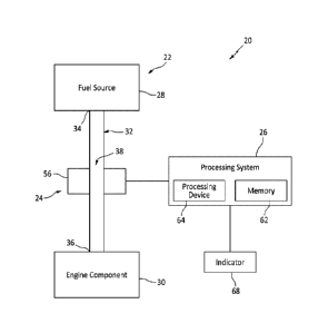
[0025] FIG. 1 is a schematic illustration of an assembly for an engine.
[0026] FIG. 2 is a schematic illustration of a fuel system in signal
communication with a
processing system.
[0027] FIG. 3 is a schematic illustration of the fuel system configured to
deliver fuel to
multiple components of the engine.
[0028] FIG. 4 is a schematic illustration of a sensor configured with a
fuel pump.
[0029] FIG. 5 is a schematic illustration of the sensor configured with a
fuel valve.
[0030] FIG. 6 is a schematic illustration of the sensor configured with a
fuel conduit.
[0031] FIG. 7 is a flow diagram of a method involving the engine and its
assembly.
[0032] FIG. 8 is a flow diagram of the fuel system configured with a
safety system and in
signal communication with the processing system.
[0033] FIGS. 9A and 9B are schematic illustrations of the fuel system
configured with
multiple fuel sources and in signal communication with the processing system.
[0034] FIG. 10 is a schematic illustration of the fuel system configured
with multiple
sensors in signal communication with the processing system.
[0035] FIG. 11 is a schematic illustration of a turbofan turbine engine
with which the
engine assembly may be included.
DETAILED DESCRIPTION
[0036] FIG. 1 illustrates an assembly 20 for an engine. For ease of
description, the
engine is described below as a gas turbine engine. This turbine engine may be
configured as a
turbofan turbine engine, a turbojet turbine engine, a turboprop turbine
engine, a turboshaft
turbine engine, an auxiliary power unit (APU) or an industrial gas turbine
engine configured for
generating power. The present disclosure, however, is not limited to the
foregoing exemplary
turbine engines. Furthermore, the present disclosure is not limited to turbine
engine applications.
4
Date Recue/Date Received 2022-07-15
For example, the engine assembly 20 may alternatively be configured for an
internal combustion
(IC) engine such as a piston engine or a rotary engine.
[0037] The engine assembly 20 of FIG. 1 includes a fuel system 22, a
sensor system 24
and a processing system 26 (e.g., a controller). The fuel system 22 includes a
fuel source 28, an
engine component 30 and a fuel circuit 32.
[0038] The fuel source 28 is configured to provide fuel for the fuel
system 22. The fuel
source 28 may also be configured to contain and hold a quantity of the fuel
prior to, during
and/or after engine operation. The fuel source 28, for example, may be
configured as a fuel
reservoir such as a container; e.g., a tank, a cylinder, a pressure vessel, a
bladder, etc. The fuel
source 28 of FIG. 1 includes a fuel source fuel outlet 34.
[0039] The engine component 30 may be, may include or may be part of any
component
or structure of the engine which may receive the fuel. The engine component 30
of FIG. 1, for
example, may be configured as a fuel injector. Alternatively, the engine
component 30 may be
configured as another component of the fuel system 22 such as a fuel manifold.
The present
disclosure, however, is not limited to the foregoing exemplary engine
components. The engine
component 30 of FIG. 1 includes an engine component fuel inlet 36.
[0040] The fuel circuit 32 is configured to direct (e.g., flow, pump
and/or otherwise
deliver) the fuel from the fuel source 28 to the engine component 30. The fuel
circuit 32 of FIG.
1, for example, is fluidly coupled with and between the fuel source 28 and the
engine component
30.
[0041] The fuel circuit 32 includes at least one flow passage 38. This
flow passage 38 of
FIG. 1 extends between and is fluidly coupled to the fuel source fuel outlet
34 and the engine
component fuel inlet 36.
[0042] Referring to FIG. 2, the flow passage 38 may be formed by one or
more fuel
conduits; e.g., pipes, hoses, etc. The flow passage 38 may also or
alternatively be formed by one
or more internal volumes (e.g., passages, cavities, spaces, bores, etc.)
within and/or through one
or more other components of the fuel system 22 / the engine. The flow passage
38 of FIG. 2, for
example, includes / is formed by a plurality of fuel conduits 40A-C (generally
referred to as
"40"), a fuel pump 42 and a fuel valve 44 (e.g., a shutoff valve, a flow
control valve, etc.). The
upstream conduit 40A extends between and is fluidly coupled to the fuel source
fuel outlet 34
and a fuel inlet 46 of the fuel pump 42. The midstream conduit 40B extends
between and is
Date Recue/Date Received 2022-07-15
fluidly coupled to a fuel outlet 48 of the fuel pump 42 and a fuel inlet 50 of
the fuel valve 44.
The downstream conduit 40C extends between and is fluidly coupled to a fuel
outlet 52 of the
fuel valve 44 and the engine component fuel inlet 36. With this arrangement,
the fuel pump 42
and/or the fuel valve 44 may regulate flow of the fuel within / directed
through the fuel circuit 32
from the fuel source 28 to the engine component 30.
[0043] For ease of description, the fuel circuit 32 is described above and
shown in FIG. 2
in a simplified form. In other embodiments, however, the fuel circuit 32 may
also include one or
more additional components such as, but not limited to, a fuel filter, a heat
exchanger (e.g., a
heater), an additional pump, an additional valve, a bypass passage, etc. The
fuel circuit 32 may
also or alternatively include more than one flow passage. The fuel circuit 32
of FIG. 3, for
example, includes a plurality of parallel flow passages 54A-C (generally
referred to as "54")
leading, for example, to multiple different engine components 30A-C (generally
referred to as
"30"); e.g., fuel injectors. Furthermore, while the fuel pump 42 is arranged
upstream of the fuel
valve 44 in FIGS. 2 and 3, the fuel valve 44 may alternatively be arranged
upstream of the fuel
pump 42; e.g., positions of the components 42 and 44 in FIGS. 2 and 3 may be
reversed. In still
other embodiments, the fuel pump 42 or the fuel valve 44 may be omitted and/or
replaced by
another fluid flow control device.
[0044] Referring again to FIG. 1, the sensor system 24 is configured to
observe the fuel
within the fuel system 22. The sensor system 24 of FIG. 1, for example,
includes a sensor 56;
e.g., a sensor probe. This sensor 56 of FIG. 1 is configured to measure a
parameter of the fuel
being directed through / within the fuel circuit 32 from the fuel source 28 to
the engine
component 30. Examples of the measured parameter include, but are not limited
to, pressure and
flowrate of the fuel at a certain location within the fuel circuit 32. The
sensor 56, for example,
may be configured as or otherwise include a fuel pressure sensor and/or a fuel
flow sensor.
[0045] The sensor 56 may be connected to, fluidly coupled inline with
and/or otherwise
arranged with the fuel circuit 32. For example, referring to FIG. 4, the
sensor 56 may be
arranged at (e.g., on, adjacent or proximate) an orifice 58 to the fuel pump
42; e.g., the fuel pump
fuel inlet 46 or the fuel pump fuel outlet 48 of FIG. 2. Referring to FIG. 5,
the sensor 56 may
alternatively be arranged at (e.g., on, adjacent or proximate) an orifice 60
to the fuel valve 44;
e.g., the fuel valve fuel inlet 50 or the fuel valve fuel outlet 52 of FIG. 2.
Referring to FIG. 6, the
sensor 56 may alternatively be arranged at an intermediate location along one
of the fuel
6
Date Recue/Date Received 2022-07-15
conduits 40, or at an end of one of the fuel conduits 40. Of course, the
sensor 56 may still also or
alternatively be arranged with another component of the fuel circuit 32. The
present disclosure
therefore is not limited to the foregoing exemplary sensor locations.
[0046] Referring to FIG. 1, the processing system 26 is in signal
communication with the
sensor system 24. The processing system 26 of FIG. 1, for example, is
hardwired to and/or
wirelessly coupled to the sensor 56. Referring to FIG. 2, the processing
system 26 may also be
in signal communication with the fuel system 22. The processing system 26 of
FIG. 2, for
example, is hardwired to and/or wirelessly coupled to the fuel pump 42 and/or
the fuel valve 44.
[0001] Referring to FIG. 1, the processing system 26 may be configured as
an onboard
engine controller; e.g., an electronic engine controller (EEC), an electronic
control unit (ECU), a
full-authority digital engine controller (FADEC), etc. The processing system
26 may be
implemented with a combination of hardware and software. The hardware may
include memory
62 and at least one processing device 64, which processing device 64 may
include one or more
single-core and/or multi-core processors. The hardware may also or
alternatively include analog
and/or digital circuitry other than that described above.
[0002] The memory 62 is configured to store software (e.g., program
instructions) for
execution by the processing device 64, which software execution may control
and/or facilitate
performance of one or more operations such as those described in the methods
below. The
memory 62 may be a non-transitory computer readable medium. For example, the
memory 62
may be configured as or include a volatile memory and/or a nonvolatile memory.
Examples of a
volatile memory may include a random access memory (RAM) such as a dynamic
random access
memory (DRAM), a static random access memory (SRAM), a synchronous dynamic
random
access memory (SDRAM), a video random access memory (VRAM), etc. Examples of a
nonvolatile memory may include a read only memory (ROM), an electrically
erasable
programmable read-only memory (EEPROM), a computer hard drive, etc.
[0047] FIG. 7 is a flow diagram of a method 700 involving (e.g.,
monitoring and/or
controlling) an engine. For ease of description, this method 700 is described
below with
reference to the fuel system 22 of FIG. 2 and the sensor system of FIG. 1. The
method 700,
however, may alternatively be performed for other fuel system configurations
and/or with other
sensor systems.
7
Date Recue/Date Received 2022-07-15
[0048] In step 702, the fuel is direct to the engine component 30 through
the fuel circuit
32. The processing system 26 of FIG. 2, for example, may signal the fuel pump
42 and the fuel
valve 44 to deliver the fuel to the engine component 30. More particularly,
the fuel pump 42
may draw the fuel from the fuel source 28 via the upstream conduit 40A, and
then pump that fuel
sequentially through the midstream conduit 40B, the open fuel valve 44 and the
downstream
conduit 40C to the engine component 30. The engine component 30 may provide
(e.g., inject)
the received fuel for mixing with (e.g., compressed) air and subsequent
combustion of the air-
fuel mixture within a combustion chamber 66.
[0049] The fuel may be a non-hydrocarbon fuel such as, but not limited to,
hydrogen
fuel. The fuel, for example, may be stored in the fuel source 28 (e.g., a
reservoir) as liquid
hydrogen or a mixture of liquid hydrogen and hydrogen gas. At least some or
all of the liquid
hydrogen may subsequently by vaporized within the fuel circuit 32 (e.g., via a
vaporizer; not
shown) to provide hydrogen gas (e.g., H2 gas) to the engine component 30. The
engine
component 30 may also or alternatively be configured as a vaporizer. The
engine component 30,
for example, may be configured to vaporize at least some or all of the liquid
hydrogen prior to or
while providing the hydrogen fuel for mixing with the air. Alternatively, the
hydrogen fuel may
be stored as substantially hydrogen gas within the fuel source 28. In such
embodiments, the fuel
pump 42 may be omitted where a pressure of the hydrogen (}12) gas stored in
the fuel source 28
is greater than pressure within the combustion chamber 66. Of course, various
other types of
non-hydrocarbon fuels are known in the art, and the present disclosure is not
limited to any
particular ones thereof. Furthermore, the present disclosure is not limited to
non-hydrocarbon
fuel applications. For example, the fuel may alternatively be or otherwise
include a more typical
hydrocarbon fuel such as, but not limited to, kerosene or jet fuel.
[0050] The fuel can be a highly combustible substance. This is
particularly true where
the fuel is or otherwise includes a gaseous fuel such as hydrogen (}12) gas.
Leakage of the fuel
from the fuel system 22 and its fuel circuit 32 may therefore be problematic.
Fuel leakage, for
example, may pose a safety hazard where the fuel may be ignited and combusted
outside of the
combustion chamber 66. Fuel leakage may also pose an environmental hazard. To
monitor for
possible fuel leakage from the fuel system 22, the sensor system 24 obverses
the fuel directed to
the engine component 30. The sensor 56, for example, measures a parameter of
the fuel directed
through (e.g., flowing within) the fuel circuit 32 from the fuel source 28 to
the engine component
8
Date Recue/Date Received 2022-07-15
30. In step 704, the sensor 56 generates sensor data (e.g., a voltage signal)
indicative of the
measured parameter, and provides the sensor data to the processing system 26.
[0051] In step 706, the sensor data is monitored to identify (e.g.,
detect) a fuel leak in the
fuel system 22. The processing system 26, for example, processes the sensor
data. The
processing system 26 may compare a value (referred to as a measured value)
corresponding to
the measured parameter to a value (referred to as an expected value)
corresponding to an
expected parameter for the fuel at the sensor location, where the expected
value may be stored as
a predetermined value for a particular set of operating conditions in the
memory 62. The
processing system 26 may thereby compare what is actually occurring within the
fuel circuit 32
at the sensor location (the measured parameter) to what is expected to occur
within the fuel
circuit 32 at the sensor location (the expected parameter) for a particular
mode of engine
operation. Where the measured value is different (e.g., less or greater) than
the expected value,
the processing system 26 may determine a fuel leak is present in the fuel
system 22.
[0052] Where the measured value is less than the expected value (e.g., by
at least a
threshold amount), the processing system 26 may determine a fuel leak is
present within the fuel
system 22 and, more particularly, within the fuel circuit 32 upstream of the
sensor 56. For
example, where the sensor 56 measures a fuel pressure within the fuel circuit
32 of X-2 Bar at
the sensor location but expects the fuel pressure within the fuel circuit 32
to be X Bar at the
sensor location, the processing system 26 may determine that 2 Bar of the fuel
is leaking from
the fuel circuit 32 upstream of the sensor 56. The measured pressure of the
fuel at the sensor
location may be less than expected because some of the fuel (e.g., 2 Bar of
the fuel) may be
leaking out of the fuel circuit 32 prior to reaching the sensor location
thereby driving the
measured fuel pressure lower than expected. A similar comparison may be made
where the
sensor measures flowrate (or another parameter) of the fuel within the fuel
circuit 32 at the
sensor location. For example, where the measured fuel flowrate is less than
expected, the
processing system 26 may determine some of the fuel is leaking out of the fuel
circuit 32 prior to
reaching the sensor location thereby driving the measured fuel flowrate lower
than expected.
[0053] Referring to FIG. 1, following identification of the fuel leak, the
processing
system 26 may signal an indicator 68 to provide an indication to an engine
operator; e.g., a pilot
where the engine is configured in an aircraft propulsion system. This
indication is provided to
communicate to the engine operator that the fuel system 22 and its fuel
circuit 32 has a fuel leak
9
Date Recue/Date Received 2022-07-15
so that the engine operator may take appropriate action. The indication may be
a visual
indication where, for example, the indicator 68 is configured as or otherwise
includes a warning
light, a gauge, a screen or otherwise. The indication may also or
alternatively be an audible
indication where, for example, the indicator 68 is configured as or otherwise
includes an audio
speaker, a bell or an alarm.
[0054] Referring to FIG. 2, following identification of the fuel leak, the
processing
system 26 may also or alternatively signal a flow regulator 70 of the fuel
system 22 to (e.g.,
significantly) reduce or stop the flow of fuel through the fuel circuit 32 to
the engine component
30. This flow regulator 70 may be configured as or otherwise include the fuel
pump 42 and/or
the fuel valve 44. The processing system 26, for example, may signal the fuel
pump 42 to stop
pumping the fuel. The processing system 26 may also or alternatively signal
the fuel valve 44 to
close, thereby fluidly decoupling the fuel source 28 from the engine component
30.
[0055] Referring to FIG. 8, following identification of the fuel leak, the
processing
system 26 may also or alternatively signal a safety system 72 to purge some or
all of the fuel out
of the fuel circuit 32. The safety system 72 of FIG. 8, for example, includes
a fluid reservoir 74
and a (e.g., 3-way) fluid valve 76. The fluid reservoir 74 may be a container
that holds a safety
fluid such as, but not limited to, an inert fluid; e.g., inert gas. The fluid
valve 76 is configured to
selectively fluidly couple the fluid reservoir 74 to the fuel circuit 32 (and
decouple the fuel
source 28 from the fuel circuit 32) such that the safety fluid may flow
through and purge the fuel
from the fuel circuit 32 when the fluid valve 76 is actuated.
[0056] Referring to FIGS. 9A and 9B, following identification of the fuel
leak, the
processing system 26 may also or alternatively switch the engine to operate on
another fuel. For
example, where the engine is operating on a non-hydrocarbon fuel such as
hydrogen gas when
the fuel leak is identified, the engine may be switched to operate on a
hydrocarbon fuel such as
kerosene or jet fuel. The fuel system 22 of FIG. 9A, for example, includes a
plurality of fuel
sources 28A and 28B (generally referred to as "28") and a plurality of
parallel fuel circuits 32A
and 32B (generally referred to as "32") which provide respective (e.g.,
different) fuels to the
engine component 30. When one of the fuel circuits (e.g., 32A or 32B) is shut
off (e.g., via its
valve 44 and/or operation of its pump 42 and/or otherwise), the other one of
the fuel circuits
(e.g., 32B or 32A) may be activated (e.g., via its valve 44 and/or operation
of its pump 42 and/or
otherwise). In another example, referring to FIG. 9B, the fuel system 22 may
include a (e.g., 3-
Date Recue/Date Received 2022-07-15
way) valve 78 configured to selectively fluidly couple one of multiple fuel
sources (e.g., 28A or
28B) to the fuel circuit 32. The present disclosure, of course, is not limited
to the foregoing
exemplary multi-fuel source arrangements.
[0057] The method 700 is described above as detecting / identifying the
fuel leak during
operation of the engine. However, in other embodiments, a fuel leak may also
or alternatively be
identified while the engine is non-operational. For example, the sensor system
24 may observe
fuel flow within the fuel circuit 32 and then provide the sensor data to the
processing system 26.
Where the measured value (e.g., a positive value) corresponding to the
measured parameter is
higher than the expected value (e.g., here a zero value) corresponding to the
expected parameter,
the processing system 26 may identify presence of a fuel leak in the fuel
circuit 32. For example,
where the sensor 56 measures a positive fuel pressure within the fuel circuit
32 when there
should be a zero fuel pressure, there is likely a fuel leak in a control
element upstream of the
sensor location. Similarly, where the sensor 56 measures a positive fuel
flowrate within the fuel
circuit 32 when there should be a zero fuel flowrate, again there is likely a
fuel leak in a control
element upstream of the sensor location.
[0058] The sensor system 24 is described above as including the single
sensor 56.
However, in other embodiments, the sensor system 24 may include a plurality of
the sensors
56A-C (generally referred to as "54") as shown, for example, in FIG. 10. Each
of these sensors
56 may be configured to measure a common or different parameter (e.g., fuel
pressure, fuel
flowrate, etc.) of the fuel directed within the fuel circuit 32 and provide
corresponding sensor
data to the processing system 26. The processing system 26 may process this
sensor data to
identify a fuel leak as described above. For example, the processing system 26
may identify
presence of a fuel leak where a measured value corresponding to a parameter
measured by any
one of the sensors (e.g., 56A, 56B or 56C) is different (e.g., less or
greater) than expected.
Alternatively, the processing system 26 may identify presence of a fuel leak
where a measured
value corresponding to a parameter measured by any two or more (or all) of the
sensors (e.g.,
56A and 56B, 56A and 56C, 56B and 56C, or 56A-C) is different (e.g., less or
greater) than
expected.
[0059] Where the sensor system 24 includes the multiple sensors 56, the
processing
system 26 may be adapted to identify a sensor malfunction. For example, where
the upstream
sensor (e.g., 56A) measures a parameter different than expected, but multiple
of the downstream
11
Date Recue/Date Received 2022-07-15
sensors (e.g., 56B and 56C) measures parameters that are expected, the
processing system 26
may determine that the upstream sensor (e.g., 56A) is malfunctioning.
[0060] Where the sensor system 24 includes the multiple of sensors 56, the
processing
system 26 may identify a region in the fuel circuit 32 where the fuel leak is
located. For
example, where the measured parameters from all of the sensors 56 are
different than expected,
the processing system 26 may determine a fuel leak is at least located
upstream of those sensors
56; e.g., upstream of the sensor 56A. In another example, where the measured
parameter from
one of the downstream sensors (e.g., 56B or 56C) is different than expected
but the measured
parameter from one of the upstream sensors (e.g., 56A or 56B) is as expected,
the processing
system 26 may determine a fuel leak is at least located fluidly between the
upstream and the
downstream sensors 56.
[0061] The fuel pump 42 is described above as a main fuel pump between the
fuel source
28 and the engine component 30. However, in other embodiments, the fuel system
22 and its
fuel circuit 32 may include at least one additional fuel pump. In such
embodiments, the fuel
pump 42 may still be configured as the main (e.g., upstream) fuel pump.
Alternatively, the fuel
pump 42 may be configured as a boost pump; e.g., a downstream fuel pump. One
or each of
these fuel pumps may be configured with a respective sensor 56 at one of its
orifices (e.g., its
inlet or its outlet) as described above.
[0062] As described above, each sensor 56 may be arranged at (e.g., on,
adjacent or
proximate) an orifice (e.g., an inlet or an outlet) of a flow regulation
element (e.g., the fuel pump
42 or the fuel valve 44). With such an arrangement, the expected parameter of
the fuel may be
easier to predict. For example, where the sensor 56 is positioned at the inlet
or the outlet of the
pump 42 or the valve 44, a pressure and a flowrate at those locations may be
readily predicted
assuming normal fuel system operation. The present disclosure, however, is not
limited to any
particular sensor locations.
[0063] FIG. 11 illustrates an example of the engine with which the engine
assembly
components described above may be configured. This turbine engine is
configured as a turbofan
gas turbine engine 80. The turbine engine 80 of FIG. 11 extends along a
centerline 82 of the
turbine engine 80 between an upstream airflow inlet 84 and a downstream
airflow exhaust 86.
The turbine engine 80 includes a fan section 88, a compressor section 89, a
combustor section 90
and a turbine section 91.
12
Date Recue/Date Received 2022-07-15
[0064] The fan section 88 includes a fan rotor 94. The compressor section
89 includes a
compressor rotor 95. The turbine section 91 includes a high pressure turbine
(HPT) rotor 96 and
a low pressure turbine (LPT) rotor 97, where the LPT rotor 97 is configured as
a power turbine
rotor. Each of these rotors 94-97 includes a plurality of rotor blades
arranged circumferentially
around and connected to one or more respective rotor disks.
[0065] The fan rotor 94 is connected to the LPT rotor 97 through a low
speed shaft 100.
The compressor rotor 95 is connected to the HPT rotor 96 through a high speed
shaft 102. The
low speed shaft 100 extends through a bore of the high speed shaft 102 between
the fan rotor 94
and the LPT rotor 97.
[0066] During operation, air enters the turbine engine 80 through the
airflow inlet 84.
This air is directed through the fan section 88 and into a core flowpath 104
and a bypass
flowpath 106. The core flowpath 104 extends sequentially through the engine
sections 89-91;
e.g., an engine core. The air within the core flowpath 104 may be referred to
as "core air". The
bypass flowpath 106 extends through a bypass duct, which bypasses the engine
core. The air
within the bypass flowpath 106 may be referred to as "bypass air".
[0067] The core air is compressed by the compressor rotor 95 and directed
into the (e.g.,
annular) combustion chamber 66 of a (e.g., annular) combustor 108 in the
combustor section 90.
Fuel is injected into the combustion chamber 66 via one or more fuel injectors
110 (e.g., the
engine components 30) and mixed with the compressed core air to provide a fuel-
air mixture.
This fuel-air mixture is ignited and combustion products thereof flow through
and sequentially
cause the HPT rotor 96 and the LPT rotor 97 to rotate. The rotation of the HPT
rotor 96 drives
rotation of the compressor rotor 95 and, thus, compression of air received
from an inlet into the
core flowpath 104. The rotation of the LPT rotor 97 drives rotation of the fan
rotor 94, which
propels bypass air through and out of the bypass flowpath 106. The propulsion
of the bypass air
may account for a significant portion (e.g., a majority) of thrust generated
by the turbine engine
80.
[0068] While various embodiments of the present disclosure have been
described, it will
be apparent to those of ordinary skill in the art that many more embodiments
and
implementations are possible within the scope of the disclosure. For example,
the present
disclosure as described herein includes several aspects and embodiments that
include particular
features. Although these features may be described individually, it is within
the scope of the
13
Date Recue/Date Received 2022-07-15
present disclosure that some or all of these features may be combined with any
one of the aspects
and remain within the scope of the disclosure. Accordingly, the present
disclosure is not to be
restricted except in light of the attached claims and their equivalents.
14
Date Recue/Date Received 2022-07-15