Note: Descriptions are shown in the official language in which they were submitted.
MOUNTING ASSEMBLY MOUNTABLE TO A WIRE LATTICE
FIELD
[0001] The present disclosure relates to a mounting assembly, and in
particular, a mounting
assembly that is securable to a wire lattice of a wire barrier system or a
wire containment
system.
BACKGROUND
[0002] To avoid clutter, and to organize objects, such as tools, toys,
organizing boxes and bins,
equipment, and the like, the objects may be hung from a wire lattice, for
example, of a wire
barrier system such as a wire panel, wire mesh, wire grid, wire shelving, or a
wire fence, such
as a chain link fence, or of a wire containment system, such as a wire cage,
wire box, wire bin,
or wire storage room. A mounting assembly, including a bracket, may be hung
from the wire
lattice, and the object may be hung from the mounting assembly, such that the
object is hung
from the wire lattice via the mounting assembly.
[0003] Unfortunately, while existing mounting assemblies are hangable from the
wire lattice,
they are not securable to the wire lattice. Accordingly, existing mounting
assemblies may be
unintentionally disconnected from the wire lattice, for example, by a user
that knocks into the
mounting assembly, or while an object is being removed from the mounting
assembly. Such
unintentional disconnection of the existing mounting assemblies from the wire
lattice may
require re-hanging of the mounting assembly on the. In addition, since
existing mounting
assemblies are not securable to the wire lattice, the weight of the object to
the hung from the
mounting assembly may be limited, to reduce the risk of damage to the wire
lattice, the bracket,
or the surrounding environment if the object unintentionally falls from the
mounting assembly
due to unintentional disconnection of the mounting assembly from the wire
lattice.
SUMMARY
[0004] In one aspect, there is provided a bracket configured to be connected
to a wire lattice,
the wire lattice defined by a plurality of wires, the plurality of wires
including an upper wire and a
lower wire, wherein the lower wire is disposed below the upper wire, the
bracket comprising: an
upper bracket-defined connection counterpart defining a hook, wherein: the
hook is configured
for hooking onto the upper wire such that the hook and the upper wire are co-
operatively
1
Date Recue/Date Received 2022-07-19
disposed in a hooked configuration, and with effect that the bracket is
hanging from the wire
lattice; and a lower bracket-defined connection counterpart, disposed below
the upper bracket-
defined connection counterpart, and defining a lower rotation-opposing
configuration for
disposition relative to the lower wire; wherein: the spacing between the upper
bracket-defined
connection counterpart and the lower bracket-defined connection counterpart is
adjustable
between at least a rotation resistant spacing and a rotation permissive
spacing; while: (i) the
hook and the upper wire are disposed in the hooked configuration, and (ii) the
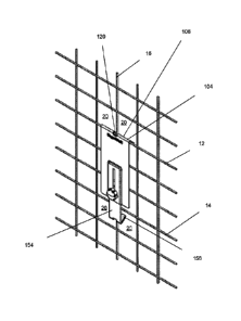
spacing between
the upper bracket-defined connection counterpart and the lower bracket-defined
connection
counterpart is the rotation-resistant spacing, the lower rotation-opposing
configuration is
disposed relative to the lower wire, such that the lower rotation-opposing
configuration opposes
rotation of the bracket, relative to the wire lattice, in a first direction,
and also opposes rotation of
the bracket, relative to the wire lattice in a second direction, wherein the
first direction is
opposite to the second direction; and while: (i) the hook and the upper wire
are disposed in the
hooked configuration, and (ii) the spacing between the upper bracket-defined
connection
counterpart and the lower bracket-defined connection counterpart is the
rotation-permissive
spacing, the lower rotation-opposing configuration is disposed relative to the
lower wire, such
that: (i) there is an absence of opposing of rotation of the bracket, relative
to the wire lattice, by
the lower rotation-opposing configuration, in the first direction, and (ii)
there is an absence of
opposing of rotation of the bracket, relative to the wire lattice by the lower
rotation-opposing
configuration, in the second direction.
[0005] In another aspect, there is provided a bracket configured to be
connected to a wire
lattice, the wire lattice defined by a plurality of wires, the plurality of
wires including an upper
wire and a lower wire, wherein the lower wire is disposed below the upper
wire, the kit
comprising: a bracket member, defining an upper bracket-defined connection
counterpart
defining a hook, wherein: the hook is configured for hooking onto the upper
wire such that the
hook and the upper wire are co-operatively disposed in a hooked configuration,
and with effect
that the bracket is hanging from the wire lattice; and a connection
counterpart-defining
configuration, releasably coupled to the bracket member, and defining a lower
bracket-defined
connection counterpart, disposed below the upper bracket-defined connection
counterpart, the
lower bracket-defined connection counterpart defining a lower rotation-
opposing configuration
for disposition relative to the lower wire; wherein: the spacing between the
upper bracket-
defined connection counterpart and the lower bracket-defined connection
counterpart is
adjustable between at least a rotation resistant spacing and a rotation
permissive spacing;
2
Date Recue/Date Received 2022-07-19
while: (i) the hook and the upper wire are disposed in the hooked
configuration, and (ii) the
spacing between the upper bracket-defined connection counterpart and the lower
bracket-
defined connection counterpart is the rotation-resistant spacing, the lower
rotation-opposing
configuration is disposed relative to the lower wire, such that the lower
rotation-opposing
configuration opposes rotation of the bracket, relative to the wire lattice,
in a first direction, and
also opposes rotation of the bracket, relative to the wire lattice in a second
direction, wherein
the first direction is opposite to the second direction; and while: (i) the
hook and the upper wire
are disposed in the hooked configuration, and (ii) the spacing between the
upper bracket-
defined connection counterpart and the lower bracket-defined connection
counterpart is the
rotation-permissive spacing, the lower rotation-opposing configuration is
disposed relative to the
lower wire, such that: (i) there is an absence of opposing of rotation of the
bracket, relative to
the wire lattice, by the lower rotation-opposing configuration, in the first
direction, and (ii) there is
an absence of opposing of rotation of the bracket, relative to the wire
lattice by the lower
rotation-opposing configuration, in the second direction.
[0006] In another aspect, there is provided kit for a bracket configured to be
connected to a wire
lattice, the wire lattice defined by a plurality of wires, the plurality of
wires including an upper
wire and a lower wire, wherein the lower wire is disposed below the upper
wire, the kit
comprising: a bracket member, defining an upper bracket-defined connection
counterpart
defining a hook, wherein: the hook is configured for hooking onto the upper
wire such that the
hook and the upper wire are co-operatively disposed in a hooked configuration,
and with effect
that the bracket is hanging from the wire lattice; and a connection
counterpart-defining
configuration, releasably couplable to the bracket member, and defining a
lower bracket-defined
connection counterpart, the lower bracket-defined connection counterpart
defining a lower
rotation-opposing configuration for disposition relative to the lower wire;
wherein, while the
bracket member and the connection counterpart-defining configuration are
releasably coupled,
the lower bracket-defined connection counterpart is disposed below the upper
bracket-defined
connection counterpart, and the bracket is defined, and: the spacing between
the upper bracket-
defined connection counterpart and the lower bracket-defined connection
counterpart is
adjustable between at least a rotation resistant spacing and a rotation
permissive spacing;
while: (i) the hook and the upper wire are disposed in the hooked
configuration, and (ii) the
spacing between the upper bracket-defined connection counterpart and the lower
bracket-
defined connection counterpart is the rotation-resistant spacing, the lower
rotation-opposing
configuration is disposed relative to the lower wire, such that the lower
rotation-opposing
3
Date Recue/Date Received 2022-07-19
configuration opposes rotation of the bracket, relative to the wire lattice,
in a first direction, and
also opposes rotation of the bracket, relative to the wire lattice in a second
direction, wherein
the first direction is opposite to the second direction; and while: (i) the
hook and the upper wire
are disposed in the hooked configuration, and (ii) the spacing between the
upper bracket-
defined connection counterpart and the lower bracket-defined connection
counterpart is the
rotation-permissive spacing, the lower rotation-opposing configuration is
disposed relative to the
lower wire, such that: (i) there is an absence of opposing of rotation of the
bracket, relative to
the wire lattice, by the lower rotation-opposing configuration, in the first
direction, and (ii) there is
an absence of opposing of rotation of the bracket, relative to the wire
lattice by the lower
rotation-opposing configuration, in the second direction.
[0007] Other aspects will be apparent from the description and drawings
provided herein.
BRIEF DESCRIPTION OF DRAWINGS
[0008] In the figures, which illustrate example embodiments,
[0009] Figure 1 is front perspective view of a bracket of a mounting assembly;
[0010] Figure 2 is a rear perspective view of the bracket of Figure 1;
[0011] Figure 3 is a front view of the bracket of Figure 1;
[0012] Figure 4 is a rear view of the bracket of Figure 1;
[0013] Figure 5 is a side view of the bracket of Figure 1;
[0014] Figure 6 is a front perspective view of a mounting assembly, including
a load supporter
connected to the bracket of Figure 1;
[0015] Figure 7 is a rear perspective view of the mounting assembly of Figure
6;
[0016] Figure 8 is a front view of the mounting assembly of Figure 6;
[0017] Figure 9 is a rear view of the mounting assembly of Figure 6;
[0018] Figure 10 is a side view of the mounting assembly of Figure 6;
4
Date Recue/Date Received 2022-07-19
[0019] Figure 11 is a front perspective view of the mounting assembly of
Figure 6 and a wire
lattice;
[0020] Figure 12 is a side view of the mounting assembly and wire lattice of
Figure 11;
[0021] Figure 13 is a front view of the mounting assembly and the wire lattice
of Figure 11;
[0022] Figure 14 is a front perspective view of the bracket of Figure 1 hung
from a wire lattice;
[0023] Figure 15 is a rear perspective view of the bracket of Figure 1 hung
from a wire lattice;
[0024] Figure 16 is a front view of the bracket of Figure 1 hung from a wire
lattice;
[0025] Figure 17 is a rear view of the bracket of Figure 1 hung from a wire
lattice;
[0026] Figure 18 is a side view of the bracket of Figure 1 hung from a wire
lattice;
[0027] Figure 19 is a front perspective view of the bracket of Figure 1
secured to a wire lattice;
[0028] Figure 20 is a rear perspective view of the bracket of Figure 1 secured
to a wire lattice;
[0029] Figure 21 is a front view of the bracket of Figure 1 secured to a wire
lattice;
[0030] Figure 22 is a rear view of the bracket of Figure 1 secured to a wire
lattice;
[0031] Figure 23 is a side view of the bracket of Figure 1 secured to a wire
lattice;
[0032] Figure 24 is a front perspective view of the mounting assembly of
Figure 6 secured to a
wire lattice;
[0033] Figure 25 is a rear perspective view of the mounting assembly of Figure
6 secured to a
wire lattice;
[0034] Figure 26 is a front view of the mounting assembly of Figure 6 secured
to a wire lattice;
[0035] Figure 27 is a rear view of the mounting assembly of Figure 6 secured
to a wire lattice;
[0036] Figure 28 is a side view of the mounting assembly of Figure 6 secured
to a wire lattice;
[0037] Figure 29 is a front perspective view of the mounting assembly of
Figure 6 hung from a
wire lattice;
Date Recue/Date Received 2022-07-19
[0038] Figure 30 is a rear perspective view of the mounting assembly of Figure
6 hung from a
wire lattice;
[0039] Figure 31 is a front view of the mounting assembly of Figure 6 hung
from a wire lattice;
[0040] Figure 32 is a side view of the mounting assembly of Figure 6 hung from
a wire lattice;
[0041] Figure 33 is a front perspective view of the mounting assembly of
Figure 6 secured to a
wire lattice;
[0042] Figure 34 is a rear perspective view of the mounting assembly of Figure
6 secured to a
wire lattice;
[0043] Figure 35 is a front view of the mounting assembly of Figure 6 secured
to a wire lattice;
[0044] Figure 36 is a side view of the mounting assembly of Figure 6 secured
to a wire lattice.
[0045] Figure 37 is front perspective view of another embodiment of the
mounting assembly;
[0046] Figure 38 is a rear perspective view of the mounting assembly of Figure
37;
[0047] Figure 39 is a rear perspective view of the mounting assembly of Figure
37 in a retracted
configuration;
[0048] Figure 40 is a front view of the mounting assembly of Figure 37;
[0049] Figure 41 is a rear view of the mounting assembly of Figure 37
[0050] Figure 42 is a side view of the mounting assembly of Figure 37 in a
retracted
configuration;
[0051] Figure 43 is an enlarged view of the portion of the mounting assembly
of Figure 42, the
portion identified by the window A shown in Figure 42;
[0052] Figure 44 is an enlarged view of the portion of the mounting assembly
of Figure 42, the
portion identified by the window B shown in Figure 42;
[0053] Figure 45 is a top view of the mounting assembly of Figure 37;
[0054] Figure 46 is a bottom view of the mounting assembly of Figure 37;
6
Date Recue/Date Received 2022-07-19
[0055] Figure 47 is a front perspective view of the mounting assembly of
Figure 37 secured to a
wire lattice;
[0056] Figure 48 is a rear perspective view of the mounting assembly of Figure
37 secured to a
wire lattice.
[0057] Figure 49 is front perspective view of another embodiment of the
mounting assembly;
[0058] Figure 50 is a rear perspective view of the mounting assembly of Figure
49;
[0059] Figure 51 is a front view of the mounting assembly of Figure 49;
[0060] Figure 52 is a rear view of the mounting assembly of Figure 49
[0061] Figure 53 is a left side view of the mounting assembly of Figure 49;
[0062] Figure 54 is a right side view of the mounting assembly of Figure 49;
[0063] Figure 55 is a top view of the mounting assembly of Figure 49;
[0064] Figure 56 is a bottom view of the mounting assembly of Figure 49;
[0065] Figure 57 is a front perspective view of the mounting assembly of
Figure 49 secured to a
wire lattice;
[0066] Figure 58 is a rear perspective view of the mounting assembly of Figure
49 secured to a
wire lattice.
DETAILED DESCRIPTION
[0067] Figure 1 to Figure 5 depicts an example embodiment of a mounting
assembly 100. In
some embodiments, for example, the mounting assembly 100 includes a bracket
102 and a load
supporter 300.
[0068] The bracket 102 is configured to be connected to a wire lattice 10, for
example, of a wire
barrier system such as a wire panel, wire mesh, wire grid, wire shelving, or a
wire fence, such
as a chain link fence, or of a wire containment system, such as a wire cage,
wire box, wire bin,
or wire storage room. In some embodiments, for example, the wire lattice 10 is
defined by a
plurality of wires, the plurality of wires including an upper wire 12 and a
lower wire 14. In some
7
Date Recue/Date Received 2022-07-19
embodiments, for example, the lower wire 14 is offset from the upper wire 12.
In some
embodiments, for example, the lower wire 14 is disposed below the upper wire
12.
[0069] In some embodiments, for example, the wire lattice 10 includes an
intersecting wire 16.
In some embodiments, for example, the intersecting wire 16 engages at least
one of the upper
wire 12 and the lower wire 14. In some embodiments, for example, the
intersecting wire 16
engages both of the upper wire 12 and the lower wire 14.
[0070] In some embodiments, for example, the upper wire 12 extends along a
first axis, the
lower wire 14 extends along a second axis, and the intersecting wire 16
extends along a third
axis. In some embodiments, for example, the first axis and the second axis are
parallel. In
some embodiments, for example, the first axis and the second axis are non-
parallel. In some
embodiments, for example, the first axis and the third axis are non-parallel.
In some
embodiments, for example, the second axis and the third axis are non-parallel.
In some
embodiments, for example, the first axis and the third axis are perpendicular.
In some
embodiments, for example, the second axis and the third axis are
perpendicular.
[0071] In some embodiments, for example, the wire lattice 10 includes a
plurality of openings
20, as depicted in Figure 11. In some embodiments, for example, the plurality
of openings 20 is
defined between the plurality of wires of the wire lattice 10.
[0072] In some embodiments, for example, as depicted in Figure 11 to Figure
28, the wire
lattice 10 is configurable in an upright configuration, wherein the wires of
the wire lattice 10
extend horizontally and vertically, such as the wire lattice 10 of a wire cage
or a wire storage
room. In some embodiments, for example, while the lattice 10 is configured in
the upright
configuration, the upper wire 12 and the lower wire 14 extend in a horizontal
direction, and the
intersecting wire 16 extends in a vertical direction. In some embodiments, for
example, the
openings 20 of the wire lattice 10 in the upright configuration are square-
shaped or rectangular-
shaped.
[0073] In some embodiments, for example, as depicted in Figure 29 to Figure
36, the wire
lattice 10 is configurable in an angled configuration, wherein the wires of
the wire lattice 10
extend angularly, for example, such as the wire lattice 10 of a chain link
fence. In some
embodiments, for example, while the lattice 10 is configured in the angled
configuration, the
upper wire 12 extends along an axis that defines an acute angle with a
horizontal axis, wherein
the acute angle has a minimum value of at least 1 degree. In some embodiments,
for example,
8
Date Recue/Date Received 2022-07-19
while the lattice 10 is configured in the angled configuration, the lower wire
14 extends along an
axis that defines an acute angle with a horizontal axis, wherein the acute
angle has a minimum
value of at least 1 degree. In some embodiments, for example, while the
lattice 10 is configured
in the angled configuration, the intersecting wire 16 extends along an axis
that defines an acute
angle with a horizontal axis, wherein the acute angle has a minimum value of
at least 1 degree,
and wherein: (i) the axis of extension of the intersecting wire 16 and the
axis of extension of the
upper wire 12 are non-parallel, and (ii) the axis of extension of the
intersecting wire 16 and the
axis of extension of the lower wire 14 are non-parallel. In some embodiments,
for example, the
openings 20 of the wire lattice 10 in the upright configuration are diamond-
shaped or rhombus-
shaped.
[0074] In some embodiments, for example, the bracket 102 includes an upper
bracket-defined
connection counterpart 104 and a lower bracket-defined connection counterpart
154. As
depicted in Figure 1 to Figure 5, in some embodiments, for example, the upper
bracket-defined
connection counterpart 104 and the lower bracket-defined connection
counterpart 154 are
disposed at opposite ends of the bracket 102. In some embodiments, for
example, while the
bracket 102 is disposed in an operating configuration, the lower bracket-
defined connection
counterpart 154 is disposed below the upper bracket-defined connection
counterpart 104. In
some embodiments, for example, the upper bracket-defined connection
counterpart 104 is
configured to co-operate with the wire lattice 10 such that the bracket 102 is
hangable from the
wire lattice 10, and the lower bracket-defined connection counterpart 104 is
configured to co-
operate with the wire lattice 10 such that, while the bracket 102 is hanging
from the wire lattice
10, the bracket 102 is securable to the wire lattice 10.
[0075] The upper bracket-defined connection counterpart 104 defines a hook
106. In some
embodiments, for example, the hook 106 is configured to receive at least a
portion of the upper
wire 12. In some embodiments, for example, the hook 106 is configured for
hooking onto the
upper wire 12 such that the hook 106 and the upper wire 12 are co-operatively
disposed in a
hooked configuration, as depicted, for example, in Figure 13 to Figure 36, and
with effect that
the assembly 100, for example, the bracket 102, is hanging from the wire
lattice 10, for
example, from the upper wire 12. As depicted in Figure 1 to Figure 5, in some
embodiments, for
example, the hook 106 includes a hook member 108 that extends in a downward
direction. In
some embodiments, for example, the bracket 102 defines an upper channel 110.
The upper
channel 110 is configured to receive at least a portion of the upper wire 12
for hanging the
assembly 100, for example, the bracket 102, from the upper wire 12.
9
Date Recue/Date Received 2022-07-19
[0076] The lower bracket-defined connection counterpart 154 defines a lower
rotation-opposing
configuration 156 for disposition relative to the lower wire 14. In some
embodiments, for
example, the lower rotation-opposing configuration 156 defines a hook. In some
embodiments,
for example, the lower rotation-opposing configuration 156 and the lower wire
14 are co-
operatively configured to secure the connection of the assembly 100 and the
wire lattice 10
while the assembly 100, for example, the bracket 102, is hanging from the wire
lattice 10. As
depicted in Figure 1 to Figure 5, in some embodiments, for example, the lower
rotation-
opposing configuration 156 includes a lower rotation-opposing configuration
member 158 that
extends in an upward direction. In some embodiments, for example, the bracket
102 defines a
lower channel 160. The lower channel 160 is configured to receive at least a
portion of the
lower wire 14 for securing the connection of the assembly 100 and the wire
lattice 10 while the
assembly 100 is hanging from the wire lattice 10.
[0077] In some embodiments, for example, the spacing between the upper bracket-
defined
connection counterpart 104 and the lower bracket-defined connection
counterpart 154 is
adjustable between at least a rotation resistant spacing, as depicted in
Figure 19 to Figure 23,
Figure 24 to Figure 28, and Figure 33 to Figure 36, and a rotation permissive
spacing, as
depicted in Figure 14 to Figure 18 and Figure 29 to Figure 32. As depicted, in
some
embodiments, for example, the spacing between the upper bracket-defined
connection
counterpart 104 and the lower bracket-defined connection counterpart 154,
while the spacing
between the upper bracket-defined connection counterpart 104 and the lower
bracket-defined
connection counterpart 154 is the rotation permissive spacing, is greater than
the spacing
between the upper bracket-defined connection counterpart 104 and the lower
bracket-defined
connection counterpart 154, while the spacing between the upper bracket-
defined connection
counterpart 104 and the lower bracket-defined connection counterpart 154 is
the rotation
resistant spacing. In some embodiments, for example, the spacing between the
upper bracket-
defined connection counterpart 104 and the lower bracket-defined connection
counterpart 154,
while the spacing between the upper bracket-defined connection counterpart 104
and the lower
bracket-defined connection counterpart 154 is the rotation permissive spacing,
is less than the
spacing between the upper bracket-defined connection counterpart 104 and the
lower bracket-
defined connection counterpart 154, while the spacing between the upper
bracket-defined
connection counterpart 104 and the lower bracket-defined connection
counterpart 154 is the
rotation resistant spacing.
Date Recue/Date Received 2022-07-19
[0078] In some embodiments, for example, while: (i) the hook 106 and the upper
wire 12 are
disposed in the hooked configuration, and (ii) the spacing between the upper
bracket-defined
connection counterpart 104 and the lower bracket-defined connection
counterpart 154 is the
rotation-resistant spacing, the lower rotation-opposing configuration 156 is
disposed relative to
the lower wire 14, such that the lower rotation-opposing configuration 156
opposes rotation of
the bracket 102, relative to the wire lattice 10, in a first direction, and
also opposes rotation of
the bracket 102, relative to the wire lattice 10 in a second direction,
wherein the first direction is
opposite to the second direction. In some embodiments, for example, while: (i)
the hook 106
and the upper wire 12 are disposed in the hooked configuration, and (ii) the
spacing between
the upper bracket-defined connection counterpart 104 and the lower bracket-
defined connection
counterpart 154 is the rotation-resistant spacing, the lower rotation-opposing
configuration 156
is disposed relative to the lower wire 14, such that the lower rotation-
opposing configuration 156
opposes rotation of the bracket 102, relative to the wire lattice 10, in the
first direction, and also
opposes rotation of the bracket 102, relative to the wire lattice 10, in the
second direction, the
connection of the assembly 100 and the wire lattice 10 is established.
[0079] In some embodiments, for example, the first direction is a direction of
rotation towards
the wire lattice 10, for example, towards a plane in which the wire lattice 10
is disposed, and the
second direction is a direction of rotation away from the wire lattice 10, for
example, away from
a plane in which the wire lattice 10 is disposed.
[0080] In some embodiments, for example, while: (i) the hook 106 and the upper
wire 12 are
disposed in the hooked configuration, and (ii) the spacing between the upper
bracket-defined
connection counterpart 104 and the lower bracket-defined connection
counterpart 154 is the
rotation-resistant spacing, at least a portion of the lower wire 14 is
received in the lower channel
160, such that the lower rotation-opposing configuration 156 and the lower
wire 14 are co-
operatively configured to oppose rotation of the bracket 102, relative to the
wire lattice 10, in a
first direction, and also opposes rotation of the bracket 102, relative to the
wire lattice 10, in a
second direction, wherein the first direction is opposite to the second
direction.
[0081] In some embodiments, for example, while: (i) the hook 106 and the upper
wire 12 are
disposed in the hooked configuration, and (ii) the spacing between the upper
bracket-defined
connection counterpart 104 and the lower bracket-defined connection
counterpart 154 is the
rotation-resistant spacing, the bracket 102 and the wire lattice 10 are co-
operatively configured
in a rotation-resistant configuration, wherein the lower rotation-opposing
configuration 156 is
11
Date Recue/Date Received 2022-07-19
disposed relative to the lower wire 14, such that the lower rotation-opposing
configuration 156
opposes rotation of the bracket 102, relative to the wire lattice 10, in a
first direction, and also
opposes rotation of the bracket 102, relative to the wire lattice 10 in a
second direction, wherein
the first direction is opposite to the second direction. In some embodiments,
for example, while
the bracket 102 and the wire lattice 10 are co-operatively configured in the
rotation-resistant
configuration, at least a portion of at least the lower wire 14 is disposed in
the lower channel
160, such that the lower rotation-opposing configuration 156 and the lower
wire 14 are co-
operatively configured to oppose rotation of the bracket 102, relative to the
wire lattice 10, in a
first direction, and also opposes rotation of the bracket 102, relative to the
wire lattice 10, in a
second direction, wherein the first direction is opposite to the second
direction.
[0082] In some embodiments, for example, while: (i) the hook 106 and the upper
wire 12 are
disposed in the hooked configuration, and (ii) the spacing between the upper
bracket-defined
connection counterpart 104 and the lower bracket-defined connection
counterpart 154 is the
rotation-permissive spacing, the lower rotation-opposing configuration 156 is
disposed relative
to the lower wire 14, such that: (i) there is an absence of opposing of
rotation of the bracket 102,
relative to the wire lattice 10, by the lower rotation-opposing configuration
156, in the first
direction, and (ii) there is an absence of opposing of rotation of the bracket
102, relative to the
wire lattice 10, by the lower rotation-opposing configuration 156, in the
second direction.
[0083] In some embodiments, for example, while: (i) the hook 106 and the upper
wire 12 are
disposed in the hooked configuration, and (ii) the spacing between the upper
bracket-defined
connection counterpart 104 and the lower bracket-defined connection
counterpart 154 is the
rotation-permissive spacing, the lower wire 14 is disposed outside of the
lower channel 160,
such that: (i) there is an absence of opposing of rotation of the bracket 102,
relative to the wire
lattice 10, by the lower rotation-opposing configuration 156, in the first
direction, and (ii) there is
an absence of opposing of rotation of the bracket 102, relative to the wire
lattice 10, by the lower
rotation-opposing configuration 156, in the second direction.
[0084] In some embodiments, for example, while: (i) the hook 106 and the upper
wire 12 are
disposed in the hooked configuration, and (ii) the spacing between the upper
bracket-defined
connection counterpart 104 and the lower bracket-defined connection
counterpart 154 is the
rotation-permissive spacing, the bracket 102 and the wire lattice 102 are co-
operatively
configured in the rotation-permissive configuration, wherein the lower
rotation-opposing
configuration 156 is disposed relative to the lower wire 14, such that: (i)
there is an absence of
12
Date Recue/Date Received 2022-07-19
opposing of rotation of the bracket 102, relative to the wire lattice 10, by
the lower rotation-
opposing configuration 156, in the first direction, and (ii) there is an
absence of opposing of
rotation of the bracket 102, relative to the wire lattice 10, by the lower
rotation-opposing
configuration 156, in the second direction. In some embodiments, for example,
while the
bracket 102 and the wire lattice 102 are co-operatively configured in the
rotation-permissive
configuration, the lower wire 14 is disposed outside of the lower channel 160,
such that: (i) there
is an absence of opposing of rotation of the bracket 102, relative to the wire
lattice 10, by the
lower rotation-opposing configuration 156, in the first direction, and (ii)
there is an absence of
opposing of rotation of the bracket, relative to the wire lattice 10, by the
lower rotation-opposing
configuration 156, in the second direction.
[0085] In some embodiments, for example, the bracket 102 is configurable in a
fixed
configuration and an adjustable configuration. In the fixed configuration,
there is an absence of
adjustability of the spacing between the upper bracket-defined connection
counterpart 104 and
the lower bracket-defined connection counterpart 154. In the adjustable
configuration, spacing
between the upper bracket-defined connection counterpart 104 and the lower
bracket-defined
connection counterpart 154 is adjustable, for example, between at least the
rotation resistant
spacing and the rotating permissive spacing.
[0086] In some embodiments, for example, in the adjustable configuration,
spacing between the
upper bracket-defined connection counterpart 104 and the lower bracket-defined
connection
counterpart 154 is adjustable such that the assembly 100 is hangable and
securable to a first
pair of wires, the first pair of wires including an upper wire and a lower
wire, and also to a
second pair of wires, the second pair of wires including an upper wire and a
lower wire.
[0087] In some embodiments, for example, the first pair of wires is spaced
apart by a first
spacing distance, and the second pair of wires is spaced apart by a second
spacing distance.
In some embodiments, for example, the first spacing distance and the second
spacing distance
is the same. In some embodiments, for example, the first spacing distance and
the second
spacing distance is different. In some embodiments, for example, the first
spacing distance is
greater than the second spacing distance. In some embodiments, for example,
the first spacing
distance is less than the second spacing distance.
[0088] In some embodiments, for example, the first spacing distance of the
first pair of wires is
2 inches. In some embodiments, for example, the second spacing distance of the
second pair
13
Date Recue/Date Received 2022-07-19
of wires is 4 inches. In some embodiments, for example, the first spacing
distance of the first
pair of wires is 6 inches. In some embodiments, for example, the second
spacing distance of
the second pair of wires is 8 inches. In some embodiments, for example, the
first spacing
distance of the first pair of wires is 10 inches. In some embodiments, for
example, the second
spacing distance of the second pair of wires is 12 inches.
[0089] In some embodiments, for example, adjusting of the spacing between the
upper bracket-
defined connection counterpart 104 and the lower bracket-defined connection
counterpart 154
from a spacing corresponding to the first spacing, to a spacing corresponding
to the second
spacing, is effected by displacement of the lower bracket-defined connection
counterpart 154
towards the upper bracket-defined connection counterpart 104. In some
embodiments, for
example, adjusting of the spacing from the spacing corresponding to the second
spacing, to the
spacing corresponding to the first spacing, is effected by displacement of the
lower bracket-
defined connection counterpart 154 away from the upper bracket-defined
connection
counterpart 104.
[0090] In some embodiments, for example, adjusting of the spacing between the
upper bracket-
defined connection counterpart 104 and the lower bracket-defined connection
counterpart 154
from the spacing corresponding to the first spacing, to the spacing
corresponding to the second
spacing, is effected by displacement of the lower bracket-defined connection
counterpart 154
away from the upper bracket-defined connection counterpart 104. In some
embodiments, for
example, adjusting of the spacing from the spacing corresponding second
spacing, to the
spacing corresponding to the first spacing, is effected by displacement of the
lower bracket-
defined connection counterpart 154 towards the upper bracket-defined
connection counterpart
104.
[0091] In some embodiments, for example, the first pair of wires and the
second pair of wires
are defined on the same wire lattice 10.
[0092] In some embodiments, for example, wherein the first pair of wires and
the second pair of
wires are defined on the same wire lattice 10, the first pair of wires is
defined by a first upper
wire and a first lower wire, and the second pair of wires is defined by a
second upper wire and a
second lower wire, wherein the first upper wire and the second upper wire are
different wires,
and the first lower wire and the second lower wire are different wires.
14
Date Recue/Date Received 2022-07-19
[0093] In some embodiments, for example, wherein the first pair of wires and
the second pair of
wires are defined on the same wire lattice 10 the first pair of wires is
defined by a first upper
wire and a first lower wire, and the second pair of wires is defined by the
first upper wire and a
second lower wire, wherein the first lower wire and the second lower wire are
different wires.
[0094] In some embodiments, for example, wherein the first pair of wires and
the second pair of
wires are defined on the same wire lattice 10 the first pair of wires is
defined by a first upper
wire and a first lower wire, and the second pair of wires is defined by a
second upper wire and
the first lower wire, wherein the first upper wire and the second upper wire
are different wires.
[0095] In some embodiments, for example, the first pair of wires is defined on
a wire lattice 10,
and the second pair of wires is defined on a second wire lattice 10 that is
different from the first
wire lattice 10.
[0096] In some embodiments, for example, as depicted in Figure 1, the bracket
102 includes a
bracket member 1021. In some embodiments, for example, upper bracket-defined
connection
counterpart 104 is defined by the bracket member 1021. In some embodiments,
for example,
the bracket member 1021 includes a flange 103, defining a front surface 105
and a rear surface
107 that is disposed on an opposite side of the flange 103 relative to the
front surface 105. In
some embodiments, for example, the front surface 105 defines a surface
configured for being
visible while the assembly 100 is hung from the wire lattice 10. In some
embodiments, for
example, the rear surface 107 defines a lattice-opposing surface configured
for opposing the
wire lattice 10 while the assembly 100 is hung from the wire lattice 10. In
some embodiments,
for example, the front surface 105 is the front surface 105 of the bracket
102.
[0097] In some embodiments, for example, the flange 103 and the upper bracket-
defined
connection counterpart 104 are connected. In some embodiments, for example,
the bracket
member 1021, including the flange 103 and the upper bracket-defined connection
counterpart
104, is of unitary one piece construction.
[0098] In some embodiments, for example, while the hooked configuration is
established, the
flange 103 and the wire lattice 10 are disposed in opposing relationship. In
some embodiments,
for example, while the hooked configuration is established, the flange 103 and
the wire lattice 10
are disposed in abutting engagement. In some embodiments, for example, while
the hooked
configuration is established, the flange 103 is bearing against the wire
lattice 10.
Date Recue/Date Received 2022-07-19
[0099] As depicted in Figure 1 to Figure 5, in some embodiments, for example,
the hook
member 108 extends in a direction towards the center of the flange 103. In
some embodiments,
for example, the flange 103 and the hook member 108 are co-operatively
configured to define
the upper channel 110. In some embodiments, for example, the upper channel 110
is defined
between the flange 103 and the hook member 108.
[00100] As depicted in Figure 5, the hook member 108 defines a hook member
surface
112 that is disposed in opposing relationship to the rear surface 107. In some
embodiments, for
example, the acute angle defined between the hook member surface 112 and the
rear surface
107 has a minimum value of at least 10 degrees. In some embodiments, for
example, the acute
angle defined between the hook member surface 112 and the rear surface 107 has
a value of
45 degrees. In some embodiments, for example, the size of the upper channel
110 is based on
the acute angle defined between the hook member surface 112 and the rear
surface 107. In
some embodiments, for example, the size of the upper channel 110 increases as
the acute
angle defined between the hook member surface 112 and the rear surface 107 is
increased.
[00101] In some embodiments, for example, the upper bracket-defined
connection
counterpart 104, for example, the hook 106, defines an internal curved surface
113 that extends
between the rear surface 107 and the hook member surface 112. In some
embodiments, for
example, the internal curved surface 113 is configured for disposition in
contact engagement
with the upper wire 12 while the hook 106 and the upper wire 12 are co-
operatively disposed in
the hooked configuration. In some embodiments, for example, the radius of
curvature of the
internal curved surface 113 has a minimum value of at least 1/64". In some
embodiments, for
example, the radius of curvature of the internal curved surface 113 has a
value of 1/32". In
some embodiments, for example, while the bracket 102 is hanging from the upper
wire 12, the
upper wire 12 that is disposed in the upper channel 110 is disposed in contact
engagement with
the internal curved surface 113. In some embodiments, for example, the
connection between
the bracket 102 and the upper wire 12, for example, the hanging of the bracket
102 from the
upper wire 12, is improved while the upper wire 12 is disposed in contact
engagement with the
internal curved surface 113, which reduces the risk of unintentional
disconnection of the
assembly 100 from the wire lattice 10.
[00102] In some embodiments, for example, while the bracket 102 is hanging
from the
upper wire 12, the radius of the upper wire 12 is such that contact engagement
of the upper wire
12 with the internal curved surface 113 is absent. In some embodiments, for
example, while the
16
Date Recue/Date Received 2022-07-19
bracket 102 is hanging from the upper wire 12, the radius of the upper wire 12
is greater than
the radius of curvature of the internal curved surface 113 such that contact
engagement of the
upper wire 12 with the internal curved surface 113 is absent. In such
embodiments, for
example, the upper wire 12 is disposed in contact engagement with the hook
member surface
112 and the rear surface 107 while the bracket 102 is hanging from the upper
wire 12.
[00103] As depicted in Figure 1 to Figure 5, in some embodiments, for
example, the
lower rotation-opposing configuration member 158 extends in a direction
towards the center of
the flange 103. In some embodiments, for example, the flange 103 and the lower
rotation-
opposing configuration member 158 are co-operatively configured to define the
lower channel
160. In some embodiments, for example, the lower channel 160 is defined
between the flange
103 and the lower rotation-opposing configuration member 158.
[00104] As depicted in Figure 5, the lower rotation-opposing configuration
member 158
defines a lower rotation-opposing configuration member surface 162 that is
disposed in
opposing relationship to the rear surface 107. In some embodiments, for
example, the acute
angle defined between the lower rotation-opposing configuration member surface
162 and the
rear surface 107 has a minimum value of at least 10 degrees. In some
embodiments, for
example, the acute angle defined between the lower rotation-opposing
configuration member
surface 162 and the rear surface 107 has a value of 45 degrees. In some
embodiments, for
example, the size of the lower channel 160 is based on the acute angle defined
between the
lower rotation-opposing configuration member surface 162 and the rear surface
107. In some
embodiments, for example, the size of the lower channel 160 increases as the
acute angle
defined between the lower rotation-opposing configuration member surface 162
and the rear
surface 107 is increased.
[00105] In some embodiments, for example, the lower bracket-defined
connection
counterpart 154, for example, the lower rotation-opposing configuration 156,
defines an internal
curved surface 163 that extends between the rear surface 107 and the lower
rotation-opposing
configuration member surface 162. In some embodiments, for example, the
internal curved
surface 163 is configured for disposition in contact engagement with the lower
wire 14 while: (i)
the hook 106 and the upper wire 12 are co-operatively disposed in a hooked
configuration, and
(ii) the spacing between the upper bracket-defined connection counterpart 104
and the lower
bracket-defined connection counterpart 154 is a rotation-resistant spacing. In
some
embodiments, for example, the radius of curvature of the internal curved
surface 163 has a
17
Date Recue/Date Received 2022-07-19
minimum value of at least 1/64". In some embodiments, for example, the radius
of curvature of
the internal curved surface 163 has a value of 1/32". In some embodiments, for
example, while
the assembly 100 is hanging from the wire lattice 10, and while the connection
of the assembly
100 to the wire lattice 10 is secured by the co-operative configuration of the
lower rotation-
opposing configuration 156 and the lower wire 14, the lower wire 14 that is
disposed in the lower
channel 160 is disposed in contact engagement with the internal curved surface
163. In some
embodiments, for example, the securing of the connection between the assembly
100 and the
wire lattice 10 is improved while the lower wire 14 is disposed in contact
engagement with the
internal curved surface 163, which reduces the risk of unintentional
disconnection of the lower
rotation-opposing configuration 156 from the lower wire 14 or unintentional
displacement of the
assembly 100 relative to the wire lattice.
[00106] In some embodiments, for example, while the connection of the
assembly 100
and the wire lattice 10 is secured via co-operative configuration of the lower
rotation-opposing
configuration 156 and the lower wire 14, the radius of the lower wire 14 is
such that contact
engagement of the lower wire 14 with the internal curved surface 163 is
absent. In some
embodiments, for example, while the connection of the assembly 100 and the
wire lattice 10 is
secured via co-operative configuration of the lower rotation-opposing
configuration 156 and the
lower wire 14, the radius of the lower wire 14 is greater than the radius of
curvature of the
internal curved surface 163 such that contact engagement of the lower wire 14
with the internal
curved surface 163 is absent. In such embodiments, for example, the lower wire
14 is disposed
in contact engagement with the lower rotation-opposing configuration member
surface 162 and
the rear surface 107 while the connection of the assembly 100 and the wire
lattice 10 is secured
via co-operative configuration of the lower rotation-opposing configuration
156 and the lower
wire 14.
[00107] In some embodiments, for example, the bracket 102 comprises a
connection
counterpart-defining configuration 200. In some embodiments, for example, the
bracket
member 1021 is releasably couplable to the connection counterpart-defining
configuration 200.
In some embodiments, for example, the connection counterpart-defining
configuration 200 is
releasably couplable to the flange 103 of the bracket member 1021. In some
embodiments, for
example, the releasable coupling of the bracket member 1021 and the connection
counterpart-
defining configuration 200 is effected by the releasable coupling of the
flange 103 and the
connection counterpart-defining configuration 200. In some embodiments, for
example, while
the bracket member 1021 is releasably coupled to the connection counterpart-
defining
18
Date Recue/Date Received 2022-07-19
configuration 200, the bracket 102 is defined. In some embodiments, for
example, the
releasable coupling of the bracket member 1021 and the connection counterpart-
defining
configuration 200 is such that the connection counterpart-defining
configuration 200 slidably
coupled to the bracket member 1021, for example, to the flange 103.
[00108] As depicted in Figure 1 and Figure 2, the lower bracket-defined
connection
counterpart 154 is defined by the connection counterpart-defining
configuration 200. As
depicted, in some embodiments, for example, the connection counterpart-
defining configuration
200 includes an intermediate member 202. In some embodiments, for example, the
lower
bracket-defined connection counterpart 154 is connected to the intermediate
member 202. In
some embodiments, for example, the connection counterpart-defining
configuration 200, which
includes the lower bracket-defined connection counterpart 154 and the
intermediate member
202, is of unitary one piece construction.
[00109] The bracket member 1021 is releasably couplable to the connection
counterpart-
defining configuration 200, such that, while the bracket member 1021 and the
connection
counterpart-defining configuration 200 are releasably coupled, the relative
displacement is
effectible between the bracket member 1021 and the connection counterpart-
defining
configuration 200. In some embodiments, for example, adjusting of the spacing
between the
upper bracket-defined connection counterpart 104 and the lower bracket-defined
connection
counterpart 154 is effectible by relative displacement between the bracket
member 1021 and
the connection counterpart-defining configuration 200. In some embodiments,
for example, the
relative displacement effectible between the bracket member 1021 and the
connection
counterpart-defining configuration 200inc1ude5 sliding displacement.
[00110] In some embodiments, for example, the displacement of the
connection
counterpart-defining configuration 200, relative to the bracket member 1021 is
along a
displacement axis that is parallel to the longitudinal axis of the bracket
member 1021. In some
embodiments, for example, the displacement axis is parallel to a vertical
axis.
[00111] In some embodiments, for example, the assembly 100 includes a
locking
mechanism 204. In some embodiments, for example, the locking mechanism 204
includes a
rotatable head 204A, and a threaded rod or stud that is releasably couplable
to the rotatable
head 204A via the threading at a first end of the threaded stud, and that is
also connected to the
connection counterpart-defining configuration 200, for example, the
intermediate member 202,
19
Date Recue/Date Received 2022-07-19
via welding, at the second end of the threaded stud. As depicted in Figure 1
and Figure 2, the
intermediate member 202 is disposed on a first side of the flange 103 (e.g.
rear side of the
flange 103), and the rotatable head 204A is disposed on a second side of the
flange 103 that is
opposite the first side (e.g. front side of the flange 103).
[00112] In some embodiments, for example, the locking mechanism 204 is
configured to
effect frictional engagement between the flange 103 and the intermediate
member 202, and
further configured to defeat the frictional engagement between the flange 103,
and the
intermediate member 202.
[00113] The bracket member 1021, the connection counterpart-defining
configuration
200, and the locking mechanism 204 are co-operatively configured to transition
between a
displacement-effective configuration and a displacement ineffective
configuration. In the
displacement effective configuration, the bracket member 1021, the connection
counterpart-
defining configuration 200, and the locking mechanism 204 are co-operatively
configured such
that there is an absence of frictional engagement of the flange 103 and the
intermediate
member 202 by the locking mechanism 204, such that the bracket 102 is disposed
in the
adjustable configuration, wherein the connection counterpart-defining
configuration 200 is
displaceable relative to the bracket member 1021. In the displacement
ineffective configuration,
the bracket member 1021, the connection counterpart-defining configuration
200, and the
locking mechanism 204 are co-operatively configured such that frictional
engagement of the
flange 103 and the intermediate member 202 is effected by the locking
mechanism 204, such
that the bracket 102 is disposed in the fixed configuration, wherein relative
displacement
between the connection counterpart-defining configuration 200 and the bracket
member 1021 is
resisted.
[00114] In some embodiments, for example, the bracket member 1021, the
connection
counterpart-defining configuration 200, and the locking mechanism 204 are
transitionable from
the displacement effective configuration to the displacement-ineffective
configuration in
response to actuation of the locking mechanism 204, for example, by rotation
of the head 204A
in a first direction, for example, a clockwise direction. In some embodiments,
for example, in
response to actuation of the locking mechanism 204 in the first direction, a
force is applied by
the locking mechanism 204 to the connection counterpart-defining configuration
200 to displace
the connection counterpart-defining configuration 200 towards the flange 103,
such that at the
Date Recue/Date Received 2022-07-19
intermediate member 202 becomes disposed in frictional engagement with the
flange 103, with
effect that the bracket 102 becomes disposed in the fixed configuration.
[00115] In some embodiments, for example, the bracket member 1021, the
connection
counterpart-defining configuration 200, and the locking mechanism 204 are
transitionable from
the displacement ineffective configuration to the displacement effective
configuration in
response to actuation of the locking mechanism 204, for example, by rotation
of the head 204A
in a second direction that is opposite the first direction, for example, a
counter clockwise
direction. In some embodiments, for example, in response to actuation of the
locking
mechanism 204 in the second direction, a force is applied by the locking
mechanism 204 to the
connection counterpart-defining configuration 200 to displace the connection
counterpart-
defining configuration 200 away from the flange 103, such that frictional
engagement between
the flange 103 and the intermediate member 202 is defeated, with effect that
the bracket 102
becomes disposed in the adjustable configuration.
[00116] In some embodiments, for example, the bracket 102 includes a slot
208. As
depicted, in some embodiments, for example, the slot 208 is a linear slot. As
depicted, the slot
208 is defined by the flange 103. The slot 208 extends from a bottom end of
the flange 103. As
depicted in Figure 1 to Figure 3, the slot 208 extends from the bottom end of
the flange 103 to
the middle of the flange 103. In some embodiments, for example, the length of
the slot 208 is
generally half the length of the flange 103. In some embodiments, for example,
the length of the
slot 208 is greater than or less than half the length of the flange 103. The
slot 208 is configured
to receive at least a portion of the threaded stud of the locking mechanism
204, such that the
threaded stud extends through the slot 208, such that, while the rotatable
head 204A is
releasably coupled to the threaded stud via the threading, the bracket member
1021 and the
connection counterpart-defining configuration 200 are releasably coupled, and
the intermediate
member 202 is disposed on the first side of the flange 103 (e.g. rear side of
the flange 103), and
the rotatable head 204A is disposed on the second side of the flange 103 that
is opposite the
first side (e.g. front side of the flange 103). In some embodiments, for
example, the slot 208
limits displacement of the threaded stud of the locking mechanism 204, and
therefore, limits the
displacement of the connection counterpart-defining configuration 200,
relative to the bracket
member 1021. In some embodiments, for example, the slot 208 defines an upper
terminal end
that limits further upward displacement of the threaded stud of the locking
mechanism 204 and
therefore, limits further upward displacement of the connection counterpart-
defining
configuration 200, relative to the bracket member 1021. In some embodiments,
for example,
21
Date Recue/Date Received 2022-07-19
the slot 208 defines a lower terminal end that limits further downward
displacement of the
threaded stud of the locking mechanism 204 and therefore, limits further
downward
displacement of the connection counterpart-defining configuration 200,
relative to the bracket
member 1021.
[00117] In some embodiments, for example, as depicted in Figure 1, the
flange 103
includes a raised portion 205 that defines a recess 206 for receiving at least
a portion of the
connection counterpart-defining configuration 200, in particular, for
receiving at least a portion of
the intermediate member 202. While the bracket member 1021 and the connection
counterpart-
defining configuration 200 are releasably coupled, at least a portion of the
intermediate member
202 is received in the recess 206.
[00118] In some embodiments, for example, the flange 103 includes the
recess 206 for
receiving at least a portion of the intermediate member 202, while the bracket
member 1021
and the connection counterpart-defining configuration 200 are releasably
coupled, such that,
while the bracket member 1021 and the connection counterpart-defining
configuration 200 are
releasably coupled, the intermediate member 202 is not disposed rearwardly of
the rear surface
107 of the flange 103. In some embodiments, for example, it is desirable for
the intermediate
member 202 to not be disposed rearwardly of the rear surface 107 of the flange
103, while the
bracket member 1021 and the connection counterpart-defining configuration 200
are releasably
coupled, as disposition of the intermediate member 202 rearwardly of the rear
surface 107,
while the bracket member 1021 and the connection counterpart-defining
configuration 200 are
releasably coupled, interferes with the securing of the mounting assembly 100
to the wire lattice
10.
[00119] In some embodiments, for example, the recess 206 and the
connection
counterpart-defining configuration 200 are co-operatively configured such that
the connection
counterpart-defining configuration 200 is slidable, relative to the bracket
member 1021 while the
at least a portion of the connection counterpart-defining configuration 200,
for example, the
intermediate member 202, is received in the recess 206.
[00120] As depicted, in some embodiments, for example, the slot 208 is
defined by the
raised portion 205.
[00121] In some embodiments, for example, the bracket 102 is configurable
in a retracted
configuration, an extended configuration, and an intermediate configuration.
In the retracted
22
Date Recue/Date Received 2022-07-19
configuration, the spacing distance between the upper bracket-defined
connection counterpart
104 and the lower bracket-defined connection counterpart 154 is a minimum
spacing distance.
In some embodiments, for example, the bracket member 1021, the locking
mechanism 204, the
slot 208, and the connection counterpart-defining configuration 200 are co-
operatively
configured such that, while the locking mechanism 204, for example, the
threaded stud, is
disposed at the upper terminal end of the slot 208, the bracket 102 is
disposed in the retracted
configuration. In some embodiments, for example, while the bracket 102 is
disposed in the
retracted configuration, the connection counterpart-defining configuration 200
is entirely
disposed in the recess 206, for example, as depicted in Figure 39. In the
extended
configuration, the spacing distance between the upper bracket-defined
connection counterpart
104 and the lower bracket-defined connection counterpart 154 is a maximum
spacing distance.
In some embodiments, for example, the bracket member 1021, the locking
mechanism 204, the
slot 208, and the connection counterpart-defining configuration 200 are co-
operatively
configured such that, while the locking mechanism 204, for example, the
threaded stud, is
disposed at the lower terminal end of the slot 208, the bracket 102 is
disposed in the extended
configuration. In some embodiments, for example, while the bracket 102 is
disposed in the
extended configuration, at least a portion of the connection counterpart-
defining configuration
200, for example, the portion including the lower bracket-defined connection
counterpart 154, is
disposed outside of the recess 206. In the intermediate configuration, the
spacing distance
between the upper bracket-defined connection counterpart 104 and the lower
bracket-defined
connection counterpart 154 is between the minimum spacing distance and the
maximum
spacing distance. In some embodiments, for example, the bracket member 1021,
the locking
mechanism 204, the slot 208, and the connection counterpart-defining
configuration 200 are co-
operatively configured such that, while the locking mechanism 204, for
example, the threaded
stud, is disposed between the upper terminal end and the lower terminal end of
the slot 208, the
bracket 102 is disposed in the intermediate configuration.
[00122] In some embodiments, for example, the minimum and maximum spacing
distances between the upper bracket-defined connection counterpart 104 and the
lower bracket-
defined connection counterpart 154 is defined based on: 1) the length of the
slot 208,2) the
position of the slot 208 on the flange 103, and 2) the length of the
intermediate member 202.
[00123] In some embodiments, for example, the bracket member 1021 and the
connection counterpart-defining configuration 200 are co-operatively
configured such that the
minimum spacing distance between the upper bracket-defined connection
counterpart 104 and
23
Date Recue/Date Received 2022-07-19
the lower bracket-defined connection counterpart 154 is 1 inch, and the
maximum spacing
distance between the upper bracket-defined connection counterpart 104 and the
lower bracket-
defined connection counterpart 154 is 12 inches.
[00124] In some embodiments, for example, for a given length of the slot
208, a decrease
in length of the intermediate member 202 decreases the minimum and maximum
spacing
distances between the upper bracket-defined connection counterpart 104 and the
lower bracket-
defined connection counterpart 154, and an increase in length of the
intermediate member 202
increases the minimum and maximum spacing distances between the upper bracket-
defined
connection counterpart 104 and the lower bracket-defined connection
counterpart 154.
[00125] In some embodiments, for example, for a given length of the
intermediate
member 202, and for a slot 208 that extends from the bottom of the flange 103
in an upward
direction, a decrease in length of the slot 208 increases the minimum spacing
distance between
the upper bracket-defined connection counterpart 104 and the lower bracket-
defined connection
counterpart 154, but does not increase the maximum spacing distance between
the upper
bracket-defined connection counterpart 104 and the lower bracket-defined
connection
counterpart 154, and an increase in length of the slot 208 decreases the
minimum spacing
distance between the upper bracket-defined connection counterpart 104 and the
lower bracket-
defined connection counterpart 154, but does not decrease the maximum spacing
distance
between the upper bracket-defined connection counterpart 104 and the lower
bracket-defined
connection counterpart 154.
[00126] In some embodiments, for example, as depicted in Figure 6 to
Figure 10, the
mounting assembly 100 includes a load supporter 300. In some embodiments, for
example, the
load supporter 300 is connected to the bracket 102, for example, to the flange
103, by welding,
mechanical fasteners, adhesives, and the like. The load supporter 300 includes
a load-
supporting portion 302, the load-supporting portion 302 configured to support
a load, such as
tires, storage boxes and bins, tools, sports equipment, outdoor equipment,
lumber, clothes,
appliances, pool accessories and toys, and the like. As depicted in Figure 6
to Figure 10, in
some embodiments, for example the load supporter 300 includes two hooks. In
some
embodiments, for example, the load supporter 300 includes one hook. In some
embodiments,
for example, the load supporter 300 includes a ring from which a load is hung.
In some
embodiments, for example, the load supporter 300 includes a ring from which a
load is received.
In some embodiments, for example, the load supporter 300 includes a basket in
which a load is
24
Date Recue/Date Received 2022-07-19
received. In some embodiments, for example, the load supporter 300 includes a
rod on which a
load is supported, for example, a rod to hang clothes.
[00127] In some embodiments, for example, as depicted in Figure 6 to
Figure 10, the
load-supporting portion 302 extends outwardly, relative to the front surface
105 of the bracket
102. In some embodiments, for example, the load-supporting portion 302 extends
outwardly,
relative to the front surface 105 of the bracket 102, along a plane that is
perpendicular to a
plane defined by the front surface 105 of the bracket 102. In some
embodiments, for example,
the load-supporting portion 302 extends in a direction along an axis 304 that
traverses a plane
defined by the front surface 105 of the bracket 102. In some embodiments, for
example, the
traversing of the plane defined by the front surface 105 of the bracket 102 by
the extension axis
of the load-supporting portion 302 is such that the axis 304 is normal to the
plane defined by the
front surface 105 of the bracket 102. In some embodiments, for example, the
traversing of the
plane defined by the front surface 105 of the bracket 102 by the extension
axis 304 of the load-
supporting portion 302 is such that the axis 304 is angled relative to the
plane defined by the
front surface 105 of the bracket 102, the axis 304 and the plane defining an
acute angle (e.g.
the load supporting portion 302 extends from the flange 103 in a direction to
the left or to the
right). In some embodiments, for example, the acute angle defined between the
axis 304 and
the plane defined by the front surface 105 of the bracket 102 has a minimum
value of at least 60
degrees.
[00128] In some embodiments, for example, the load-supporting portion 302
extends
outwardly and in an upward direction, relative to the front surface 105 of the
bracket 102. In this
respect, in some embodiments, for example, the axis 304 is angled upwardly
relative to a
normal axis of the plane defined by the front surface 105 of the bracket 102,
the axis 304 and
the normal axis defining an acute angle therebetween. In some embodiments, for
example, the
acute angle defined between the axis 304 and the normal axis of the plane
defined by the front
surface 105 of the bracket 102 has a minimum value of at least 1 degree.
[00129] In some embodiments, for example, the load-supporting portion 302
extends
outwardly and in a downward direction, relative to the front surface 105 of
the bracket 102. In
this respect, in some embodiments, for example, the axis 304 is angled
downwardly relative to a
normal axis of the plane defined by the front surface 105 of the bracket 102,
the axis 304 and
the normal axis defining an acute angle therebetween. In some embodiments, for
example, the
Date Recue/Date Received 2022-07-19
acute angle defined between the axis 304 and the normal axis of the plane
defined by the front
surface 105 of the bracket 102 has a maximum value of 5 degrees.
[00130] In some embodiments, for example, the load supporter 300 includes
a load-
retaining portion 306, configured to resist removal of a load that is
supported by the load-
supporting portion 302. As depicted in Figure 6 to Figure 10, the load-
retaining portion 306 is
angled relative to the load-supporting portion 302. In some embodiments, for
example, the
acute angle defined between load supporting portion 302 and the load-retaining
portion 306 has
a minimum value of at least 5 degrees. Due to the angled disposition of the
load-retaining
portion 306, relative to the load-supporting portion 302, while a load is
supported by the load-
supporting portion 302, if the load is displaced in a direction that is
parallel to the axis 304, the
load will engage the load-retaining portion 306, which will resist further
displacement of the load
in the direction that is parallel to the axis 304. To remove the load, the
direction of displacement
of the load is to be changed, in particular, to a direction along an axis of
extension of the load-
retaining portion 306, which is angled relative to the axis 304.
[00131] In some embodiments, for example, the mounting assembly 100
includes one
bracket 102, and a load supporter 300, for example, one or more hooks,
baskets, hanging rods,
and the like, that is connected to the bracket 102. In such embodiments, for
example, while the
mounting assembly 100 is secured to a wire lattice 10, the load that is
supported by the load
supporter 300 is distributed to the wire lattice 10 via the bracket 102.
[00132] In some embodiments, for example, the mounting assembly 100
includes more
than one bracket 102, and a load supporter 300, for example, one or more
hooks, baskets,
hanging rods, and the like, that is connected to the brackets 102. In such
embodiments, for
example, while the mounting assembly 100 is secured to a wire lattice 10, the
load that is
supported by the load supporter 300 is distributed to the wire lattice 10 via
the plurality of
brackets 102.
[00133] In some embodiments, for example, the mounting assembly 100
includes more
than one bracket 102, and for each one of the brackets 102, independently, the
bracket 102 is
connected to a load supporter 300, for example, one or more hooks, baskets,
hanging rods, and
the like. In such embodiments, for example, while the mounting assembly 100 is
secured to a
wire lattice 10, the load that is supported by the load supporters 300 is
distributed to the wire
lattice 10 via the plurality of brackets 102.
26
Date Recue/Date Received 2022-07-19
[00134] In some embodiments, for example, the width of the upper bracket-
defined
connection counterpart 104 is wider than the width of the opening 20 of the
wire lattice,
measured along a horizontal axis. In a wire lattice configured in an upright
configuration, the
width of the opening 20 is the distance between two adjacent vertical sides of
the opening 20,
wherein the adjacent vertical sides are defined by adjacent vertical wires. In
a wire lattice
configured in an angled configuration, the width of the opening 20 is the
distance between two
opposing corners of the opening 20, wherein, for each corner of the opening
20, the corner is
defined by a first wire and a second wire that intersects the first wire. For
example, the upper
wire 12 and the intersecting wire 16 intersect to define one of the corners of
an opening of a
wire lattice 10 configured in an angled configuration, as depicted in Figure
29. In some
embodiments, for example, one or more wires of the wire lattice 10 interferes
with hanging the
bracket 102 at a desired portion of the wire lattice 10.
[00135] In some embodiments, for example, the upper bracket-defined
connection
counterpart 104 defines a wire-receiving space 120, for example, an upper wire
receiving space
120, that is configured to receive at least a portion of at least one of the
plurality of wires of the
wire lattice 10, such that the co-operative disposition of the hook 106 and
the upper wire 12, of a
wire lattice 10, in the hooked configuration, is effectible. In some
embodiments, for example,
the wire-receiving space 120 is configured to receive at least a portion of
the intersecting wire
16, such that the co-operative disposition of the hook 106 and the upper wire
12, of a wire lattice
configured in the upright configuration or in the angled configuration, in the
hooked
configuration, is effectible. In some embodiments, for example, the wire-
receiving space 120 is
configured to receive at least a portion of the upper wire 12, such that the
co-operative
disposition of the hook 106 and the upper wire 12, of a wire lattice 10
configured in the upright
configuration or in the angled configuration, in the hooked configuration, is
effectible. In some
embodiments, for example, the wire-receiving space 120 is configured to
receive at least a
portion of the intersecting wire 16 and at least a portion of the upper wire
12, such that the co-
operative disposition of the hook 106 and the upper wire 12, of a wire lattice
10 configured in the
upright configuration or in the angled configuration, in the hooked
configuration is effectible.
[00136] In some embodiments, for example, the width of the upper wire-
receiving space
120 has a minimum value of at least 0.3 inches.
[00137] In some embodiments, for example, the lower bracket-defined
connection
counterpart 154 defines a wire receiving space 170, for example, a lower wire
receiving space
27
Date Recue/Date Received 2022-07-19
170, that is configured to receive at least a portion of at least one of the
plurality of wires of the
wire lattice 10, such that the disposition of the lower rotation-opposing
configuration 156,
relative to the lower wire 14, such that the lower rotation-opposing
configuration 156 opposes
rotation of the bracket 102, relative to the wire lattice 10, in the first
direction and also in the
second direction, is effectible. In some embodiments, for example, the wire-
receiving space
170 is configured to receive at least a portion of the intersecting wire 16,
such that the
disposition of the lower rotation-opposing configuration 156, relative to the
lower wire 14, such
that the lower rotation-opposing configuration 156 opposes rotation of the
bracket 102, relative
to the wire lattice 10, in the first direction and also in the second
direction, is effectible. In some
embodiments, for example, the wire-receiving space 170 is configured to
receive at least a
portion of the lower wire 14, such that the disposition of the lower rotation-
opposing
configuration 156, relative to the lower wire 14, such that the lower rotation-
opposing
configuration 156 opposes rotation of the bracket 102, relative to the wire
lattice 10, in the first
direction and also in the second direction, is effectible. In some
embodiments, for example, the
wire-receiving space 170 is configured to receive at least a portion of a wire
that intersects the
lower wire 14, for example, an intersecting wire 18, as depicted in Figure 29,
such that the
disposition of the lower rotation-opposing configuration 156, relative to the
lower wire 14, such
that the lower rotation-opposing configuration 156 opposes rotation of the
bracket 102, relative
to the wire lattice 10, in the first direction and also in the second
direction, is effectible. In some
embodiments, for example, the wire-receiving space 170 is configured to
receive at least a
portion of the lower wire 14 and at least a portion of a wire that intersects
the lower wire 14, for
example, the intersecting wire 18, such that the disposition of the lower
rotation-opposing
configuration 156, relative to the lower wire 14, such that the lower rotation-
opposing
configuration 156 opposes rotation of the bracket 102, relative to the wire
lattice 10, in the first
direction and also in the second direction, is effectible.
[00138] In some embodiments, for example, the width of the lower wire-
receiving space
170 has a minimum value of at least 0.3 inches.
[00139] In some embodiments, for example, the intersecting wire 16 is
offset from and
the intersecting wire 18, for example, disposed to the left or to the right of
the intersecting wire
18. In some embodiments, for example, the upper wire 12 extends along the
first axis, the
lower wire 14 extends along the second axis, the intersecting wire 16 extends
along the third
axis, and the intersecting wire 18 extends along a fourth axis. In some
embodiments, for
example, the first axis and the second axis are parallel. In some embodiments,
for example, the
28
Date Recue/Date Received 2022-07-19
first axis and the second axis are non-parallel. In some embodiments, for
example, the first axis
and the fourth axis are non-parallel. In some embodiments, for example, the
second axis and
the fourth axis are non-parallel. In some embodiments, for example, the first
axis and the fourth
axis are perpendicular. In some embodiments, for example, the second axis and
the fourth axis
are perpendicular. In some embodiments, for example, the third axis and the
fourth axis are
parallel. In some embodiments, for example, the third axis and the fourth axis
are non-parallel.
[00140] To connect the bracket 102 to a wire lattice 10 configured in an
upright
configuration, as depicted in Figure 14 to Figure 28, the spacing of the upper
bracket-defined
connection counterpart 104 and the lower bracket-defined connection
counterpart 154 is
adjusted to the rotation permissive spacing. Then, the hook 106 and the upper
wire 12 are co-
operatively disposed in the hooked configuration to hang the bracket 102 from
the upper wire
12, such that the bracket 102 and the wire lattice 10 are co-operatively
disposed in the rotation
permissive configuration. As depicted in Figure 14 to Figure 18, the hooking
of the bracket 102
to the upper wire 12 is effected by disposition of at least a portion of the
upper wire 12 into the
upper channel 110. As depicted, in some embodiments, for example, at least a
portion of the
intersecting wire 16 is received in the wire-receiving space 120 of the upper
bracket-defined
connection counterpart 104 to effect the co-operative disposition of the hook
106 and the upper
wire 12 in the hooked configuration. As depicted, while at least a portion of
the intersecting wire
16 is received in the wire-receiving space 120, the hook member 108 is
received in and extends
through a pair of adjacent openings 20 of the wire lattice 10. With the
bracket 102 hanging from
the upper wire 12, the bracket 102 is rotated, relative to the wire lattice
10, such that the rear
surface 107 opposes the wire lattice 10. Such rotation of the bracket 102,
relative to the wire
lattice 10, is with effect that at least another portion of the intersecting
wire 16, for example, a
portion of the intersecting wire 16 that is disposed below the portion of the
intersecting wire 16
received in the wire-receiving space 120, is received in the wire-receiving
space 170 of the
lower bracket defined connection counterpart 154, as depicted in Figure 14 to
Figure 18. While
at least the another portion of the intersecting wire 16 is received in the
wire-receiving space
170, the lower rotation-opposing configuration member 158 is received in and
extends through
another pair of adjacent openings 20 of the wire lattice 10. At this point,
the bracket 102 is
hanging from the wire lattice 10, wherein the bracket 102 is vertically
supported by the wire
lattice 10, for example, by the upper wire 12, and displacement of the bracket
102, relative to
the wire lattice 10, in a direction away from the wire lattice 10, is opposed.
29
Date Recue/Date Received 2022-07-19
[00141] To secure the bracket 102 to the wire lattice 10 in the upright
configuration, the
spacing of the upper bracket-defined connection counterpart 104 and the lower
bracket-defined
connection counterpart 154, while the bracket 102 is hanging from the upper
wire 12, is
adjusted, for example, decreased, from the rotation permissive spacing to the
rotation resistant
spacing, as depicted in Figure 19 to Figure 23, such that the bracket 102 and
the wire lattice
become co-operatively disposed in the rotation resistant configuration. Such
adjustment of the
spacing between the upper bracket-defined connection counterpart 104 and the
lower bracket-
defined connection counterpart 154, while the bracket 102 is hanging from the
upper wire 12,
from the rotation permissive spacing to the rotation resistant spacing, is
with effect that the
bracket 102 is gripping the wire lattice 10. In some embodiments, for example,
the adjusting of
the spacing between the upper bracket-defined connection counterpart 104 and
the lower
bracket-defined connection counterpart 154 to the rotation-resistant spacing,
while the hook 106
and the upper wire 12 are disposed in the hooked configuration, is with effect
that the lower
rotation-opposing configuration 156 is disposed relative to the lower wire 14,
such that the lower
rotation-opposing configuration 156 opposes rotation of the bracket 102,
relative to the wire
lattice 10, in the first direction (e.g. towards the wire lattice 10), and
also opposes rotation of the
bracket 102, relative to the wire lattice 10, in the second direction (e.g.
away from the wire
lattice 10), wherein the first direction is opposite to the second direction.
In some embodiments,
for example, the adjusting of the spacing between the upper bracket-defined
connection
counterpart 104 and the lower bracket-defined connection counterpart 154 to
the rotation-
resistant spacing, while the hook and the upper wire are disposed in the
hooked configuration,
is with effect that at least a portion of the lower wire 14 is disposed in the
lower channel 160 of
the lower bracket-defined connection counterpart 154. While: (i) the bracket
102 is hung from
the upper wire 12, and (ii) at least a portion of the lower wire 14 is
disposed in the lower channel
160, the lower-bracket defined connection counterpart 154 and the lower wire
14 are co-
operatively configured to resist rotation of the bracket 102, relative to the
wire lattice 10, in the
first direction and also in the second direction.
[00142] In some embodiments, for example, while the spacing between the
upper
bracket-defined connection counterpart 104 and the lower bracket-defined
connection
counterpart 154 is the rotation resistant spacing, the bracket 102 is disposed
in the intermediate
configuration.
[00143] At this point, while the bracket 102 and the wire lattice 10 are co-
operatively
disposed in rotation-resistant configuration, the bracket 102 is disposed in
the fixed
Date Recue/Date Received 2022-07-19
configuration, for example, via actuation of the locking mechanism 204, to
secure the bracket
102 to the wire lattice 10. In some embodiments, for example, while the
bracket 102 is secured
to the wire lattice 10, rotation of the bracket 102, relative to the wire
lattice 10, in the first
direction and in the second direction, is resisted. In some embodiments, for
example, by
resisting rotation of the bracket 102 relative to the wire lattice 10, the
securing of the bracket
102 to the wire lattice 10 secures the retention of the bracket 102 to the
wire lattice 10, and
resists disconnection, for example, accidental or unintentional disconnection,
of the bracket 102
from the wire lattice 10.
[00144] Figure 24 to Figure 28 depict the mounting assembly 100 having the
bracket 102
and the load supporter 300 secured to a wire lattice 10 configured in an
upright configuration. In
some embodiments, for example, while the bracket 102 is secured to the wire
lattice 10, a load
is supportable by the load supporting portion 302 of the load supporter 300,
such that the load
supported by the load supporter 300 is supported by the wire lattice 10 via
the bracket 102 that
is secured to the wire lattice 10.
[00145] As depicted in Figure 14 to Figure 28: (i) a portion of the
intersecting wire 16 is
received in the wire receiving space 120, and the hook member 108 is received
in and extends
through a pair of adjacent openings 20 of the wire lattice 10, to effect the
co-operatively
disposition of the hook 106 and the upper wire 12 in the hanging
configuration, and (ii) another
portion of the intersecting wire 16 is received in the wire receiving space
170, and the lower
rotation-opposing configuration member 158 is received in and extends through
another pair of
adjacent openings 20 of the wire lattice 10, to effect the disposition of the
lower rotation-
opposing configuration 156, relative to the lower wire 14, such that the lower
rotation-opposing
configuration 156 opposes rotation of the bracket 102, relative to the wire
lattice, in the first
direction and also in the second direction. In some embodiments, for example,
the hook
member 108 is receivable and extendible through a single opening 20 of the
wire lattice 10,
without receiving a portion of the intersecting wire 16 in the wire receiving
space 120, to effect
the co-operatively disposition of the hook 106 and the upper wire 12 in the
hooked
configuration. In some embodiments, for example, the lower rotation-opposing
configuration
member 158 is receivable in and extendible through another single opening 20
of the wire lattice
10, without receiving a portion of the intersecting wire 16 in the wire
receiving space 170, to
effect the disposition of the lower rotation-opposing configuration 156,
relative to the lower wire
14, such that the lower rotation-opposing configuration 156 opposes rotation
of the bracket 102,
relative to the wire lattice, in the first direction and also in the second
direction.
31
Date Recue/Date Received 2022-07-19
[00146] In some embodiments, for example, to release the bracket 102 from
the wire
lattice 10, the bracket 102 is disposed from the fixed configuration to the
adjustable
configuration, for example, via actuation of the locking mechanism 204, and
the spacing
between the upper bracket-defined connection counterpart 104 and the lower
bracket-defined
connection counterpart 154 is adjusted, for example, increased, to the
rotation permissive
spacing, such that the bracket 12 and the wire lattice become co-operatively
disposed in the
rotation permissive configuration, and rotation of the bracket 102, relative
to the lattice 10, is
effectible. Such adjustment of the spacing between the upper bracket-defined
connection
counterpart 104 and the lower bracket-defined connection counterpart 154,
while the bracket
102 is hanging from the upper wire 12, from the rotation resistant spacing to
the rotation
permissive spacing, is with effect that the bracket 102 is no longer gripping
the wire lattice 10.
At this point, the bracket 102 is released from retention from the lattice 10,
for example, by
rotating the bracket 102 away from the wire lattice 10 and unhooking the
bracket 102 from the
wire lattice 10. In some embodiments, for example, while the bracket 102 is
released from the
lattice 10, the bracket 102 is repositionable to another part of the wire
lattice 10 and hangable
and securable to the wire lattice 10 at said another part of the wire lattice
10, or is repositionable
to another wire lattice 10 and hangable and securable to said another wire
lattice 10.
[00147] To connect the bracket 102 to a wire lattice 10 configured in an
angled
configuration, as depicted in Figure 29 to Figure 36, the spacing of the upper
bracket-defined
connection counterpart 104 and the lower bracket-defined connection
counterpart 154 is
adjusted to the rotation permissive spacing. Then, the hook 106 and the upper
wire 12 are co-
operatively disposed in the hooked configuration to hang the bracket 102 from
the wire lattice
10, for example, from at least the upper wire 12, such that the bracket 102
and the wire lattice
are co-operatively disposed in the rotation permissive configuration. As
depicted in Figure
29 to Figure 36, the hooking of the bracket 102 to the upper wire 12 is
effected by disposition of
at least a portion of the upper wire 12 into the upper channel 110. As
depicted, in some
embodiments, for example, at least a portion of the upper wire 12 and at least
a portion of the
intersecting wire 16 are received in the wire-receiving space 120 of the upper
bracket-defined
connection counterpart 104 to effect the co-operative disposition of the hook
106 and the wire
lattice 10, for example, the upper wire 12 and the intersecting wire 16, in
the hooked
configuration. As depicted, while at least a portion of the upper wire 12 and
at least a portion of
the intersecting wire 16 are received in the wire-receiving space 120, the
hook member 108 is
received in and extends through a pair of adjacent openings 20 of the wire
lattice 10. With the
32
Date Recue/Date Received 2022-07-19
bracket 102 hanging from the wire lattice 10, the bracket 102 is rotated,
relative to the wire
lattice 10, such that the rear surface 107 opposes the wire lattice 10. Such
rotation of the
bracket 102, relative to the wire lattice 10, is with effect that the lower
rotation-opposing
configuration is received in an opening 20 of the wire lattice, as depicted in
Figure 29 to Figure
32. At this point, the bracket 102 is hanging from the wire lattice 10,
wherein the bracket 102 is
vertically supported by the wire lattice 10, for example, by the upper wire
12, and displacement
of the bracket 102, relative to the wire lattice 10, in a direction away from
the wire lattice 10, is
opposed.
[00148] To secure the bracket 102 to the wire lattice 10 in the angled
configuration, the
spacing of the upper bracket-defined connection counterpart 103 and the lower
bracket-defined
connection counterpart 154, while the bracket 102 is hanging from the upper
wire 12, is
adjusted, for example, decreased, from the rotation permissive spacing to the
rotation resistant
spacing, as depicted in Figure 33 to Figure 36, such that the bracket 102 and
the wire lattice
become co-operatively disposed in the rotation resistant configuration. Such
adjustment of the
spacing between the upper bracket-defined connection counterpart 104 and the
lower bracket-
defined connection counterpart 154, while the bracket 102 is hanging from the
wire lattice 10,
from the rotation permissive spacing to the rotation resistant spacing, is
with effect that the
bracket 102 is gripping the wire lattice 10. In some embodiments, for example,
the adjusting of
the spacing between the upper bracket-defined connection counterpart 104 and
the lower
bracket-defined connection counterpart 154 to the rotation-resistant spacing,
while the hook 106
and the wire lattice 10, for example, at least the upper wire 12, are disposed
in the hooked
configuration, is with effect that the lower rotation-opposing configuration
156 is disposed
relative to the lower wire 14, such that the lower rotation-opposing
configuration 156 opposes
rotation of the bracket 102, relative to the wire lattice 10, in the first
direction (e.g. towards the
wire lattice 10), and also opposes rotation of the bracket 102, relative to
the wire lattice 10, in
the second direction (e.g. away from the wire lattice 10), wherein the first
direction is opposite to
the second direction. In some embodiments, for example, the adjusting of the
spacing between
the upper bracket-defined connection counterpart 104 and the lower bracket-
defined connection
counterpart 154 to the rotation-resistant spacing, while the hook 106 and the
wire lattice 10, for
example, at least the upper wire 12, are disposed in the hooked configuration,
is with effect that
at least a portion of the lower wire 14 is disposed in the lower channel 160
of the lower bracket-
defined connection counterpart 154. While: (i) the bracket 102 is hung from
the upper wire 12,
and (ii) at least a portion of the lower wire 14 is disposed in the lower
channel 160, the lower-
33
Date Recue/Date Received 2022-07-19
bracket defined connection counterpart 154 and the lower wire 14 are co-
operatively configured
to resist rotation of the bracket 102, relative to the wire lattice 10, in the
first direction and also in
the second direction. In some embodiments, for example, the adjusting of the
spacing between
the upper bracket-defined connection counterpart 104 and the lower bracket-
defined connection
counterpart 154 to the rotation-resistant spacing. while the hook 106 and the
wire lattice 10, for
example, at least the upper wire 12, are disposed in the hooked configuration,
is with effect that
at least a portion of the lower wire 14 and at least a portion of the
intersecting wire 18 are
disposed in the lower channel 160 of the lower bracket-defined connection
counterpart 154, as
depicted in Figure 33t0 Figure 36. While: (i) the bracket 102 is hung from the
upper wire 12,
and (ii) at least a portion of the lower wire 14 and at least a portion of the
intersecting wire 18
are disposed in the lower channel 160, the lower-bracket defined connection
counterpart 154,
the lower wire 14, and the intersecting wire 16 are co-operatively configured
to resist rotation of
the bracket 102, relative to the wire lattice 10, in the first direction and
also in the second
direction.
[00149] At this point, while the bracket 102 and the wire lattice 10 are co-
operatively
disposed in rotation-resistant configuration, the bracket 102 is disposed in
the fixed
configuration, for example, via actuation of the locking mechanism 204, to
secure the bracket
102 to the wire lattice 10. In some embodiments, for example, while the
bracket 102 is secured
to the wire lattice 10, rotation of the bracket 102, relative to the wire
lattice 10, in the first
direction and in the second direction, is resisted. In some embodiments, for
example, by
resisting rotation of the bracket 102 relative to the wire lattice 10, the
securing of the bracket
102 to the wire lattice 10 secures the retention of the bracket 102 to the
wire lattice 10, and
resists disconnection, for example, accidental or unintentional disconnection,
of the bracket 102
from the wire lattice 10.
[00150] Figure 33 to Figure 36 depict the mounting assembly 100 having the
bracket 102
and the load supporter 300 secured to a wire lattice 10 configured in an
angled configuration. In
some embodiments, for example, while the bracket 102 is secured to the wire
lattice 10, a load
is supportable by the load supporting portion 302 of the load supporter 300,
such that the load
supported by the load supporter 300 is supported by the wire lattice 10 via
the bracket 102 that
is secured to the wire lattice 10.
[00151] As depicted in Figure 29 to Figure 36: (i) a portion of the upper
wire 12 and a
portion of the intersecting wire 16 are received in the wire receiving space
120, and the hook
34
Date Recue/Date Received 2022-07-19
member 108 is received in and extends through a pair of adjacent openings 20
of the wire
lattice 10, to effect the co-operatively disposition of the hook 106 and the
wire lattice 10 in the
hanging configuration, and (ii) there is absence of disposition of a wire in
the wire receiving
space 170, to effect the disposition of the lower rotation-opposing
configuration 156, relative to
the lower wire 14, such that the lower rotation-opposing configuration 156
opposes rotation of
the bracket 102, relative to the wire lattice, in the first direction and also
in the second direction.
In some embodiments, for example, the hook member 108 is receivable and
extendible through
a single opening 20 of the wire lattice 10, wherein: (i) at least a portion of
the upper wire 12 and
at least a portion of the intersecting wire 16 are disposed in the upper
channel 110, and (ii) there
is an absence of disposition of wires in the wire receiving space 120, to
effect the co-operatively
disposition of the hook 106 and the upper wire 12 in the hanging
configuration. In some
embodiments, for example, at least a portion of the lower wire 14 is
receivable in the wire
receiving space 170, and the lower rotation-opposing configuration member 158
is receivable in
and extendible through a pair of adjacent openings 20, to effect the
disposition of the lower
rotation-opposing configuration 156, relative to the lower wire 14, such that
the lower rotation-
opposing configuration 156 opposes rotation of the bracket 102, relative to
the wire lattice 10, in
the first direction and also in the second direction. In some embodiments, for
example, at least
a portion of the lower wire 14 and at least a portion of the intersecting wire
18 are receivable in
the wire receiving space 170, and the lower rotation-opposing configuration
member 158 is
receivable in and extendible through a pair of adjacent openings 20, to effect
the disposition of
the lower rotation-opposing configuration 156, relative to the lower wire 14
and the intersecting
wire 18, such that the lower rotation-opposing configuration 156 opposes
rotation of the bracket
102, relative to the wire lattice 10, in the first direction and also in the
second direction.
[00152] In some embodiments, for example, to release the bracket 102 from
the wire
lattice 10, the bracket 102 is disposed from the fixed configuration to the
adjustable
configuration, for example, via actuation of the locking mechanism 204, and
the spacing
between the upper bracket-defined connection counterpart 104 and the lower
bracket-defined
connection counterpart 154 is adjusted, for example, increased, to the
rotation permissive
spacing, such that the bracket 12 and the wire lattice 10 become co-
operatively disposed in the
rotation permissive configuration, and rotation of the bracket 102, relative
to the lattice 10, is
effectible. Such adjustment of the spacing between the upper bracket-defined
connection
counterpart 104 and the lower bracket-defined connection counterpart 154,
while the bracket
102 is hanging from the wire lattice 10, for example, from at least the upper
wire 12, from the
Date Recue/Date Received 2022-07-19
rotation resistant spacing to the rotation permissive spacing, is with effect
that the bracket 102 is
no longer gripping the wire lattice 10. At this point, the bracket 102 is
released from retention
from the lattice 10, for example, by rotating the bracket 102 away from the
wire lattice 10 and
unhooking the bracket 102 from the wire lattice 10. In some embodiments, for
example, while
the bracket 102 is released from the lattice 10, the bracket 102 is
repositionable to another part
of the wire lattice 10 and hangable and securable to the wire lattice 10 at
said another part of
the wire lattice 10, or is repositionable to another wire lattice 10 and
hangable and securable to
said another wire lattice 10.
[00153] Accordingly, the spacing distance between the upper bracket-defined
connection
counterpart 104 and the lower bracket-defined connection counterpart 154 is
adjustable such
that the bracket 102 is hangable and securable to a pair of wires, the pair of
wires including an
upper wire and a lower wire, of a wire lattice 10 configured in an upright
configuration, for
example, as depicted in Figure 14 to Figure 28, and such that the bracket 102
is also hangable
and securable to a pair of wires, the pair of wires including an upper wire
and a lower wire, of a
wire lattice 10 configured in an angled configuration, for example, as
depicted in Figure 29 to
Figure 36. The bracket 102 is also repositionable to another portion of the
wire lattice 10 for
hanging from and securing to said another apportion of the wire lattice 10.
The bracket 102 is
also repositionable to another wire lattice 10 for hanging from and securing
to said another wire
lattice 10.
[00154] In some embodiments, for example, the material of manufacture of
the bracket
102 includes steel.
[00155] In some embodiments, for example, the hanging and securing of the
bracket 102
to the wire lattice 10 is effectible without the use of fasteners, for
example, mechanical
fasteners, such as screws, nuts and bolts, pins, nails, and the like.
[00156] In some embodiments, for example, it is desirable to change the
minimum
spacing distance and maximum spacing distance between the upper bracket-
defined
connection counterpart 104 and the lower bracket-defined connection
counterpart 154, for
example, based on the spacing between the wires of a wire lattice 10, to which
the assembly
100 is to be mounted.
[00157] In such embodiments, for example, the connection counterpart-
defining
configuration 200 is disconnected from the bracket member 1021, for example,
the flange 103,
36
Date Recue/Date Received 2022-07-19
by decoupling the rotatable head 204A of the locking mechanism 204 from the
threaded stud
that is connected to the connection counterpart-defining configuration 200. At
this point, the
connection between the bracket member 1021 and the connection counterpart-
defining
configuration 200 is defeated, and the connection counterpart-defining
configuration 200 is
separated from the bracket member 1021. Then, another connection counterpart-
defining
configuration 200, having an intermediate member 202 of suitable length, is
connected to the
bracket member 1021, for example, the flange 103. To connect the another
connection
counterpart-defining configuration 200 to the bracket member 1021, the
threaded stud is
received through the slot 208 of the flange 103, and the rotatable head 204A
is connected to the
threaded stud of the another connection counterpart-defining configuration
200. At this point,
the bracket member 1021 and the another connection counterpart-defining
configuration 200 is
releasably coupled, and the bracket 102 is defined.
[00158] Accordingly, the bracket member 1021 is releasably couplable to the
connection
counterpart-defining configuration 200, and also releasably couplable to the
another connection
counterpart-defining configuration 200, for defining the bracket 102.
[00159] Accordingly, if it is desirable to connect and secure the mounting
assembly 100
to a wire lattice 10 having a pair of wires spaced apart by a first spacing
distance, but the
spacing between the upper bracket-defined connection counterpart 104 and the
lower bracket-
defined connection counterpart 154 is not adjustable to correspond to the
first spacing distance
between the pair of wires, the connection counterpart-defining configuration
200 can be
decoupled from the bracket member 1021, and another connection counterpart-
defining
configuration 200 of suitable length can be coupled to the bracket member
1021, such that the
spacing between the upper bracket-defined connection counterpart 104 and the
lower bracket-
defined connection counterpart 154 can be adjusted to correspond to the
spacing distance
between the pair of wires, for connecting and securing the assembly 100 to the
wire lattice 10.
In this respect, the same bracket member 1021 and locking mechanism 204 (e.g.
rotatable head
204A and threaded stud) are used, and different embodiments of the connection
counterpart-
defining configuration 200, having different lengths of the intermediate
member 202, can be
connected to the bracket member 1021 via the locking mechanism 204, to define
the bracket
102, and to connect the bracket 102 to the wires of the desired wire lattice
10.
[00160] In some embodiments, for example, the mounting assembly 100
includes one
bracket member 1021, and a load supporter 300, for example, one or more hooks,
baskets,
37
Date Recue/Date Received 2022-07-19
hanging rods, and the like, that is connected to the flange 103, wherein more
than one
connection counterpart-defining configuration 200 is releasably coupled to the
bracket member
1021. In such embodiments, for example, for each one of the plurality of
connection
counterpart-defining configurations 200, independently, the flange 103 defines
a recess 206 for
receiving the intermediate member 202, and further defines a slot 208 for
receiving the threaded
stud of the connection counterpart-defining configuration 200 and defining the
minimum and
maximum spacing distances between the upper bracket-defined connection
counterpart 104
and a lower bracket-defined connection counterpart 154 of the connection
counterpart-defining
configuration 200, and further includes a rotatable head 204A co-operable with
the threaded
stud for releasably coupling the connection counterpart-defining configuration
200 to the bracket
member 1021. In such embodiments, for example, while the mounting assembly 100
is secured
to wire lattice 10, the load that is supported by the load supporter 300 is
distributed to the wire
lattice 10 via the bracket 102.
[00161] In some embodiments, for example, each one of the upper wire
receiving space
120 and the plurality of lower wire receiving spaces 170, independently, is
configured to receive
at least a portion of one or more wires of the wire lattice 10 to defeat the
interference of said
wires, for hanging and securing the bracket 102 to the wire lattice 10, such
that the bracket 102
is hangable and securable to a position of the wire lattice 10 as desired by a
user. In some
embodiments, for example, each one of the upper wire receiving space 120 and
at least one of
the plurality of lower wire receiving spaces 170, independently, is configured
to receive at least
a portion of the intersecting wire 16, to defeat the interference of the
intersecting wire 16, for
hanging and securing the bracket 102 to the wire lattice 10, such that the
bracket 102 is
hangable and securable to a portion of the wire lattice 10 as desired by a
user. In some
embodiments, for example, the upper wire receiving space 120 is configured to
receive at least
a portion of the intersecting wire 16 and at least one of the plurality of
lower wire receiving
spaces 170 is configured to receive at least a portion of the intersecting
wire 18, to defeat the
interference of the intersecting wire 16 and the intersecting wire 18, for
hanging and securing
the bracket 102 to the wire lattice 10, such that the bracket 102 is hangable
and securable to a
portion of the wire lattice 10 as desired by a user.
[00162] Figure 37 to Figure 48 depict a mounting assembly 100A that is an
alternate
embodiment of the mounting assembly 100. The assembly 100A substantially
corresponds to
the assembly 100 as depicted in Figure 6, except, as depicted in Figure 42 to
44: (i) the internal
curved surface 113A of the of the bracket member 1021A of the bracket 102A of
the assembly
38
Date Recue/Date Received 2022-07-19
100A is greater than the internal curved surface 113 of the of the bracket
member 1021 of the
bracket 102 of the assembly 100, and (ii) the internal curved surface 163A of
the connection
counterpart-defining configuration 200A of the bracket 102A of the assembly
100A is greater
than the internal curved surface 163 of the connection counterpart-defining
configuration 200 of
the bracket 102 of the assembly 100.
[00163] By increasing the radius of curvature of the internal curved
surface 113A, relative
to the internal curved surface 113, the maximum radius of the upper wire 12,
from which the
assembly 100, for example, the bracket 102A, is hangable, such that the upper
wire 12 is
disposed in contact engagement with the internal curved surface 113A, is
increased. In some
embodiments, for example, the internal curved surface 113A of the bracket 102A
of the
assembly 100A has a radius of curvature of 0.125". In some embodiments, for
example, while
the radius of curvature of the curved surface 113A is 0.125", the assembly
100A, for example,
the bracket 102A, is hangable from an upper wire 12 having a radius of 0.125"
or less, such
that, while the assembly 100A is hung from the upper wire 12, the upper wire
12 is disposed in
contact engagement with the internal curved surface 113A. In some embodiments,
for example,
the connection between the bracket 102A and the upper wire 12, for example,
the hanging of
the bracket 102A from the upper wire 12, is improved while the upper wire 12
is disposed in
contact engagement with the internal curved surface 113A, which reduces the
risk of
unintentional disconnection of the assembly 100A from the wire lattice 10.
[00164] By increasing the radius of curvature of the internal curved
surface 163A, relative
to the internal curved surface 163, the maximum radius of the lower wire 14,
to which the
assembly 100A is securable while the assembly 100A is hanging from the upper
wire 12, such
that the lower wire 14 is disposed in contact engagement with the internal
curved surface 163A,
is increased. In some embodiments, for example, the internal curved surface
163A of the
bracket 102A of the assembly 100A has a radius of curvature of 0.125". In some
embodiments,
for example, while the radius of curvature of the curved surface 163A is
0.125", the connection
of the assembly 100A and the wire lattice 10 is securable via co-operative
configuration of the
lower rotation-opposing configuration 156 and a lower wire 14 having a radius
of 0.125" or less,
such that, while the connection of the assembly 100A and the wire lattice 10
is secured via co-
operative configuration of the lower rotation-opposing configuration 156 and
the lower wire 14,
the lower wire 14 is disposed in contact engagement with the internal curved
surface 163A. In
some embodiments, for example, the securing of the connection between the
assembly 100A
and the wire lattice 10 is improved while the lower wire 14 is disposed in
contact engagement
39
Date Recue/Date Received 2022-07-19
with the internal curved surface 163A, which reduces the risk of unintentional
disconnection of
the lower rotation-opposing configuration 156 from the lower wire 14 or
unintentional
displacement of the assembly 100A relative to the wire lattice.
[00165] The mounting assembly 100A can be connected to, and secured to, a
wire lattice
10, similar to the manner by which the connection and securing between the
mounting
assembly 100 to the wire lattice 10, is established.
[00166] Figure 49 to Figure 58 depict a mounting assembly 100B that is an
alternate
embodiment of the mounting assembly 100A. The assembly 100B substantially
corresponds to
the assembly 100A, except: (i) the upper wire receiving space 120B of the
bracket 102B of the
assembly 100B is wider than the upper wire receiving space 120 of the assembly
100A, and (ii)
the lower wire receiving space 170B of the connection counterpart-defining
configuration 200B
of the bracket 102B of the assembly 100B is wider than the lower wire
receiving space 170 of
the assembly 100A.
[00167] In some embodiments, for example, the width of the upper wire-
receiving space
120B has a value of 1.5 inches.
[00168] In some embodiments, for example, the width of the lower wire-
receiving space
170B has a value of 1.5 inches.
[00169] By increasing the width of the upper wire-receiving space 120B, a
user can more
easily hang the assembly 100B onto the wire lattice 10. By increasing the
width of the upper
wire receiving space 120B, a user can more easily dispose one or more wires of
the wire lattice
10, for example, the intersecting wire 16, or both the intersecting wire 16
and the upper wire 12,
to effect the hanging of the assembly 100B from the wire lattice 10 with
reduced difficulty. In
some embodiments, for example, the reduced difficulty in hanging the assembly
100B from the
wire lattice 10 is particularly apparent while hanging an assembly 100B having
more than one
bracket 102B from the wire lattice 10. In such embodiments, for example, it is
easier for a user
to align the respective upper wire-receiving space 120B of each one of the
plurality of brackets
102B with a respective one or more wires of the wire lattice 10 to effect the
hanging of the
assembly 100B from the wire lattice 10.
[00170] By increasing the width of the lower wire-receiving space 170B, a
user can more
easily grip and secure the assembly 100B to the wire lattice 10, while the
assembly 100B is
Date Recue/Date Received 2022-07-19
hanging from the wire lattice 10. By increasing the width of the lower wire
receiving space
170B, a user can more easily dispose one or more wires of the wire lattice 10,
for example, the
intersecting wire 16, or both the intersecting wire 18 and the lower wire 14,
to effect the gripping
and securing of the assembly 100B to the wire lattice 10 with reduced
difficulty. In some
embodiments, for example, the reduced difficulty in gripping and securing the
assembly to the
wire lattice 10 is particularly apparent while gripping and securing an
assembly 100B having
more than one bracket 102B, or having one bracket 102B with more than one
connection
counterpart-defining configuration 200B, to the wire lattice 10. In such
embodiments, for
example, it is easier for a user to align the respective lower wire-receiving
space 170B with a
respective one or more wires of the wire lattice 10 to effect the gripping and
securing of the
assembly 100B to the wire lattice 10.
[00171] In some embodiments, for example, due to the increase in width of
the lower
wire-receiving space 170B, at least a portion of the width of the connection
counterpart-defining
configuration 200Bis also increased. As depicted in Figure 49 to 52, the
intermediate member
202B includes an upper intermediate member portion 2022 and a lower
intermediate member
portion 2024, wherein the lower intermediate member portion 2024 is disposed
below the upper
intermediate member portion 2022. As depicted, the width of the lower
intermediate member
portion 2024 is greater than the width of the upper adjustable member portion
2022. As
depicted, the width of the lower intermediate member portion 2024 is greater
than the width of
the connection counterpart-defining configuration 200 of the assembly 100 or
the assembly
100A. As depicted, the lower bracket-defined connection counterpart 154 is
connected to the
lower adjustable member portion 2024.
[00172] In some embodiments, for example, due to the increase in width of
the lower
intermediate member portion 2024, at least a portion of the width of the
recess 206B, defined by
the raised portion 205B of the flange 103B of the bracket member 1021B, is
also increased for
receiving the lower intermediate member portion 2024 while the bracket 102B is
disposed in the
retracted configuration. As depicted in Figure 49 to 52, the recess 206B
includes an upper
recess portion 2062 and a lower recess portion 2064, wherein the lower recess
portion 2064 is
disposed below the upper recess portion 2062. As depicted, the width of the
lower recess
portion 2064 is greater than the width of the upper recess portion 2062. As
depicted, the width
of the lower recess portion 2064 is greater than the width of the recess 206
of the assembly 100
or the assembly 100A. In some embodiments, for example, the width of the lower
recess portion
2064 corresponds to the width of the lower adjustable member portion 2024 such
that, while the
41
Date Recue/Date Received 2022-07-19
bracket 102B is disposed in the retracted configuration, the lower adjustable
member portion
2024 is received in the lower recess portion 2064.
[00173] The mounting assembly 100B can be connected to, and secured to, a
wire lattice
10, similar to the manner by which the connection and securing between the
mounting
assembly 100 to the wire lattice 10, is established.
[00174] The preceding discussion provides many example embodiments.
Although each
embodiment represents a single combination of inventive elements, other
examples may
include all suitable combinations of the disclosed elements. Thus if one
embodiment comprises
elements A, B, and C, and a second embodiment comprises elements B and D,
other remaining
combinations of A, B, C, or D, may also be used.
[00175] The term "connected" or "coupled to" may include both direct
coupling (in which
two elements that are coupled to each other contact each other) and indirect
coupling (in which
at least one additional element is located between the two elements).
[00176] Although the embodiments have been described in detail, it should
be
understood that various changes, substitutions and alterations could be made
herein.
[00177] Moreover, the scope of the present application is not intended to
be limited to the
particular embodiments of the process, machine, manufacture, and composition
of matter,
means, methods and steps described in the specification. As one of ordinary
skill in the art will
readily appreciate from the disclosure of the present invention, processes,
machines,
manufacture, compositions of matter, means, methods, or steps, presently
existing or later to be
developed, that perform substantially the same function or achieve
substantially the same result
as the corresponding embodiments described herein may be utilized.
Accordingly, the
appended claims are intended to include within their scope such processes,
machines,
manufacture, compositions of matter, means, methods, or steps.
[00178] As can be understood, the examples described above and illustrated
are
intended to be examples only. The invention is defined by the appended claims.
42
Date Recue/Date Received 2022-07-19