Note: Descriptions are shown in the official language in which they were submitted.
WO 2021/167825
PCT/US2021/017528
A MULTIDIRECTIONAL BALLOON TIPPED CATHETER SYSTEM FOR
CONDUCTING HIS BUNDLE SENSING AND PACING
1 CROSS REFERENCE TO RELATED APPLICATIONS
2 This application claims the priority of U.S. Provisional Application
Serial No. 62/977,973,
3 filed on February 18, 2020, which is hereby incorporated herein by
reference in its entirety.
4 BACKGROUND
Natural Atrioventricular (AV) conducted ventricular contractions utilize the
cardiac
6 conduction system. This conduction system is a group of specialized
cardiac muscle cells in the
7 walls of the heart that send signals to the heart muscle causing it to
contract. The main components
8 of the cardiac conduction system are the sinoatrial (SA) node, AV node,
bundle of His, bundle
9 branches, and Purkinje fibers. The SA node (anatomical pacemaker) starts
the sequence by causing
the atrial muscles to contract. From there, the signal travels to the AV node,
through the bundle of
11 His, down the bundle branches (left and right bundles), and through the
Purkinje fibers, causing
12 the ventricles to contract. Patients who have AV nodal disease exhibit
conduction issues between
13 the atrial and ventricular chambers. Most often, this conduction issue
occurs above bundle of His
14 and presents as dyssynchrony of the atrial and ventricular chambers. If
the conduction block occurs
below the bundle of His and in only one of the left and right bundle branches
(LBB and RBB),
16 with intrinsic AV conduction occurring through the remaining intact
bundles, but not both, the
17 patient will exhibit a left or right Bundle Branch Block (LBBB or RBBB).
Bundle branch blocks
18 are identified by a delayed intrinsic ventricular electrical time. A
complete bundle branch block
19 (LBBB or RBBB) is identified as having an electrical activation time
greater than 120 ms. Bundle
branch blocks are not totally benign, particularly LBBB, and can lead to
negative outcomes.
21 Currently, the standard pacing therapy for patients with AV
conduction disease and
22 requiring ventricular pacing, is to place a transvenous lead through the
tricuspid valve and into the
23 right ventricle (RV). This RV lead paces the ventricular myocardium
which causes a cell by cell
24 slow wave depolarization across the ventricles. This "cell by cell"
depolarization of the ventricles
utilizing a lead in the right ventricles causes the ventricles to contract in
an unnatural way. With
26 conventional RV pacing, the activation sequence of the ventricles is not
the same as natural AV
27 conducted contractions, with the right ventricle to depolarizing first
and the left ventricle
28 depolarizing slightly after. When patients are right ventricularly (RV)
paced at a high percentage,
29 there is an alarming progression of cardiac heart failure and pacing-
induced cardiomyopathy.
1
CA 03168292 2022- 8- 17
WO 2021/167825
PCT/US2021/017528
1 Pacing-induced cardiomyopathy (PICM) is most commonly thought of as a
drop in left ventricular
2 ejection fraction (LVEF) in the setting of chronic, high burden right
ventricular (RV) pacing. It
3 has been reported that about 20% of patients develop PICM after 3 to 4
years of RV pacing. These
4 negative effects are thought to be a direct result of the unnatural
contraction dynamics and resultant
ventricular dyssynchrony resulting from RV pacing.
6 His Bundle Pacing (HBP) has emerged as an alternative to traditional
RV pacing. By
7 directly pacing the His bundle, HBP engages electrical activation of both
ventricles by means of
8 the cardiac Purkinje fiber network through the natural cardiac conduction
system. This type of
9 cardiac pacing may avoid ventricular dyssynchrony and preserve cardiac
ejection fraction. Recent
studies have also demonstrated the potential of HBP in correcting an
underlying left bundle branch
11 block and reversing cardiomyopathy caused by traditional RV pacing. HBP
holds promise as an
12 attractive mode to achieve physiological pacing. Widespread adaptation
of this technique is
13 dependent on enhancements in technology.
14 The His bundle lies in most people within the membranous portion of
the interventricular
septum, with a proportion of the proximal bundle lying on the right atrial
portion of the septum,
16 superior to the tricuspid valve annulus. The His bundle is surrounded by
fibrous connective tissue
17 rather than myocardium, and then enters the muscular septum and divides
to form the right and
18 left bundles. It has been demonstrated that transvenous HBP could reduce
QRS duration and
19 normalize electrocardiographic appearances in patients with bundle
branch block. There is
currently widespread consensus regarding the benefits of IMP and enthusiasm
that this therapy
21 may prove patient outcomes.
22 The current procedural method of achieving HBP involves employing a
lead with a fixed
23 screw helix for fixation and one of two catheters to achieve lead
position. The fixed helix pacing
24 lead is advanced past the distal end of the catheters while manual
catheters manipulation and
unipolar mapping utilizing the exposed helix is preformed to locate the His
bundle potential signal.
26 Care must be taken when mapping inside the heart with the exposed fixed
helix. This helix is fully
27 exposed and can cause local intracardiac surface edema while surface
mapping which can mask
28 the His bundle potential. The process of mapping with the exposed helix
can often create an acute
29 bundle branch block which may or may not resolve with time. Another
pitfall to avoid is the
potential for tissue to become stuck in the exposed lead helix which prevents
adequate mapping
31 and fixation of the lead helix. The target region for HBP is relatively
robust and the current
2
CA 03168292 2022- 8- 17
WO 2021/167825
PCT/US2021/017528
1 catheters are rather flimsy, which avoids the potential for catheter
perforation, although the risk of
2 perforation is possible if the catheter is advanced unintentionally into
the incorrect position.
3 The adoption of HBP has been hindered by the procedural difficulty of
achieving good lead
4 position without causing cardiac damage or perforation. The procedural
success rates are much
lower when compared to traditional RV pacing procedures due to the difficulty
in mapping the His
6 potential with the exposed helix and maintaining position while the
pacing helix is fixated. The
7 tools currently employed are currently simplistic and lacking the ability
to adjust to varying
8 anatomical differences or accurately maintain position within the beating
heart during the implant
9 procedure.
SUMMARY
11 Embodiments of the disclosed invention provide a solution through a
multidirectional
12 balloon tipped catheter with sensing capability and will lead to
increased procedural success and
13 more widespread adoption of His Bundle Pacing (HBP) that has not been
used prior and solves
14 this problem.
These advantages and others are achieved, for example, by a multidirectional
balloon
16 tipped catheter system for conducting His bundle sensing and pacing. The
catheter system includes
17 a multidirectional catheter body having a proximal end and a distal end.
The catheter body includes
18 a plurality of curls and flexion points for multidirectional
deflections. The catheter body further
19 includes a plurality of lumens which include a pacing lead lumen
including an exit port at the distal
end and at least one balloon lumen including a balloon port near the distal
end. The catheter system
21 further includes an anchor balloon mounted to near the distal end of the
catheter body, one or more
22 mapping electrodes mounted to the distal end portion of the catheter
body, and a pacing lead placed
23 in the pacing lead lumen. The anchor balloon is in fluid communication
with the balloon port and
24 overhangs the distal end of the catheter body by a predetermined
distance when the anchor balloon
is inflated. The one or more mapping electrodes are configured to sense His
bundle potential. The
26 pacing lead is configured to protrude beyond the distal end of the
catheter body when the pacing
27 lead is in use.
28 The anchor balloon may be inflated with a fluid including air,
saline, or contrast, and may
29 be configured to be inflated in various sizes. The anchor balloon may be
configured to expose the
one or more mapping electrodes when the anchor balloon is deflated. The anchor
balloon may
3
CA 03168292 2022- 8- 17
WO 2021/167825
PCT/US2021/017528
1 overhang the distal end of the catheter body by two to three millimeters
when the anchor balloon
2 is inflated. The anchor balloon is a hydrophilic balloon.
3 The one or more mapping electrodes may include a first mapping
electrode disposed at the
4 distal end of the catheter body and a second mapping electrode disposed
on the catheter body and
spaced apart from the first mapping electrode. The first and second mapping
electrodes may form
6 a bipolar sensor. A diameter of the pacing lead lumen may be equal to or
greater than 0.91 mm. A
7 distance of a distal end of the anchor balloon from the distal end of the
catheter body may be in a
8 range of 10 mm to 20 mm when the anchor balloon is deflated. The pacing
lead may include a
9 screw helix. The catheter body may be configured to be insertable into a
subclavian vein or other
vascular access to approach His bundle. The plurality of lumens may further
include one or more
11 wiring lumens that house electrical wires connected to the one or more
mapping electrodes.
12 These advantages and others are achieved, for example, by a method
for conducting His
13 bundle sensing and pacing with a multidirectional balloon tipped
catheter system including a
14 multidirectional catheter body. The method includes inserting the
catheter system into a subclavian
vein or vascular access, guiding the catheter system towards His bundle,
sensing His bundle
16 potential with one or more mapping electrodes disposed near the distal
end of the catheter body,
17 positioning a distal end of the catheter body at a location of the His
bundle that is determined to
18 be appropriate for pacing, anchoring the distal end of the catheter body
at the appropriate location
19 with inflated anchor balloon, and implanting a pacing lead into the
appropriate location of the His
bundle. The catheter system includes the anchor balloon mounted to the distal
end portion of the
21 catheter body, and the anchor balloon is inflated with a fluid supplied
through at least one balloon
22 lumen formed in the catheter body. The pacing lead is disposed in a
pacing lead lumen formed in
23 the catheter body and advances beyond the distal end of the catheter
body while being implanted
24 into the appropriate location of the His bundle.
BRIEF DESCRIPTION OF THE DRAWINGS
26 The preferred embodiments described herein and illustrated by the
drawings hereinafter be
27 to illustrate and not to limit the invention, where like designations
denote like elements.
28 FIGS. 1A-1C show an embodiment of multidirectional balloon tipped
catheter system of
29 the disclosed invention for sensing His bundle and positioning pacing
lead.
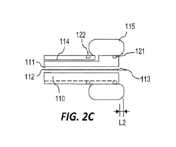
FIGS. 2A-2C show side views of the distal end portion of the multidirectional
balloon
31 tipped catheter system.
4
CA 03168292 2022- 8- 17
WO 2021/167825
PCT/US2021/017528
1
FIG. 2D shows a cross-sectional view of the section A-A' of the distal end
portion of the
2 multidirectional balloon tipped catheter system shown in FIG. IC.
3
FIG. 3 shows an exemplary embodiment of a deflection mechanism that may be
employed
4
to control deflections of the distal end portion of the multidirectional
balloon tipped catheter
system.
6
FIG. 4, shows a workflow diagram for a method for conducting His bundle
sensing and
7 pacing with the multidirectional balloon tipped catheter system.
8 DETAILED DESCRIPTION
9
The following detailed description is merely exemplary in nature and is not
intended to
limit the described embodiments or the application and uses of the described
embodiments. As
11
used herein, the word "exemplary" or "illustrative" means "serving as an
example, instance, or
12
illustration." Any implementation described herein as "exemplary or
"illustrative" is not
13
necessarily to be construed as preferred or advantageous over other
implementations. All of the
14
implementations described below are exemplary implementations provided to
enable persons
skilled in the art to make or use the embodiments of the disclosure and are
not intended to limit
16
the scope of the disclosure, which is defined by the claims. Furthermore,
there is no intention to
17
be bound by any expressed or implied theory presented in the preceding
technical field,
18
background, brief summary or the following detailed description. It is also
to be understood that
19
the specific devices and processes illustrated in the attached drawings, and
described in the
following specification, are simply exemplary embodiments of the inventive
concepts defined in
21
the appended claims. Hence, specific dimensions and other physical
characteristics relating to the
22
embodiments disclosed herein are not to be considered as limiting, unless
the claims expressly
23 state otherwise.
24
With reference to FIGS. 1A-1C shown are an embodiment of multidirectional
balloon
tipped catheter system 100 of the disclosed invention for sensing His bundle
and positioning
26
pacing lead. With reference to FIGS. 2A-2C shown are side views of the
distal end portion of the
27
multidirectional balloon tipped catheter system 100. With reference to FIG.
2D, shown is a cross-
28
sectional view of the section A-A' of the distal end portion of the
multidirectional balloon tipped
29 catheter system 100.
The multidirectional balloon tipped catheter system 100 includes a
multidirectional or
31
deflectable flexible catheter body 110 that includes a proximal end 101 and
a distal end 102. The
5
CA 03168292 2022- 8- 17
WO 2021/167825
PCT/US2021/017528
1 catheter body 110 is French sizes, and includes curls and flexion points
to be multidirectional or
2 deflectable. For example, the catheter body 110 may include a plurality
of flexion points 103, 104
3 to facilitate the multidirectional deflections or bending. The catheter
body 110 has a length
4 sufficient to reach a selected location in a patient's cardiac
structures. The catheter body 110 is
configured to be insertable into a subclavian vein or other vascular access to
approach His bundle.
6 The catheter body 110 includes a plurality of lumens. The plurality of
lumens include at least a
7 wire lumen 111 for cord 112 connected to a pacing lead 113. The wire
lumen 111 includes a wire
8 access port (not shown) accessible to an operator at said catheter
proximal 101 end and a wire exit
9 port 111a at said flexible catheter distal end 102, and a balloon lumen
114 for inflating and
deflating at least one anchor balloon 115. The balloon lumen 114 includes a
balloon control port
11 (not shown) for connecting to balloon control device accessible to an
operator at the catheter
12 proximal end 101 and a balloon port 114a near the multidirectional
catheter distal end 102. The
13 plurality of lumens may further include other lumens such as lumens 125,
126 for wires 123, 124
14 connected to mapping electrodes 121, 122.
The multidirectional balloon tipped catheter system 100 includes compliant or
non-
16 compliant anchor balloon 115 that is mounted on the multidirectional
catheter body 110 near the
17 distal end 102 of the catheter body 110. FIGS. 1A and 2A show deflated
anchor balloon 115, and
18 FIGS. 1B and 2B show inflated anchor balloon 115 at the distal end 102
portion of catheter body
19 110. The anchor balloon 115 is connected to the balloon port 114a of the
catheter lumen 114, and
is in fluid communication through the balloon lumen 114. Fluid, which is
injected or removed at
21 the balloon control port at the proximal end 101, inflates or deflates
the anchor balloon 115 through
22 the balloon lumen 114.
23 The anchor balloon 115 may be inflated with air, saline, contrast and
other solutions, and
24 may be inflated to various sizes. The anchor balloon 115 is placed at a
selected distance from the
distal end 102 of the catheter body 110. For example, when the anchor balloon
115 is deflated, the
26 distance Li of a distal end of the anchor balloon 115 from a distal end
102 of the catheter body
27 110 may be in the range 10 mm (0.4 inches) to 20 mm (0.8 inches). When
the anchor balloon 115
28 is inflated, the anchor balloon 115 may overhang the distal end 102 of
the catheter body 110 by a
29 distance L2 which may be two to three millimeters.
The multidirectional balloon tipped catheter system 100 includes at least one
mapping
31 electrode 121 near the distal end 102 of the catheter body 110. The
mapping electrode 121 allows
6
CA 03168292 2022- 8- 17
WO 2021/167825
PCT/US2021/017528
1 atraumatic mapping of the His bundle potential. The mapping electrode 121
works as a unipolar
2 sensor for detecting and mapping the His bundle potential. In another
embodiment, the catheter
3 system 100 may include second mapping electrode 122 that is placed a few
millimeters behind the
4 first mapping electrode 121 (toward proximal end 101). In this
configuration, mapping electrodes
121, 122 together work as a bipolar sensor for atraumatic mapping of the His
bundle potential,
6 making bipolar sensing possible. The anchor balloon 115 is configured
such that the mapping
7 electrode 121 is exposed at the distal end 102 of the catheter body 110
when the anchor balloon
8 115 is deflated so that mapping the His bundle potential may be performed
by using the electrode
9 121 and/or electrodes 121, 122 to find an appropriate location of the
heart tissue 140 for His bundle
pacing.
11 The catheter body 110 may include wiring lumens 125, 126 that house
electrical wires 123,
12 124 connected to the mapping electrodes 121, 122. The wires 123, 124 at
the proximal end 101 of
13 the catheter body 110 may be coupled to an external device that may send
signals to or receive
14 signals from the mapping electrodes 121, 122.
The multidirectional balloon tipped catheter system 100 includes pacing lead
113 that is
16 connected to cord 112 disposed in the lumen 111. The catheter body 110
includes pacing lead
17 lumen 111 that includes a cord access port (not shown) accessible to an
operating device at the
18 proximal end 101 and exit port 111a at the distal end 102 of the
catheter body 110. The pacing
19 lead lumen 111 may be positioned at a center of the cross-section of the
catheter 110 as shown in
FIG. 2D. The diameter of the pacing lead lumen 111 may be equal to or greater
than 0.91 mm
21 (0.035 inches). The pacing lead 113 may be placed inside the pacing lead
lumen 111 while
22 mapping His bundle potential and positioning the catheter system 100
against heart tissue 140. The
23 pacing lead 113 may advance out of the pacing lead lumen 111 beyond the
distal end 102 of the
24 catheter body 110 to be placed or implanted on the heart tissue 140. The
pacing lead 113 may have
a form of screw helix. FIGS. 1C and 2C show the pacing lead 113 advancing out
of the distal end
26 102 of the catheter body 110.
27 The anchor balloon 115 may be used in an atraumatic fashion over
cardiac structures. The
28 anchor balloon 115 may glide over the cardiac structures, while sensing
is performed by using the
29 mapping electrodes 121, 122 to obtain the best site for lead
implantation. Once an appropriate
location of the heart tissue 140 is determined for His bundle pacing, the
catheter system 100 is
31 used as a conduit for implantation of the pacing lead 113. The anchor
balloon 115 may be inflated
7
CA 03168292 2022- 8- 17
WO 2021/167825
PCT/US2021/017528
1 to anchor the distal end 102 of the catheter body 110 at the appropriate
location of the heart tissue
2 140. When the distal end 102 of the catheter body 110 with the inflated
anchor balloon 115 is
3 positioned and stabilized at the location, the pacing lead 113 may be
advanced to be implanted in
4 the heart tissue 140. Once the pacing lead 113 is in place, the catheter
body 110 may be removed
using multiple methods which may include slitting and splitting the catheter
body, or may be
6 removed by methods that are general practices for lead implantation.
7 With reference now to FIG. 3, shown is an exemplary embodiment of a
mechanical
8 deflection device 130 that can be employed at the proximal end 101
portion of the catheter body
9 110 to control deflections of the distal end portion of the catheter
system 100. Mechanical
deflection mechanism may enable distal end of catheter body 110 to be
deflected or angulated to
11 various angles with respect to a longitudinal axis (from the proximal
end 101 to the distal end 102)
12 of the catheter system 100. Mechanical deflection device 130 may include
a pull wire anchor 131
13 affixed to the catheter body 110 and pull wire actuator 132 connected to
pull wire anchor 131 with
14 pull wire (not shown). Rotation of pull wire actuator 132, as shown, may
exert force on pull wire
anchor 131 that deflects or angulates distal end of the catheter body 110.
Pull wire actuator 132
16 may be rotated by handle connected thereto (not shown). The deflection
device 130 together with
17 the flexion points and curls formed in the catheter body 110 enables the
catheter body 110 to easily
18 navigate over heart structures. . U.S. Patent Application Serial No.
17/061,761 filed on October 2,
19 2020 by the same inventor discloses an improved handle that can be used
for the catheter system
100 of the disclosed invention to provide deflections.
21 With reference to FIG. 4, shown is a workflow diagram for a method
200 for conducting
22 His bundle sensing and pacing with a multidirectional balloon tipped
catheter system 100 including
23 a multidirectional catheter body 110. The catheter system 100 is
inserted into a subclavian vein or
24 vascular access, block 210. The catheter system 100 is guided towards
His bundle, block 211. The
catheter system 100 senses His bundle potential with one or more mapping
electrodes 121, 122
26 disposed at a distal end portion of the catheter body, block 212. The
distal end of the catheter body
27 110 is positioned at a location of the His bundle 140 that is determined
to be appropriate for pacing,
28 block 213. The distal end of the catheter body 110 is anchored at the
appropriate location with
29 inflated anchor balloon 115, block 214. A pacing lead 113 is implanted
into the appropriate
location of the His bundle, block 215. After the pacing lead 113 is implanted,
the catheter body
31 110 with deflated anchor balloon 115 may be removed while leaving the
pacing lead 130 in place.
8
CA 03168292 2022- 8- 17
WO 2021/167825
PCT/US2021/017528
1 The anchor balloon 115 is atraumatic and allows for use of a more
robust catheter designs.
2 The increased rigidity of the catheter body facilitates increased
positional precision and an
3 improved procedural success rate. In an embodiment, the anchor balloon
115 may be a hydrophilic
4 balloon with a surface having hydrophilic nature. The catheter system 100
of the disclosed
invention provides advantages over the conventional devices. Unlike the
conventional devices, the
6 pacing lead 113 of the catheter system 100 of the disclosed invention is
not exposed while the
7 catheter system 100 maps the His bundle potential to find an appropriate
location of heart tissues
8 for His bundle pacing, preventing any issues that can be caused by
exposed screw helix in the
9 conventional devices. The catheter system 100 of the disclosed invention
utilizes atraumatic
anchor balloon that allows maneuvering of the catheter system 100 over cardiac
structures without
11 causing any injuries or damages to heart tissues and also allows to use
more rigid multidirectional
12 catheter body, which increases the ability to adjust to varying
anatomical differences and to
13 accurately maintain position within the beating heart during the implant
procedure.
14 Since many modifications, variations, and changes in detail can be
made to the described
preferred embodiments of the invention, it is intended that all matters in the
foregoing description
16 and shown in the accompanying drawings be interpreted as illustrative
and not in a limiting sense.
17 Consequently, the scope of the invention should be determined by the
appended claims and their
18 legal equivalents.
9
CA 03168292 2022- 8- 17