Note: Descriptions are shown in the official language in which they were submitted.
WO 2014/144107
PCT/US2014/028381
DEVICES, SYSTEMS AND METHODS FOR MONITORING HIP
REPLACEMENTS
CROSS-REFERENCE TO RELATED APPLICATION
[0001] This application claims the benefit under 35 U.S.C. 119(e)
of U.S.
Provisional Patent Application No. 61/789,170 filed March 15, 2013, which
application
is incorporated herein by reference in its entirety.
FIELD OF THE INVENTION
[0002] The present invention relates generally to hip replacements,
and more
specifically, to devices and methods for monitoring the performance of total
and partial
hip replacements.
BACKGROUND
Description of the Related Art
[0003] Hip replacement is one of the most common orthopedic surgical
procedures. It may be carried out when the patient loses sufficient use of the
hip,
typically due to injury, avascular necrosis of the hip, or for the treatment
of extreme
and / or constant joint pain (e.g., due to various types of arthritis (such as
rheumatoid or
osteoarthritis)).
[0004] Hip replacement can take a variety of different forms. In
total hip
replacement (THR), both the femoral head and the acetabulum are replaced. In a
hemi
(partial) hip arthroplasty, only the femoral head is replaced while the
patient's own
acetabulum is retained. The femoral component of a hip replacement may be a
single
piece with the head and stem as an integral, complete unit, or it may be
constructed in
several pieces, such as a femoral stem which is then coupled to a separate
femoral head
piece and neck section (which is often done to provide the patient with custom
fitting
for length and/or femoral head size). The femoral component can be cemented in
place
with a bone cement (cemented hip) or it can be fitted precisely within the
medullary
canal of the femur and held in place without cement (AML - anatomic medullary
locking ¨ stem design). Similarly, the acetabular component of a THR can also
be a
single piece coupled to the hip socket to receives the femoral head, or be a
two-piece
Date Recue/Date Received 2022-07-20
WO 2014/144107
PCT/US2014/028381
component with a shell coupled to the pelvic bone and an inner liner attached
to the
shell. The acetabular component of a THR can be held in place with screws
and/or
cement or it can be affixed without cement.
[0005] Currently, the various components may be made of the same
material
(e.g., all portions can be made of metal), or individual components can be
made from a
variety of different materials. For example, it is common for the acetabular
component
to have a metal shell with an outer surface coating to facilitate bone
attachment and
ingrowth, and an inner lining made from polyethylene, ultrahigh molecular
weight
polyethylene, ceramic, or surgical-grade stainless steel. Similarly, there may
be several
different combinations of materials used in the construction of the femoral
head. For
example, the femoral head can be composed of metal, usually cobalt chromium
(but
also stainless steel or titanium), or a ceramic material, while the femoral
stem is
typically metal (stainless steel, titanium, or cobalt chromium) and often
possesses a
surface coating to encourage incorporation of the implant within the femur.
[0006] Figure 1 shows a total hip joint of a type known in the art.
Figure 2 is an
exploded view of the total hip joint of Figure 1. The acetabular shell may be
made of
any suitable material, preferably a metal or ceramic, and the inner liner may
also be
made of any suitable material that is compatible with the material for the
acetabular
shell. For example, the liner may be made of a polyethylene, an ultrahigh
molecular
weight polyethylene, a ceramic, a metal, or other types of material. The
femoral head
may be made of a metal or a ceramic and can be of the same, or different,
material from
that which composes the acetabular liner; for example, a ceramic femoral head
on a
ceramic acetabular liner (ceramic-on-ceramic hip; COC), a metal femoral head
on a
metal acetabulum (metal-on-metal hip; MOM) or alternatively a metal or ceramic
femoral head on a polyethylene acetabular liner (metal-on-polyurethane, MOP;
metal-
on-cross-linked-polyurethane, MOXP; ceramic-on-polyurethane, COP; ceramic-on-
cross-linked-polyurethane, COXP), or other combinations of the like. The
femoral stem
is usually made of a metal (stainless steel, titanium, cobalt chromium) that
is
biocompatible for long-term use in the patient and is inserted into the shaft
of the femur
and held in place with, or without, bone cement.
[0007] Unfortunately, when a total hip is inserted, various
complications may
arise over time. For example, as shown in Figure 3, there may be wear between
the
2
Date Recue/Date Received 2022-07-20
WO 2014/144107
PCT/US2014/028381
femoral head and the acetabular liner, which leads to improper operation of
the artificial
hip joint. In addition, the patient may experience inflammation and pain if
there is
slight movement or dislocation of any of the components. Depending on the
types of
materials used for the acetabular liner (if present, as in THR) and the
femoral head
(both THR and Hemi-arthroplasty), there may be wear in the acetabular liner
and/or the
femoral head which results in loosening or partial (or full) dislocation of
the joint, may
degrade the performance of the hip, result in difficulty in movement and
ambulation,
and may cause pain and inflammation for the patient. A second common
complication
occurs when, over a period of time (for example 8-12 years), bone loss occurs
in the
tissues surrounding the implant in either the pelvis and/or the femur due to a
process
known as osteolysis.
[0008] Erosion of the bone around the implant may be caused by
material debris
(metal, ceramic, and/or polyurethane fragments) generated by friction between
the
femoral head and acetabular cup entering the tissues surrounding the implant
and
causing inflammation and bone loss. Other potential causes of inflammation and
osteolysis are implant vibration and motion, mechanical wear and tear, lack of
biocompatibility between the implant materials and the surrounding bone, metal
allergy,
and lack of biocompatibility between the bone cement and the surrounding bone.
Additional complications include infection, nerve damage, material
sensitivity, nerve
impingement, and hip dislocation (more likely to occur if the muscle has not
sufficiently healed; usually during the first 4-12 weeks post-surgery).
[0009] Currently, post-operative, in-hospital monitoring of hip
replacement
surgery patients is conducted through personal visits by the hospital staff
and medical
team, physical examination of the patient, medical monitoring (vital signs,
etc.),
evaluation of hip range of motion (ROM), physiotherapy (including early
mobilization
and activity), and diagnostic imaging studies and blood work as required. Once
the
patient is discharged from hospital, prosthesis performance and patient
satisfaction is
checked during periodic doctor's office visits where a thorough history,
physical exam
and supplemental imaging and diagnostic studies are used to monitor patient
progress
and identify the development of any potential complications. During such
visits, the
surgeon typically evaluates the range of motion of the hip, attempts to
identify any pain
3
Date Recue/Date Received 2022-07-20
WO 2014/144107
PCT/US2014/028381
that occurs during certain motions or actions, and questions the patient to
determine
activity levels, daily functioning, pain control, and rehabilitation progress.
[0010] Unfortunately, most of the patient's recuperative period
occurs between
hospital or office visits. It can, therefore, be very difficult to accurately
measure and
follow full joint range of motion (ROM can change depending on pain control,
degree
of anti-inflammatory medication, time of day, recent activities, and/or how
the patient is
feeling at the time of the examination), "real life" prosthesis performance,
patient
activity levels, exercise tolerance, and the effectiveness of rehabilitation
efforts
(physiotherapy, medications, etc.) from the day of surgery through to full
recovery. For
much of this information, the physician is dependent upon patient self-
reporting or third
party observation to obtain insight into post-operative treatment
effectiveness and
recovery and rehabilitation progress; in many cases this is further
complicated by a
patient who is uncertain what to look for, has no knowledge of what
"normal/expected"
post-operative recovery should be, is non-compliant, or is unable to
effectively
communicate their symptoms. Furthermore, identifying and tracking
complications (in
and out of hospital) prior to them becoming symptomatic, arising between
doctor visits,
or those whose presence is difficult to detect would also provide beneficial,
additional
information to the management of THR patients. Currently, in all instances,
neither the
physician nor the patient has access to the type of "real time," continuous,
objective,
prosthesis performance measurements that they might otherwise like to have.
[0011] The present invention discloses novel total and partial hip
replacements
which overcome many of the difficulties of previous hip prostheses, methods
for
constructing and monitoring these novel hip replacements, and further provides
other
related advantages.
SUMMARY
[0012] Briefly stated, full and partial hip prostheses are provided
with a number
of sensors to monitor the integrity and efficaciousness of the artificial hip
joint within
the patient. The sensors may be positioned on the outer surface of the
prosthetic hip, on
the inner surfaces of the prosthetic hip, within the prosthetic material
(stainless steel,
titanium, cobalt chromium, polyurethane, high molecular weight polyurethane,
ceramics, etc.) itself, between the various components that comprise the
prosthetic hip,
4
Date Recue/Date Received 2022-07-20
WO 2014/144107
PCT/US2014/028381
within the bone cement (e.g., PMMA, or PMMA and MMA copolymer blends) used to
secure the hip (if present), and/or within the tissues surrounding the
prosthesis. Within
certain embodiments, the sensors are of the type that are passive and thus do
not require
their own power supply.
[0013] Within one aspect of the invention assemblies are provided for
positioning and placement within a patient an implant comprising a total or
partial hip
prosthesis; and a sensor positioned on, in, or around the prosthesis. Within
various
embodiments the sensor can be positioned on an outer surface of the prosthetic
hip, on
an inner surface of the prosthetic hip, within the materials used to construct
the
prosthetic hip, between the various components that make up the prosthetic
hip, on or in
the bone cement used to secure the prosthetic hip, on or in the tissues
surrounding the
prosthetic hip (typically bone or bone marrow, but also muscle, ligament,
tendon, joint
capsule and/or synovial compartment), or any combination of these.
Representative
examples of sensors suitable for use within the present invention include
accelerometers
(acceleration, tilt, vibration, shock and rotation sensors), pressure sensors,
contact
sensors, position sensors, chemical microsensors, tissue metabolic sensors,
mechanical
stress sensors and temperature sensors. Within particularly preferred
embodiments the
sensor is a wireless sensor, or a sensor connected to a wireless
microprocessor.
[0014] Within further embodiments a plurality of the aforementioned
sensors
are positioned on, within, or around (bone cement or tissue) the prosthetic
hip, and
within preferred embodiments, the prosthetic hip can contain more than one
type of
sensor (e.g., one or more of, or any combination of the following:
acceleration sensors,
tilt sensors, vibration sensors, shock sensors, rotation sensors, pressure
sensors, contact
sensors, position sensors, chemical microsensors, tissue metabolic sensors,
and
mechanical stress sensors).
[0015] According to various embodiments, sensors are placed at
different
locations in a replacement hip joint in order to monitor the operation,
movement,
function, wear, performance, potential side effects and medical status of the
artificial
hip and its interface with the live tissue of the patient. Live, continuous,
in situ,
monitoring of patient activity, patient function, prosthesis activity,
prosthesis function,
prosthesis performance, and potential side effects is provided. In addition,
information
is available on many aspects of the hip replacement prosthesis and its
interaction with
Date Recue/Date Received 2022-07-20
WO 2014/144107
PCT/US2014/028381
the patient's own body tissues, including clinically important measurements
not
currently available through physical examination, medical imaging and
diagnostic
medical studies.
[0016] According to one embodiment the sensors provide evaluation
data on the
range of motion (ROM) of the hip. Currently, ROM is usually measured
clinically by
the physician passively moving the hip joint through a full range of motion
during
physical examination and recording the results (degrees of flexion, extension,
abduction, adduction, external rotation, internal rotation and rotation in
flexion).
Motion sensors and accelerometers can be used to accurately determine the full
ROM
of the prosthetic hip joint both during physical examination and during
nolinal daily
activities between visits.
[0017] According to one embodiment, contact sensors are provided
between the
prosthesis and the surrounding bone, between the prosthesis and the
surrounding bone
cement, and/or between the bone cement and the surrounding bone in order to
measure
bone erosion and loosening around the implant. In other embodiments, strain
gauges
are provided to detect the strain between the prosthesis and the surrounding
bone,
between the prosthesis and the surrounding bone cement, between the bone
cement and
the surrounding bone, and also the strain which is exerted on the various
portions of the
prosthesis. Sudden increases in strain may indicate that too much stress is
being placed
on the replacement prosthesis, which may increase damage to the body. For
example, a
gradual, long-term decrease in strain may cause bone reabsorption around the
implant,
leading to loosening of the prosthesis or fractures in the bone surrounding
the
prosthesis.
[0018] According to other embodiments, accelerometers are provided
which
detect vibration, shock, tilt and rotation. According to other embodiments,
sensors for
measuring surface wear, such as contact or pressure sensors, may be embedded
at
different depths within the femoral head, the acetabulum, and/or the
acetabular cup in
order to monitor articular surface erosion. In other embodiments, position
sensors, as
well as other types of sensors, are provided which indicate the range of
motion and
monitor for partial (or complete) hip dislocation in actual use over a period
of time.
[0019] Within further embodiments, the artificial hip (total or
partial) can
contain sensors at specified densities in specific locations. For example, the
artificial
6
Date Recue/Date Received 2022-07-20
WO 2014/144107
PCT/US2014/028381
hip can have a density of sensors of greater than one, two, three, four, five,
six, seven,
eight, nine, or ten sensors (e.g., acceleration sensors, tilt sensors,
vibration sensors,
shock sensors, rotation sensors, pressure sensors, contact sensors, position
sensors,
chemical microsensors, tissue metabolic sensors, and mechanical stress
sensors, or any
combination of these) per square centimeter of the device. Within other
embodiments,
the artificial hip (total or partial) can have a density of sensors of greater
than one, two,
three, four, five, six, seven, eight, nine, or ten sensors (e.g., acceleration
sensors, tilt
sensors, vibration sensors, shock sensors, rotation sensors, pressure sensors,
contact
sensors, position sensors, chemical microsensors, tissue metabolic sensors,
and
mechanical stress sensors, or any combination of these) per cubic centimeter
of the
device. Within related embodiments, the sensors (e.g., acceleration sensors,
tilt sensors,
vibration sensors, shock sensors, rotation sensors, pressure sensors, contact
sensors,
position sensors, chemical microsensors, tissue metabolic sensors, and
mechanical
stress sensors) can be positioned at particular locations on, within, or
around the
artificial hip, including for example, the femoral stem, the femoral neck, the
femoral
head, the acetabular cup, the acetabular lining, within portions of the device
which are
to be connected (e.g., the connecting segments of the femoral stem, femoral
neck and
femoral head; the connecting segments of the acetabular cup and the acetabular
lining),
and around the artificial hip (on or in the bone cement used to secure the
prosthetic hip,
on or in the tissues surrounding the prosthetic hip - typically bone or bone
marrow, but
also muscle, ligament, tendon, joint capsule and/or synovial compartment).
[0020] Within certain embodiments of the invention, the total or
partial hip
prosthesis is provided with a specific unique identifying number, and within
further
embodiments, each of the sensors on, in or around the prosthetic hip each have
either a
specific unique identification number, or a group identification number (e.g.,
an
identification number that identifies the sensor as an acceleration sensor, a
tilt sensor, a
vibration sensor, a shock sensor, a rotation sensor, a pressure sensor, a
contact sensor, a
position sensor, a chemical microsensor, a tissue metabolic sensor, or a
mechanical
stress sensor). Within yet further embodiments, the specific unique
identification
number or group identification number is specifically associated with a
position on, in
or around the prosthetic hip.
7
Date Recue/Date Received 2022-07-20
WO 2014/144107
PCT/US2014/028381
[0021] Within other aspects of the invention methods are provided for
monitoring an implanted total or partial hip prosthesis comprising the steps
of
transmitting a wireless electrical signal from a location outside the body to
a location
inside the body; receiving the signal at a sensor positioned on, in or around
an artificial
hip located inside the body; powering the sensor using the received signal;
sensing data
at the sensor; and outputting the sensed data from the sensor to a receiving
unit located
outside of the body.
[0022] The integrity of the partial or total hip prosthesis can be
wirelessly
interrogated and the results reported on a regular basis. This permits the
health of the
patient to be checked on a regular basis or at any time as desired by the
patient and/or
physician.
[0023] Within further embodiments, each of the sensors contains a
signal-
receiving circuit and a signal output circuit. The signal-receiving circuit
receives an
interrogation signal that includes both power and data collection request
components.
Using the power from the interrogation signal, the sensor powers up the parts
of the
circuitry needed to conduct the sensing, carries out the sensing, and then
outputs the
data to the interrogation module. The interrogation module acts under control
of a
control unit which contains the appropriate I/O circuitry, memory, a
controller in the
form of a microprocessor, and other circuitry in order to drive the
interrogation module.
Within yet other embodiments the sensor (e.g., an acceleration sensor, a tilt
sensor, a
vibration sensor, a shock sensor, a rotation sensor, a pressure sensor, a
contact sensor, a
position sensor, a chemical microsensor, a tissue metabolic sensor, or a
mechanical
stress sensor) are constructed such that they may readily be incorporated into
or
otherwise mechanically attached to the hip prosthesis (e.g., by way of a an
opening or
other appendage that provides permanent attachment of the sensor to the hip
prosthesis)
and/or readily incorporated into the bone cement or the tissues that surround
the hip
prosthesis.
[0024] Within yet other aspects of the invention methods devices are
provided
suitable for transmitting a wireless electrical signal from a location outside
the body to a
location inside the body; receiving the signal at one of the aforementioned
sensors
positioned on, in or around a prosthetic hip located inside the body; powering
the sensor
using the received signal; sensing data at the sensor; and outputting the
sensed data
8
Date Recue/Date Received 2022-07-20
WO 2014/144107
PCT/US2014/028381
from the sensor to a receiving unit located outside of the body. Within
certain
embodiments the receiving unit can provide an analysis of the signal provided
by the
sensor.
[0025] The data collected by the sensors can be stored in a memory
located
within the femoral stem. During a visit to the physician, the data can be
downloaded
via a wireless sensor, and the doctor is able to obtain data representative of
real-time
performance of the prosthesis.
[0026] The advantages obtained include more accurate monitoring of
the
prosthesis and permitting medical reporting of accurate, in situ data that
will contribute
to the health of the patient. The details of one or more embodiments are set
forth in the
description below. Other features, objects and advantages will be apparent
from the
description, the drawings, and the claims. In addition, the disclosures of all
patents and
patent applications referenced herein are incorporated by reference in their
entirety.
BRIEF DESCRIPTION OF THE DRAWINGS
[0027] Figure 1 is an isometric view of a total hip replacement.
[0028] Figure 2 is an exploded view of the total hip replacement of
Figure 1.
[0029] Figure 3 shows the total hip replacement within the pelvis of
a patient.
[0030] Figure 4 is an exploded view of a total hip having sensors
thereon
according to various embodiments as described herein.
[0031] Figure 5 illustrates the embodiment of Figure 4 after the hip
has been
replaced showing contact locations with the bones of the patient.
[0032] Figure 6A is an exploded view of the acetabular cup, a liner,
and the
femoral having various sensors thereon according to the various embodiments
described
herein. Figure 6B is an illustration of the incorporation of strain gauges in
a variety of
locations.
[0033] Figure 7A is a side view of the femoral implant with the ball
attached.
[0034] Figure 7B is an enlarged side view of the femoral implant with
various
sensors and a power generation segment.
[0035] Figure 8A is a top side view of an acetabular cup having
various sensors
according to the embodiments described herein.
9
Date Recue/Date Received 2022-07-20
WO 2014/144107
PCT/US2014/028381
[0036] Figure 8B is a liner in the acetabular cup of Figure 9 having
various
sensors therein.
[0037] Figure 9 is a side view of a total assembled hip with examples
of
different sensor locations.
[0038] Figure 10 shows the completed hip assembly of Figure 9 fully
functional
in a patient, with the various different types of sensors.
[0039] Figures 11A and 11B illustrate different types of hip movement
which
may be measured and monitored according to various embodiments as disclosed
herein.
[0040] Figure 12 illustrates an information and communication
technology
system embodiment arranged to process sensor data.
[0041] Figure 13 is a block diagram of a sensor, interrogation
module, and a
control unit according to one embodiment of the invention.
[0042] Figure 14 is a schematic illustration of one or more sensors
positioned on
a hip replacement within a subject which is being probed for data and
outputting data,
according to one embodiment of the invention.
DETAILED DESCRIPTION OF THE INVENTION
[0043] Briefly stated the present invention provides a variety of hip
replacements that can be utilized to monitor the integrity and efficaciousness
of the
device. Prior to setting forth the invention however, it may be helpful to an
understanding thereof to first set forth definitions of certain terms that are
used
hereinafter.
[0044] "Hip replacement" as that teim is utilized herein, may take a
variety of
different forms and may involve replacement of all or portions of the
patient's hip joint
with synthetic materials. In total hip replacement (THR), both the femoral
head and the
acetabulum are replaced. In a hemi (partial) hip arthroplasty, only the
femoral head is
replaced while the patient's own acetabulum is retained. The femoral component
of a
hip replacement may be a single piece with the head and stem as an integral,
complete
unit, or it may be constructed in several pieces, such as a femoral stem which
is then
coupled to a separate femoral head piece and neck section (which is often done
to
provide the patient with custom fitting for length and/or femoral head size).
The
femoral component can be cemented in place with PMMA bone cement (cemented
hip)
Date Recue/Date Received 2022-07-20
WO 2014/144107
PCT/US2014/028381
or it can be fitted precisely within the medullary canal of the femur and held
in place
without cement (AML - anatomic medullary locking ¨ stem design). Similarly,
the
acetabular component of a THR can also be a single piece coupled to the hip
socket to
receives the femoral head, or be a two-piece component with a shell coupled to
the
pelvic bone and an inner liner attached to the shell. The acetabular component
of a
THR can be held in place with screws and/or cement or it can be affixed
without
cement.
[0045] Currently, the various components may be made of the same
material,
for example, all portions can be made of metal, or individual components can
be made
from a variety of different materials. For example, it is common for the
acetabular
component to have a metal shell with an outer surface coating to facilitate
bone
attachment and ingrowth, and an inner lining made from polyethylene, ultrahigh
molecular weight polyethylene, ceramic, or surgical-grade stainless steel.
Similarly,
there may be several different combinations of materials used in the
construction of the
femoral head. For example, the femoral head can be composed of metal, usually
cobalt
chromium (but also stainless steel or titanium), or a ceramic material, while
the femoral
stem is typically metal (stainless steel, titanium, or cobalt chromium) and
often
possesses a surface coating to encourage incorporation of the implant within
the femur.
[0046] As utilized herein the terms "hip implant" or "hip
replacement" or "hip
replacement or portion thereof' or "medical device" should be understood,
unless the
specific context requires otherwise, to refer to any or all of the various
components that
go into making a total hip prosthesis, including for example, the femoral
stem, femoral
head, and acetabular assembly, as well as their various sub-components. "Hip
replacement prosthesis" should be understood to refer to either a partial or
total hip
replacement prosthesis.
[0047] "Sensor" refers to a device that can be utilized to measure
one or more
different aspects of a body, of a hip implant inserted within a body, and/or
the integrity,
impact, efficaciousness or effect of the hip implant inserted within a body.
Representative examples of sensors suitable for use within the present
invention
include, for example, fluid pressure sensors, contact sensors, position
sensors, pulse
pressure sensors, blood volume sensors, blood flow sensors, chemistry sensors
(e.g., for
blood and/or other fluids), metabolic sensors (e.g., for blood and/or other
fluids),
11
Date Recue/Date Received 2022-07-20
WO 2014/144107
PCT/US2014/028381
accelerometers, mechanical stress sensors and temperature sensors. Within
certain
embodiments the sensor can be a wireless sensor, or, within other embodiments,
a
sensor connected to a wireless microprocessor. Within further embodiments one
or
more (including all) of the sensors can have a Unique Sensor Identification
number
("USI") which specifically identifies the sensor.
[0048] A wide variety of sensors (also referred to as
Microelectromechanical
Systems or "MEMS", or Nanoelectromechanical Systems or "NEMS", and BioMEMS
or BioNEMS, see generally https://en..wikipedia.orgiwiki/MEMS) can be utilized
within
the present invention. Representative patents and patent applications include
U.S.
Patent No. 7,383,071 and U.S. Publication No. 2010/0285082. Representative
publications include "Introduction to BioMEMS" by Albert Foch, CRC Press,
2013;
"From MEMS to Bio-MEMS and Bio-NEMS: Manufacturing Techniques and
Applications by Marc J. Madou, CRC Press 2011; "Bio-MEMS: Science and
Engineering Perspectives, by Simona Badilescu, CRC Press 2011; "Fundamentals
of
BioMEMS and Medical Microdevices" by Steven S. Saliterman, SPIE-The
International Society of Optical Engineering, 2006; "Bio-MEMS: Technologies
and
Applications", edited by Wanjun Wang and Steven A. Soper, CRC Press, 2012; and
"Inertial MEMS: Principles and Practice" by Volker Kempe, Cambridge University
Press, 2011; Polla, D. L., et al., "Microdevices in Medicine," Ann. Rev.
Biomed. Eng.
2000, 02:551-576; Yun, K. S., et al., "A Surface-Tension Driven Micropump for
Low-
voltage and Low-Power Operations," J. Microelectromechanical Sys., 11:5,
October
2002, 454-461; Yeh, R., et al., "Single Mask, Large Force, and Large
Displacement
Electrostatic Linear Inchworm Motors," J. Microelectromechanical Sys., 11:4,
August
2002, 330-336; and Loh, N. C., et al., "Sub-10 cm3Interferometric
Accelerometer with
Nano-g Resolution," J. Microelectromechanical Sys., 11:3, June 2002, 182-187;
all of
the above of which are incorporated by reference in their entirety.
[0049] In order to further understand the various aspects of the invention
provided
herein, the following sections are provided below: A. Medical Uses of Hip
Implants; B.
Representative Embodiments of Hip Implants; C. Coatings on Hip Implants; D.
Drug-
Eluting Hip Implants; E. Methods for Monitoring Infections in Hip Implants; F.
Generation of Power; G. Medical Use of Sensors; H. Medical Imaging and Self-
Diagnosis of Assemblies Comprising Hip Implants, Predictive Analysis and
Predictive
12
Date Recue/Date Received 2022-07-20
WO 2014/144107
PCT/US2014/028381
Maintenance; I. Methods of Monitoring Assemblies Comprising Hip Implants; and
J.
Collection, Transmission, Analysis, and Distribution of Data from Assemblies
Comprising Hip Implants.
A. MEDICAL USES OF HIP REPLACEMENTS
[0050] Hip replacement is carried out when the patient loses
sufficient use of
the hip so as to result in disability, loss of movement and function, impaired
ambulation, and/or continuous joint pain and discomfort. Common causes of
impaired
hip function leading to total or partial hip replacement include trauma
(typically a hip
fracture; often at the femoral neck), avascular necrosis of the hip, or
various types of
arthritis (such as rheumatoid arthritis or osteoarthritis). In most patients,
the operation
is successful in improving ambulation, restoring function and reducing pain;
as a result,
it is one of the most common orthopedic procedures in the Western World.
B. REPRESENTATIVE EMBODIMENTS OF HIP IMPLANTS
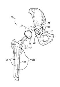
[0051] Figure 4 illustrates a prosthesis 10 in the form of a
replacement hip
having one or more sensors 22 as described herein. The replacement hip
includes an
acetabular shell 12 in which an acetabular liner 14 is placed. It also
includes a femoral
assembly 16 which includes two components, a femoral head 18 and a femoral
implant
or femoral stem 20 (also having a femoral neck 17).
[0052] Figure 5 shows the hip replacement prosthesis 10 as positioned
in a
patient, in an exploded view. As shown in Figure 5, the acetabular shell 12 is
fixed to
the pelvis bone 23. The femoral stem 20 is coupled to the femur 24 and the
femoral
head 18 is shown ready for positioning on the femoral stem 20 and also for
entering the
liner 14 of the acetabular shell. Figures 4 and 5 will be described jointly in
order to
illustrate various embodiments.
[0053] A plurality of sensors 22 are positioned in the prosthesis 10
in order to
monitor, in situ, the real-time operation of the patient activity and the
prosthesis
performance. A variety of these sensors will now be described according to
various
embodiments.
[0054] In one embodiment, contact sensors 22 are provided on the
outer surface
of the acetabular shell 12. These sensors 22 detect and record contact between
adjacent
13
Date Recue/Date Received 2022-07-20
WO 2014/144107
PCT/US2014/028381
parts, such as the between the acetabular shell 12 and the pelvis 23 and/or
between the
acetabular shell and the bone cement (if present) and/or between the bone
cement (if
present) and the pelvis. The contact sensors 22 can detect loosening of the
prosthesis
and its connection to the surrounding cement (if present) and/or pelvic bone.
Loosening of the acetabulum is a common complication that occurs (typically
over 8-12
years) when bone loss takes place in the pelvic bones surrounding the
acetabulum (e.g.,
due to a process known as osteolysis). Erosion of the bone around the implant
may be
caused by material debris (metal, ceramic, and/or polyurethane fragments)
generated by
friction between the femoral head and acetabular cup entering the pelvic
tissues
surrounding the acetabulum and causing inflammation and bone loss. Other
potential
causes of inflammation and osteolysis are implant vibration and motion,
mechanical
wear and tear, lack of biocompatibility between the implant materials and the
surrounding bone, metal allergy, and lack of biocompatibility between the bone
cement
and the surrounding bone. In addition, the contact sensors 22 may indicate
that the
acetabular shell 12 is positioned further from the pelvic bone 23 than desired
as a result
of material debris being built up over time and/or the presence of
inflammation between
the shell and the pelvic bone. A plurality of contact sensors 22 are
positioned at
different locations around the acetabular shell 12. In the example shown, a
number of
sensors are shown positioned on the outer surface of the acetabular shell 12.
In various
embodiments, these sensors may be positioned in a variety of different
patterns based
on the contact locations to the pelvis bone and/or the surrounding bone cement
(if
present). For example, they may be arranged in the pattern of an X, as oval or
concentric rings around the acetabular shell from the outermost circumference
to the
crown or in various other patterns, in order to collect accurate data on the
physical
contact between the acetabular shell 12 and the pelvic bone 23 and/or
surrounding bone
cement (if present). Contact sensors can also be dispersed within/arranged
within the
bone cement (if present) so as to collect data on the physical contact between
the bone
cement and the acetabular prosthesis and/or between the bone cement and the
pelvic
bone. Within various embodiments,
[0055] Contact sensors 22 may also be positioned at various locations
on the
two surfaces of the acetabular liner 14. The contact sensors 22 can therefore
sense the
contact (and/or movement) between the acetabular liner and the acetabular
shell (these
14
Date Recue/Date Received 2022-07-20
WO 2014/144107
PCT/US2014/028381
sensors could be "paired" so as to detect shifting between the acetabular
liner and
shell), as well as contact between the femoral head and the acetabular liner.
Similarly
contact sensors 22 can be positioned at various locations on the femoral head
to detect
contact between the femoral head and the acetabular liner. Thus, in the
embodiment of
Figures 4 and 5, a variety of contact sensors are provided in order to monitor
contact
between the bone and the acetabular component, and between the femoral head
and the
acetabular liner. Dislocation of the femoral head from the natural or
synthetic
acetabulum of a prosthetic hip is a common complication of hip replacement
occurring
shortly after surgery (particularly while the surrounding supportive tissues
are healing
from surgery); sensors on the femoral head and/or acetabulum can alert the
patient and
the healthcare provider if joint dislocation has occurred. Partial or
incomplete
dislocation (subluxation) of the hip joint can also occur and may not be
readily evident
to the patient or the physician; contact sensors on the femoral head and/or
acetabulum
can determine of the joint is functioning (tracking) correctly and if
subluxation (even if
subclinical or asymptomatic) is occurring.
[0056] Additional contact sensors can be positioned on the femoral
stem as
well, to monitor contact between the femoral stem and the femur and/or contact
between the femoral stem and the surrounding bone cement (if present). Contact
sensors can also be dispersed within/arranged within the bone cement (e.g.,
22B. if
present) so as to collect data on the physical contact between the bone cement
and the
femoral prosthesis and/or between the bone cement and the femoral canal. These
sensors 22 and 22B can detect and record contact between connecting parts in a
modular femoral prosthesis, such as the between the femoral head 18, femoral
neck 17
and / or the femoral stem 20. These sensors, which can be arranged in
corresponding
pairs on adjacent pieces, can be used to insure that the connecting elements
of a
modular femoral prosthesis are properly aligned and fitted. Sensors on the
femoral
shaft 20 can be used to monitor the contact between the femoral shaft and the
femur
and/or the contact between femoral shaft and the surrounding bone cement (if
present);
sensors in the bone cement can be used to monitor the contact between the bone
cement
(e.g., 22B, if present) and the femur. The contact sensors on the femoral
shaft 22 can
detect loosening of the prosthesis and its connection to the surrounding
cement (if
present) and/or the femur. Loosening of the femoral shaft is a common
complication
Date Recue/Date Received 2022-07-20
WO 2014/144107
PCT/US2014/028381
that occurs when (typically over 8-12 years), bone loss occurs in the femoral
canal
surrounding the femoral shaft due to osteolysis. As described above, erosion
of the
bone around the implant may be caused by material debris (metal, ceramic,
and/or
polyurethane fragments) generated by friction between the femoral head and
acetabular
cup entering the femoral tissues surrounding the femoral prosthesis and
causing
inflammation and bone loss. Other potential causes of inflammation and
osteolysis are
implant vibration and motion, mechanical wear and tear, lack of
biocompatibility
between the implant materials and the surrounding bone, metal allergy, and
lack of
biocompatibility between the bone cement and the surrounding bone. A plurality
of
contact sensors 22 are positioned at different locations around the femoral
shaft. As
shown in Figures 4 and 5, sensors are shown positioned on the outer surface of
the
femoral shaft. In various embodiments, these sensors may be positioned in a
variety of
different patterns based on the contact locations to the femoral canal and/or
the
surrounding bone cement (if present). For example, they may be arranged in the
pattern
of a helix, as vertical lines or concentric rings around the femoral shaft or
in various
other patterns, in order to collect accurate data on the physical contact
between the
femoral shaft 20 and the femur and/or surrounding bone cement (if present).
Within
various embodiments of the invention contact sensors are placed on the femoral
shaft,
and the femur and /or bone cement at a density of greater than one, two,
three, four,
five, six, seven, eight, nine, or ten sensors per square centimeter, or, per
cubic
centimeter of the device.
[0057] Figure 6A illustrates an exploded version of the acetabular
shell 12, the
liner 14, and the femoral head 18 to permit clear illustration of various
positions for
strain gauges 26 that can be positioned on the prosthesis. The contact sensors
22 are
not shown in Figure 6, but could be used concurrently with the strain gauges
and be
positioned adjacent to each other or be the same sensor. Strain gauges 26 may
be
positioned at various locations on the acetabular shell 12 to detect strain
encountered
between the prosthesis and the surrounding bone. A decrease in strain may
indicate that
there is bone resorbtion (loss), which could lead to loosening of the
prosthesis, or
fractures. The strain sensors 26 provide a different data point than the
contact sensors
22. The contact sensors 22 merely specify whether there is current contact
between
adjacent structures and thus provide a good indication of whether there is
abutting
16
Date Recue/Date Received 2022-07-20
WO 2014/144107
PCT/US2014/028381
contact between two surfaces. However, they do not provide an indication of
the strain
that is present in either of the surfaces, on the other hand, the strain
sensors 26 output
data indicative of the mechanical strain forces being applied across the
implant which,
if not corrected, can be a harbinger of future loosening and prosthesis
failure. In
addition, the strain gauges 26 may be of the type which indicates the strain
which is
being exhibited between two surfaces, such as between the acetabular liner and
the
pelvic bone or between the acetabular shell 12 and the acetabular liner 14.
Further,
such strain gauges may collect data regarding the strain and location of such
strain
between the femoral head 18 and the acetabular liner 14.
[0058] As shown in Figure 6B, strain gauges can be located on the
femoral
prosthesis; particularly the femoral stem, but also the femoral neck and the
femoral
head. Strain gauges may be positioned at various locations on the femoral stem
to
detect strain encountered between the prosthesis and the surrounding bone. A
decrease
in strain may indicate that there is bone resorbtion (loss) in the femoral
canal, which
could lead to loosening of the prosthesis, or femoral fractures. The strain
sensors can
provide an indication of the strain that is present in the femoral shaft and
measure the
most important mechanical strain forces being applied across the implant
which, if not
corrected, have a high probability of resulting in loosening and prosthesis
failure.
Within various embodiments of the invention strain sensors are placed on the
acetabular
shell, acetabular liner, femoral shaft, and the femur and /or bone cement at a
density of
greater than one, two, three, four, five, six, seven, eight, nine, or ten
sensors per square
centimeter, or, per cubic centimeter of the device.
[0059] Figures 7A and 7B illustrate one embodiment in which
accelerometers
are positioned at various locations in and on the femoral shaft 18, femoral
neck and
femoral head. In particular, as shown in Figure 7A one or more accelerometers
may be
positioned on the femoral head 16. In addition, one or more acceleration
sensors 42 in
the form of accelerometers or gyroscopes can be positioned on the surface of
or inside
the femoral shaft portion 18. Accelerometers provide the benefit of being able
to detect
acceleration, vibration, shock, tilt, and rotation of various components. They
permit the
ability to measure performance of the prosthesis 10 under various conditions
and over
long periods of time. In this particular example, the prosthesis 10 is a hip
replacement
joint. Of course, it could be any other prosthesis, such as a prosthetic elbow
joint,
17
Date Recue/Date Received 2022-07-20
WO 2014/144107
PCT/US2014/028381
shoulder joint, metacarpal joint, ankle joint, or the like. Within various
embodiments of
the invention strain sensors are placed on the acetabular shell, acetabular
liner, femoral
shaft, and the femur and /or bone cement at a density of greater than one,
two, three,
four, five, six, seven, eight, nine, or ten sensors per square centimeter, or,
per cubic
centimeter of the device.
[0060] Shortly after the hip has been replaced, the leg will be
mobilized, at first
passively, then actively; shortly thereafter, the patient will begin gradual
weight bearing
on the joint. The accelerometers 42 will measure the movement of the hip
socket
during movement, including during ambulation as the leg swings forward, hits
the
ground, plants, is lifted off the ground, and the body is propelled forward.
In addition,
the accelerometers will measure the impact of the foot hitting the ground and
the effect
of the force being transferred through the femur to the pelvic bones and any
vibration,
shock or rotation which may occur at different locations in the prosthesis 10.
As the
patient continues to improve their range of motion postoperatively, the
acceleration
experienced at different locations in the prosthetic hip joint, can be
monitored. It will
be expected that as the patient heals from the surgery, activity levels will
progressively
increase, ambulation will improve, steps will be more rapid (and fluid) and,
in addition,
greater stride length will be achieved with each step. This may result in
greater impact
every time the foot hits the ground, which can be measured over time (and
compared to
previous values) by the various accelerometers 42 positioned on the femoral
head 16, in
the femoral stem 18 and in other locations on the prosthesis 10. Postoperative
progress
can be monitored (readings compared from day-to-day, week-to-week, etc.) and
the
information compiled and relayed to both the patient and the attending
physician
allowing rehabilitation to be followed sequentially and compared to expected
(typical
population) nouns. Within certain embodiments, a wearable device interrogates
the
sensors on a selected or randomized basis, and captures and /or stores the
collected
sensor data. This data may then be downloaded to another system or device (as
described in further detail below).
[0061] Integrating the data collected by the sensors described herein
(e.g.,
contact sensors, strain gauges and/or accelerometers) with simple, widely
available,
commercial analytical technologies such as pedometers and global positioning
satellite
(GPS) capability, allows further clinically important data to be collected
such as, but
18
Date Recue/Date Received 2022-07-20
WO 2014/144107
PCT/US2014/028381
not restricted to: extent of patient ambulation (time, distance, steps, speed,
cadence),
patient activity levels (frequency of activity, duration, intensity), exercise
tolerance
(work, calories, power, training effect), range of motion (discussed later)
and prosthesis
perfolmance under various "real world" conditions. It is difficult to
overstate the value
of this information in enabling better management of the patient's recovery.
An
attending physician (or physiotherapist, rehabilitation specialist) only
observes the
patient episodically during scheduled visits; the degree of patient function
at the exact
moment of examination can be impacted by a multitude of disparate factors such
as: the
presence or absence of pain, the presence or absence of inflammation,
stiffness, time of
day, compliance and timing of medication use (pain medications, anti-
inflammatories),
recent activity and exercise levels, patient strength, mental status, language
barriers, the
nature of their doctor-patient relationship, or even the patient's ability to
accurately
articulate their symptoms ¨ to name just a few. Continuous monitoring and data
collection can allow the patient and the physician to monitor progress
objectively by
supplying information about patient function under numerous conditions and
circumstances, to evaluate how performance has been affected by various
interventions
(pain control, exercise, physiotherapy, anti-inflammatory medication, rest,
etc.), and to
compare rehabilitation progress versus previous function and future expected
function.
Better therapeutic decisions and better patient compliance can be expected
when both
the doctor and the patient have the benefit of observing the impact of various
treatment
modalities on patient rehabilitation, activity, function and overall
performance.
[0062] The sensor used for the contact, strain and accelerometers can
be an
acceptable type of those generally available (see e.g., U.S. Patents
7,450,332;
7,463,997 and 7,924,267 which describe various types of such sensors,
including
MEMs sensors that can act as strain gauges, accelerometers and many other
sensing
functions). The particular sensor described in U.S. patent 7,450,332, which
detects free
fall of an object and motion of an object with respect to a gravity field,
would have
particular benefits in being able to detect and store all the forces acting on
the leg and
the full motion of the leg, during passive and active motion and when it is
swinging in
between steps, both before, after and during impact with the ground.
[0063] Figures 7A, 8A and 8B illustrate yet another type of sensor,
articular
surface wear sensors 46 that may be positioned at various locations in the
acetabular
19
Date Recue/Date Received 2022-07-20
WO 2014/144107
PCT/US2014/028381
liner and the femoral head. According to one embodiment, one or more articular
surface wear sensors are positioned at various depths of the acetabular liner
14 as
shown in Figures 7A and 8B and/or the femoral head 16. These sensors 46 for
measuring the surface wear may be contact pressure sensors that are embedded
within
the acetabular liner and/or femoral head at varying depths in order to monitor
articular
surface erosion (and provide data as to the extent and depth of surface wear
of the two
components). They may also be positioned between the acetabular shell 12 and
the
acetabular liner 14 as shown in Figures 8A and 8B in order to monitor any kind
of wear
or degradation of the physical contact between the shell 12 and the liner 14.
[0064] Figure 9 shows an example of the complete prosthesis in the
form of a
hip replacement prosthesis having a plurality of different sensors (e.g., 22,
24, 42, 44,
and 46) thereon. It may include, in a single prosthesis hip 10, a plurality of
contact
sensors 22, strain gauges 24, accelerometers 42, articular wear surface
sensors 46, as
well as electric power generation structure 44. In addition, a plurality of
position
sensors can also be placed to monitor, record and transfer the exact position
of the head
18 relative to the acetabular liner 14.
[0065] Figure 10 illustrates different locations at which position
sensors 52
and/or accelerometers 53 may be located in the prosthesis. The position
sensors 52, as
well as accelerometers 53, can be contained within the femoral stem or within
the neck,
or within the femoral head, both proximally and distally. They can also be
contained
within the acetabular component, both the liner and the shell. By placing
position
sensors and/or accelerometers along the length of the femoral stem, the exact
location
of the femur as compared to the acetabular component and to the pelvis can be
exactly
determined and stored in memory. Similarly, by placing accelerometers at
different
locations in the neck and the head of the femoral implant, the amount of
pressure
applied at different locations, the movement at the locations and the relative
positions of
the components to each other can be exactly determined. Similarly, such
sensors
enhance the accuracy of a physical exam and provide for the ability to detect
full
dislocation or partial dislocation (subluxation) of the hip joint.
Date Recue/Date Received 2022-07-20
WO 2014/144107
PCT/US2014/028381
C. COATINGS ON HIP IMPLANTS
[0066] Within certain embodiments of the invention the hip implants
are
provided that can have one or more coatings on one or more surfaces of the hip
implant.
Coatings can be provided on hip implant for a variety of purposes. Coatings
may be
biodegradable, or non-biodegradable, or a combination of these. Representative
examples of coatings are polymer-based (e.g., polymers comprised of
polyurethane,
polyester, polylactic acid, polyamino acid, polytetrafluroethylene, tephlon,
Gortex ),
although non-polymer coatings may also be utilized. Within certain embodiments
of
the invention, one or more sensors as described herein may be disbursed
throughout the
coating (e.g., even in a random manner).
D. DRUG -ELUTING HIP IMPLANTS
[0067] Within certain embodiments of the invention drug-eluting hip
implants
are provided which comprise one or more sensors, and which can be utilized to
release
a desired agent (e.g., a drug or therapeutic agent) to a desired location
within the body.
Representative examples of suitable anti-scarring or anti-fibrotic drugs
include
disclosed in US Patent. No. 5,716,981; US Patent App. Nos. 2005/0021126 and
2005/0171594; and US Patent App. Nos. 2005/0181005 and 2005/0181009, all of
which are incorporated by reference in their entirety.
[0068] Within related embodiments, a drug-eluting delivery device may
be
included within the hip implant in order to release a desired drug upon demand
(e.g.,
upon remote activation / demand, or based upon a timed schedule, see generally
U.S.
Patent App. No. 2011/0092948 entitled "Remotely Activated Piezoelectric Pump
For
Delivery of Biological Agents to the Intervertebral Disc and Spine", which is
incorporated by reference in its entirety), or upon detection of an activating
event (e.g.,
detection of a leak by a pressure sensor). For example, within certain
embodiments of
the invention biological agents can be administered along with or released
from a hip
implant in order to treat or prevent disease (e.g., i) in the case of cancer
with a
chemotherapeutic agent, or in the case of preventing restenosis, or ii) in the
case of
infection, with an anti-microbial drug).
[0069] Within preferred embodiments one or more sensors (e.g.,
pressure
sensors, contact sensors, and/or position sensors) can be utilized to
determine
21
Date Recue/Date Received 2022-07-20
WO 2014/144107
PCT/US2014/028381
appropriate placement of the desired drug, as well as the quantity and release
kinetics of
drug to be released at a desired site.
E. METHODS FOR MONITORING INFECTION
[0070] Within other embodiments hip implants are provided comprising
one or
more temperature sensors. Such hip implants can be utilized to measure the
temperature of the joint, the hip implant, and in the local tissue and
environment
adjacent to the hip implant. Methods are also provided for monitoring changes
in
temperature over time, in order to detetinine and /or provide notice (e.g., to
a patient
and/or a healthcare provider) that an infection may be imminent.
[0071] In certain embodiments of the present invention, metabolic and
physical
sensors can be utilized to monitor for rare, but potentially life-threatening
complications
of joint replacement surgery. In a small number of patients (<1%), the
prosthetic joint
and surrounding tissues can become infected; typically from bacteria
colonizing the
patient's own skin that contaminate the surgical field (often Staphylococcus
aureus or
Staphylococcus epidermidis). Sensors such as temperature sensors (detecting
temperature increases), pH sensors (detecting pH decreases), and other
metabolic
sensors can be used to suggest the presence of infection on or around the
implant. Early
detection of infection could allow preemptive treatment with antibiotics or
surgical
drainage and eliminate the need to surgically remove the prosthesis.
F. GENERATION OF POWER
[0072] Figure 7B illustrates a particular benefit that can be
obtained as the
patient ambulates with the new prosthetic hip. As shown in Figure 7B, a small
electrical generation unit 44 can be positioned along an outer, or
alternatively an inner,
surface of the femoral stem 18. In particular, every time a user takes a step,
there is a
release of pressure and an increase of pressure inside the internal structure
of the
femoral stem 16. Using the appropriate piezoelectric materials or
microelectric
generators, a small amount of electricity can be generated with each step that
is taken.
The electricity can be stored in capacitors also mounted inside the femoral
stem 16.
The electricity can then be used to power the sensors that are positioned at
the various
locations inside the prosthesis.
22
Date Recue/Date Received 2022-07-20
WO 2014/144107
PCT/US2014/028381
[0073] A variety of techniques have been described for scavenging
power from
small mechanical movements or mechanical vibration. See, for example, the
article
entitled "Piezoelectric Power Scavenging of Mechanical Vibration Energy," by
U.K.
Singh et al., as published in the Australian Mining Technology Conference,
October 2-
4, 2007, pp. 111-118. This paper provides examples of different types of power
scavengers which can produce electricity from very small motion and store the
electricity for later use. The above article also describes embodiments in
which
pressure is applied and released from the particular structure in order to
produce
electricity without the need for motion, but rather as a result of the
application of high
pressure. As explained in the embodiments herein, force is applied to the
internal
structure of the femoral stem 16 when the patient puts his weight on the leg
during a
step and such force can produce more than enough electric power to operate all
of the
sensors which are described herein. Other mechanisms that can produce
electricity
from very small amounts of repetitive motion are described U.S. Patent
Application
Publication No. 2010/0164705, published on July 1, 2010. This patent
application
describes techniques by which energy can be harvested in the rotation of a
tire and then
the harvested energy can be used to power a plurality of different sensors and
then, at
selected time periods, the selected sensors can output the collected data to a
central
collection site. Other sensors of this type are described in issued U.S.
Patent
No. 7,603,894, entitled "Self-Powered Tire Monitoring System."
[0074] In one preferred embodiment, the electrical generation system
is
motionless and relies solely on pressure that is applied during the step and
the release of
that pressure when the step is completed and the leg swings free for the next
step. Since
there is no motion, the patent will not feel any sensation due to small
changes in the
position or length of the femoral stem 18 during the step. Rather, the length
is kept
constant and the electricity is generated by piezoelectric structures or by
internal
suspended structures which do not form part of the support structure of the
femoral
stem 18.
[0075] Other techniques may also be utilized to scavenge for power,
include, for
example, those disclosed in an article entitled "Next Generation Micro-power
Systems
by Chandrakasan et al., as published in the 2008 Symposium on VLSI Circuits
Digest
of Technical Papers, pp. 1-5, (see also U.S. Patent No. 8,283,793 entitled
"Device for
23
Date Recue/Date Received 2022-07-20
WO 2014/144107
PCT/US2014/028381
Energy Harvesting within a Vessel," and U.S. Patent No. 8,311,632 entitled
"Devices,
Methods and Systems for Harvesting Energy in the Body,") all of the above of
which
are incorporated by reference in their entirety.
[0076] After the electricity is generated by one or more generators
44, the
electricity is transmitted to any one of the variety of sensors which is
described herein.
For example, it can be transmitted to the contact sensors 22, the strain
gauges 24, or the
accelerometers 42. It may also be transmitted to the other sensors that will
be described
later herein. The transmission of the power can be carried out by any
acceptable
technique. For example, if the sensor is physically coupled to the femoral
stem electric
wires may run from the generator 44 to the particular sensor, for example
accelerometers 42 or other surface wear structures that are part of the
femoral stem. For
those sensors which are in the acetabular component, the electricity can be
transmitted
wirelessly in the same way that wireless smartcards receive power from closely
adjacent power sources using the appropriate send and receive antennas. Such
send and
receive techniques of electric power are also described in the publication and
the patent
applications and issued U.S. patent previously described, all of which are
incorporated
herein by reference.
G. MEDICAL USE OF SENSORS
[0077] Figures 11A and 11B indicate examples of uses of the sensors
during a
physical examination of the patient and the different types of data which may
be
obtained from the sensors which have been implanted according to the teachings
herein.
The sensors provide evaluation data on the range of motion (ROM) of the hip.
Currently, ROM is usually measured clinically by the physician passively
moving the
hip joint through a full range of motion during physical examination and
recording the
results (degrees of flexion, extension, abduction, adduction, external
rotation, internal
rotation and rotation in flexion). Motion sensors and accelerometers can be
used to
accurately determine the full ROM of the prosthetic hip joint both during
physical
examination and during normal daily activities between visits. As shown in
Figure
11A, one primary factor in the health of the hip is the angle X that the
patient is able to
achieve at various times during physical therapy as they recover from the
surgery. As
the angle X becomes smaller and smaller, the doctor can be assured that joint
function
24
Date Recue/Date Received 2022-07-20
WO 2014/144107
PCT/US2014/028381
is improving. By tracking angle X over time the physical therapist can monitor
the
progress of the patient, assess whether scar tissue formation, subluxation, or
other
pathology is limiting/affecting ROM of the hip, and change/implement treatment
as
needed. With the sensors installed as indicated herein, the physical therapist
or
physician does not need to guess the angle being achieved, rather, if the leg
is
positioned adjacent to a read out computer, the exact angle can be known at
the very
moment that the joint is being clinically evaluated. On the other hand, if X
does not
continue to decrease, but remains large (or increases), the physical therapist
or
physician can be alerted to problems which the patient may be having in
rehabilitation
or delayed recovery from the surgery and can investigate and/or take action
sooner
rather than later. Similarly, the embodiment of Figure 11B indicates
measurements that
can be taken when the user holds the leg at exactly a 90 angle Y as shown.
With the
leg held firmly at 90 , data can be collected from the various sensors
throughout the leg
in order to determine the strain, the contact locations, acceleration and
other data. The
position sensors as used herein can alert the patient that the leg is held at
exactly 90 so
that the collecting of the data can be accurate as data is collected at
different times over
several months as the patient is monitored. While flexion and extension are
illustrated
in the sited figures, it should be obvious to one of skill in the art that
data can also be
collected for abduction, adduction, external rotation, and internal rotation
and rotation
in flexion of the hip. Additionally, ROM can also be monitored between patient
visits
by interpreting ROM generated during daily activities when the patient is at
home.
[0078] Some
aspects of the operation and the benefits obtained thereby will now
be explained. One particular benefit is the live and in-situ monitoring of the
patient's
recovery and the hip implant 10. The sensors as described herein are
collecting data on
a constant basis, during normal daily activities and even during the night if
desired.
Namely, the strain will be measured, collected and stored on a regular basis
over long
periods of time with particular measurements being taken at regular intervals.
For
example, the contact sensors can obtain and report data once every 10 seconds,
once a
minute, or once a day. Other sensors will collect data more frequently, such
as several
times a second. For example, it would be expected that the acceleration and
position
data would be collected and stored several times a second. Other types of data
might
only need to be collected by the minute or by the hour. Since the femoral stem
Date Recue/Date Received 2022-07-20
WO 2014/144107
PCT/US2014/028381
contains a large internal portion which, in the prior art might be hollow or a
solid bar of
metal, this internal structure has more than sufficient space in order to
house one or
more processor circuits, CPUs, memory chips and other electrical circuits as
well as
antennas for sending and receiving the data. The processors can be programmed
to
collect data from the various sensors on any desired schedule as set by the
medical
professional. All activity can be continuously monitored post operation and
the data
collected and stored in the memory located inside the femoral stem 18.
[0079] A patient will generally have regular medical checkups. When
the
patient goes to the doctor's office for a medical checkup, the doctor will
bring a reading
device closely adjacent the implant 10, in this example a hip replacement, in
order to
transfer the data from the internal circuit inside the femoral stem 18 to the
database in
the physician's office. The use of wireless transmission using smartcards or
other
techniques is very well known in the art and need not be described in detail.
Examples
of such wireless transmission of data are provided in the published patent
applications
and patents which have been described herein. The data which has been
collected
based on the patient's movement and use of the leg over the prior several
weeks or even
several months is transferred in a few moments from the memory which is
positioned in
the femoral stem 18 to the doctor's computer or wireless device. The computer
therefore analyzes the data for anomalies, unexpected changes over time,
positive or
negative trends, and other signs which indicative of the health of the patient
and the
operability of the prosthesis. In addition, the physician can collect data
that details the
record of all impacts to the joint, including the magnitude and the direction
of the
acceleration. If the physician locates a high acceleration event, such as the
patient
falling, or other physical activities or exercise, the physician can be
alerted to inquire of
the patient of any problems they may have had during a fall or, alternatively,
warn the
patient against too vigorous an activity which may potentially cause damage to
the hip
implant. For example, if the patient has decided to go skiing or jogging, the
doctor will
be able to monitor the effect of such activity on the implant 10, including
the
accelerations and strains during the event itself. The doctor can then look at
the health
of the prosthesis in the hours and days after the event and compare it to data
prior to the
event to determine if any particular event caused long term damage, such a
separation
of the prosthesis from the surrounding bone tissue or joint subluxation, or if
the
26
Date Recue/Date Received 2022-07-20
WO 2014/144107
PCT/US2014/028381
activities subjected the implant to stress/strain/impact forces beyond the
manufacturer's
performance specifications for that particular artificial joint. Data can be
collected and
compared with respect to the ongoing and long term performance of the implant
from
the strain gauges, the contact sensors, the surface wear sensors, or other
sensors which
may be present.
[0080] In one alternative, the patient may also have such a reading
device in
their home which collates the data from the implant on a periodic basis, such
as once
per day or once per week. Empowering the patient to follow their own
rehabilitation ¨
and enabling them to see the positive (and negative) effects of various
lifestyle choices
on their health and rehabilitation ¨ can be expected to improve compliance and
improve
patient outcomes. Furthermore, their experience can be shared via the web with
other
patients to compare their progress versus expected "norms" for function and
rehabilitation and alert them to signs and symptoms that should be brought to
their
doctor's attention. The performance of different implants can be compared in
different
patients (different sexes, weights, activity levels, etc.) to help
manufacturers design
better prostheses and assist orthopedic surgeons in the selection of the right
prosthesis
for specific patient types. Payers, patients, manufacturers and physicians
could all
benefit from the collection of this comparative information. Lastly, data
accumulated at
home can be collected and transmitted via the Internet to the physician's
office for
analysis ¨ potentially eliminating unnecessary visits in some cases and
encouraging
immediate medical follow-up in others.
H. MEDICAL IMAGING AND SFTF-DIAGNOSIS OF ASSEMBLIES COMPRISING HIP
IMPLANTS; PREDICTIVE ANALYSIS AND PREDICTIVE MAINTENANCE
[0081] The present invention provides hip implants which are capable
of
imaging through the use of sensors over a wide variety of conditions. For
example,
within various aspects of the invention methods are provided for imaging a hip
implant,
or an assembly comprising a hip replacement with sensors, comprising the steps
of
detecting the changes in sensors in, on, and or within a hip implant over
time, and
wherein the hip implant comprises sensors at a density of greater than 1, 2,
3, 4, 5, 6, 7,
8, 9, 10 or 10 sensors per square centimeter. Within other aspects the hip
implant
comprises sensors at a density of greater than 1, 2, 3, 4, 5, 6, 7, 8, 9, 10
or 10 sensors
27
Date Recue/Date Received 2022-07-20
WO 2014/144107
PCT/US2014/028381
per cubic centimeter. Within either of these embodiments there can be less
than 50, 75,
100, or 100 sensors per square centimeter, or per cubic centimeter. As noted
above, a
wide variety of sensors can be utilized therein, including for example,
contact sensors,
strain gauge sensors, pressure sensors, fluid pressure sensors, position
sensors, pulse
pressure sensors, blood volume sensors, blood flow sensors, blood chemistry
sensors,
blood metabolic sensors, mechanical stress sensors, and temperature sensors.
[0082] For example, a hip implant comprising sensors as described
herein can
be utilized to image hip anatomy through sensors which can detect positional
movement. The sensors used can also include accelerometers and motion sensors
to
detect movement of the hip implant due to a variety of physical changes.
Changes in
the position of the accelerometers and/or motion sensors over time can be used
as a
measurement of changes in the position of the hip implant over time. Such
positional
changes can be used as a surrogate marker of hip anatomy ¨ i.e. they can form
an
"image' of the hip implant to provide information on the size, shape and
location of
changes to the hip implant, and/or hip implant movement/migration. For
example,
loosening of the hip implant (typically in the femoral stem or acetabular
shell) can
result in unwanted movement of the prosthesis relative to bone in which it is
implanted
during activity and weight bearing. By utilizing sensors in the present
invention, it is
possible to determine the location of the unwanted movement and the degree of
movement present during different motions and activities. Similarly,
monitoring
changes in the joint space (i.e. the change in the space separating the
femoral and the
acetabular components) over time can be used as an indicator of joint surface
(femoral
head and/or acetabular liner) erosion and wear. Finally, following the
movement of the
sensors throughout their range of motion can provide a dynamic "image" of the
joint;
allowing the clinician to monitor both improvement and decline in joint
function (and
surrounding tissues) over time.
[0083] Certain exemplary embodiments will now be explained in more
detail.
One particular benefit is the live and in-situ monitoring of the patient's
recovery with a
hip implant. The sensors as described herein can collect data on a constant
basis,
during normal daily activities and even during the night if desired. For
example, the
contact sensors can obtain and report data once every 10 seconds, once a
minute, or
once a day. Other sensors will collect data more frequently, such as several
times a
28
Date Recue/Date Received 2022-07-20
WO 2014/144107
PCT/US2014/028381
second. For example, it would be expected that the temperature, contact, and
/or
position data could be collected and stored several times a second. Other
types of data
might only need to be collected by the minute or by the hour. Still other
sensors may
collect data only when signaled by the patient to do so (via an external
signaling/triggering device) as part of "event recording" ¨ i.e. when the
patient
experiences a particular event (e.g. pain, injury, etc.) ¨ and signals the
device to obtain a
reading at that time in order to allow the comparison of
subjective/symptomatic data to
objective/sensor data in an effort to better understand the underlying cause
or triggers of
the patient's symptoms.
[0084] In certain instances the hip implant is of sufficient size and
has more
than sufficient space in order to house one or more processor circuits, CPUs,
memory
chips and other electrical circuits as well as antennas for sending and
receiving the data.
Within other embodiments, the associated medical device may be able to house
the one
or more processor circuits, CPUs, memory chips and other electrical circuits
as well as
antennas for sending and receiving the data. Processors can be programmed to
collect
data from the various sensors on any desired schedule as set by the medical
professional. All activity can be continuously monitored post operation or
post-
procedure and the data collected and stored in the memory located inside the
hip
implant.
[0085] A patient with a hip implant will generally have regular
medical
checkups. When the patient goes to the doctor's office for a medical checkup,
the
doctor will bring a reading device closely adjacent to the hip implant, in
this example
the hip implant, in order to transfer the data from the internal circuit
inside the hip
implant to the database in the physician's office. The use of wireless
transmission
using smartcards or other techniques is very well known in the art and need
not be
described in detail. Examples of such wireless transmission of data are
provided in the
published patent applications and patents which have been described herein.
The data
which has been collected (e.g., over a short period of time, over several
weeks or even
several months) is transferred in a few moments from the memory which is
positioned
in the hip implant to the doctor's computer or wireless device. The computer
therefore
analyzes the data for anomalies, unexpected changes over time, positive or
negative
trends, and other signs which may be indicative of the health of the patient
and the
29
Date Recue/Date Received 2022-07-20
WO 2014/144107
PCT/US2014/028381
operability of the hip implant. For example, if the patient has decided to go
skiing or
jogging, the doctor will be able to monitor the effect of such activity on the
hip implant,
including changes during such activities. The doctor can then look at the
health of the
hip implant in the hours and days after the event and compare it to data prior
to the
event to determine if any particular event caused long term damage, or if the
activities
subjected the hip implant to forces beyond the manufacturer's performance
specifications for that particular hip implant. Data can be collected and
compared with
respect to the ongoing and long term performance of the hip implant from the
strain
gauges, the contact sensors, the surface wear sensors, or other sensors which
may be
present. One representative example of an electronic data capture,
documentation and
clinical decision support system (EDDS) is provided in WO 2012/061825, which
is
incorporated by reference in its entirety.
[0086] In one alternative, the patient may also have such a reading
device in
their home which collates the data from the hip implant on a periodic basis,
such as
once per day or once per week. As described above, the patient may also be
able to
"trigger" a device reading (via an external signaling/triggering device) as
part of "event
recording." Empowering the patient to follow their own rehabilitation ¨ and
enabling
them to see the positive (and negative) effects of various lifestyle choices
on their
health and rehabilitation ¨ can be expected to improve compliance and improve
patient
outcomes. Furthermore, their experience can be shared via the web with other
patients
to compare their progress versus expected "norms" for function and
rehabilitation and
alert them to signs and symptoms that should be brought to their doctor's
attention. The
perfoimance of different hip implants can be compared in different patients
(different
sexes, weights, activity levels, etc.) to help manufacturers design better
devices and
assist surgeons and other healthcare providers in the selection of the right
hip implant
for specific patient types. Payers, patients, manufacturers and physicians
could all
benefit from the collection of this comparative information. Lastly, data
accumulated at
home can be collected and transmitted via the Internet to the physician's
office for
analysis ¨ potentially eliminating unnecessary visits in some cases and
encouraging
immediate medical follow-up in others.
Date Recue/Date Received 2022-07-20
WO 2014/144107
PCT/US2014/028381
I. METHODS OF MONITORING HIP IMPLANTS
[0087] As noted above, the present invention also provides methods
for
monitoring one or more of the hip implants provided herein. For example,
Figure 12
illustrates a monitoring system usable with the hip implant 10 as of the type
shown in
any one of Figures described above. The monitoring system includes a sensor
(e.g., 22,
22B, 24, 42 and/or 46) an interrogation module 124, and a control unit 126.
The sensor
(e.g., 22, 22B, 24, 42 and/or 46) is of the passive, wireless type which can
operate on
power received from a wireless source. Such sensors of this type are well
known in the
art and widely available. A pressure sensor of this type might be a MEMS
pressure
sensor, for example, Part No. LP5331AP, sold on the open market by
STMicroelectronics. MEMS pressure sensors are well known to operate on very
low
power and suitable to remain unpowered and idle for long periods of time. They
can be
provided power wirelessly on an RF signal and, based on the power received
wirelessly
on the RF signal, perform the pressure sensing and then output the sensed
data.
[0088] In one embodiment, an electrical generation system (as
described above)
is provided that can be utilized to power the sensors described herein. During
operation, as shown in Figure 12, an interrogation module 124 outputs a signal
128.
The signal 128 is a wireless signal, usually in the RF band, that contains
power for the
sensor (e.g., 22, 22B, 24, 42 and/or 46) as well as an interrogation request
that the
sensors 22 perform a sensing. Upon being interrogated with the signal 128, the
sensor
(e.g., 22, 22B, 24, 42 and/or 46) powers up and stores power in onboard
capacitors
sufficient to maintain operation during the sensing and data reporting. Such
power
receiving circuits and storing on onboard capacitors are well known in the art
and
therefore need not be shown in detail. The appropriate sensing is carried out
by the
sensor (e.g., 22, 22B, 24, 42 and/or 46) and then the data is output from the
sensor back
to the interrogation module 124 on a signal 130, where it is received at an
input port of
the integration module.
[0089] According to one embodiment, sufficient signal strength is
provided in
the initial signal 128 to provide power for the sensor and to carry out the
sensing
operation and output the signal back to the interrogation module 124. In other
embodiments, two or more signals 128 are sent, each signal providing
additional power
to the sensor to penult it to complete the sensing operation and then provide
sufficient
31
Date Recue/Date Received 2022-07-20
WO 2014/144107
PCT/US2014/028381
power to transfer the data via the signal path 130 back to the interrogation
module 124.
For example, the signal 128 can be sent continuously, with a sensing request
component
at the first part of the signal and then continued providing, either as a
steady signal or
pulses to provide power to operate the sensor. When the sensor is ready to
output the
data, it sends a signal alerting the interrogation module 124 that data is
coming and the
signal 128 can be turned off to avoid interference. Alternatively, the
integration signal
128 can be at a first frequency and the output signal 130 at a second
frequency
separated sufficiently that they do not interfere with each other. In a
preferred
embodiment, they are both the same frequency so that the same antenna on the
sensor
can receive the signal 128 and send signal 130.
[0090] The interrogation signal 128 may contain data to select
specific sensors
on the hip replacement. For example, the signal 128 may power up all sensors
on the
hip replacement at the same time and then send requests for data from each at
different
selected times so that with one interrogation signal 128 provided for a set
time, such as
1-2 seconds, results in each of the sensors on the hip replacement collecting
data during
this time period and then, at the end of the period, reporting the data out on
respective
signals 130 at different times over the next 0.5 to 2 seconds so that with one
interrogation signal 128, the data from all sensors 22 is collected.
[0091] The interrogation module 124 is operating under control of the
control
unit 126 which has a microprocessor for the controller, a memory, an 1/0
circuit to
interface with the interrogation module and a power supply. The control unit
may
output data to a computer or other device for display and use by the physician
to treat
the subject.
[0092] Figure 13 illustrates the operation according to a preferred
embodiment
within a subject. The subject has an outer skin 132. As illustrated in Figure
13, the
interrogation module 124 and control unit 126 are positioned outside the skin
132 of the
subject. The interrogation signal 128 passes through the skin of the subject
with a
wireless RF signal, and the data is received on a wireless RF signal 130 from
the sensor
(e.g., 22, 22B, 24, 42 and/or 46) back to the interrogation module 124. While
the
wireless signal can be in any frequency range, an RF range is preferred. A
frequency in
the VLF to LF ranges of between 3-1300 kHz is preferred to permit the signal
to be
carried to sufficient depth inside the body with low power, but frequencies
below 3 kHz
32
Date Recue/Date Received 2022-07-20
WO 2014/144107
PCT/US2014/028381
and above 1300 kHz can also be used. The sensing does not require a transfer
of large
amounts of data and low power is preferred; therefore, a low frequency RF
signal is
acceptable. This also avoids competition from and inadvertent activation by
other
wireless signal generators, such as blue tooth, cell phones and the like.
J. COLLECTION, TRANSMISSION, ANALYSIS, AND DISTRIBUTION OF DATA FROM
HIP
IMPLANTS
[0093] Figure 14 illustrates one embodiment of an information and
communication technology (ICT) system 800 arranged to process sensor data
(e.g., data
from sensor (e.g., 22, 22B, 24, 42 and/or 46) of any one of Figures provided
herein). In
Figure 14, the ICT system 800 is illustrated to include computing devices that
communicate via a network 804, however in other embodiments, the computing
devices
can communicate directly with each other or through other intervening devices,
and in
some cases, the computing devices do not communicate at all. The computing
devices
of Figure 14 include computing servers 802, control units 126, interrogation
units 124,
and other devices that are not shown for simplicity.
[0094] In Figure 14, one or more sensors (e.g., 22, 22B, 24, 42
and/or 46)
communicate with an interrogation module 124. The interrogation module 124 of
Figure 14 is directed by a control unit 126, but in other cases, interrogation
modules
124 operates autonomously and passes information to and from sensors 22. One
or
both of the interrogation module 124 and control unit 126 can communicate with
the
computing server 802.
[0095] Within certain embodiments, the interrogation module and/or
the control
unit may be a wearable device on the subject. The wearable device (e.g., a
watch-like
device, a wrist-band, glasses or other device that may be carried or worn by
the subject)
can interrogate the sensors over a set (or random) period of time, collect the
data, and
forward the data on to one or more networks (804). Furthermore, the wearable
device
may collect data of its own accord which can also be transmitted to the
network.
Representative examples of data that may be collected include location (e.g.,
a GPS),
body or skin temperature, and other physiologic data (e.g., pulse). Within yet
other
embodiments, the wearable device may notify the subject directly of any of a
number of
33
Date Recue/Date Received 2022-07-20
WO 2014/144107
PCT/US2014/028381
prescribed conditions, including but not limited to possible or actual failure
of the
device.
[0096] The information that is communicated between an interrogation
module
124 and a sensor (e.g., 22, 22B, 24, 42 and/or 46) may be useful for many
purposes as
described herein. In some cases, for example, sensor data information is
collected and
analyzed expressly for the health of an individual subject. In other cases,
sensor data is
collected and transmitted to another computing device to be aggregated with
other data
(for example, the sensor data from 22 may be collected and aggregated with
other data
collected from a wearable device (e.g., a device that may, in certain
embodiments,
include GPS data and the like).
[0097] Figure 14 illustrates aspects of a computing server 802 as a
cooperative
bank of servers further including computing servers 802a, 802b, and one or
more other
servers 802n. It is understood that computing server 802 may include any
number of
computing servers that operate individually or collectively to the benefit of
users of the
computing servers.
[0098] In some embodiments, the computing servers 802 are arranged as
cloud
computing devices created in one or more geographic locations, such as the
United
States and Canada. The cloud computing devices may be created as MICROSOFT
AZURE cloud computing devices or as some other virtually accessible remote
computing service.
[0099] An interrogation module 124 and a control unit 126 are
optionally
illustrated as communicating with a computing server 802. Via the
interrogation
module 124 or control unit 126, sensor data is transferred to (and in addition
or
alternatively from) a computing server 802 through network 804.
[00100] The network 804 includes some or all of cellular communication
networks, conventional cable networks, satellite networks, fiber-optic
networks, and the
like configured as one or more local area networks, wide area networks,
personal area
networks, and any other type of computing network. In a preferred embodiment,
the
network 804 includes any communication hardware and software that
cooperatively
works to permit users of computing devices to view and interact with other
computing
devices.
34
Date Recue/Date Received 2022-07-20
WO 2014/144107
PCT/US2014/028381
[00101] Computing server 802 includes a central processing unit (CPU)
digital
signal processing unit (DSP) 808, communication modules 810, Input/Output
(I/O)
modules 812, and storage module 814. The components of computing server 802
are
cooperatively coupled by one or more buses 816 that facilitate transmission
and control
of information in and through computing server 802. Communication modules 810
are
configurable to pass information between the computer server 802 and other
computing
devices (e.g., computing servers 802a, 802b, 802n, control unit 126,
interrogation unit
124, and the like). I/0 modules 812 are configurable to accept input from
devices such
as keyboards, computer mice, trackballs, and the like. I/0 modules 812 are
configurable to provide output to devices such as displays, recorders, LEDs,
audio
devices, and the like.
[00102] Storage module 814 may include one or more types of storage
media.
For example, storage module 814 of Figure 14 includes random access memory
(RAM)
818, read only memory (ROM) 810, disk based memory 822, optical based memory
8124, and other types of memory storage media 8126. In some embodiments one or
more memory devices of the storage module 814 has configured thereon one or
more
database structures. The database structures may be used to store data
collected from
sensors 22.
[00103] In some embodiments, the storage module 814 may further
include one
or more portions of memory organized a non-transitory computer-readable media
(CRM). The CRM is configured to store computing instructions executable by a
CPU
808. The computing instructions may be stored as one or more files, and each
file may
include one or more computer programs. A computer program can be standalone
program or part of a larger computer program. Alternatively or in addition,
each file
may include data or other computational support material for an application
that directs
the collection, analysis, processing, and/or distribution of data from sensors
(e.g., hip
replacement sensors). The sensor data application typically executes a set of
instructions stored on computer-readable media.
[00104] It will be appreciated that the computing servers shown in the
figures
and described herein are merely illustrative and are not intended to limit the
scope of
the present invention. Computing server 802 may be connected to other devices
that
are not illustrated, including through one or more networks such as the
Internet or via
Date Recue/Date Received 2022-07-20
WO 2014/144107
PCT/US2014/028381
the Web that are incorporated into network 804. More generally, a computing
system
or device (e.g., a "client" or "server") or any part thereof may comprise any
combination of hardware that can interact and perform the described types of
functionality, optionally when programmed or otherwise configured with
software,
including without limitation desktop or other computers, database servers,
network
storage devices and other network devices, PDAs, cell phones, wireless phones,
pagers,
electronic organizers, Internet appliances, television-based systems (e.g.,
using set-top
boxes and/or personal/digital video recorders), and various other products
that include
appropriate inter-communication capabilities. In addition, the functionality
provided by
the illustrated system modules may in some embodiments be combined in fewer
modules or distributed in additional modules. Similarly, in some embodiments
the
functionality of some of the illustrated modules may not be provided and/or
other
additional functionality may be available.
[00105] In addition, while various items are illustrated as being
stored in memory
or on storage while being used, these items or portions of them can be
transferred
between memory and other storage devices for purposes of memory management
and/or data integrity. In at least some embodiments, the illustrated modules
and/or
systems are software modules/systems that include software instructions which,
when
executed by the CPU/DSP 808 or other processor, will program the processor to
automatically perform the described operations for a module/system.
Alternatively, in
other embodiments, some or all of the software modules and/or systems may
execute in
memory on another device and communicate with the illustrated computing
system/device via inter-computer communication.
[00106] Furthermore, in some embodiments, some or all of the modules
and/or
systems may be implemented or provided in other manners, such as at least
partially in
firmware and/or hardware means, including, but not limited to, one or more
application-
specific integrated circuits (ASICs), standard integrated circuits,
controllers (e.g., by
executing appropriate instructions, and including microcontrollers and/or
embedded
controllers), field-programmable gate arrays (FPGAs), complex programmable
logic
devices (CPLDs), and the like. Some or all of the systems, modules, or data
structures
may also be stored (e.g., as software instructions or structured data) on a
transitory or
non-transitory computer-readable storage medium 814, such as a hard disk 822
or flash
36
Date Recue/Date Received 2022-07-20
WO 2014/144107
PCT/US2014/028381
drive or other non-volatile storage device 8126, volatile 818 or non-volatile
memory
810, a network storage device, or a portable media article (e.g., a DVD disk,
a CD disk,
an optical disk, a flash memory device, etc.) to be read by an appropriate
input or output
system or via an appropriate connection. The systems, modules, and data
structures
may also in some embodiments be transmitted as generated data signals (e.g.,
as part of
a carrier wave or other analog or digital propagated signal) on a variety of
computer
readable transmission mediums, including wireless-based and wired/cable-based
mediums. The data signals can take a variety of forms such as part of a single
or
multiplexed analog signal, as multiple discrete digital packets or frames, as
a discrete or
streaming set of digital bits, or in some other form. Such computer program
products
may also take other forms in other embodiments. Accordingly, the present
invention
may be practiced with other computer system configurations.
[00107] In Figure 14, sensor data from, e.g., sensor (e.g., 22, 22B,
24, 42 and/or
46) is provided to computing server 802. . Generally speaking, the sensor
data,
represents data retrieved from a known subject and from a known sensor. The
sensor
data may possess include or be further associated with additional information
such as
the USI, UDI, a time stamp, a location (e.g., UPS) stamp, a date stamp, and
other
information. The differences between various sensors is that some may include
more or
fewer data bits that associate the data with a particular source, collection
device,
transmission characteristic, or the like.
[00108] In some embodiments, the sensor data may comprise sensitive
information such as private health information associated with a specific
subject.
Sensitive information, for example sensor data from sensor (e.g., 22, 22B, 24,
42 and/or
46), may include any information that an associated party desires to keep from
wide or
easy dissemination. Sensitive information can stand alone or be combined with
other
non-sensitive information. For example, a subject's medical information is
typically
sensitive information. In some cases, the storage and transmission of a
subject's
medical information is protected by a government directive (e.g., law,
regulation, etc.)
such as the U.S. Health Insurance Portability and Accountability Act (HIPPA).
[00109] As discussed herein, a reference to "sensitive" information
includes
information that is entirely sensitive and information that is some
combination of
sensitive and non-sensitive infoimation. The sensitive information may be
represented
37
Date Recue/Date Received 2022-07-20
WO 2014/144107
PCT/US2014/028381
in a data file or in some other format. As used herein, a data file that
includes a
subject's medical information may be referred to as "sensitive information."
Other
information, such as employment information, financial information, identity
information, and many other types of information may also be considered
sensitive
information.
[00110] A computing system can represent sensitive information with an
encoding algorithm (e.g., ASCII), a well-recognized file format (e.g., PDF),
or by some
other foiiiiat. In a computing system, sensitive information can be protected
from wide
or easy dissemination with an encryption algorithm.
[00111] Generally speaking, sensitive information can be stored by a
computing
system as a discrete set of data bits. The set of data bits may be called
"plaintext."
Furthermore, a computing system can use an encryption process to transform
plaintext
using an encryption algorithm (i.e., a cipher) into a set of data bits having
a highly
unreadable state (i.e., cipher text). A computing system having knowledge of
the
encryption key used to create the cipher text can restore the information to a
plaintext
readable state. Accordingly, in some cases, sensitive data (e.g., sensor data
806a, 806b)
is optionally encrypted before being communicated to a computing device.
[00112] In one embodiment, the operation of the information and
communication
technology (ICT) system 800 of Figure 14 includes one or more sensor data
computer
programs stored on a computer-readable medium. The computer program may
optionally direct and/or receive data from one or more hip replacement sensors
implanted in one or more subjects. A sensor data computer program may be
executed
in a computing server 802. Alternatively, or in addition, a sensor data
computer
program may be executed in a control unit 126, an interrogation unit 124.
[00113] In one embodiment, a computer program to direct the collection
and use
of hip replacement sensor data is stored on a non-transitory computer-readable
medium
in storage module 814. The computer program is configured to identify a
subject who
has a wireless hip replacement inserted in his or her body. The wireless hip
replacement may include one or more wireless sensor
[00114] In some cases, the computer program identifies one subject,
and in other
cases, two or more subjects are identified. The subjects may each have one or
more
38
Date Recue/Date Received 2022-07-20
WO 2014/144107
PCT/US2014/028381
wireless hip replacements, and each wireless hip replacement may have one or
more
wireless sensors of the type described herein.
[00115] The computer program is arranged to direct the collection of
sensor data
from the wireless hip replacement devices. The sensor data is generally
collected with
a wireless interrogation unit 124. In some cases, the program communicates
with the
wireless interrogation unit 124. In other cases, the program communicates with
a
control unit 126, which in turn directs a wireless interrogation unit 124. In
still other
cases, some other mechanism is used direct the collection of the sensor data.
[00116] Once the sensor data is collected, the data may be further
processed. For
example, in some cases, the sensor data includes sensitive subject data, which
can be
removed or disassociated with the data. The sensor data can be individually
stored
(e.g., by unique sensor identification number, device number, etc.) or
aggregated
together with other sensor data by sensor type, time stamp, location stamp,
date stamp,
subject type, other subject characteristics, or by some other means.
[00117] The following pseudo-code description is used to generally
illustrate one
exemplary algorithm executed by a computing server 802 and generally described
herein with respect to Figure 14:
Start
Open a secure socket layer (SSL)
Identify a subject
Communicate with a predetermined control unit
Request sensor data from the subject via the control unit
Receive sensor data
If the sensor data is encrypted
THEN decrypt the sensor data
Store encrypted data in the selected storage locations
Aggregate the sensor data with other sensor data
Store encrypted data in the selected storage locations
Maintain a record of the storage transaction
Perform post storage actions
End
[00118] Those skilled in the art will recognize that it is common
within the art to
implement devices and/or processes and/or systems, and thereafter use
engineering
and/or other practices to integrate such implemented devices and/or processes
and/or
systems into more comprehensive devices and/or processes and/or systems. That
is, at
39
Date Recue/Date Received 2022-07-20
WO 2014/144107
PCT/US2014/028381
least a portion of the devices and/or processes and/or systems described
herein can be
integrated into other devices and/or processes and/or systems via a reasonable
amount
of experimentation. Those having skill in the art will recognize that examples
of such
other devices and/or processes and/or systems might include¨as appropriate to
context
and application¨all or part of devices and/or processes and/or systems of (a)
an air
conveyance (e.g., an airplane, rocket, helicopter, etc.), (b) a ground
conveyance (e.g., a
car, truck, locomotive, tank, armored personnel carrier, etc.), (c) a building
(e.g., a
home, warehouse, office, etc.), (d) an appliance (e.g., a refrigerator, a
washing machine,
a dryer, etc.), (e) a communications system (e.g., a networked system, a
telephone
system, a Voice over IP system, etc.), (f) a business entity (e.g., an
Internet Service
Provider (ISP) entity such as Comcast Cable, Qwest, Southwestern Bell, etc.),
or (g) a
wired/wireless services entity (e.g., Sprint, Cingular, Nextel, etc.), etc.
[00119] In certain cases, use of a system or method may occur in a
territory even
if components are located outside the territory. For example, in a distributed
computing
context, use of a distributed computing system may occur in a territory even
though
parts of the system may be located outside of the territory (e.g., relay,
server, processor,
signal-bearing medium, transmitting computer, receiving computer, etc. located
outside
the territory).
[00120] A sale of a system or method may likewise occur in a territory
even if
components of the system or method are located and/or used outside the
territory.
Further, implementation of at least part of a system for performing a method
in one
territory does not preclude use of the system in another territory.
[00121] In conclusion, hip replacements utilizing a variety of sensors
can be
utilized to serve a variety of critical clinical functions, such as safe,
accurate and less
traumatic placement and deployment of the hip replacement, procedural and post-
operative "real time" imaging of hip replacement and the surrounding anatomy,
the
development of hip replacement complications, and the patient's overall health
status.
Currently, post-operative (both in hospital and out-patient) evaluation of hip
replacement patients is through patient history, physical examination and
medical
monitoring that is supplemented with diagnostic imaging studies as required.
However,
most of the patient's recuperative period occurs between hospital and office
visits and
the majority of data on daily function goes uncaptured; furthermore,
monitoring patient
Date Recue/Date Received 2022-07-20
WO 2014/144107
PCT/US2014/028381
progress through the use of some diagnostic imaging technology can be
expensive,
invasive and carry its own health risks (coronary angiography for example). It
can,
therefore, be very difficult to accurately measure and follow the development
or
worsening of symptoms and evaluate "real life" hip replacement performance,
particularly as they relate to patient activity levels, exercise tolerance,
and the
effectiveness of rehabilitation efforts and medications.
[00122] At present, neither the physician nor the patient has access
to the type of
"real time," continuous, objective, hip replacement performance measurements
that
they might otherwise like to have. Being able to monitor in situ hip
replacement
function, integrity, anatomy and physiology can provide the physician with
valuable
objective information during office visits; furtheunore, the patient can take
additional
readings at home at various times (e.g. when experiencing pain, during
exercise, after
taking medications, etc.) to provide important complementary clinical
information to
the doctor (which can be sent to the healthcare provider electronically even
from remote
locations). From the perspective of the patient, being able to monitor many of
these
same parameters at home allows them to take a more proactive role in their
care and
recovery and provide him or her with either an early warning indicator to seek
medical
assistance or with reassurance.
[00123] In one alternative, the patient may have a reading device in
their home
which collates the data from the hip replacement on a periodic basis, such as
once per
day or once per week. In addition to empowering the patient to follow their
own
rehabilitation ¨ and enabling them to see the positive (and negative) effects
of various
lifestyle choices on their health and rehabilitation ¨ such information access
can be
expected to improve compliance and improve patient outcomes. -For example,
within
certain embodiments the devices and systems provided herein can instruct or
otherwise
notify the patient, or a permitted third-party as to deviations (e.g., greater
than 10%,
20%, 25%, 50%, 70%, and or 100%) from normal, and/or, set parameters.
Furthermore, their recovery experience can be shared via the web with other
patients to
compare their progress versus expected "norms" for function and rehabilitation
and
alert them to signs and symptoms that should be brought to their doctor's
attention.
From a public health perspective, the performance of different hip
replacements can be
compared in different patients (different sexes, disease severity, activity
levels,
41
Date Recue/Date Received 2022-07-20
WO 2014/144107
PCT/US2014/028381
concurrent diseases such as hypertension and diabetes, smoking status,
obesity, etc.) to
help manufacturers design better hip replacements and assist physicians in the
selection
of the right hip replacement for a specific patient types. Payers, patients,
manufacturers
and physicians could all benefit from the collection of this comparative
information.
Poor and dangerous products could be identified and removed from the market
and
objective long-term effectiveness data collected and analyzed. Lastly, data
accumulated
at home can be collected and transmitted via the Internet to the physician's
office for
analysis ¨ potentially eliminating unnecessary visits in some cases and
encouraging
immediate medical follow-up in others.
[00124] The following are some specific numbered embodiments of the
systems
and processes disclosed herein. These embodiments are exemplary only. It will
be
understood that the invention is not limited to the embodiments set forth
herein for
illustration, but embraces all such font's thereof as come within the scope of
the above
disclosure.
1) A hip replacement prosthesis comprising:
a femoral stem;
a femoral head coupled to the femoral stem;
an acetabular assembly coupled to the femoral head; and
a plurality of sensors coupled to at least one of the femoral stem, femoral
head
and the acetabular assembly.
2) The hip replacement prosthesis of embodiment 1 wherein the plurality of
sensors includes a sensor on the femoral stem.
3) The hip replacement prosthesis of embodiment 1 wherein the plurality of
sensors includes a sensor on the femoral head.
4) The hip replacement prosthesis of embodiment 1 wherein the plurality of
sensors includes a sensor on the acetabular assembly.
5) The hip replacement prosthesis according to any one of embodiments 1 to 4
wherein said sensor is selected from the group consisting of accelerometers,
pressure
sensors, contact sensors, position sensors, chemical microsensors, tissue
metabolic
sensors, mechanical stress sensors and temperature sensors.
6) The hip replacement prosthesis according to embodiment 5 wherein said
accelerometer detects acceleration, tilt, vibration, shock and or rotation.
42
Date Recue/Date Received 2022-07-20
WO 2014/144107
PCT/US2014/028381
7) The hip replacement prosthesis of embodiment 1 wherein the plurality of
sensors includes contact sensors positioned between the femoral head and the
acetabular assembly.
8) The hip replacement prosthesis of embodiment 1 wherein the plurality of
sensors includes a plurality of contact sensors positioned on the outer
surface of the
acetabular assembly.
9) The hip replacement prosthesis of embodiment 1 wherein the plurality of
sensors includes a plurality of contact sensors positioned on the outer
surface of the
acetabular assembly.
10) The hip replacement prosthesis of embodiment 1 wherein the plurality of
sensors includes a plurality of strain sensors positioned between the femoral
head the
acetabular assembly.
11) The hip replacement prosthesis of embodiment 1 wherein the plurality of
sensors includes accelerometers positioned on the femoral stem.
12) The hip replacement prosthesis of embodiment 1 wherein the acetabular
assembly includes an acetabular shell and an acetabular liner.
13) The hip replacement prosthesis of embodiment 7 further including strain
sensors positioned between the acetabular liner and the acetabular shell.
14) A medical device, comprising a femoral stem and a plurality of sensors
coupled to said femoral stem.
15) A medical device, comprising a femoral head and a plurality of sensors
coupled to said femoral head.
16) A medical device, comprising an acetabular assembly and a plurality of
sensors coupled to said acetabular assembly.
17) The medical device according to any one of embodiments 14 to 16, wherein
said sensors are placed within and on the surface of said medical device.
18) The medical device according to any one of embodiments 14 to 17 wherein
said sensor is selected from the group consisting of accelerometers, pressure
sensors,
contact sensors, position sensors, chemical microsensors, tissue metabolic
sensors,
mechanical stress sensors and temperature sensors.
19) The medical device according to embodiment 18 wherein said accelerometer
detects acceleration, tilt, vibration, shock and or rotation.
43
Date Recue/Date Received 2022-07-20
WO 2014/144107
PCT/US2014/028381
20) The hip replacement prosthesis or medical device according to any one of
embodiments 1 to 19, further including:
an electronic processor positioned inside the femoral stem that is
electrically
coupled to sensors.
21) The hip replacement prosthesis or medical device according to embodiment
20 wherein the electric coupling is a wireless coupling.
22) The hip replacement prosthesis or medical device according to embodiments
20 or 21 further including:
a memory coupled to the electronic processor and positioned inside the femoral
stem.
23) The hip replacement or medical device according to any one of
embodiments 1 to 22 wherein said sensor is a plurality of sensors which are
positioned
on or within said hip replacement prosthesis or medical device at a density of
greater
than 1, 2, 3, 4, 5, 6, 7, 8, 9, 10 or 20 sensors per square centimeter.
24) The hip replacement prosthesis or medical device according to any one of
embodiments 1 to 22 wherein said sensor is a plurality of sensors which are
positioned
on or within said hip replacement at a density of greater than 1, 2, 3, 4, 5,
6, 7, 8, 9, 10
or 20 sensors per cubic centimeter.
25) A method comprising:
obtaining contact data from contact sensors positioned at a plurality of
locations
between a femoral head and an acetabular assembly located in-situ in the hip
of a
patient;
storing the data in a memory located in a femoral stem that is coupled to the
femoral head; and
transferring the data from the memory to a location outside the femoral stem.
26) The method according to embodiment 25 further including:
obtaining strain data from strain sensors positioned at a plurality of
locations
between the femoral head and the acetabular assembly located in-situ in the
hip of a
patient;
storing the strain data in a memory located in the femoral stem that is
coupled to
the femoral head; and
44
Date Recue/Date Received 2022-07-20
WO 2014/144107
PCT/US2014/028381
transferring the strain data from the memory in the femoral stem to a memory
in
location outside the femoral stem.
27) The method according to embodiment 25 further including:
obtaining contact data from contact sensors positioned between the acetabular
assembly and a pelvis bone of a patient while in-situ in the patient;
storing the contact data in a memory located in the femoral stem; and
transferring the data from the memory in the femoral stem to a memory in a
location outside of the femoral stem.
28) A method comprising:
obtaining acceleration data from accelerometers positioned at a plurality of
locations on a hip replacement assembly located in-situ in the hip of a
patient;
storing the acceleration data in a memory located in a femoral stem that is
coupled to the femoral head; and
transferring the acceleration data from the memory in the femoral stem to a
memory in a location outside the femoral stem.
29) A method comprising a) obtaining data from a sensor from a hip
replacement prosthesis or medical device according to any one of embodiments 1
to 24;
b) storing the data in memory at a storage site within a hip replacement
prosthesis or
medical device according to any one of embodiments 1 to 24; and c)
transferring the
data from the memory to a location outside of the storage site.
30) The method according to embodiment 29, wherein said hip replacement
prosthesis or medical device is implanted within a subject, and the data is
transferred to
a site outside of the subject.
31) The method according to embodiment 30 wherein said data is transferred to
a watch, wrist band, cell phone or glasses.
32) The method according to embodiment 30 wherein said data is transferred to
a residence or an office.
33) The method according to embodiment 30 wherein said data is transferred to
a health care provider.
34) The method according to any one of embodiments 25 to 33, further
comprising the step of analyzing the data.
Date Recue/Date Received 2022-07-20
WO 2014/144107
PCT/US2014/028381
35) A non-transitory computer-readable storage medium whose stored contents
configure a computing system to perform a method, the method comprising:
identifying a subject, the identified subject having at least one wireless
hip implant, said hip implant having one or more sensors;
detecting a wireless interrogation unit to collect sensor data from at least
one of the respective sensors; and
receiving the collected sensor data.
36) The storage medium according to embodiment 35 whose stored contents
configure a computing system to perform a method, the method further
comprising:
removing sensitive subject data from the collected sensor data; and
parsing the data according to the type or location of sensor.
37) The storage medium according to embodiment 35 or 36 wherein said hip
implant is a hip replacement prosthesis or medical device according to any one
of
embodiments 1 to 24.
38) The storage medium according to any one of embodiments 35 to 37 wherein
said data is received on a watch, wrist band, cell phone or glasses.
39) The storage medium according to any one of embodiments 35 to 38 wherein
said data is received within a subject's residence or office.
40) The storage medium according to any one of embodiments 35 to 39 wherein
said data is provided to a health care provider.
41) The storage medium according to any one of embodiments 35 to 40 wherein
said data is posted to one or more websites.
42) A method according to any one of embodiments 25 to 34 or storage medium
according to any one of embodiments 35 to 41, wherein said data is plotted to
enable
visualization of change over time.
43) The method or storage medium according to embodiment 42 wherein said
data is plotted to provide a two or three-dimensional image.
44) The method or storage medium according to embodiment 42 or 43 wherein
said data is plotted to provide a moving two or three dimensional image.
45) The method or storage medium according to anyone of embodiments 42 to
44, wherein said data is utilized to determine the range of motion of a
subject with a hip
implant prosthesis or medical device.
46
Date Recue/Date Received 2022-07-20
WO 2014/144107
PCT/US2014/028381
46) The method or storage medium according to anyone of embodiments 42 to
44, wherein said data is utilized to determine or predict any deficiencies or
malfunctions
of the hip implant prosthesis or medical device.
47) A method for detecting degradation in a hip replacement prosthesis or
medical device, comprising the steps of a) providing to a subject a hip
implant
prosthesis or medical device according to any one of embodiments 1 to 24; and
b)
detecting a change in a sensor, and thus determining degradation of the hip
implant
prosthesis or medical device.
48) The method according to embodiment 47 wherein said sensor is capable of
detecting one or more physiological and or locational parameters.
49) A method for detecting an infection in a hip replacement prosthesis or
medical device, comprising the steps of a) a) providing to a subject a hip
implant
prosthesis or medical device according to any one of embodiments 1 to 24; and
b)
detecting a change in a sensor, and thus determining infection of the hip
implant
prosthesis or medical device.
50) The method according to embodiment 49 wherein said change in a sensor is
a rise in temperature.
51) A method for imaging a hip replacement prosthesis or medical device,
comprising detecting the changes in sensors in, on, and or within a hip
implant
prosthesis or medical device according to anyone of embodiments 1 to 24, and
wherein
the hip implant prosthesis or medical device comprises sensors at a density of
greater
than 1, 2, 3, 4, 5, 6, 7, 8, 9, 10 or 20 sensors per square centimeter.
52) A method for imaging a hip implant prosthesis or medical device,
comprising detecting changes in sensors in, on, and or within a hip implant
prosthesis or
medical device according to any one of embodiments 1 to 24 over time, and
wherein the
hip implant prosthesis or medical device comprises sensors at a density of
greater than
1, 2, 3, 4, 5, 6, 7, 8, 9, 10 or 20 sensors per cubic centimeter.
53) The method according to embodiments 51 or 52, wherein said sensor is one
or more of a fluid pressure sensor, contact sensor, position sensor,
accelerometer,
pressure sensor, blood volume sensor, blood flow sensor, blood chemistry
sensor, blood
metabolic sensor, mechanical stress sensor, a temperature sensor.
47
Date Recue/Date Received 2022-07-20
WO 2014/144107
PCT/US2014/028381
54) A method for placing a hip implant prosthesis or medical device within a
subject, comprising a) implanting a hip implant prosthesis or medical device
according
to any one of embodiments 1 to 24, and b) detecting placement of the hip
implant
prosthesis or medical device by detecting a sensor.
55) The method according to embodiment 54 wherein the hip implant prosthesis
or medical device comprises two or more sections, and wherein detection of
said two or
more sections can be determined by analysis of one or more sensors.
56) The method according to embodiments 54 or 55 wherein placement of the
hip implant prosthesis or medical device can be visualized by a two or three
dimensional representation or image of the one or more sensors on said hip
implant
prosthesis or medical device.
57) The method according to any one of embodiments 54 to 56, wherein said
detecting placement of the hip implant prosthesis or medical device allows
determination of whether the hip implant prosthesis or medical device is
placed
incorrectly.
[00125] Any of the various embodiments described above can be combined
to
provide further embodiments. All of the U.S. patents, U.S. patent application
publications, U.S. patent applications, PCT application publications, foreign
patents,
foreign patent applications and non-patent publications referred to in this
specification,
are incorporated herein by reference, in their entirety. Aspects of the
embodiments can
be modified, if necessary to employ concepts of the various patents,
applications and
publications to provide yet further embodiments. These and other changes can
be made
to the embodiments in light of the above-detailed description. In general, in
the
following claims, the terms used should not be construed to limit the claims
to the
specific embodiments disclosed in the specification and the claims, but should
be
construed to include all possible embodiments along with the full scope of
equivalents
to which such claims are entitled. Accordingly, the claims are not limited by
the
disclosure.
48
Date Recue/Date Received 2022-07-20