Note: Descriptions are shown in the official language in which they were submitted.
1
SHAVING RAZOR CARTRIDGE AND METHOD OF MANUFACTURE
FIELD OF THE INVENTION
The present invention relates to wet shaving safety razors and more
particularly to shaving
cartridges that can be removably attached to a handle.
BACKGROUND OF THE INVENTION
In general, a cartridge or blade unit of a safety razor has at least one blade
with a cutting
edge which is moved across the surface of the skin being shaved by means of a
handle to which
the cartridge is attached. Some shaving razors are provided with a spring
biased cartridge that
pivots relative to the handle to follow the contours of the skin during
shaving. The cartridge may
be mounted detachably on the handle to enable the cartridge to be replaced by
a fresh cartridge
when the blade sharpness has diminished to an unsatisfactory level, or it may
be attached
permanently to the handle with the intention that the entire razor be
discarded when the blade or
blades have become dulled.
Razor blade assemblies have been disclosed wherein cutting edge portions of
the blade
members are held between skin engaging surfaces which are generally referred
to as the guard and
cap of the razor blade assembly. The guard contacts the skin in front of the
blade member(s) and
the cap contacts the skin behind the blade member(s) during a shaving stroke.
The cap and guard
may aid in establishing the so-called "shaving geometry", i.e., the parameters
which determine the
blade orientation and position relative to the skin during shaving, which in
turn have a strong
influence on the shaving performance and efficacy of the razor. The cap may
comprise a water
leachable shaving aid to reduce drag and improve comfort. The guard may be
generally rigid, for
example formed integrally with a frame or platform structure which provides a
support for the
blades. Guards may also comprise softer elastomeric materials (e.g., thermo-
plastic elastomers) to
improve skin stretching.
High performance wet shaving razors are known as system razors in which the
shaving
razor cartridge is detachably mounted to a handle, thus allowing the shaving
razor cartridge to be
replaced by a fresh shaving razor cartridge when blade sharpness has
diminished to an
unsatisfactory level. Recently many new competitors have entered the shaving
razor market, thus
giving consumers more choice. However, these razors do not have a universal
attachment
mechanism, such as USB plug for electronics, which can lead to confusion and
improper
attachment of the cartridge to the handle. Accordingly, there is a need for a
shaving razor cartridge
that is more intuitive to attach to a handle.
Date Recue/Date Received 2022-07-22
2
SUMMARY OF THE INVENTION
In one aspect, the invention features, in general a shaving razor cartridge
with a housing
having a top surface and a bottom surface. A guard is at a front of the
housing. A cap is at a rear
of the housing. At least one blade is mounted to the housing between the guard
and the cap. The
housing has a wall defining an opening extending from the top surface to the
bottom surface that
is configured to receive a portion of a handle. The bottom surface has a
handle docking alignment
member indicating an intended direction for the handle to be inserted into the
opening.
In another aspect, the invention features, in general a method of
manufacturing a shaving
razor cartridge. A housing is injection molded with a first polymeric
material. At least one blade
is mounted to the housing. A handle docking alignment member is positioned on
the housing.
In another aspect, the invention features, in general housing for a shaving
razor cartridge
having a top surface, a bottom surface and a wall defining an opening
extending from the top
surface to the bottom surface that is configured to receive a portion of a
handle. The wall having
a pair of arms each with a distal end extending toward each other defining a
gap. The gap is arrow
shaped.
BRIEF DESCRIPTION OF THE DRAWINGS
Other features and advantages of the present invention, as well as the
invention itself, can
be more fully understood from the following description of the various
embodiments, when read
together with the accompanying drawings, in which:
FIG. 1 is a perspective view of a shaving razor.
FIG. 2 is a top view of a shaving razor cartridge of FIG. 1.
FIG. 3A is a top view of plastic flowing during an injection molding process.
FIG. 3B is a top view of plastic flowing during an injection molding process.
FIG. 4A is a top view of a housing that may be incorporated into the shaving
razor cartridge
of FIG. 2.
FIG. 4B is a bottom view of the housing of FIG. 4A.
FIG.4C is an enlarged partial view of the housing of FIG. 4A.
FIG. 4D is a cross section view of the housing, taken generally along the line
4-4 of FIG.
4B
FIG. 5A is a bottom view of the housing having a bridge.
FIG. 5B is a top view of the housing of FIG. 5A.
FIG. 6 is a cross section view of the shaving razor cartridge, taken generally
along the line
6-6 of FIG. 2.
DETAILED DESCRIPTION OF THE INVENTION
Date Recue/Date Received 2022-07-22
3
Referring to FIG. 1, a perspective view of a shaving razor 10 is shown. The
shaving razor
may include a shaving razor cartridge 12 mounted to a handle 14. The shaving
razor cartridge
10 may be removable or permanently mounted to the handle 14. For example, the
shaving razor
cartridge 12 may be detachably mounted to the handle 14 to enable the shaving
razor cartridge 12
5 to be
replaced by a fresh shaving razor cartridge 12 when blade sharpness has
diminished to an
unsatisfactory level. Alternatively, the shaving razor cartridge 12 may be
attached permanently
to the handle 14 with the intention that the entire shaving razor 10 be
discarded when the blade or
blades have become dulled. The shaving razor cartridge 12 may include a
housing 16. The housing
16 may be injection molded from a first polymeric material. The housing 16 may
be molded from
10 polymers
such as high impact polystyrene (HIPS), but other semi-rigid polymers such as
polypropylene (PP), nylon, acrylonitrile butadiene styrene (ABS),
polyphenylene ether,
polystyrene, and combinations thereof may also be used.
Referring to FIG. 2, a top view of the shaving razor cartridge 12 of FIG. 1 is
shown. A
guard 18 may be positioned at a front portion 20 of the housing 16 and a cap
22 may be positioned
at a rear portion 24 of the housing 12. The guard 18 may be a unitary
elongated member that can
be formed of a rigid plastic (e.g., the same material as the housing 16). For
example, the guard 18
may be a solid or segmented bar that extends generally parallel to the cap 22
to help support the
skin during a shaving stroke. In certain embodiments, the cap 22 may comprise
one or more
lubricants that are released during shaving.
An opening 26 may extend through the shaving razor cartridge 12. In certain
embodiments, the opening 26 may be positioned in front of the guard 18. The
opening 26 may
be an oval or racetrack shape that extends a significant width of the housing
16. As will be
described in greater detail below, the housing 16 may partially define the
opening 26. The opening
26 may be configured to receive a portion of the handle 14 (shown in FIG. 1).
For example, a
portion of the handle 14 may extend into the opening 26 to provide one or more
benefits to the user
during shaving, such as delievering heat or moisture.
In certain embodiments, the housing 16 may comprise a skin-engaging member 28
(e.g.,
an thermo-plastic elastomer pad or a plurality of fins or other protrusions 30
to aid in stretching the
skin during a shaving stroke) on a top surface of the housing in front of the
guard 18. In certain
embodiments, the skin-engaging member 28 may be insert injection molded or co-
injection molded
to the housing 16. However, other known assembly methods may also be used such
as adhesives,
ultrasonic welding, or mechanical fasteners. As will be explained in greater
detail below, the skin
engaging member 28 may be molded from a different material than the housing
16. For example,
material of the skin engaging member 28 may be molded from an thermo-plastic
elastomer material
Date Recue/Date Received 2022-07-22
4
having a lower durometer hardness or modulus compared to the material of the
housing 16. In
certain embodiments, the skin engaging member 28 may comprise an elastomeric
material, such
as a thermoplastic elastomer based on styrene block co-polymers. The skin
engaging 28 member
may comprise a lubricous material or a water leachable shaving aid.
The guard 18 and the cap 22 may define a shaving plane that is tangent to the
guard 18 and
the cap 22. One or more blade members 32 each having a respective cutting edge
may be mounted
to the housing 16 between the cap 22 and the guard 18 (i.e., in front of the
cap 22 behind the guard
18). Although five blade members 32 are shown, the shaving razor cartridge 12
may have more
or fewer blade members 32 depending on the desired performance and cost of the
shaving razor
cartridge 12. The blade members 32 may be secured to the housing 16 with one
or more blade
retention members 34 and 36, such as clips.
Injection molding is often used to created plastic parts having openings.
These openings
are created by cores inside the cavity of an injection mold. FIG. 3A is a top
view of an injection
mold cavity 38 with molten plastic 40 flowing around a core 42 during an
injection molding process
forming two polymer flow fronts 44 and 46 flowing towards each other in a non-
parallel direction.
The two polymer flow fronts 44 and 46 meld back together on the other side of
the core 42 creating
a weld line 48. Weld lines result from plastic flowing around large cores, as
shown in FIG. 3A, or
small cores, as shown in FIG. 3B. FIG. 3B is a top view of an injection mold
cavity 50 with molten
plastic 52 flowing around a core 54 during an injection molding process
forming two polymer flow
fronts 56 and 58 flowing towards each other in a non-parallel direction. The
two polymer flow
fronts 56 and 58 meld back together on the other side of the core 54 creating
a weld line 60. Weld
lines result from plastic flowing around large cores, as shown in FIG. 3A, or
small cores, as shown
in FIG. 3B. Weld lines result in a localized weakened area of plastic
components and can act as a
crack propagation area because they are located immediately adjacent an
opening formed by the
core.
FIG. 4A is a top view of the housing 16 that may be incorporated into the
shaving razor
cartridge 16. FIG. 4B is a bottom view of the housing of FIG. 4A. The housing
16 may be similar
to the component created by the mold cavity of FIG. 3A. The housing 16 may
have a wall 62 that
defines a partially enclosed opening 64 that extends from a top surface 66
(FIG. 4A) of the housing
16 to an opposing bottom surface 68 (FIG. 4B). It is understood the wall 62
may be an internal
perimeter wall and need not extend around the periphery of the housing 16. The
wall 62 may
include a pair of arms 70 and 72 (e.g., spaced apart sections immediately
adjacent an opening) each
having a distal end 74 and 76 that extends toward the opposing distal end 74
and 76 define a gap
78 therebetween. The housing 16 may be similar to the part resulting from the
mold cavity of FIG.
Date Recue/Date Received 2022-07-22
5
3A. For example, the two polymer flow fronts 44 and 46 of FIG. 3A may
represent the pair of
arms 70 and 72 of the housing 16. However, instead of creating the weld line
48 of FIG. 3A, the
two distal ends 74 and 76 are created, thus resulting in an improved design.
Typically, an opening
would be molded by having the wall completely defining the opening (i.e., a
fully enclosed
opening). However, such a design would result in a weld line (e.g., located
along a front wall 80
and 82 of the housing 16), thus resulting in a weaker part. It is believed,
without being held to
theory, that the housing 16 with the gap 78 produces a part design that is
more robust to
manufacture, more impact resistant, and more consumer acceptable than a part
having a structurally
weak weld line.
The gap 78 may extend from the top surface 66 to the bottom surface 68 of the
housing 16
and from the front walls 80 and 82 of the respective arms 70 and 72 to a rear
wall 84 and 86 of the
respective arms 70 and 72. In certain embodiments, the arms 70 and 72 may have
a width "wl"
of about 0.5 mm to about 15 mm (FIG. 4C) and more preferably about 3mm to
about llmm. The
rear walls 84 and 86 may be part of the wall 62 that defines the partially
enclosed opening 64. As
shown in FIG. 4C, the distal ends 74 and 76 may be spaced apart at the front
walls 80 and 82 by a
distance dl of about 0.1mm to about 38mm and more preferably about 0.75mm to
about 3mm.
The distal ends 74 and 76 may be spaced apart at the rear walls 84 and 86 by a
distance d2 of about
0.1mm to about 38mm and more preferably about 0.75mm to about 3mm. It is
understood that the
gap 78 may not be uniform. For example, the size of the gap 78 may increase or
decrease from the
front walls 80 and 82 to the rear walls 84 and 86. In certain embodiments, the
distal ends 74 and
76 may be spaced apart by a distance d3 of about 0.1mm to about 38mm and more
preferably about
0.75mm to about 3mm, taken at a point between the front walls 80 and 82 and
the rear walls 84
and 86 (e.g., taken at a position along a centerline of the arms 70 and 72).
The distance d3 may be
greater than the distance dl and d2. FIG. 4D illustrates a cross section view
of the housing 16,
taken generally along the line 4-4 of FIG. 4B. Each arm 70 and 72 may have a
thickness of "ti"
extending from the top surface 66 to the bottom surface 68 of about 0.5mm to
about 15mm,
measured at the respective distal ends 74 and 76 of each arm 70 and 72.
In certain embodiments, the gap 78 may form a shape, such as an arrow (See
FIG. 4B), to
indicate the proper direction and positioning for attaching the handle 14 to
the shaving razor
cartridge 12. Accordingly, the gap 78 may act as a handle docking alignment
member that indicates
an intended docking direction for the handle 14 to be inserted into the
opening 26. The handle
docking alignment member (e.g., the gap 78) may be in communication with the
opening 26 for
receiving the handle 14. As will be explained in greater detail below, the gap
78 may be filled with
Date Recue/Date Received 2022-07-22
6
a different material having a contrasting color to the housing 16 to provide a
more noticeable and
intuitive alignment for the user.
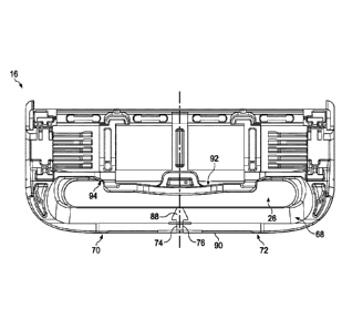
Referring to FIGS. 5A, 5B and 5C the housing 16 is shown with a bridge 88
filling the gap
78 (FIG. 4C) and interconnecting the pair of arms 70 and 72 (e.g., the distal
ends 74 and 76), thus
forming the enclosed opening 26. The bridge 88 and the arms 70 and 72 may form
a front wall 90.
The housing 16 may be injection molded with the first polymeric material and
then a second
polymeric material may be co-injection molded over the first polymeric
material of the housing 16
to interconnect the pair of arms 70 and 72 (e.g., bonding the pair of arms 70
and 72 together). The
second polymeric material may be an thermo-plastic elastomer material to
provide support and
flexibility to the pair of arms 70 and 72. In certain embodiments, the second
polymeric material
88 that forms the bridge 88 may extend over a portion of the top surface 66 of
the housing 16 to
form the skin engaging member 28 and the protrusions 30 (see FIG. 5B). The
bridge 88 may also
cover a portion of the bottom surface 68 to provide extra impact resistance to
help prevent the arms
70 and 72 from being damaged or breaking (e.g., when dropped onto a bathroom
tile floor). The
bridge member 88 may be injection molded from an thermo-plastic elastomer
material which may
further improve impact resistance.
Accordingly, the bridge 88 may not only make the housing 16 more
manufacturable and
impact resistant, but may also form the skin-engaging member 28 and
protrusions 30 on the top
surface 66 of the housing 16 to improve skin stretch during a shaving stroke.
It may be beneficial
for the bridge 88 to interconnect the distal ends 74 and 76, but not cover the
bottom surface 68
because a polymeric material used to improve skin stretching, may not allow
for smooth insertion
of the handle 14 into the opening 26. In certain embodiments, the bridge 88
may comprise a
lubricous material or a water leachable shaving aid that may also cover a
portion of the top surface
66 of the housing 16 (e.g., the skin engaging member 28). A polymeric material
having a lower
coefficient of friction than the housing 16 may improve glide of the skin
engaging member 28 and
may also improve insertion of the handle 12 into the opening 26.
In certain embodiments, the bridge 88 may comprise a polymeric material that
is a different
color than the housing 16. The contrasting color of the bridge 88 and the
housing 16 may act as
an indicator for the consumer to properly insert the handle 14 into the
opening 26. The proper
insertion of the handle 14 may also be aided by the shape of the bridge 88. In
certain embodiments,
the bridge 88 may form a shape, such as an arrow, to indicate the proper
positioning for attaching
the handle 14 to the shaving razor cartridge 12. Accordingly, the bridge 88
may act as a handle
docking alignment member that indicates an intended docking direction for the
handle 14 to be
inserted into the opening 26. The handle docking alignment member (e.g., the
bridge 88) may be
Date Recue/Date Received 2022-07-22
7
on the same surface (e.g., bottom surface 68) that defines the opening 26 for
receiving the handle
14 to be more intuitive to the consumer. The handle docking alignment member
(e.g., the bridge
88) may be positioned along a centerline "CL" of the housing 16. The bottom
surface 68 of the
housing 16 may include a handle locking member 92 (FIG. 5A) that secures a
portion of the handle
14 (FIG. 1) within the opening 26. The handle locking member 92 may be
positioned behind the
handle docking alignment member (e.g., the bridge 88) to indicate the intended
position of the
handle 14 (FIG. 1) for proper attachment with the shaving razor cartridge 12
(FIG. 1). The handle
locking member 92 may be extend from interior wall 94 of the housing 16 extend
over the opening
26.
Referring to FIG. 6, a cross section view of the shaving razor cartridge 12 is
shown. The
bridge 88 may have a thickness "t2" of about 0.5mm to about 15mm and more
preferably about
2mm to about 7mm. The bridge 88 may extend from the bottom surface 68 to the
top surface 66.
The thickness "t2" may be increased to improve the integrity of the shaving
razor cartride 12.
Typically the most hazardous area of the housing 16 to fail is near the blades
32. Accordingly, it
may be beneficial to have the bridge 88 closer to the first blade 32a. A rear
wall 98 of the bridge
88 may be about 2.5mm to about 7mm to a cutting edge 96 of the first blade
32a.
The dimensions and values disclosed herein are not to be understood as being
strictly
limited to the exact numerical values recited. Instead, unless otherwise
specified, each such
dimension is intended to mean both the recited value and a functionally
equivalent range
surrounding that value. For example, a dimension disclosed as "40 mm" is
intended to mean "about
40 mm."
The citation of any document is not an admission that it is prior art with
respect to any
invention disclosed or claimed herein or that it alone, or in any combination
with any other
reference or references, teaches, suggests or discloses any such invention.
Further, to the extent
that any meaning or definition of a term in this document conflicts with any
meaning or definition
of the same term in a document referenced herein, the
meaning or definition assigned to
that term in this document shall govern.
While particular embodiments of the present invention have been illustrated
and described,
it would be obvious to those skilled in the art that various other changes and
modifications can be
made without departing from the spirit and scope of the invention. It is
therefore intended to cover
Date Recue/Date Received 2022-07-22
8
in the appended claims all such changes and modifications that are within the
scope of this
invention.
Date Recue/Date Received 2022-07-22