Note: Descriptions are shown in the official language in which they were submitted.
WO 2021/168462
PCT/US2021/019134
REMEDIATION PROCESSES AND SYSTEMS
Copyright Notice
[0001] 2021 ASRC Energy Services. A portion of the disclosure of this patent
document contains material that is subject to copyright protection. The
copyright
owner has no objection to the facsimile reproduction by anyone of the patent
document or the patent disclosure, as it appears in the Patent and Trademark
Office
patent file or records, but otherwise reserves all copyright rights
whatsoever. 37
CFR 1.71(d).
Cross-Reference to Related Applications
[0002] This application claims priority to U.S. provisional patent application
no
62/979,885 filed February 21, 2020 and entitled "REMEDIATION PROCESSES AND
SYSTEMS," the entire contents of which are hereby incorporated herein by
reference in its entirety.
Technical Field
[0003] This disclosure relates generally to environmental technologies and in
particular to remediation processes and systems.
Background
[0004] Per- and polyfluoroalkyl substance (PFAS) compounds are a large group
of
compounds (> 6,000) that have an alkyl chain. The perfluoroalkyl compounds
have
fluorine (F) atoms bonded to all of the carbon (C) atoms in the alkyl chain
(also
referred to as the backbone). The polyfluoroalkyl compounds have some hydrogen
(H) atoms in addition to F atoms bonded to the C atoms of the alkyl chain.
PFAS
1
CA 03168707 2022- 8- 19
WO 2021/168462
PCT/US2021/019134
compounds have unique surfactant properties. The alkyl tails make these
substances both hydrophobic (water-repelling) and oleophobic/lipophobic
(oil/fat-
repelling).
[0005]Because of these properties, PFAS compounds have been used extensively
in surface coating and protectant formulations. Major applications have
included
protectants that enhance water, grease, and soil repellency for paper and
cardboard
packaging products, carpets, leather products, and textiles. The compounds
also
have been widely used in industrial surfactants, emulsifiers, wetting agents,
additives, and coatings. PFAS compounds have been used in fire-fighting foams
because they are effective in extinguishing hydrocarbon-fueled fires. They are
also
used as processing aids in the manufacture of fluoropolymers, such as nonstick
coatings on cookware, membranes for clothing that are both waterproof and
breathable, electrical wire casing, fire- and chemical-resistant tubing, and
plumbing
thread seal tape.
[0006]The fluorine-carbon bonds in PFAS compounds are very stable and give
these substances high thermal and chemical stability. PFAS compounds are
persistent in the environment. Many PFAS compounds are found worldwide in the
environment, wildlife, and humans. Bioaccumulation of PFAS compounds in
humans is a concern.
[0007]A need exists for alternative remediation processes and systems for
removing
PFAS compounds from contaminated materials.
Brief Description of the Drawings
[0008]The embodiments disclosed herein will become more fully apparent from
the
following description and appended claims, taken in conjunction with the
2
CA 03168707 2022- 8- 19
WO 2021/168462
PCT/US2021/019134
accompanying drawings. The drawings depict primarily generalized embodiments,
which embodiments will be described with additional specificity and detail in
connection with the drawings in which:
[0009] FIG. 1 illustrates an exemplary embodiment of a system for removing a
PFAS
compound from contaminated material.
[0010] FIG. 2 illustrates an exemplary variation of the embodiment illustrated
in FIG.
1.
[0011]FIG. 3 illustrates an exemplary variation of the embodiment illustrated
in FIG.
1.
[0012] FIG. 4 illustrates an exemplary variation of the embodiment illustrated
in FIG.
1.
[0013] FIG. 5 illustrates an exemplary variation of the embodiment illustrated
in FIG.
1.
[0014] FIG. 6 illustrates an exemplary variation of the embodiment illustrated
in FIG.
1.
[0015] FIG. 7 illustrates an exemplary variation of the embodiment illustrated
in FIG.
1.
[0016] FIG. 8 illustrates another exemplary embodiment of a system for
removing a
PFAS compound from contaminated material.
[0017] FIG. 9 illustrates an exemplary variation of the embodiment illustrated
in FIG.
8.
[0018] FIG. 10 is a cross-section diagram illustrating an exemplary embodiment
of a
system for removing a PFAS compound from contaminated material.
3
CA 03168707 2022- 8- 19
WO 2021/168462
PCT/US2021/019134
[0019] FIG. 11 is a cross-section diagram of a scale model of an exemplary
rotatable
barrel illustrating advancing flights and lifting flights in accordance with
the present
disclosure.
[0020] FIG, 12 is a graph showing the concentration of PFAS compounds in
untreated soil samples collected from four collection sites.
[0021] FIG. 13 is a graph showing the concentration of six regulated PFAS
analytes
based on treatment degree-minutes above 500 F in soil samples treated in
accordance with an embodiment of the present disclosure.
[0022] FIG. 14 is a graph showing the concentration of the six regulated PFAS
analytes from FIG. 13 based solely on treatment temperature.
[0023] FIG. 15 is a graph showing the concentration of the six regulated PFAS
analytes based solely on treatment time.
[0024] FIG. 16 is a graph showing temperature signatures of a desorption
treatment
in accordance with an embodiment of the present disclosure.
Detailed Description
[0025]Disclosed herein are processes and systems for remediation of per- and
polyfluoroalkyl substance (PFAS)-contaminated material.
[0026] The binding of PFAS compounds to different materials is governed to a
large
extent by the surface-active behavior of the PFAS compounds. The fluorinated
backbone is both hydrophobic (water repelling) and oleophobidlipophobic
(oil/fat
repelling) while the terminal functional group is hydrophilic (water loving).
This means
that PFAS compounds tend to partition to interfaces, such as between air and
water
with the fluorinated backbone residing in air and the terminal functional
group residing
in water. The PFAS partitioning behavior also is affected by the alkyl chain
length and
4
CA 03168707 2022- 8- 19
WO 2021/168462
PCT/US2021/019134
the charge on the terminal functional group. In general, PFAS compounds with a
shorter alkyl chain length are more water soluble than those with longer
lengths.
Adsorption to soil surfaces tends to be greater for PFAS compounds with longer
alkyl
chain length.
[0027]At environmentally relevant pH, many PFAS compounds have a negatively
charged terminal functional group (i.e., anionic), meaning that they will be
repelled
from soil that tends to have negatively charged surfaces. Some PFAS compounds
have a positively charged terminal functional group (i.e., cation), which
strongly bind
with soils. And a few PFAS compounds have both positively and negatively
charged
groups (i.e., zwitterions), which will exhibit partitioning behavior between
anionic and
cationic compounds.
[0028]The processes and systems disclosed herein for remediation of PFAS
compounds can address the unique characteristics of PFAS compounds.
[0029]The phrase "operably connected to" refers to any form of interaction
between
two or more entities, including mechanical, electrical, magnetic,
electromagnetic, fluid,
and thermal interaction. Two entities may interact with each other even though
they
are not in direct contact with each other. For example, two entities may
interact with
each other through an intermediate entity.
[0030] Disclosed herein are processes and systems for remediation of a per-
and
polyfluoroalkyl substance (PFAS) compound-contaminated material. For example,
the remediation processes may include receiving a feed stream comprising a
PFAS
compound-contaminated material, introducing the material into a vessel, and
heating
the material in the vessel for at least 2000 degree F * minutes above 500 F
to
reduce the PFAS compound present in the material below a selected level. As
used
herein, "degree F * minutes above 500 F" is a measure of the area under the
curve
CA 03168707 2022- 8- 19
WO 2021/168462
PCT/US2021/019134
of a plot of the temperature of the material above 500 F and the time of the
material
in the vessel at temperatures above 500 F. Stated another way, "degree F*
minutes above 500 F" is the integral of the temperature versus time function
with a
lower limit of 500 F. The degree F * minutes above 500 F encompasses the
various combinations of temperature and time to achieve a stated "degree F *
minutes". For example, 2000 degree F * minutes above 500 F may be achieved by
the material being at 1000 F for four minutes or by the material being at
1500 F for
two minutes. The degree F * minutes above 500 F may be approximated by
summing the average temperatures of the material above 500 F for each minute
the
material is above 500 F, or by summing average or representative sample
temperatures of the material above 500 F for any shorter or longer period of
time.
[0031] It may be beneficial to heat the vessel to at least 1200 F to achieve
sufficient
heat transfer to the material.
[0032] The process may include, prior to the heating step, determining a
minimum
degree F * minutes above 500 F needed to reduce the PFAS compound present in
the material below a selected level. That step can include determining
specific
PFAS compounds, chemical types, or both present in the material and their
concentration and utilizing a lookup table to determine the minimum degree F *
minutes above 500 F needed for the specific PFAS compounds. Chemical types
refers to subcategories of PFAS compounds based on chemical features, such as
the type of charge of the terminal functional group, alkyl chain length, etc.
This
determining step may be manual or automatic using the lookup table. The lookup
table may be built by testing samples of the material or by testing other
samples.
Determining the minimum degree F* minutes above 500 F needed to reduce the
6
CA 03168707 2022- 8- 19
WO 2021/168462
PCT/US2021/019134
PFAS compound present in the material below the selected level may include
performing a bench test on a sample of the material.
[0033] Maintaining the material in the vessel for at least 2000 degree F *
minutes
above 500 F may include maintaining the material in the vessel for at least
2500
degree F* minutes above 500 F, at least 3000 degree F * minutes above 500 F,
at
least 3500 degree F * minutes above 500 F, at least 4000 degree F * minutes
above
500 F, at least 4500 degree F * minutes above 500 F, or at least 5000 degree
F *
minutes above 500 'F.
[0034] The process may be a continuous, batch, or semi-batch process. In
continuous processes, the time spent in the vessel refers to the mean
residence time
for the material as opposed to a specific residence of any particular
particle.
[0035] The temperature of the material may be directly measured, indirectly
measured, or determined by modeling. The temperature of the vessel and of the
air
may be measured but those values will generally be different from the
temperature of
the material in the vessel.
[0036] Heating the vessel may include uniformly circumferentially heating the
vessel,
such as via indirect heat. For example, electrical induction coils may be used
to heat
the vessel.
[0037] The process may include mixing the material within the vessel while
maintaining close contact between the material and the interior surface of the
vessel.
For example, the vessel may include a rotatable barrel and the process may
include
rotating the material within the vessel while maintaining close contact
between the
material and the interior surface of the rotatable barrel. Close contact
between the
material and the interior surface aids in heat transfer to the material when
the vessel
is indirectly heated. This is in contrast to a direct-fired dryer which
optimizes heat
7
CA 03168707 2022- 8- 19
WO 2021/168462
PCT/US2021/019134
transfer to a material by having the hot gas in contact with aerated material
solids. In
further distinction from a direct-fired dryer, the vessels disclosed herein
(e.g.,
rotatable barrel) may continuously receive atmospheric air (i.e., unheated
air) into
the vessel during operation (although in some embodiments the feed air may be
partially pre-heated, such as up to 350 F). Close contact with the interior
surface of
the vessel does not require continuous contact but is greater contact than is
achieved by aeration.
[0038] Reducing the PFAS compound present in the material below the selected
level may include reducing the PFAS compound present to less than 1 microgram
of
PFAS compound per kilogram of material or to some other level set by a
regulatory
body. Additionally or alternatively, reducing the PFAS compound present may
include reducing the PFAS compound present by at least 95%, at least 10 fold,
at
least 100 fold, or at least 1000 fold.
[0039] The processes may further include separating vapors containing a PFAS
compound or partially-decomposed PFAS compound hydrocarbons (e.g.,
halogenated hydrocarbons) from the material into an impure vapor stream and
producing a purified solids stream. Optionally, the impure vapor stream may be
condensed to separate a condenser liquid stream from the impure vapor stream.
At
least a portion of the condenser liquid stream may be recycled to the vessel.
Additionally or alternatively, at least a portion of the hydrocarbons from the
condenser liquid stream may be removed, such as for use in combustion to
generate
electricity for the process, commercial sale, or reinjection. The processes
may
further include removing at least a portion of acid gases from the impure
vapor
stream. The process may further include removing particulate matter from the
impure vapor stream. Removal of hydrocarbons and acid gases may be
8
CA 03168707 2022- 8- 19
WO 2021/168462
PCT/US2021/019134
accomplished via condensation, absorption, or filtering. For example,
Applicant has
discovered that when heating the material in the vessel for at least 2000
degree F *
minutes above 500 F, the PFAS compound present in the material can largely be
volatized into the exhaust stream (a.k.a., impure vapor stream). In such
scenarios,
the PFAS compounds (and/or partially-decomposed PFAS compounds) in the
exhaust stream can be captured by removing particulate solids from the exhaust
stream and by condensing liquids out of the exhaust stream. In such
embodiments,
it may not be necessary to use an afterburner (i.e., thermal oxidizer) to
destroy the
PFAS compounds. That said, the removal processes discussed in this paragraph
may be performed after a thermal oxidation step at 1800 F to 2300 'F. One of
skill
in the art with the benefit of this disclosure would understand different
removal
methodologies that could be used. The overarching goal of the separation
process
is to recover the impurities and provide an environmentally safe exhaust vapor
stream.
[0040]A portion of the purified solids stream may be recycled back into the
vessel.
This may aid in preheating the feed stream and/or may reduce the concentration
of
the PFAS compound in the purified solids stream. For example, it may be
desirable
to have at least 96% of the purified solids stream meet clean-up standards
(e.g.,
PFAS concentration less than a selected level, such as 1 pg/kg).
[0041]The processes may further include operating the vessel at a negative
pressure while heating the material. For example, as discussed above,
atmospheric
air may be continuously drawn into the vessel during steady-state operation.
[0042]The processes may further include preheating the material contaminated
with
the PFAS compound sufficient to volatilize at least a portion of the moisture
in the
material prior to introducing the material into the vessel.
9
CA 03168707 2022- 8- 19
WO 2021/168462
PCT/US2021/019134
[0043] One or more additive streams, one or more liquid or solid streams from
other
parts of the process, or combinations thereof may be mixed with the PFAS
compound-contaminated material in the feed stream, prior to introducing the
material
into the vessel. These mixing steps may be used to modify the pH of the feed
material to enhance dissociation of particular chemical types of PFAS
compounds
from certain types of materials (e.g., soil, gravel, etc.) and/or to raise the
pH of the
exhaust stream(s) to reduce corrosion of process equipment. These mixing steps
may also be used to modify the moisture content of the feed material depending
upon the aqueous solubility of the particular chemical type of PFAS compounds
in
the feed material. Additionally, these mixing steps may be used to increase
the
overall destruction of PFAS compound by the processes.
[0044] The processes may include determining a chemical type of the PFAS
compound in the material (e.g., alkyl chain length and the charge on the
terminal
functional group). The process may then be modulated to achieve adequate
destruction and/or removal of the PFAS compound, based on the physical
properties
(e.g., aqueous solubility, vapor pressure) of the type. Exemplary systems for
removing a PFAS compound include a vessel configured to receive a feed stream
containing PFAS-contaminated material, the vessel comprising a rotatable
barrel
having a receiving end, a discharging end, an interior surface, and an
exterior
surface, the rotatable barrel operably coupled to a heater configured to
indirectly,
circumferentially heat the rotatable barrel to at least 1200 F, and the
rotatable barrel
configured to maintain the material in the interior of the rotatable barrel
for a
sufficient period of time to reduce a concentration of the PFAS in the
material below
a selected level.
CA 03168707 2022- 8- 19
WO 2021/168462
PCT/US2021/019134
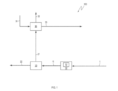
[0045]For example, FIG. 1 illustrates a system 100 for removing a PFAS
compound.
System 100 includes a feed stream 1 containing a PFAS compound-contaminated
material. A vessel 10 is operably coupled to a heater 12 (e.g., an inductive
or other
heater). The vessel 10 may be comprised of different materials. For example,
in
some embodiments the vessel may be comprised wholly or partially of graphite
or
stainless steel. The heater 12 is configured to indirectly heat material
received in the
vessel to a minimum or predetermined temperature. For example, in some
embodiments the heater is configured to heat material received in the vessel
to at
least 1200 F. In some embodiments, the heater is configured to heat material
received in the vessel to at least 1250 F, 1300 F, 1350 F, 1400 F, 1500
F, 1600
F, 1700 F, 011800 F, such as 1200 F to 1800 F, 1200 F to 2200 F, 1200 F to
2000 F, or 1200 F to less than 2000 F. In some embodiments, rather than
being
configured to heat material to at least these temperatures, the heater is
configured to
heat the vessel to an operating temperature of at least 1200 F, 1250 F, 1300
F,
1350 F, 1400 F, 1500 F, 1600 F, 1700 F, 1800 F, 1900 F, 2000 F, 2200
F,
2400 F, such as, 1200 F to 2400 F, 1200 F to 2200 F, 1200 F to 2000 F,
or
1200 F to less than 2000 F, or other minimum operating temperature. The
system
100 is configured to maintain the material in the vessel 10 for a sufficient
period of
time to reduce a concentration of the PFAS compound in the material below a
selected level. Or stated another way, the system 100 is configured to achieve
a
residence time of the material in the vessel 10 for a sufficient period of
time to
reduce a concentration of the PFAS compound in the material below a selected
level. The selected level may be set by an operator of the system 100.
11
CA 03168707 2022- 8- 19
WO 2021/168462
PCT/US2021/019134
[0046] The feed stream 1 may be at atmospheric temperature and pressure. In
addition to the PFAS compound-contaminated material, the feed stream 1 may
include fresh air. Alternatively, fresh air may be separately supplied to the
vessel 10.
[0047] The PFAS compound-contaminated material may include different PFAS
compounds or may be contaminated with only one PFAS compound.
[0048] The material may be any type of material contaminated with a PFAS
compound, such as, for example, soil, gravel, rock, and other solid media. The
system 100 further includes a separator 20 operably connected to the vessel
10.
The separator 20 is configured to separate heated material in output stream 11
from
the vessel 10 into an impure vapor stream 21 and a purified solids stream 22.
The
output stream 11 may be at negative pressure (i.e., a pressure less than
atmospheric pressure). The output stream 11 may be 1200 F to 2500 F, such as
1300 F.
[0049] The system 100 further includes a scrubber 30 operably connected to the
impure vapor stream 21. In the embodiment illustrated in FIG. 1, the scrubber
30
includes a wet scrubber and is configured to receive an aqueous input stream
31
and to produce a purified vapor stream 32 and a scrubber liquid stream 33.
Other
embodiments may include different types of scrubbers, such as dry or semi-dry
scrubbers.
[0050]Although not illustrated, the system 100 may include temperature,
pressure,
moisture, and pH controllers using feedback and feed-forward control systems
and
corresponding sensors throughout the system 100. For example, the separator 20
may be operably connected to temperature, pressure, and moisture controllers.
In
another example, the scrubber 30 may be operably connected to temperature,
12
CA 03168707 2022- 8- 19
WO 2021/168462
PCT/US2021/019134
pressure, and pH controllers. Additionally, the system 100 may include PFAS
concentration detection mechanisms that feed data to control systems.
[0051 ] FIG. 2 illustrates a system 100a, which includes all the features of
the system
100. Additionally, the system 100a includes a blower 40 operably connected to
the
purified vapor stream 32 and configured to generate negative pressure in the
scrubber 30, the impure vapor stream 32, and the vessel 10. The blower 40
produces exhaust vapor stream 41. The exhaust vapor stream 41 may be
controlled
to be at atmospheric temperature and pressure. In this embodiment, the
scrubber
30 and the vessel 10 (and interconnecting streams and subsystems) are
configured
for operation at negative pressure.
[0052] The system 100a also includes a flow diverter 24 operably connected to
the
purified solids stream 22 and configured to direct all, a portion, or none of
the purified
solids stream 22 (via solid recycle stream 23) to the feed stream 1 at a point
upstream from the vessel 10. For example, the flow diverter 24 may be an
adjustable gate (such as made from a high-temperature compatible superalloy)
configured to variably partition the purified solids stream 22 as desired. In
certain
embodiments, the recycle ratio ranges from 0.1 to 0.9. It should be understood
that
the purified solids stream 22 and the solid recycle stream 23 may be at least
partially
molten or liquified; however, upon cooling to atmospheric temperature, the
contents
of the streams may be solid or partially solid in nature.
[0053] The system 100a also includes a controller 60 operably connected to the
scrubber liquid stream 33 and configured to direct all, a portion, or none of
the
scrubber liquid stream 33 (via liquid scrubber stream 34) to the feed stream 1
at a
point upstream from the vessel 10, which may be the same or different from the
point
at which the solid recycle stream 23 encounters the feed stream 1.
13
CA 03168707 2022- 8- 19
WO 2021/168462
PCT/US2021/019134
[0054] In certain embodiments, the liquid scrubber stream 34 may not be
present.
For example, it may be preferable to further process and/or dispose of the
liquid
scrubber stream 33.
[0055] FIG. 3 illustrates a system 100b, which also includes all the features
of the
system 100. Additionally, the scrubber 30 in the system 100b is configured to
receive an additive stream 35. For example, sodium hydroxide or other
neutralizers
may be an additive used to remove acid gases. The additive stream 35 is
illustrated
as separate from the clean water input stream 31 but may be combined with the
clean water input stream 31. In the embodiment illustrated in FIG. 3, the
scrubber 30
is configured to produce a solid precipitant in a solid scrubber stream 36.
[0056] The system 100b includes a controller 39 operably connected to the
solid
scrubber stream 36 and configured to direct all, a portion, or none of the
solid
scrubber stream 36 (via solid scrubber stream 37) to the feed stream 1 at a
point
upstream from the vessel 10, which may be the same or different from the point
at
which the solid recycle stream 23 encounters the feed stream 1 and the same or
different from the point at which the liquid scrubber stream 34 encounters the
feed
stream 1.
[0057] In certain embodiments, the solid scrubber stream 37 may not be
present.
For example, when the additive is limestone (calcium carbonate) and the solid
scrubber stream 36 is primarily gypsum (calcium sulfate), it may be preferable
to
stockpile the gypsum for later disposal or sale.
[0058] It should be understood that any controller known in the art, such as a
three-
way valve, and compatible with the materials being handled may be used as the
controller 39. This also applies to the other flow controllers and diverters
disclosed
herein.
14
CA 03168707 2022- 8- 19
WO 2021/168462
PCT/US2021/019134
[0059] FIG. 4 illustrates a system 100c, which also includes all the features
of the
system 100b. In the system 100c, the liquid scrubber stream 34 and the solid
scrubber stream 37 combine with the feed stream 1 in a mixer 80 to produce a
modified feed stream 81. In the illustrated embodiment of FIG. 4, an additive
stream
82 also feeds into the mixer 80.
[0060] Various types of mixers may be used, depending on the range of
materials to
be processed, such as, by way of non-limiting example, augers or other rotary
mixers. Where the system 100c may be designed for handling a variety of
materials,
then it may be desirable to provide a mixer that is sufficiently robust for
the most
difficult of materials. This can be particularly true when the system 100c is
configured for mobile operation and use at multiple sites.
[0061] The mixer 80 (and the overall system 100c) may be configured with
multiple
connections for numerous inputs and outputs that may not all be used at each
site
and for each type of PFAS compound. For example, for a site contaminated with
a
PFAS compound that is highly water soluble, such as perfluorooctanoic acid
(PFOA)
with an estimated water solubility of 9,500 mg/L, it may be desirable to
increase the
moisture content of the feed stream 1. This could be done via the additive
stream
82, the liquid scrubber stream 34, or other liquid streams in the system.
Additionally,
when the material is soil, it may be desirable to maintain the pH of the PFOA-
contaminated material at environmental pH to maintain repulsion of the PFOA
from
the soil.
[0062] In another example, for a site with soil contaminated with a PFAS
compound
that is less water soluble, such as perfluorooctane sulfonate (PFOS) with an
estimated water solubility of 680 mg/L, it may not be beneficial to increase
the
moisture content of the feed stream 1. However, it may be beneficial to tailor
the pH
CA 03168707 2022- 8- 19
WO 2021/168462
PCT/US2021/019134
of the feed stream 1 to enhance repulsion of the PFOS from the soil. In that
example, the mixer 80 may include connections to the liquid scrubber stream
34.
That said, those connections may not be used and/or the controller 38 may
prevent
any flow into the liquid scrubber stream 34.
[0063] FIG. 5 illustrates a system 100d, which also includes all the features
of the
system 100b. The system 100d includes a mill 90 operably connected to the feed
stream 1 at a point upstream from the vessel 10 and configured to crush the
PFAS
compound-contaminated material in the feed stream to a desired size. In the
illustrated embodiment of FIG. 5, the mill 90 is upstream of the mixer 80 and
produces a milled feed 91. Non-limiting examples of the mill 90 include ball
mills and
hammer mills.
[0064] FIG. 6 illustrates a system 100e, which also includes all the features
of the
system 100b. The system 100e includes a preheater 95 operably connected to the
feed stream 1 at a point upstream from the vessel 10 and configured to at
least
partially volatilize moisture present in the PFAS compound-contaminated
material in
the feed stream 1. In the illustrated embodiment of FIG. 6, the preheater 95
is
upstream of the mixer 80 and produces a preheated feed 96. Alternatively or
additionally, a portion of recycled purified solids stream 22 may be used to
preheat
the feed stream 1.
[0065] In particular embodiments, the preheater 95 may be a tank or steel box
with
steam-pipes running through it and/or an access port connected to an air-
heater too.
In such embodiments, this portion of the system would likely be operated as a
batch
process. For example, a batch of the material in the feed stream 1 may be
heated
for 8 to 24 hours. The preheated feed 96 may then be continuously or batch-
wise
fed to the mixer 80.
16
CA 03168707 2022- 8- 19
WO 2021/168462
PCT/US2021/019134
[0066] FIG. 7 illustrates a system 100f, which also includes all the features
of the
system 100b. The system 100f includes a condenser 25 operably connected to the
impure vapor stream 21 upstream of the scrubber 30. The impure vapor stream 21
may be similar in temperature to the output stream 11. The impure vapor stream
21
may contain acid gases, PFAS compound, partially-decomposed PFAS compound
hydrocarbons, other hydrocarbons, and trace solids. The condenser 25 is
configured to separate a condenser liquid stream 26 from the impure vapor
stream
21 to produce a simplified impure vapor stream 27.
[0067] The condenser liquid stream 26 may include contaminated water and/or
the
PFAS compound or partially-decomposed PFAS compound hydrocarbons. The
condenser liquid stream 26 may also include hydrocarbons from other sources,
such
as from other organic compounds in the material.
[0068] The simplified impure vapor stream 27 may contain acid gases and
residual
PFAS compound or hydrocarbons. In some embodiments, the simplified impure
vapor stream 27 is at a negative pressure and/or at a temperature less than
212 F.
[0069] The system 100f includes a controller 29 operably connected to the
condenser liquid stream 26 and configured to direct all, a portion, or none of
the
condenser liquid stream 26 (via condenser liquid stream 28) to the feed stream
1 at
a point upstream from the vessel 10. In the illustrated embodiment of FIG. 7,
the
condenser liquid stream 28 feeds into the mixer 80.
[0070] The presentation of different system features in FIGs. 1-7 is not
limiting. It
should be understood that in different embodiments any or none of the features
shown in FIGs. 1-7 may be combined with each other, even if not specifically
illustrated. For example, a system 100 in various embodiments may be modified
to
include one or more of the controller 60 and flow diverter 24 illustrated in
Figure 2.
17
CA 03168707 2022- 8- 19
WO 2021/168462
PCT/US2021/019134
In other embodiments, a system may similarly have one or more of any system
feature shown in FIGs. 1-7.
[0071] FIG. 8 illustrates another embodiment of a system 200 for removing a
PFAS
compound. The system 200 includes all of the features of the system 100,
except
that a separator 20 as a distinct unit operation is not present. Instead, the
vessel
110 (operably coupled to heater 112, which in some embodiments is an inductive
heater) includes a vent configured to release an impure vapor stream 121 from
the
vessel 110 and thereby separate vapors from the solids in the material. The
vessel
is also configured to produce a purified solids stream 122.
[0072] The scrubber 130 includes the same streams and options as the scrubber
30
in the system 100.
[0073] FIG. 9 illustrates a system 200a, which includes all the features of
the system
200. The system 200a includes an afterburner 123 operably coupled to the
vessel
110, such as via the vent. The afterburner 123 is configured to burn
combustible
vapors and gases in the impure vapor stream 121. "Combustible vapors and
gases"
refers to vapors and gases capable of combustion at the operating temperature
of
the afterburner. The afterburner 123 may operate at a temperature greater than
1800 F, such as 2000 F to 2500 'F.
[0074] The afterburner 123 is illustrated as separate from the vessel 110 but
can be
directly connected to the vessel 110. The afterburner 123 produces a flue gas
stream 124, which is operably coupled to the scrubber 130. The afterburner 123
may be used instead of a condenser. Alternatively, a condenser may still be
operably coupled to the flue gas stream 124.
[0075] I n embodiments that include the afterburner, the vessel 110 (or the
vessel 10)
may only be heated to 1500 F, such as 1200 F to 1500 F. Relatedly, when
using
18
CA 03168707 2022- 8- 19
WO 2021/168462
PCT/US2021/019134
the afterburner, the heater may be configured to heat material received in the
vessel
to 1500 F, such as 1200 F to 1500 F.
[0076]All of the options discussed above regarding the system 100 and FIGs. 2-
7
apply to the system 200. Likewise, all of the options discussed above
regarding the
system 200 and FIGs. 8 and 9 apply to the system 100. For example, an
afterburner
may be operably coupled to the separator 20 and configured to burn combustible
vapors and gases in the impure vapor stream 21.
[0077]The system 100 and the system 200 may be configured for mobile
operation,
such that the systems may be moved from site-to-site. The system components
may
be configured and sized for transport by tractor-trailer, such as by flatbed,
or by
shipping container, such as a standard forty foot shipping container.
[0078]In certain embodiments, the systems and processes disclosed herein are
configured for operation at temperatures lower than the incineration
temperatures for
the chemical type of PFAS in the material. Meanwhile, in such embodiments, the
flue gas produced may be cleaner than that produced by incineration (e.g., the
amount of PFAS released into the atmosphere may be less and/or the amount of
fluorinated by-products released to atmosphere may be less). Therefore,
certain
embodiments of the systems and processes disclosed herein may use less energy
than incineration (due to lower temperatures) and may be safer for the
environment.
[0079] FIG. 10 illustrates a system 1000 for removing contaminants. The system
1000 can be used as the vessel 10 and the heater 12 (or the vessel 110 and the
heater 112) in any of the embodiments of FIGs. 1-9. The system 1000 includes a
rotatable barrel 1010 having a receiving end 1012, a discharging end 1014, an
interior surface 1016, and an exterior surface 1018. The rotatable barrel 1010
is
operably coupled to a heater 1020 comprising an induction coil 1022 configured
to
19
CA 03168707 2022- 8- 19
WO 2021/168462
PCT/US2021/019134
indirectly, circumferentially heat the rotatable barrel 1010 to varying
temperatures,
such as at least 1350 F.
[0080] In this illustrated embodiment, the rotatable barrel 1010 is configured
for
horizontal operation. The interior surface 1016 of the rotatable barrel 1010
comprises lifting flights (not illustrated) configured to aid in circulating
material within
the rotatable barrel 1010 and advancing flights 1026 configured to advance
material
from the receiving end 1012 to the discharging end 1014.
[0081] In this embodiment, the length of the lifting flights (see, e.g., FIG.
11) is axially
aligned with a longitudinal axis of the rotatable barrel 1010 and the lifting
flights
protrude from and are circumferentially spaced around the interior surface
1016 of
the rotatable barrel 1010. The height of the lifting flights may be less than
the height
of the advancing flights, such as a two-thirds ratio. Additionally, the
lifting flights may
have a negative angle of repose. The "angle of repose" (AOR) is the angle of a
lifting flight (LF) with respect to the central longitudinal axis of rotation
in the rotatable
barrel. If the LFs point straight towards intersecting the longitudinal axis,
this is
considered a zero degree AOR. If the LFs are angled "down" (below the central
axis), the LFs have a negative AOR, while LFs angled "up" (above the central
axis)
have a positive AOR.
[0082] In the illustrated embodiment, the length of the advancing flights 1026
is
orientated transverse to the lifting flights and the advancing flights 1026
protrude
from and are helically spaced around the interior surface 1016 of the
rotatable barrel
1010.
[0083] The system 1000 includes a rotary mechanism (and rotary support
structure)
1028 operatively coupled to the rotatable barrel 1010. In particular
embodiments,
CA 03168707 2022- 8- 19
WO 2021/168462
PCT/US2021/019134
the rotary mechanism 1028 is configured to rotate the rotatable barrel 1010 at
a
speed of one to eight rotations per minute.
[0084] In the system 1000, the heater 1020 includes an induction coil
circumscribing
the exterior surface 1018 of the rotatable barrel 1010.
[0085] System 1000 includes a feed hopper 1030 operatively coupled to the
receiving end 1012 of the rotatable barrel 1010.
[0086] In the illustrated embodiment, the system 1000 fits within a standard
forty foot
shipping container. For certain barrel diameters, the rotatable barrel 1010
must be
configured to be parallel to the floor and ceiling of the shipping container
(i.e.,
configured for horizontal operation), to allow room for the induction coils of
heater
1020, the rotary mechanism (and rotary support structure) 1028, and the feed
hopper 1030. In such embodiments, the rotatable barrel 1010 may include
lifting
flights and advancing flights (such as lifting flights 1124 and advancing
flights 1 026
or 1126).
[0087] By way of non-limiting example, the system 1000 may be used with solid
and
semi-solid materials with a wide array of particle size distributions, soil
types, organic
content, and moisture content.
[0088] In addition to the system 1000 being in a shipping container, a mobile
multi-
tap transformer and associated switchgear can also be in a separate shipping
container. The transformer can be used to connect a high voltage power supply
to
the system 1000.
[0089]Additionally, a third shipping container may contain the process
equipment for
cleaning the vapor-phase effluent (e.g., impure vapor stream 21 or 121)
exiting the
rotatable barrel 1010. The third shipping container may include a cyclone and
baghouse for removing particulate matter from the impure vapor stream 21 or
121,
21
CA 03168707 2022- 8- 19
WO 2021/168462
PCT/US2021/019134
afterburner, and quench cooler. Alternatively, in embodiments where the
contaminants are sufficiently destroyed in the rotatable barrel 1010, the
third
shipping container does not include the afterburner.
[0090] In an alternative to the illustrated embodiment, the rotatable barrel
may be
configured for declined angle operation. In such embodiments, the interior of
the
rotatable barrel would include lifting flights configured to aid in
circulating material
within the rotatable barrel but would not necessarily need advancing flights.
[0091] In any of the systems disclosed herein, a sufficient period of time to
reduce
the concentration of the PFAS in the material below the selected level may
involve
maintaining the material in the vessel (such as the rotatable barrel) for at
least 2000
degree F * minutes above 500 'F.
[0092] Without further elaboration, it is believed that one skilled in the art
can use the
preceding description to utilize the present disclosure to its fullest extent.
The
examples and embodiments disclosed herein are to be construed as merely
illustrative
and exemplary and not a limitation of the scope of the present disclosure in
any way.
It will be apparent to those having skill in the art, and having the benefit
of this
disclosure, that changes may be made to the details of the above-described
embodiments without departing from the underlying principles of the disclosure
herein.
Examples
Example 1 ¨ Barrel Scale Model Testing
[0093]Scale models of rotatable barrels in accordance with the present
disclosure
were 3-D printed with different flighting options to evaluate effects of
flight design on
the movement of soil through the vessel. The tested configurations are listed
in Table
1.
22
CA 03168707 2022- 8- 19
WO 2021/168462
PCT/US2021/019134
DUT Flighting AF AF AF AF #ang. IF IF #
axial IF IF AOR
type Pitch Height Length Itsections LFs Height Length
sections (-deg)
1 FULL 6 4 120 1 6 4.5 120 1
20
2 FULL 6 4 120 1 6 2 120 1
20
3 AGP 6 4 18 4 4 2 120 1
20
4 AGP 12 4 24 2 8 2 12 6
20
ARGP 6 4 12 5 3 4 120 1 0
Table 1. Flighting configurations of five devices under test (DUTs) tested for
material
retention time. AF = advancing flight; AGP = axial gap (longitudinal regions
without
advancing flights); AOR = angle of repose; ARGP = axial radial gap
(longitudinal
regions without advancing flights, plus discontinuous helices of the advancing
flights); LF = lifting flight.
[0094] To the extent possible, the models were printed to 1/25.4 scale
(original
dimensions in inches, model dimensions in mm). Each device under test (DUT)
was
placed in a 3-D printed fixture and driven by a stepper motor belt drive. The
fixture
was put on a 3-D printed leveling plate equipped with four M3 screws having a
pitch
of 0.5 mm for use in adjusting the declination angle (tilt) of the plate. The
two rows of
M3 screws were 140 mm apart, so the declination angle was calculated by taking
the
arctangent of the height difference in the two rows of screws, divided by 140
mm.
The height difference was found by counting turns of the M3 screws. A digital
level
was used to identify the horizontal configuration, and to double-check the
calculated
declination angle. Play sand, i.e., the type used in children's sandboxes, was
used
to simulate soil samples. Each trial was performed according to the following
protocol:
1. Pick up the entire test fixture and tilt it so that the barrel opening is
pointing
up;
23
CA 03168707 2022- 8- 19
WO 2021/168462
PCT/US2021/019134
2. Add 1 tablespoon of sand and shake the test fixture until all sand has
settled to the bottom;
3. Place the DUT on the work bench so that the video camera is aimed down
the barrel;
4. Record the DUT number, RPM setting, declination angle, and trial number
5. Start recording video;
6. Connect the stepper controller to 12 V power to start it;
7. Run the stepper motor until sand is no longer exiting the barrel;
8. Save the video file; and
9. Dump the sand from the leveling table into the sample receptable and
clean out the DUT before running the next trial.
[0095]The number of revolutions needed to move the entire sand sample through
the
DUT was measured by counting the number of revolutions (200 steps per
revolution)
of the stepper motor for each trial. The volume of the sand sample was
measured with
a teaspoon (1 tsp = 5 ml). If a significant amount of sand remained stuck in
the vessel
after the trial, this was noted in the results.
[0096]The rotational speed in rpm was calculated from the motor's steps per
revolution and held constant throughout each trial. Trials were run at two
speeds (6
rpm and 30 rpm), to observe whether rotational speed had a significant effect
on the
number of revolutions it took for the sand to traverse the vessel.
[0097] Sand samples were found to traverse through each of the DUTs at rates
having
varied dependence on inclination angle. One of the DUTs tested ("DUT 2" in
Table 1,
a cross-section diagram of which is shown in FIG. 11), had one continuous
helical
advancing flight 1126 (pitch = 6; height = 4 mm) and six 2 mm high lifting
flights 1124
having a -20 angle of repose (AOR). The advancing and lifting flights each
extended
24
CA 03168707 2022- 8- 19
WO 2021/168462
PCT/US2021/019134
substantially the full length of the vessel barrel (120 mm). This DUT moved
sand in a
predictable manner, taking about 12-13 revolutions to distribute the sand into
its flights
and 8-9 more revolutions to evacuate all flights. These results were
substantially
independent of inclination angle.
[0098] By contrast, DUT 1, which has 4.5 mm tall lifting flights (0.5 mm
taller than the
4 mm helical advancing flights), did not evacuate all its dirt in nearly 100
revolutions.
It appears that because the lifting flights were taller than the advancing
flights, the dirt
did not follow the advancing flights well, instead simply tumbled over them.
[0099] DUTs 3, 4 and 5 only used a few advancing flights and relied on
declination
angle plus the agitation caused by the lifting flights to move the dirt down
the barrel.
These DUTs needed a declination angle to function properly, and the number of
revolutions needed to evacuate all the dirt was dependent on how large the
declination
angle was.
[00100] No strong correlation was found between RPM and the number of turns
needed to evacuate dirt from the barrel.
Example 2 ¨ PFAS Desorption Bench Scale Testing
[00101] A bench test was designed and executed to evaluate the potential to
desorb
six regulated PFAS compounds from contaminated soil to below regulatory
limits, as
well as to evaluate the characteristics of the treatment technology. The
process used
to determine the degree F * minutes above 500 F useful for these example
samples
can be applied to other soils and to other compounds.
A. Bench Scale Treatment Unit Description
[00102] The bench scale treatment unit consisted of a variable speed rotating
reaction chamber (barrel), a scaled induction heating unit, a controlled air
flow system,
as well as ancillary equipment to maintain system operations. The bench unit
allowed
CA 03168707 2022- 8- 19
WO 2021/168462
PCT/US2021/019134
the manipulation of several variables including the barrel wall temperature,
air supply
temperature, air flow rate, time that the reaction chamber was at target
temperature
(residence time), and barrel rotation rate. In addition to the control and
measurement
of these variables, moisture in the soil, pressure inside the barrel, air
samples, and
several other data points were captured both digitally and by hand. The bench
scale
unit was divided into two systems referred to as the "main" section and the
"accessory"
section.
[00103] The main section of the bench scale treatment unit consisted of the
following
components:
= Reaction chamber ¨ The reaction chamber or "barrel" consisted of a
steel tube with integrated flights, a welded cap and axle connection on one
end of the tube, and a removable cap on the other. The barrel was
constructed of 310 Stainless Steel, which was selected for its combination of
high working temperature, susceptibility to induction heat, and corrosion
resistance. The barrel was used to contain the contaminated sample and
provide the environment where the sample was thermally treated.
= Induction drive ¨ The drive induced an electromagnetic field to heat the
barrel indirectly. The induction drive used a controller to set the
temperature
and the duration the barrel was heated.
= Chiller ¨ This piece of equipment circulated cool water through the
induction coil at the correct temperature to prevent condensation, from
forming and damaging the induction drive.
= Motor ¨ The motor rotated the barrel at a set number of revolutions per
minute (rpm) to ensure even heating of the barrel wall and even mixing of the
26
CA 03168707 2022- 8- 19
WO 2021/168462
PCT/US2021/019134
soil inside the barrel to control the contact time between the soil and the
barrel
wall.
= Heat sink ¨ The heat sink trapped the heat travelling away from the
barrel along the equipment train to prevent downstream systems being
damaged from excess heat.
= Temperature measurement tools ¨ A variety of tools, including several
thermocouples and hand-held temperature measurement devices, were used
to capture data in the main section and to ensure the unit was operating
safely.
= Negative pressure gauge ¨ This was used to collect data associated
with the flow of air through the main section and as a safety tool to ensure
the
bench unit was functioning properly.
[00104] The accessory section consisted primarily of the air flow management
system and the associated data collection devices coincident with this portion
of the
bench unit. Air was introduced to the bench unit through a controlled inlet at
a known
flow rate and at atmospheric temperature. Inlet air flowed through an annulus
located
in the axle that was connected to and extended into the barrel. Exhaust air
was then
drawn out of the barrel through tubing located within the annulus of the axle.
Negative
pressure was generated through a fan-driven vacuum located at the end of the
exhaust gas system and measured by a down-stream negative presure gauge. Hot
exhaust gasses drawn from the barrel were cooled by passing a coil of exhaust
tubing
through a water bath before being measured through a flowmeter, and then
exhausted
from the system.
B. Bench Scale Treatment Unit Operation
27
CA 03168707 2022- 8- 19
WO 2021/168462
PCT/US2021/019134
[00105] The operation of the bench scale treatment unit involved loading the
barrel
with contaminated soil, resetting and actuating the data collection system,
setting the
rotational speed of the barrel, setting the air flow, setting the temperature
of the
induction heating system, and determining the duration of the test to
establish the
contaminated soil residence time in the barrel. From the point each test
began, the
system was closely monitored and the operating parameters, including
temperature
(in three locations), pressure (in the main and the accessory sections), flow
rate (at
the outlet of the accessory section), and the rotational speed of the barrel,
were
recorded for the duration of the test.
i. Temperature
[00106] Temperature was measured at the three thermocouples in the main
section, and identified as Temp.0, Temp.1, and Temp.2. Temperature data was
collected by a data acquisition box and imported into a LabVIEW (National
Instruments, Austin, TX) program created specifically to collect this data.
Acquired
data was then imported into a spreadsheet where it could effectively be
analyzed. In
addition to the three thermocouples, two external temperature measurement
tools
were also used to monitor and evaluate temperatures in the system. A
temperature
controller linked to an an infrared temperature measurement system and a
proportional¨integral¨derivative (PID) controller was used to set the
temperature of
the induction drive. The infrared monitoring unit was aimed at the top of the
barrel
facing downward approximately 11 inches from the barrel surface. The second
temperature measurement device was a hand-held infrared thermometer with a
maximum temperature limit of 1500 F. The hand-held unit was used to verify
the
outer temperature of the barrel, axle, and tubing. The locations and operating
considerations for the three thermocouples were as follows:
28
CA 03168707 2022- 8- 19
WO 2021/168462
PCT/US2021/019134
[00107] Temp.0: The Tennp.0 thermocouple was located in the accessory section
on the cold air inlet line before the connection to the axle annulus. Inlet
air was
introduced at ambient temperature and rarely exceeded 68.5 F, regardless of
the
operating temperature of the barrel. The inlet air temperature was monitored
continuously as a mechanism to identify a blockage in the air flow system or
an
indication that the system was no longer under negative pressure (indicated by
a
temperature increase at the Temp.0 thermocouple as air was beginning to flow
back
out of the inlet).
[00108] Temp.1: The Temp.1 thermocouple was located in the tubing exiting the
axle carrying the heated air that had traveled back down the axle through the
inner
tubing. The temperatures that were measured here were dependent on flow rate
and provided a separate mechanism to monitor and characterize the exhaust gas
flow rate.
[00109] Temp.2: The Temp.2 thermocouple measured the temperature of the
exhaust as it exited the hot barrel and entered the inner tubing of the axle.
This
measurement of air temperature was most closely tied to the temperature of the
material in the barrel and provided a representative characterization of
outlet exhaust
gas. Evaluation of the temperature data from the Temp.2 thermocouple
identified a
correlation with the barrel temperature and was typically 100-300 F lower than
the
temperature of the barrel itself.
ii. Pressure
[00110] Pressure was measured in both the main section and the accessory
section. Pressure was measured in negative inches of Mercury (in. Hg) as the
system is designed to operate under negative pressure. The first pressure
gauge
was co-located with the Temp.1 thermocouple and was used primarily as
29
CA 03168707 2022- 8- 19
WO 2021/168462
PCT/US2021/019134
confirmation that air was free flowing in the system. The second pressure
gauge
was located in the accessory section, directly before the system outlet and
associated valve. This pressure gauge was used to measure any significant
pressure drop between it and the first pressure gauge. Both pressure gauges
were
used to regulate and ensure negative pressure across the system to ensure
acceptable operating conditions in the bench unit.
iii. Flow rate
[00111] The exhaust gas flow rate was measured on the flowmeter situated
directly after the exhaust gas water bath cooling system in the accessory
section.
The flowmeter characterized the flow rate of the air through the system in
standard
cubic feet per minute (scfm). Under a typical testing scenario, the flow rate
was
established before the induction drive was turned on and then maintained at a
steady state for the duration of the test run. It was noted that flow rate was
often not
constant for the duration of a test run due to changing conditions in the air
flow
system.
iv. Rotational speed
[00112] Rotational speed was set using a control box incorporated into the
bench
test unit and varied from 3.4 to 11.6 rpm. The rotational speed was varied to
represent greater or lesser agitation of the sample material and a
corresponding
increase or decrease in the contact time between soil particles and the barrel
wall.
Four metal hitches were installed in the barrel to model the lifting flights
in the full
scale barrel.
C. Pre-Treatment of Contaminated Soil
[00113] Contaminated soil was collected from three different PFAS-contaminated
sites. While all material sources were believed to originate from historic
aqueous film
forming foam (AFFF) releases, sourcing contaminated material from three
different
CA 03168707 2022- 8- 19
WO 2021/168462
PCT/US2021/019134
sites incorporated the variable of soil type, the history of the release, and
the AFFF
formulation into the test. These variables were not controlled for the
purposes of this
test but did provide opportunity to evaluate variability in the test results
should that
occur. The samples and their source sites are described as follows:
[00114] Sample A: This sample was collected from an area (Site A) considered
to
have experienced a more recent AFFF release. This soil and specifically the
nature
and degree of PFAS contamination would be considered representative of the
material typically found following the use of AFFF to control a hydrocarbon
fire.
[00115] Sample B: This sample was taken from an area (Site B) characterized by
sandy soil with lower levels of contamination.
[00116] Sample C: This sample was collected from the same geographic location
as Sample B, but in an area (Site C) representing organic material with higher
levels
of contamination.
[00117] Sample D: This sample was collected from an area (Site D) considered
to
have experienced an older AFFF release. This site would be representative of
the
lower end of PFAS contamination.
[00118] Samples were prepared by first removing any rocks that were too large
to
fit inside the reaction chamber. The soil was then sifted through particle
size
distribution (PSD) sieves. These fractions included the 16, 20, 30, 40, 70,
and 140
mesh sizes. The average particle size distributions of each sample are shown
in
Table 2.
Sample Average PSD (%)
16 20 30 40 70 140
A 74.1 1.8 10.9 6.1 4.9
2.2
3 24.2 47 9.4 14.1 2.3
79.5 4.9 6 3.3 4
2.3
31
CA 03168707 2022- 8- 19
WO 2021/168462
PCT/US2021/019134
Table 2. Average Particle Size Distribution (PSD) by percentage of soil
samples
collected from PFAS-contaminated sites. (No PSD was taken from Sample C due to
the presence of high organic material with little soil.)
Each fraction was weighed and divided into equal-sized piles. The fractions
were
then recombined to create six (6) equal samples with a PSD representative of
the
original source soil. One sample was immediately placed in a sample collection
bottle to serve as a control. The rest of the samples were stored in a plastic
resealable bag until ready for use.
All test equipment was cleaned and decontaminated prior to use. A clean area
was
established for handling the samples.
D. Treated Soil ¨ Analytical Results
I. Desorption of Regulated PFAS Compounds
[00119] FIG. 12 shows the concentration of PFAS compounds having known
regulatory significance (PFOS, PFOA, PFNA, PFHXS, PFHPA, and PFBS) in
untreated soil from each sample. Treatment time and temperature were found to
be
dominant factors influencing PFAS desorption behavior. The combination of
these
two variables provided a very strong relationship and were identified as a
target
variable for system optimization.
[00120] As shown in FIG. 15, PFAS desorption behavior was found to be
sensitive
to treatment time. Concentrations of all 6 regulated analytes generally
trended
below the applicable regulatory limit within 5 minutes of treatment time. The
analysis
showed that PFAS desorption behavior was driven by treatment time. The removal
percentage increased significantly over the 1 ¨ 5 minute range, and then
leveled off
for longer treatments at near 100% removal. However, some 'hits' still existed
at
higher treatment times, indicating that temperature and other variables might
be
examined separately.
32
CA 03168707 2022- 8- 19
WO 2021/168462
PCT/US2021/019134
[00121] As shown in FIG. 14, maximum barrel temperature was also an important
driver of PFAS desorption, although correlating less strongly than treatment
time. It
was noted that several runs with a barrel temperature at 1800 F failed to
desorb
PFAS in useful quantities. .
[00122] Taken together, treatment time and barrel temperature dictate the
amount
of thermal energy imparted to the soil. Accordingly, it was observed that the
rate of
desorption of PFAS was related to both time and temperature. In general,
higher
temperature and treatment time resulted in lower residual PFAS concentrations.
The
most effective desorption was observed for particular combinations of these
parameters. For example, certain test runs featured a barrel temperature of
1800 F
for a single minute. This did not allow enough time for the sample to heat all
the way
up to desorption temperature, despite the barrel operating at the top of its
temperature range. Conversely, higher treatment times at lower temperatures
were
somewhat effective, but less so than higher treatment times at higher
temperatures.
[00123] Furthermore, treatment time and target temperature, while attractive
from
a process control standpoint, were found to be imperfect parameters for
description
of the desorption conditions. The metric "degree-minutes above 500 F"
represents
both time and temperature in a single variable and starts at a point generally
close to
where relevant PFAS compounds start to volatilize. It can be calculated by
integrating the time/temperature curve of the measured environment inside the
barrel, with a lower limit of 500 F.
[00124] As shown in FIG. 13, overall PFAS desorption performance for all six
analytes correlated well with this metric.
Example 3 ¨ Vapor Phase Effluent Testing
33
CA 03168707 2022- 8- 19
WO 2021/168462
PCT/US2021/019134
[00125] A source test was conducted of the vapor-phase effluent produced
during
the thermal desorption of PFAS from a quantity of contaminated material. This
test
was completed to further evaluate the exhaust gas exiting the reaction chamber
and
to obtain additional knowledge regarding the effect thermal desorption was
having on
the PFAS compounds present in the contaminated material. The final destruction
of
PFAS compounds and the separation of fluorine from carbon can be performed in
a
high temperature thermal oxidizer. This PFAS destruction process has been
demonstrated to effectively destroy measurable PFAS compounds. However, the
desorption process may also affect the various PFAS compounds identified in
the
contaminated soil. Therefore, source testing was undertaken to provide
additional
data as to the mechanisms that are in play as PFAS compounds are mobilized
during the desorption phase of treatment.
A. Air Emissions Operations and Test Conditions
[00126] Samples collected from the pre-treatment contaminated soils and the
post-
treatment remediated soils were analyzed by an accredited laboratory pursuant
to
DoD QSM Table B-15. Exhaust gases were captured in a MM-05 (modified) train
using Modified Method 0010 (MM-5). The contents of the train were analyzed per
EPA Method 537 (modified).
[00127] To complete the source test, the accessory section of the treatment
unit
was disconnected, and the MM5 sample train was attached directly to the bench
test
unit outlet with a 3-foot section of 5/8-inch stainless steel tubing. The
sample train
was equipped with a sample pump that replaced the need for the exhaust fan.
The
air flow rate was set by adjusting a control knob on the dry gas meter box.
The
meter box is also equipped with a sample flow orifice and a gas meter accurate
to
0.001 scfm.
34
CA 03168707 2022- 8- 19
WO 2021/168462
PCT/US2021/019134
[00128] Following connection of the sample train, the bench unit and ancillary
equipment was brought on-line following the procedures detailed above. The
bench
unit was operated, and the individual samples were pre-treated, treated, and
post-
treated following all of the procedures developed for the bench test program.
During
source testing, air was pulled through the bench unit until cooled. After the
reaction
chamber cooled to 100 F, the barrel was unflanged to remove the treated soil
and
that treated soil was placed into a sample container for laboratory analysis.
This
process was be repeated three times for each source air run.
[00129] Source test runs were completed at different barrel temperatures, 1200
F
(10 min),1500 F (5 min) and 1800 F (5 min) respectively. The reaction
chamber
was filled with contaminated soil five times for each sample run to ensure a
representative sample of exhaust gas was processed through the sample train. A
single sample run was completed following the test runs to collect samples for
total
fluorine analysis. Sample gas was pulled through the sample train from the
point
when energy was first applied to the drum and stopped when the drum was cool
enough to remove. The sample gas draw rate was maintained at 0.6 scfm for the
duration of the test. The system was leak checked before and after each test
run.
During each test run, data was recorded every 5 minutes for the dry gas meter
(DGM) inlet and outlet temperatures, delta H (flow rate), volume, filter
holder
temperature, and ice bath temperature. The filter holder temperature was set
at
250 F.
B. Air Emissions Test Procedures and Apparatus
[00130] The emission-testing program was performed in accordance with U.S.
Environmental Protection Agency Reference Methods as prescribed in Title 40 of
the
CA 03168707 2022- 8- 19
WO 2021/168462
PCT/US2021/019134
Code of Federal Regulations, part 60, Appendix A. The specific methods are
listed
below.
= Method 3A - Determination of Oxygen and Carbon Dioxide Concentrations in
Emissions from Stationary Sources (Instrumental Analyzer Procedure)
= Method 4 - Determination of Moisture content in Stack Gases
= Modified Method 0010 - MM-5, Method for Determining HFPO-DA and Other
Method 537 PFAS
[00131] MM-5 testing consisted of three sample runs, each run including 5
sample
canisters.
[00132] Prior to each sample run, the impinger train was prepared and a pre-
sample impinger weight determined with a top loading electronic balance. The
data
was recorded on a field data sheet. The sample train was then assembled with a
glass-fiber filter, the sample box heater was engaged, and the system allowed
to
heat up to the set-point temperature. A pre-run leak test was performed at a
vacuum
greater than expected during the run. A post-test leak check was performed
with a
vacuum greater than the maximum recorded vacuum reached during the run. Once
all the leak tests had been successfully completed, the initial DGM, dry gas
meter,
reading was recorded. The sample flow was started when energy was applied to
the
canister. Data points were recorded for AH, sample box temperature, impinger
train
exit temperature, DGM inlet/outlet temperature, and system vacuum. At the end
of
the sample run, the sample pump valve was closed stopping sample flow. The
final
sample volume was recorded from the DGM. A post-run leak check was performed
at a vacuum equal to or greater than the highest vacuum recorded during the
run.
[00133] The impinger train was disassembled and final weights determined for
each impinger (to the nearest 0.5 grams). The total grams of water captured
was
36
CA 03168707 2022- 8- 19
WO 2021/168462
PCT/US2021/019134
calculated and recorded. During PFAS testing ice water circulation through the
coil
condenser and the XAD traps were kept as cold as reasonably possible. The exit
temperature of the coil condenser effluent (water and gases) was maintained
low to
prevent target analyte breakthrough. Field blanks and trip blanks were
collected for
analysis.
[00134] Once the system cooled, sample recovery began by disassembling the
train. The probe assembly and filter assembly were sealed with polyethylene
wrap
and removed to a clean location for sample recovery. The sample train was
disassembled. Using stainless-steel spatula and forceps, the filter was
removed and
labeled. Polyethylene bottles were used to transport the recovered samples to
the
lab. The MM-5 samples were stored and transported on ice in insulated coolers.
The
MM-5 sample train consisted of seven sampling fractions including the glass
fiber
filter, the probe/front part of the filter holder Methanol/5'Y NH4OH rinses,
condensate,
impinger contents, the back half of the filter holder/coil
condenser/connecting
glassware Methanol/5'Y NH4OH rinses, XAD trap, and the breakthrough XAD trap.
Method 5, MM-5 equipment and associated hardware are listed below:
= Test console with sample flow control, dry gas test meter, temperature
controllers for probe and sample box heater, thermocouple readouts, and dual
incline manometers for delta H and delta P
= Leak-free vacuum pump
= Thermostatically controlled heated filter box
= Ice bath impinger tray with sample-out thermocouple sensor
= Umbilical with Pitot lines, thermocouple wire, and control wiring
= MM-5 glassware set
= Filter holder for the sample box heated chamber
37
CA 03168707 2022- 8- 19
WO 2021/168462
PCT/US2021/019134
= Pre-rinsed and weighed 47 mm glass fiber filters
= XAD traps
= Critical orifice sample flow calibration kit
= Sample recovery kit
= Analytical balance capable of determinations to 0.1 mg
The sample train consisted of four parts:
= Front half (all components upstream of and including the filter, and the
sample
train discharge tubing);
= Back half (resin trap, condenser and connecting tubing);
= Condensate (the liquid in the impinger train plus rinses); and
= Break through (resin trap).
[00135] Gas samples were withdrawn at a constant rate for all test series. Gas
sampling began when energy was applied to the sample canister and stopped
after
the canister had cooled enough to be removed. Five canisters were run for each
of
the three source test runs. Three runs were performed based on the canister
temperature, 1200 F, 1500 F and 1800 F. Before and after each run the bench-
scale unit was disassembled and thoroughly cleaned. A significant amount of
particulate matter was recovered and combined with the front half section of
the
sample train. The train was also rinsed with the Me0H/ammonium solution.
Telaar sample bags of the exhaust gas were collected for CO2 analysis.
C. Air Emissions Summary of Test Results
[00136] A significant amount of partial and untreated soil was captured in the
front
half of the exhaust gas sample train. A summary of perfluorinated chemicals
(PFC)
38
CA 03168707 2022- 8- 19
WO 2021/168462
PCT/US2021/019134
analyte hits is provided in Table 3. All hits in the treated soils were on
unregulated
PFC compounds.
trilitreated Soir 1nreated
Train
1 1200 17 4 11
2 1500 17 4 11
3 1800 17 3 12
Table 3. Number of analyte PFC hits from analysis of untreated and treated
soil
samples and in exhaust gas collected from the treatment unit.
[00137] Moisture, air flow rate and CO2 concentrations from each run are shown
in
Table 4. Based on the CO2 concentration, it appeared that some combustion was
taking place.
flow rate SCFNigit.E.7.1iitNiiigilinEgl
1 34 0.59 .1
2 20 0.59 .15
3 21 0.6 .15
Table 4. Moisture, sample flow rate and CO2 concentration measurements from
the
emissions testing runs.
D. PFAS Accounting
[00138] The calculated mass of PFAS compounds which were present in the
untreated soil, but no longer present in the treated soil, were compared to
the PFAS
compounds recovered in the source testing train. PFOS did not mobilize into
the
train without chemical transformation. In all cases, the majority of the PFAS
was
recovered in the front half, followed by the back half. PFAS recovered from
the
impinger and resin beads were negligible.
Example 4 ¨ Design Optimization
39
CA 03168707 2022- 8- 19
WO 2021/168462
PCT/US2021/019134
A. Time and Temperature
[00139] It was observed that the rate of desorption of PFAS was related to
both
time and temperature. In general, higher temperature and treatment time
resulted in
lower residual PFAS concentrations. The most effective desorption was observed
for particular combinations of these parameters. For example, certain test
runs
featured a barrel temperature of 1800 F for a single minute. This did not
allow
enough time for the sample to heat all the way up to desorption temperature,
despite
the barrel operating at the top of its temperature range. Conversely, higher
treatment times at lower temperatures were somewhat effective, but less so
than
higher treatment times at higher temperatures.
[00140] Furthermore, treatment time and target temperature, while attractive
from
a process control standpoint, were found to be imperfect parameters for
description
of the desorption conditions. Treatment time was measured by the amount of
time
the barrel was at its max temperature (as controlled by the PID) but ignored
the time
ramping up and down. Maximum temperature was measured at the barrel surface,
and not the environment inside the chamber. The heat transfer relationship
between
these parameters and the conditions inside the barrel could be understood for
the
bench system but are unlikely to scale predictably.
[00141] It was therefore decided to draw relationships between the residual
PFAS
concentration and the heat environment inside the chamber itself. The metric
"degree-minutes above 500 F" was selected because it represents both time and
temperature in a single variable and starts at a point generally close to
where
relevant PFAS compounds start to volatilize. It was therefore identified as a
design
variable for commercial scale systems, and can be used as an optimization
variable.
It can be calculated by integrating the time/temperature curve of the measured
CA 03168707 2022- 8- 19
WO 2021/168462
PCT/US2021/019134
environment inside the barrel, with a lower limit of 500 F. It is represented
by the
shaded area on the graph shown in FIG. 43.
B. Starting Concentration
[00142] Desorption rate is a function of time and concentration. It was
observed
that heavily concentrated samples (such as the spiked samples) required higher
temperatures and treatment times. It is anticipated that highly concentrated
sites
can be dealt with above 10,000 degree-minutes above 500 F. This can be
accomplished by a combination of higher treatment temperatures and higher
retention time.
Example 5. Compound-Specific Behavior
A. PFOS
[00143] PFOS, arguably the most well-known and widely regulated PFAS
substance, was abundant in the contaminated soil treated during this work. It
was
found to present very few challenges for desorption and combustion.
[00144] At very low temperatures (450-500 F), PFOS remained in place while
other compounds had started to desorb or undergo chemical reactions. However,
once desorption temperatures were reaches, PFOS desorbed quickly and
completely.
[00145] By 2000 degree-minutes, no appreciable PFOS was recovered on any run.
[00146] PFOS was not recovered in the source testing train in any appreciable
amounts. This suggests that PFOS was in fact denatured or destroyed at
desorption
temperatures.
B. PFOA
In general, the PFOA concentration approached zero after 2600 degree-
minutes.
41
CA 03168707 2022- 8- 19
WO 2021/168462
PCT/US2021/019134
C. PFHXS
[00147] PFHXS was present at multiple sites in the 3-7 pg/kg range. It took
5000
degree-minutes to reliably desorb all the PFHXS in the samples, which dictated
the
total degree-minute target for the samples.
[00148] Without further elaboration, it is believed that one skilled in the
art can use
the preceding description to utilize the present disclosure to its fullest
extent. The
examples and embodiments disclosed herein are to be construed as merely
illustrative
and exemplary and not a limitation of the scope of the present disclosure in
any way.
It will be apparent to those having skill in the art, and having the benefit
of this
disclosure, that changes may be made to the details of the above-described
embodiments without departing from the underlying principles of the disclosure
herein.
42
CA 03168707 2022- 8- 19