Note: Descriptions are shown in the official language in which they were submitted.
= 4' r
SYSTEM FOR HANDLING PARCEL FLOW
WITH DAMMING CONVEYOR
CROSS-REFERENCE TO RELATED APPLICATIONS
The present application claims priority to U.S. Patent Application Serial No.
62/980,486
filed on February 24, 2020.
BACKGROUND OF THE INVENTION
The present invention relates to the handling of parcels within a sorting or
similar facility. In a
sorting facility for parcels, parcels are unloaded from trucks or other
vehicles at unloading
locations, sorted, and then loaded onto trucks or other vehicles at loading
locations for
delivery to the intended recipients. Thus, within the sorting facility, there
is often a complex
system of conveyors and equipment that facilitates transport and sorting of
the parcels within the
facility.
1
CA 3169062 2022-09-27
CA 03169062 2022-08-09
WO 2021/173195
PCT/US2020/059650
When first introduced into the system of conveyors and equipment, the parcels
are
randomly positioned on a conveyor in a "bulk flow." Thus, within the sorting
facility, the first
step is often to transform the bulk flow into a more manageable flow of
parcels. For example, in
some systems, the bulk flow is transformed into a singulated flow of parcels
in which the parcels
are positioned at substantially equal intervals and aligned (i.e., in a single
file line) along a
conveyor for subsequent processing. For another example, in some systems, the
primary
objective is simply to spread out the parcels so that a visioning system can
more readily view and
identify individual parcels. Although a wide variety of singulating systems
and other systems
exist in the art for performing the desired "transformation," there remains a
need for
improvements in such systems.
SUMMARY OF THE INVENTION
The present invention is a system for managing parcel flow, which includes a
damming
conveyor for regulating downstream parcel distribution.
A system for managing parcel flow generally includes: an upstream conveyor for
receiving and conveying a bulk flow of parcels; and a damming conveyor
positioned to receive
parcels offloaded from the upstream conveyor. Furthermore, in some
embodiments, the system
also includes a destacking conveyor positioned to receive parcels offloaded
from the damming
conveyor; and a downstream conveyor positioned to receive parcels offloaded
from the
destacking conveyor.
The damming conveyor can be selectively activated and deactivated (or
"indexed") to
regulate the initial offloading of parcels from a distal end of the upstream
conveyor onto the
damming conveyor and subsequent offloading of parcels from the damming
conveyor onto the
2
CA 03169062 2022-08-09
WO 2021/173195
PCT/US2020/059650
destacking conveyor (or other downstream conveyor). Specifically, when
activated, the damming
conveyor conveys parcels offloaded from the upstream conveyor along its length
for eventual
offloading onto the destacking conveyor (or other downstream conveyor). When
deactivated, the
damming conveyor permits buildup of parcels at its proximal end to create a
"dam" against a
backpressure caused by the bulk flow of incoming parcels from the upstream
conveyor, which
effectively limits the volume of parcels offloaded from the upstream conveyor
onto the damming
conveyor. In this way, the damming conveyor can be deactivated to permit an
accumulation of
parcels to a desired batch size and subsequently activated to offload the
parcels within the batch
in a controlled manner to the destacking conveyor (or other downstream
conveyor).
In some embodiments, the damming conveyor is oriented at a predetermined angle
relative to an underlying ground surface on which it is positioned to promote
accumulation of
parcels on the damming conveyor when in a deactivated configuration.
Furthermore, in some
embodiments, the upstream conveyor may be in a declining orientation (with its
proximal end at
a higher elevation than its distal end), while the damming conveyor is in an
inclining orientation
.. (with its proximal end at a lower elevation than its distal end), such that
the upstream conveyor
and the damming conveyor collectively define a valley in which parcels can
accumulate and
provide the above-described "damming" action.
In some embodiments, the destacking conveyor may also be configured to be
selectively
activated and deactivated to regulate the offloading of parcels onto the
downstream conveyor.
In some embodiments, activation and deactivation of the destacking conveyor
and/or
damming conveyor is regulated based on instructions communicated from a
control subsystem.
In some embodiments, the control subsystem communicates instructions to
selectively
activate and deactivate the damming conveyor and/or destacking conveyor in
accordance in a
3
CA 03169062 2022-08-09
WO 2021/173195
PCT/US2020/059650
prearranged sequence. In other embodiments, the control subsystem communicates
instructions
to selectively activate and deactivate the damming conveyor and/or destacking
conveyor in
response to data acquired by one or more sensors regarding the positioning of
parcels within the
system.
DESCRIPTION OF THE DRAWINGS
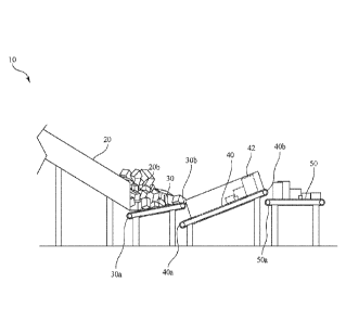
FIG. 1 is a side view of an exemplary system for managing parcel flow made in
accordance with the present invention, with a bulk flow of parcels from an
upstream conveyor
offloaded onto a damming conveyor of the system;
FIG. 2 is another side view of the exemplary system of FIG. 1, but, as
compared to FIG.
1, with additional parcels offloaded from the upstream conveyor onto the
damming conveyor of
the system of FIG. 1;
FIG. 3 is another side view of the exemplary system of FIG. 1, but, as
compared to FIG.
2, with some parcels offloaded from the damming conveyor onto a destacking
conveyor of the
system of FIG. 1;
FIG. 4 is another side view of the exemplary system of FIG. 1, but, as
compared to FIG.
3, with some parcels offloaded from the destacking conveyor onto a downstream
conveyor, and
with additional parcels offloaded from the upstream conveyor onto the damming
conveyor of the
system of FIG. 1;
FIG. 5 is a schematic diagram of a control subsystem for regulating operation
of the
system of FIG. 1;
FIG. 6 is a side view of another exemplary system for managing parcel flow
made in
accordance with the present invention;
4
CA 03169062 2022-08-09
WO 2021/173195
PCT/US2020/059650
FIG. 7 is a schematic diagram of a control subsystem for regulating operation
of the
system of FIG. 6;
FIG. 8 is a side view of another exemplary system for managing parcel flow
made in
accordance with the present invention; and
FIG. 9 is a schematic diagram of a control subsystem for regulating operation
of the
system of FIG. 8.
DETAILED DESCRIPTION OF THE INVENTION
The present invention is a system for managing parcel flow, which includes a
damming
conveyor for regulating downstream parcel distribution.
FIG. 1 is a side view of an exemplary system 10 for managing parcel flow made
in
accordance with the present invention. As shown in FIG. 1, the exemplary
system 10 includes:
an upstream conveyor 20 for receiving and conveying a bulk flow of parcels;
and a damming
conveyor 30 having a proximal end 30a positioned to receive parcels offloaded
from a distal end
20b of the upstream conveyor 20. The exemplary system 10 also includes: a
destacking conveyor
40 having a proximal end 40a positioned to receive parcels offloaded from a
distal end 30b of the
damming conveyor 30; and a downstream conveyor 50 having a proximal end 50a
positioned to
receive parcels offloaded from a distal end 40b of the destacking conveyor 40.
As further
described below, the damming conveyor 30 can be selectively activated and
deactivated (or
"indexed") to regulate the initial offloading of parcels from the distal end
20b of the upstream
conveyor 20 onto the damming conveyor 30 and subsequent offloading of parcels
from the
damming conveyor 30 onto the destacking conveyor 40. In this regard, indexing
of the damming
conveyor 30 thus helps to feed the destacking conveyor 40 with a discrete
amount of parcels,
5
CA 03169062 2022-08-09
WO 2021/173195
PCT/US2020/059650
instead of a continuous flow which may potentially overwhelm the destacking
conveyor 40 and
prevent effective operation thereof
Referring still to FIG. 1, the destacking conveyor 40 is oriented at a
predetermined angle
to separate parcels which are vertically stacked prior to being offloaded onto
the downstream
conveyor 50. In some embodiments, the destacking conveyor 40 may also be
selectively
activated and deactivated to regulate the offloading of parcels onto the
downstream conveyor 50.
As further described below with reference to FIGS. 5, 7, and 9, in some
embodiments,
activation and deactivation of the damming conveyor 30 and/or the destacking
conveyor 40 may
be regulated based on instructions communicated from a control subsystem 70,
170, 270.
Referring still to FIG. 1, as indicated above, the upstream conveyor 20 is
configured to
receive and subsequently convey a bulk flow of parcels to the damming conveyor
30, and thus
can be any conveying device suitable for doing so, including, for example, a
belt conveyor, roller
conveyor, etc. In this exemplary embodiment, the upstream conveyor 20 is a
chute, which
defines an inclined pathway along which a bulk flow of parcels can slide
downward (under the
force of gravity) toward the proximal end 30a of the damming conveyor 30. In
this regard, the
upstream conveyor 20 is thus oriented at a predetermined angle, cii, relative
to the underlying
ground surface on which it is positioned.
FIGS. 2-4 are various side views of the system 10 of FIG. 1, which illustrate
movement
of parcels through the system 10, from the upstream conveyor (or chute) 20 to
the downstream
conveyor 50.
Referring now to FIGS. 1-4, in operation, the proximal end 30a of damming
conveyor 30
receives parcels offloaded from the distal end 20b of the upstream conveyor
20. When activated,
the damming conveyor 30 then conveys parcels along its length, from the
proximal end 30a to
6
CA 03169062 2022-08-09
WO 2021/173195
PCT/US2020/059650
the distal end 30b, for eventual offloading onto the destacking conveyor 40
(or other downstream
conveyor). When deactivated, however, movement of parcels along the length of
the damming
conveyor 30 is ceased, thus permitting a buildup of parcels offloaded from the
upstream
conveyor 20 near the proximal end 30a of the damming conveyor 30. Such buildup
eventually
creates a "dam" against a backpressure caused by the bulk flow of parcels
traveling down the
upstream conveyor 20, which effectively limits the volume of parcels offloaded
from the
upstream conveyor 20 onto the damming conveyor 30. In this way, the damming
conveyor 30
can be deactivated to permit an accumulation of parcels to a desired batch
size and subsequently
activated to offload the parcels within the batch in a controlled manner to
the destacking
conveyor 40.
Referring now to FIGS. 1 and 2, as mentioned above, the damming conveyor 30 is
selectively activated and deactivated to transfer parcels along its length,
from the proximal end
30a to the distal end 30b, which are then offloaded to the destacking conveyor
40 (or other
downstream conveyor). In this exemplary embodiment, the damming conveyor 30 is
selectively
activated and deactivated in accordance in a prearranged (pre-programmed)
sequence
corresponding to periods of time where the damming conveyor 30 is activated
and periods of
time where the damming conveyor 30 is deactivated to intermittently offload
parcels to the
destacking conveyor 40 in a controlled manner (i.e., in batches) and to
provide the above-
described "damming" action at the distal end 20b of the upstream conveyor 20.
Referring still to FIGS. 1 and 2, as an intermediate structure between the
upstream
conveyor 20 and the destacking conveyor 40, with parcels transferred in
batches along its length,
from its proximal end 30a to the distal end 30b, the damming conveyor 30 helps
to ensure the
destacking conveyor 40 is able to function properly. In other words, without
the damming
7
CA 03169062 2022-08-09
WO 2021/173195
PCT/US2020/059650
conveyor 30 regulating parcel flow from the upstream conveyor 20 to the
destacking conveyor
40 (e.g., if parcels were directly offloaded from the upstream conveyor 20
onto the destacking
conveyor 40), the volume of parcels could, in many instances, overwhelm the
destacking
conveyor 40 and prevent the destacking conveyor 40 from effectively separating
vertically
stacked parcels, thereby negatively affecting subsequent downstream sorting.
FIG. 5 is a schematic diagram of a control subsystem 70 for regulating
operation of the
exemplary system 10, and, more particularly, the operation of the damming
conveyor 30 and the
destacking conveyor 40. In this exemplary embodiment, the control subsystem 70
is comprised
of a controller 72, such as a programmable logic controller (PLC), that
communicates
.. instructions to the damming conveyor 30, which causes the damming conveyor
30 to be
activated and deactivated in accordance with the prearranged (pre-programmed)
sequence. To
this end, the controller 72 includes a processor 74 for executing instructions
(routines) stored in a
memory component 76 or other computer-readable medium. Accordingly, in this
exemplary
embodiment, the instructions stored in the memory component 76 effectively
embody the
prearranged sequence corresponding to activation and deactivation of the
damming conveyor 30,
and, thus, can be modified as needed to provide a different prearranged
sequence for activation
and deactivation of the damming conveyor 30 to accommodate different sorting
applications and
environments.
Furthermore, in this exemplary embodiment, the damming conveyor 30 is a motor-
driven
belt conveyor, where the motor of the damming conveyor 30 is operably
connected to the
processor 74 of the controller 72 of the control subsystem 70. Of course, the
damming conveyor
could be another conveying device (e.g., a motor-driven roller conveyor)
suitable for
8
CA 03169062 2022-08-09
WO 2021/173195
PCT/US2020/059650
transferring parcels to the destacking conveyor 40 in a controlled manner
without changing the
operating principles of the system 10.
Referring again to FIGS. 1-4, in this exemplary embodiment, the damming
conveyor 30
is oriented at a predetermined angle, az, relative to the underlying ground
surface on which it is
positioned (as shown in FIG. 1). In FIGS. 1-4, in the exemplary embodiment
illustrated, the
damming conveyor 30 is oriented at an angle, cu, of approximately 10 relative
to the underlying
ground surface. However, in other embodiments, the damming conveyor 30 may be
oriented at
an angle, az, in the range of 10-20 relative to the underlying ground
surface. In this regard, the
optimal angle is, at least in part, dependent on the coefficient of friction
between the parcels and
the belt of the damming conveyor 30. For a typical mix of rigid cardboard
boxes and flexible
plastic ("poly") bags common within sorting facilities, which are being
conveyed by a rubber
belt of the damming conveyor 30, the range of 10-20 is believed to be optimal
and prevents
parcels from falling off of the damming conveyor 30 or sliding back down.
However, other
angles may be more appropriate if the parcel mix was changed and/or a
different fol in of belt
was utilized to convey the parcels.
Referring still to FIGS. 1-4, as the upstream conveyor 20 is in a declining
orientation
(with its proximal end at a higher elevation than its distal end), while the
damming conveyor 30
is in an inclining orientation (with its proximal end 30a at a lower elevation
than its distal end
30b). The upstream conveyor 20 and the damming conveyor 30 thus collectively
define a valley
in which parcels can accumulate and provide the above-described "damming"
action, as perhaps
best shown in FIGS. 2 and 4.
Referring still to FIGS. 1-4, parcels offloaded from the distal end 30b of the
damming
conveyor 30 are received on the proximal end 40a of the destacking conveyor
40. To facilitate
9
CA 03169062 2022-08-09
WO 2021/173195
PCT/US2020/059650
separation of parcels as they are offloaded from the damming conveyor 30, the
proximal end 40a
of the destacking conveyor 40 is preferably positioned at a predetermined
distance, di, below the
distal end 30b of the damming conveyor 30 (as shown in FIG. 1), so that
parcels effectively
tumble off of the distal end 30b of the damming conveyor 30. Furthermore, to
this end, the
destacking conveyor 40 is also oriented at a predetermined angle, a3, relative
to the underlying
ground surface on which the destacking conveyor 40 is positioned (as shown in
FIG. 1).
Specifically, in this exemplary embodiment, the destacking conveyor 40 is
oriented at an angle,
a3, of approximately 20 relative to the underlying ground surface, which is
believed to be
optimal for separating vertically stacked parcels in a mix of rigid cardboard
boxes and flexible
plastic ("poly") bags common within sorting facilities without having such
parcels also slide
down toward the proximal end 40a of the destacking conveyor 40 when conveyed
thereon. Of
course, the angle at which the destacking conveyor 40 is oriented may be
adjusted to
accommodate other parcel mixes. Moreover, to prevent sliding, it is generally
preferred that the
conveying surface of the destacking conveyor 40 be a high-friction surface. To
prevent parcels
from falling off of the destacking conveyor 40 as they are transitioned from a
stacked
configuration to an unstacked configuration, in this embodiment, the
destacking conveyor 40 is
provided with a pair of opposing sidewalls 42 (only one of which is shown)
substantially
extending the length of destacking conveyor 40.
As best shown in FIGS. 3-4, when activated, the destacking conveyor 40 conveys
parcels
along its length, from the proximal end 40a to the distal end 40b, for
eventual offloading onto the
downstream conveyor 50. Conversely, when deactivated, movement of the parcels
along the
length of the destacking conveyor 40 is ceased. Like the damming conveyor 30,
the destacking
conveyor 40 may also be selectively activated and deactivated according to a
prearranged (pre-
CA 03169062 2022-08-09
WO 2021/173195
PCT/US2020/059650
programmed) sequence, as embodied within instructions (routines) stored in the
memory
component 76 or other computer-readable medium, to regulate the volume of
parcels offloaded
from the destacking conveyor 40 onto the downstream conveyor 50 at a given
time.
Furthermore, in this exemplary embodiment, the destacking conveyor 40 is a
motor-
driven belt conveyor, where the motor of the destacking conveyor 40 is
operably connected to
the processor 74 of the controller 72 of the control subsystem 70. Of course,
the destacking
conveyor 40 could be another conveying device (e.g., a motor-driven roller
conveyor) suitable
for offloading parcels to the downstream conveyor 50 in a controlled manner
without changing
the operating principles of the system 10. Although it is generally preferred
that the destacking
conveyor 40 convey parcels in an indexed manner, alternative embodiments are,
however,
contemplated wherein the destacking conveyor 40 remains in an activated
configuration (i.e.,
continuously conveying parcels received thereon) during operation of the
system 10.
Referring still to FIGS. 1-4, parcels offloaded from the distal end 40b of the
destacking
conveyor 40 are received on a proximal end 50a of the downstream conveyor 50.
To ensure
.. parcels are fully offloaded from the distal end 40b of the destacking
conveyor 40 and to further
promote separation of parcels, in this exemplary embodiment, a proximal end
50a of the
downstream conveyor 50 is positioned at a predetermined distance, d2, below
the distal end 40b
of the destacking conveyor 40 (as shown in FIG. 1). In this embodiment, the
downstream
conveyor 50 is a belt conveyor. However, the specific construction of the
downstream conveyor
50 is not particularly germane to the inventive subject matter of the system,
and, as such, may be
any suitable device or receptacle for receiving parcels offloaded from the
destacking conveyor
40. In some implementations, the downstream conveyor 50 may be an input into a
singulation
station, where a robot singulator (or robot) engages each parcel, and then
places it onto an
11
= 4' 7:
induction conveyor, as is described in U.S. Patent No. 10,646,898.
FIG. 6 is a side view of another exemplary system 100 for managing parcel flow
made in
accordance with the present invention. In this exemplary embodiment, the
system 100 again
includes an upstream conveyor 20, damming conveyor 30, destacking conveyor 40,
and
downstream conveyor 50. In other words, these components are identical to
those described above
with reference to FIGS. 1-5. In this regard, like components are provided with
the same reference
numeral throughout the present application. In this exemplary embodiment,
however, instead of the
damming conveyor 30 and the destacking conveyor 40 being activated and
deactivated in accordance in a prearranged sequence, such components are
activated and
deactivated based on data received from one or more sensors 162, 164, 166, 168
corresponding to the
positioning parcels within the system 100. In this exemplary embodiment, four
sensors 162, 164,
166, 168 are used: a damming conveyor sensor 162, a first destacking conveyor
sensor 164, a second
destacking conveyor sensor 166, and a downstream conveyor sensor 168.
Referring still to FIG. 6, the damming conveyor sensor 162 is configured to
detect the
presence of parcels on the damming conveyor 30. Specifically, in this
embodiment, the damming
conveyor sensor 162 is positioned to detect the presence of parcels at the
distal end 30b of the
damming conveyor 30 prior to subsequent offloading onto the destacking
conveyor 40. The first
destacking conveyor sensor 164 is configured to detect the presence of parcels
at a first location
along the length of the destacking conveyor 40. In this embodiment, the first
destacking
conveyor sensor 164 is positioned between the proximal end 40a and the distal
end 40b of the
destacking conveyor 40 to confirm that parcels have been successfully
offloaded from the
damming conveyor 30 and are proceeding to the distal end 40b of the destacking
conveyor 40.
12
CA 3169062 2022-09-27
CA 03169062 2022-08-09
WO 2021/173195
PCT/US2020/059650
The second destacking conveyor sensor 166 is configured to detect the presence
of parcels at a
second location along the length of the destacking conveyor 40. In this
embodiment, the second
destacking conveyor sensor 166 is positioned at the distal end 40b of the
destacking conveyor 40
to detect the presence of parcels on the destacking conveyor 40 prior to
subsequent offloading
onto the downstream conveyor 50. The downstream conveyor sensor 168 is
configured to detect
the presence of parcels on the downstream conveyor 50 to confirm parcels have
been
successfully offloaded from the destacking conveyor 40.
Referring still to FIG. 6, in this exemplary embodiment, the damming conveyor
sensor
162, the first destacking conveyor sensor 164, and the second destacking
conveyor sensor 166
each comprise a photoelectric eye (or photoelectric sensor) configured to emit
a beam of
electromagnetic radiation to detect the presence or absence of parcels at the
location within the
system 100 where such sensors are positioned. In this regard, the data
acquired by the damming
conveyor sensor 162, the first destacking conveyor sensor 164, and the second
destacking
conveyor sensor 166 may be in the form of a binary value, with a first value
(e.g., 0) indicating
no parcels are positioned at the location where the sensor is located, and a
second value (e.g., 1)
indicating that parcels are positioned at the location where the sensor is
located. In this
exemplary embodiment, the downstream conveyor sensor 168 comprises one or more
cameras,
where each camera is configured to acquire two-dimensional and/or three-
dimensional image
data. In this regard, the one or more cameras of the downstream conveyor
sensor 168 are
positioned to acquire images of the downstream conveyor 50 and parcels
offloaded thereon.
FIG. 7 is a schematic diagram of a control subsystem 170 for regulating
operation of the
damming conveyor 30 and destacking conveyor 40 of the system 100. In this
exemplary
embodiment, the instructions communicated by the control subsystem 170 to the
damming
13
CA 03169062 2022-08-09
WO 2021/173195
PCT/US2020/059650
conveyor 30 and destacking conveyor 40 are informed by data from the damming
conveyor
sensor 162, the first destacking conveyor sensor 164, the second destacking
conveyor sensor 166,
and the downstream conveyor sensor 168.
Referring still to FIG. 7, the control subsystem 170 includes a controller
172, such as a
programmable logic controller (PLC), that communicates instructions to the
damming conveyor
30 and to the destacking conveyor 40, which cause each of the damming conveyor
30 and the
destacking conveyor 40 to be activated and deactivated based on data received
from the
damming conveyor sensor 162, the first destacking conveyor sensor 164, the
second destacking
conveyor sensor 166, and the downstream conveyor sensor 168. To this end, the
damming
conveyor sensor 162, the first destacking conveyor sensor 164, the second
destacking conveyor
sensor 166, and the downstream conveyor sensor 168 are each operably connected
to the
controller 172, such that data collected by the sensors is transmitted to the
controller 172 for
subsequent processing. The controller 172 includes a processor 174 for
executing instructions
(routines) stored in a memory component 176 or other computer-readable medium.
The
.. controller 172 analyzes the data received from the damming conveyor sensor
162, the first
destacking conveyor sensor 164, the second destacking conveyor sensor 166, and
the
downstream conveyor sensor 168, and then communicates instructions to
selectively activate and
deactivate the damming conveyor 30 and the destacking conveyor 40 based on the
positioning of
parcels within the system 100.
Referring now to FIGS. 6 and 7, in some embodiments, when the system 100 is
initially
started or the downstream conveyor sensor 168 communicates data to the
controller 172
indicating that it does not detect the presence of parcels on the downstream
conveyor 50, the
controller 172 communicates instructions which causes (i) the damming conveyor
30 to run (i.e.,
14
CA 03169062 2022-08-09
WO 2021/173195
PCT/US2020/059650
convey parcels) until the damming conveyor sensor 162 detects the presence of
a parcel, and (ii)
the destacking conveyor 40 to run until the first destacking conveyor sensor
164 and the second
destacking conveyor sensor 166 each detect the presence of a parcel. Following
such sequence,
the controller 172 may then communicate instructions which cause the
destacking conveyor 40
to run a predetermined (jog) distance to offload any parcels located near the
distal end 40b of the
destacking conveyor 40 onto the downstream conveyor 50. To avoid overwhelming
the
downstream conveyor 50 and/or a robot singulator picking parcels therefrom,
the destacking
conveyor 40 preferably remains deactivated until the downstream conveyor
sensor 168
communicates data to the controller 172 indicating that no parcels are
detected on the
downstream conveyor 50. Upon determining that all parcels have been removed
from the
downstream conveyor 50, the controller 172 then communicate instructions which
cause the
damming conveyor 30 and the destacking conveyor 40 to again run until the
presence of a parcel
is detected by each of the damming conveyor sensor 162, the first destacking
conveyor sensor
164, and the second destacking conveyor sensor 166.
Referring still to FIGS. 6 and 7, for efficiency, it is generally preferred
that, each time
one or more parcels are offloaded from the destacking conveyor 40 onto the
downstream
conveyor 50, the damming conveyor 30 and the destacking conveyor are indexed,
such that a
parcel is positioned at each of the distal end 30b of the damming conveyor 30,
the proximal end
40a of the destacking conveyor 40, and the distal end 40b of the destacking
conveyor 40, as
shown in FIG. 6. In such a configuration, the parcels are effectively in queue
for subsequent
conveyance downstream and eventual offloading onto the downstream conveyor 50
in a manner
which helps to reduce wait times between successive parcel deposits onto the
downstream
conveyor 50. To this end, in instances where neither the second destacking
conveyor sensor 166
CA 03169062 2022-08-09
WO 2021/173195
PCT/US2020/059650
nor the downstream conveyor sensor 168 detect the presence of parcels, the
controller 172 may
be configured to communicate instructions which cause the destacking conveyor
40 to
continuously run until the second destacking conveyor sensor 166 detects the
presence of a
parcel. Moreover, in instances where the damming conveyor sensor 162 detects
the presence of a
parcel and the first destacking conveyor sensor 164 does not, the controller
172 may be
configured to communicate instructions which cause the damming conveyor 30 to
run a
predetermined (jog) distance until the first destacking conveyor sensor 164
detects the presence
of a parcel. Furthermore, in instances where the first destacking conveyor
sensor 164 detects the
presence of a parcel, but the damming conveyor sensor 162 does not, the
controller 172 may be
configured to communicate instructions which cause the damming conveyor 30 to
continuously
run until both the damming conveyor sensor 162 and the first destacking
conveyor sensor 164
detect the presence of a parcel. Of course, it should be appreciated that the
controller 172 may be
configured to communicate additional or alternative instructions to the
damming conveyor 30
and/or the destacking conveyor 40 based on various data communicated from the
damming
conveyor sensor 162, the first destacking conveyor sensor 164, the second
destacking conveyor
sensor 166, and the downstream conveyor sensor 168 to accommodate different
sorting
applications or parcel volumes without departing from the spirit or scope of
the present
invention.
FIG. 8 is a side view of another exemplary system 200 for managing parcel flow
made in
accordance with the present invention. In this exemplary embodiment, the
system 200 again
includes an upstream conveyor 20, damming conveyor 30, destacking conveyor 40,
and
downstream conveyor 50. In other words, these components are identical to
those described
above with reference to FIGS. 1-5 and 6-7. Again, like components are provided
with the same
16
CA 03169062 2022-08-09
WO 2021/173195
PCT/US2020/059650
reference numeral throughout the present application. In this exemplary
embodiment, however,
instead of the damming conveyor 30 and the destacking conveyor 40 being
activated and
deactivated in accordance in a prearranged sequence or based on data from
multiple sensors
distributed at various locations throughout the system, the damming conveyor
30 is indexed in
response to data received from a single destacking conveyor sensor 260
configured to detect the
presence of parcels on the destacking conveyor 40. More specifically, in this
embodiment, the
destacking conveyor sensor 260 is a camera configured to acquire two-
dimensional and/or three-
dimensional image data of parcels along at least a portion of a length, 1, of
the destacking
conveyor 40.
FIG. 9 is a schematic diagram of a control subsystem 270 for regulating
operation of the
damming conveyor 30 of the system 200. In this exemplary embodiment, the
instructions
communicated by the control subsystem 270 to the damming conveyor 30 are
informed by data
from the destacking conveyor sensor 260.
Referring still to FIG. 9, the control subsystem 170 includes a controller
272, such as a
programmable logic controller (PLC), that communicates instructions to the
damming conveyor
30, which cause the damming conveyor 30 to be activated and deactivated based
on data
received from the destacking conveyor sensor 260. To this end, the destacking
conveyor sensor
260 is operably connected to the controller 272, such that data collected by
the destacking
conveyor sensor 260 is transmitted to the controller 272 for subsequent
processing. The
controller 272 includes a processor 274 for executing instructions (routines)
stored in a memory
component 276 or other computer-readable medium. The controller 272 analyzes
the data
received from the destacking conveyor sensor 260 and communicates instructions
to selectively
17
CA 03169062 2022-08-09
WO 2021/173195
PCT/US2020/059650
activate and deactivate the damming conveyor 30 based on the positioning of
parcels on the
destacking conveyor 40.
Referring now to FIGS. 8 and 9, in this exemplary embodiment, the controller
272
selectively activates and deactivates the damming conveyor 30 based on the
positioning of
parcels relative to predetermined boundaries (illustrated in dashed vertical
lines) set along the
length, 1, of the destacking conveyor 40. In this regard, the controller 272
sets a first boundary,
bi, corresponding to a first distance, d3, from the proximal end 40a of the
destacking conveyor 40
and a second boundary, b2, corresponding to a second distance, d4, from the
proximal end 40a of
the destacking conveyor 40. The controller 272 determines the positioning of
parcels on the
destacking conveyor 40 relative to the first boundary, bi, and the second
boundary, b2, based on
data received from the destacking conveyor sensor 260. The controller 272 then
communicates
instructions to the damming conveyor 30 based on that determination.
Specifically, when the
controller 272 receives data from the destacking conveyor sensor 260
indicating that no parcels
are present between the proximal end 40a of the destacking conveyor 40 and the
first boundary,
bi, the controller 272 communicates instructions which cause the damming
conveyor 30 to run
until parcels are detected at the second boundary, b2. The damming conveyor 30
will then remain
at rest until the controller 272 receives data from the destacking conveyor
sensor 260 indicating
that no parcels are present between the proximal end 40a of the destacking
conveyor 40 and the
first boundary, bi, at which time the foregoing process is repeated. Of
course, it should be
appreciated that the controller 272 can be configured to communicate
additional or alternative
instructions to the damming conveyor 30 based on the parcels location relative
to the first
boundary, bi, and the second boundary, b2, to accommodate different sorting
applications or
parcel volumes without departing from the spirit or scope of the present
invention.
18
CA 03169062 2022-08-09
WO 2021/173195
PCT/US2020/059650
In the exemplary embodiment described above with respect to FIGS. 6-7, the
destacking
conveyor 40 is configured to continuously run; however, it is contemplated
that, in alternative
embodiments, the destacking conveyor 40 of the system 200 may also be
selectively activated
and deactivated based on instructions from the control subsystem 270.
Accordingly, in some
embodiments of the system 200, the destacking conveyor 40 may also be operably
connected to
the control subsystem 270.
Although the present invention is described primarily in the context of
processing parcels
within a sorting facility, it is appreciated that the present invention may be
utilized in alternative
applications or environments in which objects need to be conveyed downstream
in a controlled
manner.
One of ordinary skill in the art will recognize that additional embodiments
and
implementations are also possible without departing from the teachings of the
present invention.
This detailed description, and particularly the specific details of the
exemplary embodiments and
implementations disclosed therein, is given primarily for clarity of
understanding, and no
unnecessary limitations are to be understood therefrom, for modifications will
become obvious
to those skilled in the art upon reading this disclosure and may be made
without departing from
the spirit or scope of the invention.
19