Note: Descriptions are shown in the official language in which they were submitted.
CA 03169157 2022-07-15
WO 2021/146547
PCT/US2021/013619
RAPIDLY COOLING FOOD AND DRINKS
CROSS-REFERENCE TO RELATED APPLICATIONS
[0001] This application claims priority to U.S. Provisional Patent Application
No.
62/961,495, filed on January 15, 2020. The entire content of this application
is
incorporated herein by reference.
TECHNICAL FIELD
[0002] This disclosure relates to systems and methods for rapidly cooling food
and drinks.
BACKGROUND
[0003] Beverage brewing system have been developed that rapidly prepare single
servings of hot beverages. Some of these brewing systems rely on single use
pods to
which water is added before brewing occurs. The pods can be used to prepare
hot coffees,
teas, and cocoas.
[0004] Home use ice cream makers can be used to make larger batches (e.g., 1.5
quarts or more) of ice cream for personal consumption. These ice cream maker
appliances typically prepare the mixture by employing a hand-crank method or
by
employing an electric motor that is used, in turn, to assist in churning the
ingredients
within the appliance. The resulting preparation is often chilled using a pre-
cooled vessel
that is inserted into the machine. Some electric ice cream machines take 20 to
60 minutes
to make a batch of ice cream and require time consuming clean up.
SUMMARY
[0005] This specification describes systems and methods for rapidly cooling
food
and drinks. Some of these systems and methods can cool food and drinks in a
container
inserted into a counter-top or installed machine from room temperature to
freezing in less
than two minutes. For example, the approach described in this specification
has
successfully demonstrated the ability make soft-serve ice cream from room-
temperature
1
Date Recue/Date Received 2022-07-15
CA 03169157 2022-07-15
WO 2021/146547
PCT/US2021/013619
pods in approximately 90 seconds. This approach has also been used to chill
cocktails
and other drinks including to produce frozen drinks. These systems and methods
are
based on a refrigeration cycle with low startup times and a pod-machine
interface that is
easy to use and provides extremely efficient heat transfer.
[0006] Some of the pods described are filled with ingredients in a
manufacturing
line and subjected to a sterilization process (e.g., retort, aseptic
packaging, ultra-high
temperature processing (UHT), ultra-heat treatment, ultra-pasteurization, or
high pressure
processing (HPP)). HPP is a cold pasteurization technique by which products,
already
sealed in its final package, are introduced into a vessel and subjected to a
high level of
isostatic pressure (300-600 megapascals (MPa) (43,500 ¨ 87,000 pounds per
square inch
(psi)) transmitted by water. The pods can be used to store ingredients
including, for
example, dairy products at room temperature for long periods of time (e.g., 9-
12 months)
following sterilization.
[0007] Ice cream is considered a low acid food with pH levels ranging between
5.0 and 8Ø The acidity of ice cream is shown in the table below in relation
to other
food. The table shows a range of pH levels along a horizontal axis ranging
from high
alkaline content foods on the left, to high acid content foods on the right.
Ice cream is a
low acid food within the eggs and dairy food category. More specifically, a
low-acid
food is a food with a finished equilibrium pH greater than 4.6 and a water
activity greater
than 0.85.
2
Date Recue/Date Received 2022-07-15
CA 03169157 2022-07-15
WO 2021/146547
PCT/US2021/013619
Food High Alkaline Low Low Acid Acid High
Category Alkaline Alkaline Acid
Grains, Amaranth, Rye White Rice,
Cereals Lentils, Bread, White
Sweetcom, Whole Bread,
Wild Rice, Grain Pastries,
Quinoa, Bread, Biscuits,
Millet, Oats, Pasta
Buckwheat Brown
Rice
Meat Liver, Fish, Beef,
Oysters, Turkey, Pork,
Organ Chicken, Veal,
Meat Lamb Shellfish,
Canned
Tuna &
Sardines
Eggs & Breast Soy Whole Eggs, Parmesan,
Dairy Milk Cheese, Milk, Camembert, Processed
Soy Milk, Butter, Hard Cheese
Goat Milk, Yogurt, Cheese
Goat Cottage
Cheese, Cheese,
Buttermilk, Cream,
Whey Ice Cream
Nuts * Hazelnuts, Chestnuts, Pumpkin, Pecans, Peanuts,
Seeds Almonds Brazils, Sesame, Cashews, Walnuts
Coconut Sunflower Pistachios
Seeds
Oils Flax Seed Corn Oil,
Oil, Olive Sunflower
Oil Oil,
Margarine
[0008] Figure 1 is a process diagram for one approach to manufacturing ice
cream. In this approach, the raw material undergoes homogenization,
pasteurization,
crystallization, quick freezing, packaging, and storage.
[0009] Pasteurization is a process in which food (e.g., dairy or milk) is
treated
with mild heat, usually to less than 100 C (212 F), to eliminate pathogens
and extend
shelf life. The process is intended to destroy or deactivate organisms and
enzymes that
contribute to spoilage or risk of disease, including vegetative bacteria, but
not bacterial
3
Date Recue/Date Received 2022-07-15
CA 03169157 2022-07-15
WO 2021/146547
PCT/US2021/013619
spores. Pasteurization is not sterilization and may not kill bacterial spores.
Pasteurization reduces the number of organisms in food.
[0010] The shelf life of refrigerated pasteurized dairy is usually greater
than that
of milk. For example, high-temperature, short-time (HTST) pasteurized milk
typically
has a refrigerated shelf life of two to three weeks, whereas ultra-pasteurized
milk can last
much longer, sometimes two to three months. When ultra-heat treatment (UHT) is
combined with sterile handling and container technology (such as retort or
aseptic
packaging as previously described), the dairy can even be stored non-
refrigerated for
much longer periods of time, e.g., 9-12 months.
[0011] However, during ultra-heat treatment combined with retort-based sterile
handling and container technology, pasteurized dairy can caramelize and become
brown
which can be undesirable. The highest rate of browning, or more generally
referred to as
color development, can be caused by the presence of fructose which begins to
caramelize
at temperatures of 230 F. Caramelization should not be confused with the
Maillard
reaction, in which reducing sugar reacts with amino acids. The process of
browning, or
the Maillard reaction, creates flavor and changes the color of food. Maillard
reactions
generally begin to occur at temperatures above 285 F. For example,
caramelization
temperatures of fructose can be 230 F, galactose can be 320 F, glucose can be
320 F,
lactose can be 397 F, and sucrose can be 320 F.
[0012] While the pasteurization process extends shelf life, there can also be
a
need for homogenization. Homogenization is typically done either before or
after
pasteurization but before the freezing of the liquid ice cream mix.
Homogenization is a
commonly performed for any ice cream mix containing fat or oil and is
traditionally used
in the production of dairy products such as milk, yogurt, ice cream, and
beverages such as
juice, soy milk, and peanut milk. Homogenization not only creates a uniform
mix, but
also reduces the size of the fat droplets, resulting in a stabilized emulsion.
It results in a
greater viscosity and in the production of a more uniform color. It gives ice
cream its
creamy texture by breaking down large fat globules.
[0013] The process of homogenization occurs in the homogenizer, which works
like a piston pump by drawing in air and then forcing it out at a very high
pressure. This
4
Date Recue/Date Received 2022-07-15
CA 03169157 2022-07-15
WO 2021/146547
PCT/US2021/013619
pressure is used to force the liquid ice cream through a very small tube-like
opening,
creating very fine fat particles that prevent the separation of cream. The
pressure
depends on the fat and solids in the liquid ice cream mix. Lower pressures can
be used
when high fat and total solids are included in the liquid ice cream mix. If a
two stage
homogenizer is used, a pressure of 2000-2500 psi on the first stage and 500-
1000 psi on
the second stage are satisfactory under most conditions, however for low-fat
ice creams
the pressure can be higher (e.g., 2,900 psi).. Two stage homogenization is
preferred for
ice cream mix. Clumping or clustering of the fat is reduced by producing a
thinner, more
rapidly whipped ice cream mix.
[0014] The high pressure of the homogenization process creates a more stable
emulsion and smaller fat particles. The smaller the fat particles, the more
surface area is
obtained. This results in more fat networks that will stabilize more air,
which in turn
slows down ice re-crystallization. For high-fat ice cream, the homogenization
pressure is
lower. Especially for an ice cream mix of more than 13% fat, it is preferable
to reduce the
pressure to minimize the risk of cluster formation. In addition, this process
effectively
mixes all the ingredients, avoids disintegration of any soft materials and
prevents the
growth of harmful bacteria. Homogenization is important in the ice cream
production
process, since it determines the reaction of the ice cream mix when it is
frozen, hardened
and distributed. Homogenization of the ice cream mix gives the ice cream a
smoother
texture, gives the ice cream greater apparent richness and palatability, give
the ice cream
better air stability and increases the ice cream's resistance to melting.
[0015] Low-acid foods packaged in hermetically sealed containers are defined
as
low-acid-canned-foods ("LACF") and are regulated by Title 21, Code of Federal
Regulations (21 CFR) part 113. A hermetically sealed container is a container
that is
designed and intended to be secure against the entry of microorganisms and
thereby to
maintain the commercial sterility of its contents after processing. Low-acid-
canned-
foods are defined by being (i) shelf stable, (ii) heat-treated, (iii) having a
pH of >4.6, and
(iv) having a water activity of 0.85.
[0016] Once packaged, the low-acid-canned-food is sterilized. The method of
sterilization is a thermal based process, or the application of high heat to
the product.
Date Recue/Date Received 2022-07-15
CA 03169157 2022-07-15
WO 2021/146547
PCT/US2021/013619
The high temperatures required in a sterilization process destroys pathogenic
organisms
that may be present in/on the container and/or food product, and is well above
the boiling
point of water at normal atmospheric pressure. Sterilization kills or
deactivates living
organism in the food product. Thermal processing/sterilization of shelf
stable, low acid
foods is usually performed at temperatures at or above about 250 F. The higher
the
temperature, the shorter the time the product needs to be exposed to heat.
[0017] There are two primary methods for sterilizing low-acid-canned-foods
such
as ice cream. The first method is a retort process, sometimes also called an
autoclave or
sterilizer, which is a pressure vessel used in the food manufacturing industry
to sterilize
or "commercially sterilize" food after it has been placed into its container
and the
container has been hermetically sealed. A report process or "retort" machine
can be
static or agitating style machines. Agitating style retort machines are
typically used for
convective (e.g., "flowable liquid") type products, such as liquid ice cream,
that benefits
from some product movement (e.g., "stirring") in the container during the
process. These
benefits can either be from a process stand-point (e.g., to improve the rate
of heat transfer
into/out of the container), and/or from a product quality stand-point (e.g.,
to shorten the
exposure time to heat). Agitating style retorts can utilize various methods of
agitation
depending on the orientation of the product container. Vertically oriented
containers,
such as cans, are typically agitated in a rotary fashion, either axially or
end-over-end, but
horizontal agitation can also be used.
[0018] The second process of sterilizing low-acid-canned-foods is aseptic
processing which is a processing technique where commercially thermally
sterilized
liquid products (typically foods such as liquid ice cream) are packaged into
previously
sterilized containers under sterile conditions to produce shelf-stable
products that do not
need refrigeration. Aseptic processing includes aseptic hermetical sealing in
an
atmosphere free of microorganisms. The regulations of 21 CFR 113 include
guidance on
times and temperatures for the sterilization process.
[0019] The best ice creams have a smooth and creamy texture. This creamy
texture, primarily associated with a high fat content, is also determined by
the average
size of the ice crystals. Ice crystal size is governed by the mix formulation,
as well as by
6
Date Recue/Date Received 2022-07-15
CA 03169157 2022-07-15
WO 2021/146547
PCT/US2021/013619
factors relating to the freezing process; residence time; the evaporation
temperature of the
refrigerant fluid; dasher speed; and draw temperature. Each of these factors
is described
in detail below. Although discussed with respect to ice cream, the
relationship between
ice crystals and smoothness is also relevant to other frozen foods and drinks.
[0020] Figure 2A shows a typical relationship between smoothness and ice
crystal
size. In Figure 2A, ice crystal size increases from left to right along the
horizontal axis
while the smoothness increases from bottom to top along the vertical axis.
Typical
values are shown with an approximate linear trend line through the data. The
data and
trend indicates that decreasing ice crystal size (down to micrometer size) is
directly
correlated with increasing smoothness of the ice cream. Ice crystal size can
be measured
in various ways such as using a light microscope. Typically a quantity of ice
cream is
analyzed and an average ice crystal size is measured by the light microscope.
It is
possible to have variations in ice crystal size. Smooth and creamy ice cream
requires the
majority of ice crystals to be small, under 50 gm in size, and preferably 10-
20 gm in size.
If many crystals are larger than this, the ice cream will be perceived as
being coarse or
icy.
[0021] Ice crystals in ice cream range in size from about 1 to over 150 p.m in
diameter, with an average size of about 25 pm. Small ice crystals, around 10
to 20 p.m in
size, give ice cream its smooth and creamy texture, whereas larger ice
crystals, for
example ice crystals greater than 50 pm, impart a grainy texture.
[0022] The growth of the ice crystals can be controlled using stabilizers.
Stabilizers are typically used to increase the melt resistance and shelf life
of ice cream.
Examples of stabilizers are guar gum, carob bean gum and cellulose gum and
limit the
growth of ice crystals by limiting the mobility of water in the unfrozen ice
cream mix.
Stabilizers also limit ice crystal growth by reducing ripening that occurs
during early
stages of hardening and during storage and distribution of the ice cream mix
(e.g., when
the ice cream mix is exposed to relatively high temperatures (e.g. +10 to +18
F)). In
these temperature ranges, a degree of freeze concentration is low, producing
relatively
low viscosity in the unfrozen portion. Low viscosity allows water to migrate
from small
to large ice crystals, which increases the average ice crystal size of the ice
cream.
7
Date Recue/Date Received 2022-07-15
CA 03169157 2022-07-15
WO 2021/146547
PCT/US2021/013619
Stabilizer act to limit this ice crystal growth by increasing the viscosity of
the ice cream
mix. Stabilizers limit water mobility by reducing a ripening effect at a
freeze
concentration. Stabilizers limit the size of air bubbles which grown through a
process of
disproportion.
[0023] The rheological effects of stabilizers are important in stabilizing
properties
of the finished ice cream related to the mobility of water in the unfrozen
system. For
example, high viscosity ice cream limits the temperature at which ice cream
can be
withdrawn and handled from the barrel of the ice cream freezer. When this
happens, the
amount of water frozen in the freezer is reduced. This has an undesirable
effect on the
resistance of the ice cream to heat shock. Low-viscosity stabilizers have not
traditionally
been used in ice cream because of an assumed lack of influence on water
mobility.
[0024] At a point referred to as the "break point," a degree of concentration
can
cause the stabilizer and, possibly, other water-soluble compounds, to interact
with each
other, sometimes irreversibly, thus markedly increasing the effect on water
mobility.
This can be combined with an extreme freeze concentration that occurs at low
frozen
storage temperatures to produce other interactions between individual water-
soluble
compounds.
[0025] In addition to stabilizers, emulsifiers are traditionally added to an
ice
cream mix. Emulsifiers migrate to the interface between the fat and the water
of the ice
cream mix. Emulsifiers attach themselves to the surface of the fat globules
and cause the
protein molecules to displace. Emulsifiers are used to improve the melting
properties
during shipping and storage. Examples of emulsifiers are mono-diglycerides
(E471),
lactic acid esters (E472b), propylene glycol esters (E477) and blends of
these.
[0026] Emulsifiers are used in ice cream because they contribute to smooth and
creamy texture by promoting fat destabilization. Fat destabilization refers to
the process
of clustering and clumping (known as partial coalescence) of the fat in an ice
cream mix
when it is churned in a machine. Because it is the proteins that stabilize the
fat emulsion
in an ice cream mix, emulsifiers are added to ice cream to reduce the
stability of this
emulsion and encourage some of the fat globules to come together, or partially
coalesce.
When a mix is churned in an ice cream machine, air bubbles that are beaten
into the mix
8
Date Recue/Date Received 2022-07-15
CA 03169157 2022-07-15
WO 2021/146547
PCT/US2021/013619
are stabilized by this partially coalesced fat, giving a smooth texture to the
ice cream.
Traditionally, if emulsifiers were not added, the air bubbles would not be
properly
stabilized and the ice cream would not have the same smooth texture.
[0027] Egg yolks are used as both a stabilizer, that thickens the mixture, and
as an
emulsifier, which encourages partial coalescence. To make use of the
emulsifying
properties of egg yolks, approximately 0.5 to 1% of the mixture should be egg
yolk. To
make use the stabilizing (thickening) properties as well, the proportion of
egg yolk is
traditionally increased to 3-4%. However, some frozen custard style ice creams
can
include over 8% of egg yolk.
[0028] Egg yolks include Lecithin which helps to make them good emulsifiers.
In
fact, egg lecithin has emulsification and lubricant properties, and is a
surfactant.
However, Lecithin need not only be extracted from egg yolk. Lecithin can be
extracted
from plant-based sources such as soybeans, sunflowers and rapeseed. Plant-
based
Lecithin can emulsify just as well as egg yolks without egg flavor and extra
fat.
[0029] Many store-bought ice creams include stabilizers and emulsifiers to
help
keep the ice crystals from growing by improving the melting properties during
shipping
and storage and by increasing the shelf life of ice cream. An example is Ben &
Jerry's
Cinnamon Buns ice cream which includes: cream, skim milk, water, liquid sugar,
sugar,
dried cane syrup, wheat flour, corn syrup, egg yolks, brown sugar, soybean
oil, butter,
coconut oil, molasses, salt, cinnamon, soy lecithin, sodium bicarbonate,
spice, vanilla
extract, guar gum, and carrageenan. In this example, the stabilizers include
guar gum and
the emulsifiers include egg yolks, soybean oil, soy lecithin, carrageenan.
[0030] As previously described, ice crystal size is a factor in the
development of
smooth and creamy ice cream. Creamy ice cream requires the majority of ice
crystals to
be small, preferably under 50 pm in size. If many crystals are larger than
this, the ice
cream will be perceived as being coarse.
[0031] Ice cream is frozen in two stages: dynamic and static freezing. Dynamic
freezing is a dynamic process where the mix is frozen in an ice cream machine
while
being agitated to incorporate air, destabilize the fat, and form ice crystals.
The ice cream
mix enters the ice cream machine at a temperature slightly above its freezing
point, i.e.,
9
Date Recue/Date Received 2022-07-15
CA 03169157 2022-07-15
WO 2021/146547
PCT/US2021/013619
the temperature where the water in the mix begins to freeze. The ice cream
machine
cools the mix and brings it below the freezing point of the mix. At this
point, a layer of
ice freezes to the walls of the ice cream machine which causes rapid
nucleation where
small ice crystals begin to form. Upon exiting the ice cream machine, the ice
cream, at
about -5 C to -6 C (23 to 21.2 F) exits with a consistency similar to soft-
serve ice cream.
[0032] The ice cream then undergoes static freezing where it is hardened in a
freezer without agitation until the core of the ice cream reaches a specified
temperature,
usually -18 C (-0.4 F). New ice crystals are formed during static freezing but
the
existing small crystals begin to grow in size until the temperature decreases
to -18 C
(0.4 F), or ideally -25 C to -30 C (-9.4 to -20.2 F), to halt this growth. It
is
advantageous to cool the ice cream as quickly as possible during this process
to limit the
growth of the ice crystals.
[0033] During static freezing, ice crystals typically grow by about 30% to 40%
to
an average size of about 25 to 45 gm. A mean ice crystal size of about 50 gm
is
considered an average point where consumers start to notice a coarse texture.
During
static freezing ice crystals can often grow to over 100 gm Figure 2B shows an
image of
typical ice crystals during this process. The ice crystals in the image of
Figure 2B are of
various shapes and sizes but some ice crystals are over 100 gm in diameter.
[0034] However, the ice cream described in this specification does not require
static freezing because the ice cream is not stored. The ice cream is served
ready for
consumption. By eliminating the static freezing step, growth of ice crystals
(e.g., ice
crystals typically grow by about 30% to 40%) during the static freezing
process is
eliminated.
[0035] The dynamic freezing stage is an important step in creating ice cream
because this is the stage in which crystallization of the ice cream occurs.
During dynamic
freezing, the ice cream mix is added to the ice cream machine at between 0 C
and 4 C
(32 F and 39.2 F). As the refrigerant absorbs the heat in the mix, a layer of
ice freezes to
the wall of the cold barrel wall causing rapid nucleation, that is, the birth
of small ice
crystals.
Date Recue/Date Received 2022-07-15
CA 03169157 2022-07-15
WO 2021/146547
PCT/US2021/013619
[0036] To produce small ice crystals during a dynamic freezing process, a high
rate of nucleation, minimal growth, and minimal recrystallization are desired.
Colder
refrigerant temperatures and slower dasher speeds can promote higher rates of
nucleation.
Shorter residence times, lower dasher speeds, and lower draw temperatures can
to
minimize growth and recrystallization.
[0037] Figure 2C shows a process of a rotating dasher also called a mixer,
impeller, blade, scraper, or paddle, where the rotating dasher is used to
scrape the ice
crystals formed at the cold barrel wall 22. The design and rotation of the
rotating dasher
directs the ice crystals formed at the cold barrel wall 22 to the center of
the barrel (the
bulk region) where the temperature is warmer and ice crystals grow in size.
This causes
some crystals to melt and some to undergo recrystallization.
[0038] For smooth and creamy ice cream, it's desirable to have a high rate of
nucleation so as to form as many small ice crystals as possible. The more ice
crystals that
are formed during dynamic freezing, the more ice crystals will be preserved
during static
freezing, resulting in a smaller average crystal size and smoother texture.
Fewer crystals
formed during dynamic freezing, or a lower rate of nucleation, can result in
coarse texture
as these crystals eventually grow to a significantly larger size.
[0039] Crystallization during dynamic freezing can be divided into two zones:
the
wall region, where the temperature at the barrel wall is cold enough for
nucleation to
occur, and the bulk region, where warmer temperatures in the center of the
barrel mean
that ice crystal growth and recrystallization, also called ripening or
coarsening,
predominate. The greater the extent of growth and recrystallization in the
bulk region, the
larger the ice crystals will be. Crystallization during ice cream freezing may
be
dominated by recrystallization and growth and that these mechanisms can be
more
important than nucleation in determining the final crystal population.
Minimizing growth
and recrystallization is, therefore, of paramount importance.
[0040] Residence time (the length of time ice cream spends in the ice cream
machine) can have a significant effect on the final ice crystal size
distribution, with
shorter residence times producing ice creams with smaller ice crystals due to
a decline in
recrystallization. A longer residence time means that ice cream is slower to
reach its draw
11
Date Recue/Date Received 2022-07-15
CA 03169157 2022-07-15
WO 2021/146547
PCT/US2021/013619
temperature (the temperature at which ice cream is extracted from the ice
cream machine)
of around -5 C to -6 C (23 F to 21.2 F), which means that it spends more time
in the
bulk zone where wanner temperatures cause rapid recrystallization. It can be
advantageous to minimize the residence time of the ice cream in the ice cream
machine
by reaching the draw temperature as quickly as possible. This can be achieved
by mixing
and cooling as quickly as possible.
[0041] Figure 2D illustrates the dependence of draw temperature on ice crystal
distribution of ice cream made with 28 D.E. (dextrose equivalent) corn syrup,
a dasher
speed of 500 RPM (revolutions per minute), and a flow rate of 34 l/h (liters
per hour).
The average diameter of the ice crystals increases from left to right along
the horizontal
axis while the percentage of the ice cream that contains this average diameter
of ice
crystal size is shown increasing from bottom to top on the vertical axis. As
draw
temperature decreases, the average diameter of the ice crystals in the ice
cream also
decreases.
[0042] For example, one can measure a recrystallization rate at -5 C (23 F) of
42
gm/day. At this rate, an ice crystal size increase of around 8 gm would be
expected over a
minute period. This can match an increase in ice crystal size at a slightly
different
temperature of -4 C (24.8 F). The longer the ice cream remains within the ice
cream
machine at temperatures where recrystallization occurs very rapidly, the
greater the
extent of recrystallization, and the larger the ice crystals.
[0043] Investigating the effect of draw temperature, dasher speed, and
residence
time on ice crystal size indicates that these aspects can impact the final
crystal size
distribution.
[0044] Primary refrigerants (i.e., liquid ammonia or Freon) are used in ice
cream
machines to provide temperatures in the range of -23 C to -29 C (-9.4 F to -
20.2 F), with
temperatures at the barrel wall being a few degrees warmer. Decreasing the
refrigerant
temperature promotes rapid heat removal at the barrel wall. Rapid heat removal
allows
for faster ice nucleation rates, which results in smaller ice crystals due to
the higher
number of small ice crystals.
12
Date Recue/Date Received 2022-07-15
CA 03169157 2022-07-15
WO 2021/146547
PCT/US2021/013619
[0045] For ice crystal size in sorbet, low refrigerant temperatures (up to -
19.9 C
(-3.82 F)) can lead to lower draw temperatures and a significant reduction in
the ice
crystal chord length. This is due to faster freezing, which causes faster
formation of more
ice crystals. Reductions in ice crystal length as a function of a decreasing
evaporation
temperature can be observed.
[0046] The barrel wall temperature has a direct effect on the cooling rate
(the rate
at which heat is removed from the ice cream mix), and therefore on residence
time.
Lower wall temperatures can lower the bulk temperature of the ice cream
faster, reducing
residence time and improving the ice crystal size distribution.
[0047] During dynamic freezing, heat input from the rotating scraper blades,
due
to friction at the barrel wall and viscous dissipation, can be significant,
accounting for as
much as 50% of the total heat removed by the refrigerant. Increasing the
dasher speed
can cause an increase in the ice cream temperature, resulting in a significant
increase in
the average ice crystal size. This likely occurs because the extra frictional
heat generated
by the blades melts many of the smallest crystals, resulting in a lower
nucleation rate and
the enhancement of recrystallization. For this reason, dasher speeds are
usually limited to
100-200 RPM. The large amount of frictional heat inputted by higher dasher
speeds will
also slow the freezing process, resulting in longer residence times.
[0048] Sometimes the motion of the rotating blade is not enough to cause the
fat
globules in the ice cream mix to clump together to partially coalesce which is
important
for developing and maintaining small air bubbles in the ice cream. Emulsifiers
in the ice
cream mix aid in the process of de-stabilizing the fat globules so they can
clump together.
[0049] However, the ice cream described in this specification does not require
emulsifiers because the quickly rotating dasher and the quick freezing process
capability
of the machines described in this specification are sufficient in developing a
smooth and
creamy ice cream quickly.
[0050] Additionally, the ice cream described in this specification does not
require
stabilizers because the ice cream does not need to be stored in the frozen
state, so there is
no need to increase the melt resistance and shelf life of ice cream using
stabilizers,
13
Date Recue/Date Received 2022-07-15
CA 03169157 2022-07-15
WO 2021/146547
PCT/US2021/013619
[0051] Developing ice cream void of emulsifiers and stabilizers is an
advantage of
the ice cream described in this specification, even though a small amount of
emulsifiers
and stabilizers can be added in some cases. An ice cream void of emulsifiers
and
stabilizers, and only including milk, cream, and sugar, is considered a "clean
label" ice
cream and is an advantage of the ice cream mix described in this
specification. A clean
label refers to food products that have fewer and simpler ingredients, where
the
ingredients are from natural sources.
[0052] Figure 2D illustrates that draw temperature can have a significant
influence on mean ice crystal size, with lower drawing temperatures generally
resulting
in smaller ice crystals. Factors influencing draw temperature include the
refrigerant
temperature, heat transfer, residence time, and overrun. Ice crystals can
become larger at
draw temperatures from -3 to -6 C (26.6 F to 21.2 F). When the draw
temperatures are
colder than -6 C (21.2 F), the mean ice crystal size decreases. The smaller
ice crystal
sizes can be attributed to the lower refrigerant temperatures necessary to
obtain lower
draw temperatures.
[0053] An increase in dasher speed can lead to an increase in draw
temperatures.
For example, when dasher speed is increased from 600 to 900 rpm, a 1 C (1.8 F)
increase in draw temperature, due to frictional energy transmitted to the ice
cream, can be
observed. Conversely, an increase in dasher speed can also lead to an increase
in the heat
transfer at the barrel wall, producing lower draw temperatures. As previously
noted,
dasher speeds are usually limited to 100-200 RPM,
[0054] However, the ice cream machines and processes described in this
specification use a dasher speed that is varied during freezing from 100 to
1200 RPM to
reduce freeze times and reduce ice crystal size to be low, sometimes smaller
than 30 m
with an average crystal size of under 201.im (19.1m) and having no ice
crystals above
40 m. These properties can be similar to store-bought ice cream that have gone
thru a
static freezing process (i.e., a hard pack process).
[0055] Lower draw temperatures can also be attained through longer residence
times. As previously noted, however, longer residence times mean that ice
cream spends
more time at temperatures where rapid growth and recrystallization occur,
resulting in
14
Date Recue/Date Received 2022-07-15
CA 03169157 2022-07-15
WO 2021/146547
PCT/US2021/013619
larger ice crystals. The dynamic freezing step can account for competing
phenomena as
shorter residence times are needed to produce small ice crystals, but longer
residence
times give a lower draw temperature.
[0056] The drawing temperature has been observed to have an effect on mean ice
crystal diameter, followed by the mix flow rate (which determines the average
residence
time), overrun, and dasher speed. When the drawing temperature is warmer than -
5 C
(23 F), mean ice crystal diameter is strongly dependent on the drawing
temperature, with
larger mean ice crystals reported at warmer draw temperatures. When the
drawing
temperature is colder than -5 C (23 F), however, not only the draw
temperature, but also
the overrun (the amount of air whipped into ice cream), influenced the mean
ice crystal
diameter.
[0057] Differences in the mean ice crystal diameter may be insignificant when
the
drawing temperatures are between -5 C and -6.5 C (23 F and 20.3 F) and the
overrun is
below 70%. At higher overruns, the mean ice crystal diameter is often smaller.
Tiny ice
crystals can be formed when both the overrun and dasher speed are raised.
However, as
previously noted, increasing the dasher speed can cause an elevation in
product
temperature, which leads to the melting of small crystals and enhanced
recrystallization.
[0058] Some ice cream machines rotate the mixing paddle at a constant RPM
during the freezing and dispensing cycle. Additionally, the rotational speed
of the mixing
paddle is typically kept low, because as previously described, heat input from
the rotating
scraper blades can be significant. For this reason, dasher speeds are usually
limited to
100-200 RPM. Furthermore, the large amount of frictional heat inputted by
higher
dasher speeds is known to slow the freezing process, resulting in longer
residence times.
[0059] Cooling is used to indicate the transfer of thermal energy to reduce
the
temperature, for example, of ingredients contained in a pod. In some cases,
cooling
indicates the transfer of thermal energy to reduce the temperature, for
example, of
ingredients contained in a pod to below freezing.
[0060] The systems and methods described in this specification describe a
machine with a mixing paddle that rotates slower in the beginning of an ice
cream
making process when the ice cream mix is liquid. In this state, increasing the
amount of
Date Recue/Date Received 2022-07-15
CA 03169157 2022-07-15
WO 2021/146547
PCT/US2021/013619
time that the liquid touches an inner diameter of the pod's wall is helpful
for changing the
ice cream mix from a liquid to ice. As the pod's wall becomes colder, using an
evaporator of the ice cream machine, the rotational speed of the mixing paddle
is
increased to verify that the ice crystals are kept to a small size, preferably
under 30 m.
[0061] The action of speeding up the mixing paddle as the ice cream mix
becomes
increasingly more viscous can be counterintuitive. This is counterintuitive
because the
rotational speed of the mixing paddle is limited by a driving torque of the
motor and
increasing the rotational speed of the mixing paddle when the ice cream mix
becomes
more viscous increases the torque required by the motor. This requires more
power by
the motor. Furthermore, rotating the mixing paddle faster may damage ice cream
machines that are not designed for such speeds.
[0062] However, by increasing the rotational speed of the mixing paddle in our
machine, the machine is able to suck air into the pod. The process of sucking
air into the
pod in combination with the rotation of the mixing paddle helps churn the air
into the
frozen confection, creating air bubbles in the frozen confection. This process
preferably
creates at least a 30% overrun.
[0063] A clean label ice cream mix packaged in a sterilized container or pod
described in this specification can advantageously provide (i) natural
ingredients, (ii)
storage at room temperatures opposed to need to be refrigerated or frozen, and
(iii) long
shelf-life at room temperatures, typically 6-9 months.
[0064] An ice cream machine for a pod of the clean label ice cream mix
described
in this specification can advantageously provide (i) an ice cream with very
small ice
crystals, often less than 40 pm in diameter on average (and sometimes less
than 30 um in
diameter on average), which give the ice cream a smoother texture, and (ii)
delivery of
ice cream from room temperature to dispensing in less than 3 minutes.
[0065] The ice creams produced using the machines described in this
specification have a much smaller ice crystal size on average and a much
tighter standard
deviation of ice crystal size than their store-bought counterparts. This is
important
because the ice cream machines described in this specification produce
smoother ice
cream that does not require refrigeration or freezing prior to production for
consumption.
16
Date Recue/Date Received 2022-07-15
CA 03169157 2022-07-15
WO 2021/146547
PCT/US2021/013619
The ice creams used in these machines do not need to include non-natural
ingredients
such as emulsifiers or stabilizers in the ice cream. The ice cream ingredients
used with
these machines can be "clean-label" and contain simply milk, cream, sugar, and
powdered milk and can be stored at room-temperature for up to 9 months in a
sterilized
pod. The pods can simply be inserted into the machines described in this
specification
and a frozen ice cream is dispensed within minutes for a consumer to enjoy.
These ice
cream machines are designed to provide helpful interactions between the
increasing
rotational speed of mixing paddle, the design of the pod, and the rapid
cooling properties
of the evaporator and refrigeration system, come to together to make this
possible.
[0066] Some devices and methods for providing a single serving of a frozen
include: filling low acid liquid ingredients having an pH level of 4.0 or
great into a pod;
inserting the pod into a recess of a machine for providing the single serving
of the frozen
confection; contacting a sidewall of the pod against a sidewall of the recess;
cooling the
recess with a refrigeration system of the machine, pulling heat out of the pod
while
connecting a motor of the machine to a mixing paddle inside the pod; and
moving the
mixing paddle inside the pod at an increase in RPM over the freezing cycle to
remove
built up of ice from the inner diameter of the pod and dispersing the ice into
the center of
the pod while mechanically churning the ice into the balance of the fluid and
simultaneously moving the warmer fluid ingredients from the center of the pod
to the
cooler inner dimeter of the pod in contact with the recess of the machine to
facilitate
quicker heat transfer.
[0067] Some devices and methods for providing a single serving of a frozen
confection made in less than five minutes having a temperature between 17
degrees and
26 degrees Fahrenheit with a majority of its ice crystals smaller than 5011m
include:
filling low acid liquid ingredients having an pH level of 4.0 or great into a
pod; inserting
the pod into a recess of a machine for providing the single serving of the
frozen
confection; contacting a sidewall of the pod against a sidewall of the recess;
cooling the
recess with a refrigeration system of the machine, pulling heat out of the pod
while
connecting a motor of the machine to a mixing paddle inside the pod; and
moving the
mixing paddle inside the pod to remove built up of ice from the inner diameter
of the pod
17
Date Recue/Date Received 2022-07-15
CA 03169157 2022-07-15
WO 2021/146547
PCT/US2021/013619
and dispersing the ice into the center of the pod while mechanically churning
the ice into
the balance of the fluid and simultaneously moving the warmer fluid
ingredients from the
center of the pod to the cooler inner dimeter of the pod in contact with the
recess of the
machine to facilitate quicker heat transfer.
[0068] Embodiments of these machines can include one or more of the following
features.
[0069] In some embodiments, the mixing paddle rotates at least 50 RPM in the
beginning of the refrigeration cycle and increases to at least twice that
during the course
of the refrigeration cycle.
[0070] In some embodiments, the dispensing of the frozen confection is done
when its temperature is between 17 ¨ 26 degrees Fahrenheit and the mixing
paddle is
rotating over 100 RPM.
[0071] In some embodiments, the filling of the low acid liquid ingredients
having
an pH level of 4.0 or great is done before the pod is inserted into the recess
of the
machine for providing the single serving of the frozen confection.
[0072] In some embodiments, the frozen confection is a low acid food including
up to approximately 0.5% emulsifiers and/or up to approximately 0.5%
stabilizers. In
some cases, the stabilizers can be thickeners such as sodium carboxymethyl
cellulose
(cellulose gun), guar gum, locust bean gum, sodium alginate, propylene glycol
alginate,
xanthan, carrageenan, modified starches, microcrystalline cellulose (cellulose
gel),
gelatin, calcium sulfate, propylene glycol monostearate or other monoesters,
and others.
In some cases, the emulsifiers can be mono- and diglycerides, distilled
monoglycerides
(saturated or unsaturated), polyoxyethylene sorbitan monostearate(60) or
monooleate
(80), and others. In some cases, the ice cream mix formulation can have
minimal or no
stabilizers.
[0073] In some embodiments, the pod may be a multi-use, reusable pod.
[0074] In some embodiments, the pod has completed a retort sterilization
process
to make its low acid ingredients shelf-stable at room temperature.
[0075] In some embodiments, the pod has been aseptically filled and sealed to
make its low acid ingredients shelf-stable at room temperature.
18
Date Recue/Date Received 2022-07-15
CA 03169157 2022-07-15
WO 2021/146547
PCT/US2021/013619
[0076] In some embodiments, the mixing paddle is part of the machine.
[0077] In some embodiments, the pod is an aluminum beverage can.
[0078] In some embodiments, the pod is frustoconical.
[0079] In some embodiments, the frozen confection has an average ice crystal
size of less than 30 m.
[0080] In some embodiments, the ice cream formulation is considered a "clean
label" without the use of stabilizing gums.
[0081] In some embodiments, the mixing paddle is helical and the rotation of
the
paddle removes the built up of ice from the inner diameter of the pod and
drives the
frozen confection downward.
[0082] In some embodiments, the mixing paddle is helical and the rotation of
the
paddle removes the built up of ice from the inner diameter of the pod and
moves the ice
to the center of the pod while pushing the warmer fluid from the center of the
pod to the
cooler inner diameter of the pod.
[0083] In some embodiments, the mixing paddle is rotated and the rotational
speed of the paddles are varied in response to the changing viscosity of the
frozen
confection in pod.
[0084] In some embodiments, dispensing the frozen confection from the pod into
an edible cone or a collecting container while the pod is in the recess of the
machine
without the frozen confection coming into contact with another object.
[0085] In some embodiments, the mixing paddle forces the frozen confection out
of pod.
[0086] In some embodiments, the recess of the machine can have an open and
closed position and the cooling of the pod occurs when the recess is in the
closed
position.
[0087] In some embodiments, the refrigeration system cools the pod with a
compressor and uses a two-phase refrigerant fluid, for example R22, R134A, R-
600a or
R290. In some cases, the compressor is a reciprocating compressor. In some
cases, the
compressor is a rotary compressor. In some cases, the compressor is a Direct
Current
(DC) compressor, In some cases, the DC compressor has a variable motor speed
to allow
19
Date Recue/Date Received 2022-07-15
CA 03169157 2022-07-15
WO 2021/146547
PCT/US2021/013619
for increased displacement towards the begging of the refrigeration cooling
cycle, the
first 45 seconds for example of cooling the pod and slow down the motor speed
towards
the end of the cooling cycle of the pod when most of the refrigerated fluid
has been
evaporated. In some cases, the DC compressor has a variable motor speed that
is
adjusted depending on the load on the machine's refrigeration cycle.
[0088] The systems and methods describe in this specification can provide
various advantages.
[0089] Some of these features of these systems and methods allow the dasher
speed to be varied or increased during freezing of the ice cream in the single
serve pod.
Mixing paddle rotational speed could vary from 50 to 1200 RPM to reduce freeze
times
and reduce ice crystal size to be low, about 50p.m or smaller.
[0090] Some of these systems use a low temperature refrigerant such as R290 or
R-600A should be used at temperatures (-7 C to -19.9 C) to effectively achieve
draw
temperatures to achieve ice crystals less than 50 gm for the majority of the
single serve
batch.
[0091] Some of these systems use liquid ice cream mix that is shelf-stable for
9-
12 months. This is achieved by performing a retort process where hermetically
sealed
pods of liquid ice cream mix is heated to 250 F for at least 5 minutes. By
using
unpasteurized dairy in our pods and performing a retort process on the pod
before use, the
dairy inside the pod is only getting pasteurized once. This is in contrast to
the typical
pasteurization process illustrated in Figure 1 where the dairy is usually
pasteurized before
leaving the dairy factory which means it is pasteurized twice, e.g., once at
the dairy
factory and once in our retort process.
[0092] Some of these systems and processes use a retort process that retorts
at
250 F even though retorting at higher temperatures is generally preferred
because it
would allow the pasteurization process to complete in less time. Completing a
retort at
250 F can limit the effect of browning when we remove fructose from the ice
cream mix
formulation.
[0093] Some of these features of these systems and methods lead to compact
machines. For example, machines with sliding lid assemblies are more compact
than
Date Recue/Date Received 2022-07-15
CA 03169157 2022-07-15
WO 2021/146547
PCT/US2021/013619
systems with pop-up lid assemblies. This approach can facilitate placement of
machines
in home use on kitchen countertops underneath kitchen cupboards which are
often 18"
distance from the countertops. Machines with a quickly mixing paddle rotating
at
upwards of 100 to 1,500 RPM can cause a suction effect by drawing air into the
container. Such a process does not need to use a separate air supply and makes
the
overall system more compact than systems which inject air into ice cream being
formed.
[0094] Some of these systems and methods provide improved mixing. For
example, systems with a mixing paddle that has off center holes can create a
mixing
effect that stirs the contents of a container better than a symmetric mixing
paddle.
[0095] Some of these systems are easy to use. For example, some machines do
not require a user to align pods (e.g., cans) being inserting into the
machines. In another
example, machines that do not require a user to lower a lid manually to apply
force to
insert a plunger into a container are more accessible to users without limited
strength.
Machines that provide this functionality without an additional motor tend to
be more
compact and simpler than machines that include a specific motor to provide
this
functionality.
[0096] Some of these systems and methods provide operational advantages. For
example, machines with a refrigeration system that has a heater and/or a hot
gas bypass
can reach steady state quickly. This approach can improve performance and
reduce wait
times. Some systems include mixing motors that does not reverse direction and
that
continue to rotate the driveshaft through a mixing, shearing, and a dispensing
cycle. This
approach appears to reduce the likelihood of the mixing motor stalling as
viscosity of the
contents of the pod increase with cooling.
[0097] Some systems include a shearing cap designed to shear a protrusion of a
container. A machine with such a shearing cap can more securely grip a pod
during use
so the pod is less likely to slip. This can improve performance of the
machine.
[0098] Some machines offer vending-type dispensing capability to allow them to
accept payment for ice cream, provide a variety of ice cream flavors/options,
and to make
them easily used in commercial environments.
21
Date Recue/Date Received 2022-07-15
CA 03169157 2022-07-15
WO 2021/146547
PCT/US2021/013619
[0099] For ease of description, terms such as "upward", "downward" "left" and
"right" are relative to the orientation of system components in the figures
rather than
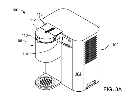
implying an absolute direction. For example, movement of a driveshaft
described as
vertically upwards or downwards relative to the orientation of the illustrated
system.
However, the translational motion of such a driveshaft depends on the
orientation of the
system and is not necessarily vertical.
[0100] The details of one or more embodiments of these systems and methods are
set forth in the accompanying drawings and the description below. Other
features,
objects, and advantages of these systems and methods will be apparent from the
description and drawings, and from the claims.
DESCRIPTION OF FIGURES
[0101] Figure 1 is a process diagram for an approach to manufacturing ice
cream.
[0102] Figures 2A-2D illustrate ice crystals in ice cream related to
smoothness,
churning, and draw temperature.
[0103] Figure 3A is a perspective view of a machine for rapidly cooling food
and
drinks. Figure 3B shows the machine without its housing. Figure 3C is a
perspective
view of a portion of the machine of Figure 3A.
[0104] Figure 4A is perspective view of the machine of Figure 3A with the
cover
of the pod-machine interface illustrated as being transparent to allow a more
detailed
view of the evaporator to be seen. Figure 4B is a top view of a portion of the
machine
without the housing and the pod-machine interface without the lid. Figures 4C
and 4D
are, respectively, a perspective view and a side view of the evaporator.
[0105] Figures 5A ¨ 5F show components of a pod-machine interface that are
operable to open and close pods in the evaporator to dispense the food or
drink being
produced.
[0106] Figure 6 is a schematic of a refrigeration system.
[0107] Figures 7A and 7B are views of a prototype of a condenser.
[0108] Figure 8A is a side view of a pod. Figure 8B is a schematic side view
of
the pod and a mixing paddle disposed in the pod.
22
Date Recue/Date Received 2022-07-15
CA 03169157 2022-07-15
WO 2021/146547
PCT/US2021/013619
[0109] Figures 9A and 9B are perspective views of a pod and an associated
driveshaft. Figure 9C is a cross-sectional view of a portion of the pod with
the driveshaft
126 engaged with a mixing paddle in the pod.
[0110] Figure 10A ¨ 10D shows a first end of a pod with its cap spaced apart
from
its base for ease of viewing.
[0111] Figures 11A¨ 11G illustrate rotation of a cap around the first end of
the
pod to open an aperture extending through the base.
[0112] Figure 12 is an enlarged schematic side view of a pod.
[0113] Figures 13A-13D are views of a can for a pod with seamed ends.
[0114] Figure 14A is a photo of a retort machine. Figure 14B is a photo of
retort
sterilization chambers inside a retort machine.
[0115] Figure 15 is a flow chart of a method for operating a machine for
producing cooled food or drinks.
[0116] Figure 16A-16C is a detailed flow chart of a method for operating a
machine for producing cooled food or drinks.
[0117] Figures 17A¨ 17D are perspective views of a machine for producing
cooled food or drinks.
[0118] Figures 18A and 18B are partial cross-sectional views of the machine of
Figures 17A¨ 17D.
[0119] Figure 19 is a partially cutaway perspective view of a driveshaft.
[0120] Figure 20 is a perspective view of a dispenser.
[0121] Figures 21A ¨ 21C are schematic views that illustrate a wedge system
associated with the pod-machine interface.
[0122] Figures 22A¨ 22C are schematic views of a driveshaft with a barbed head
and a matching recess on a mixing paddle.
[0123] Figure 23 shows a perspective view of a machine with a handle connected
to a pinion.
[0124] Figures 24A-24E show perspective and cross sectional views of a machine
with a handle that rotates on the same axis as a lid of the machine.
23
Date Recue/Date Received 2022-07-15
CA 03169157 2022-07-15
WO 2021/146547
PCT/US2021/013619
[0125] Figures 25A-25C show a portion of a machine with a spring-loaded handle
that rotates on the same axis as a lid of the machine.
[0126] Figures 26A-26C are perspective views of a machine for rapidly cooling
food and drinks. Figure 26B is the machine with the top cover removed.
[0127] Figures 27A-27B are perspective views of the machine of Figures 26A-
26C with internal details shown.
[0128] Figures 28A-28D are perspective and cross-sectional views of a machine
with an automatic plunger in a retracted position (Figures 28A and 28B) and in
an
engaged position (Figures 28C and 28D).
[0129] Figures 29A-29D are partial perspective and plan views of a machine
with
a self-driven plunger in a retracted position (Figures 29A and 29B) and in an
engaged
position (Figures 29C and 29D).
[0130] Figure 30 is a partial cross-sectional view of a machine with a self-
driven
plunger as it moves from an engaged position to a retracted position.
[0131] Figure 31 is view of the internal components of a machine with an
evaporator with an attached motor.
[0132] Figure 32A and 32B are perspective views an evaporator with an attached
motor.
[0133] Figures 33A-33B are schematics of a refrigeration system.
[0134] Figures 34A-34D are perspective and plan views of a mixing paddle.
[0135] Figures 35A-35C illustrate the engagement of a mixing paddle with a
pod.
[0136] Figures 36A-36B illustrate a polymer liner of a pod.
[0137] Figures 37A-37B illustrate a grommet on a driveshaft. Figures 37C-37D
are views of grommets.
[0138] Figures 38A-38D are perspective views of a mixing paddle with dog-ears
disposed inside a pod (Figure 38A), alone (Figure 38B), and with a connector
attached
(Figures 38C and 38D).
[0139] Figure 39A is a perspective view of mixing paddle using a sealed
connection to a pod. Figure 39B is a perspective view of the exterior of the
pod shown in
Figure 39A.
24
Date Recue/Date Received 2022-07-15
CA 03169157 2022-07-15
WO 2021/146547
PCT/US2021/013619
[0140] Figure 40A is a plan view of a mixing paddle using an alternate sealed
connection to a pod. Figure 40B is a perspective view of the mixing paddle
showing a
portion of the sealed connection shown in Figure 40A. Figure 40C is a
perspective view
of the mixing paddle and the portion of the seal shown in Figure 40B.
[0141] Figure 41A is a perspective view of mixing paddle using an alternate
sealed connection to a pod. Figure 41B is the seal shown in Figure 41A. Figure
40C is
the coupling shown in Figure 41A. Figure 41D is a plan view of the mixing
paddle and
the alternate sealed connection shown in Figure 41A. Figure 41E is a
perspective view of
the mixing paddle and the alternate sealed connection shown in Figure 41A with
the pod
hidden. Figure 41F is a plan view of the mixing paddle and the alternate
sealed
connection shown in Figure 41A with the pod hidden.
[0142] Figures 42A-42D are perspective and plan views of a mixing paddle using
an alternate sealed connection to a pod.
[0143] Figures 43A-43C are perspective views of a mixing paddle with eccentric
windows.
[0144] Figures 44A-44B are perspective views of a cam system to engage a pod.
[0145] Figures 45A-45E are perspective views the cam system engaging a pod.
[0146] Figure 46 illustrate a machine with a cam system engaging a pod.
[0147] Figures 47A-47B illustrate a cap for a pod.
[0148] Figures 48A-48C are schematics of a vending machine including a
machine for producing cooled food or drinks.
[0149] Figure 49 are ice crystal size analysis results for ice cream.
[0150] Figures 50A-50E are images representing an ice crystal size analysis
for
various ice creams.
[0151] Figures 51A-51E are histograms representing the ice crystal size
analysis
for the various ice creams shown in Figures 50A-50E.
[0152] Like reference symbols in the various drawings indicate like elements.
Date Recue/Date Received 2022-07-15
CA 03169157 2022-07-15
WO 2021/146547
PCT/US2021/013619
DETAILED DESCRIPTION
[0153] This specification describes systems and methods for rapidly cooling
food
and drinks. Some of these systems and methods use a counter-top or installed
machine to
cool food and drinks in a container from room temperature to freezing in less
than three
minutes. For example, the approach described in this specification has
successfully
demonstrated the ability make soft-serve ice cream, frozen coffees, frozen
smoothies, and
frozen cocktails, from room temperature pods in approximately 90 seconds. This
approach can also be used to chill cocktails, create frozen smoothies, frozen
protein and
other functional beverage shakes (e.g., collagen-based, energy, plant-based,
non-dairy,
and CBD shakes), frozen coffee drinks and chilled coffee drinks with and
without
nitrogen in them, create hard ice cream, create milk shakes, create frozen
yogurt and
chilled probiotic drinks. These systems and methods are based on a
refrigeration cycle
with low startup times and a pod-machine interface that is easy to use and
provides
extremely efficient heat transfer. Some of the pods described can be
sterilized (e.g., using
retort sterilization or aseptic filling) and used to store ingredients
including, for example,
dairy products at room temperature for up to 18 months. These machines are
described in
more detail in U.S. Pat. App. Ser. No. 16/459,176 (attorney docket number
47354-
0009001) filed July 1, 2019 and incorporated herein by reference in its
entirety.
[0154] A significant challenge in the design of ice cream machines is the
ability to
cool a pod from room temperature to the draw temperature as quickly as
possible,
preferably within two minutes. Some machines reduce the residence time the ice
cream
remains in the ice cream machine by reaching the draw temperature as quickly
as
possible. This can be achieved by mixing and cooling as quickly as possible.
[0155] The machines and processes described in this specification create ice
cream with the majority of the ice crystals below 50 m and often the majority
is below
30 m in a single serve pod. In order to still be able to dispense the ice
cream out of the
pod into a bowl or dish without the ice cream contacting the machine, a draw
temperature
or dispensing temperature of the ice cream should be between -3 to -8 C
(26.6 F to
17.6 F) and preferably between -3 to -6 C (26.6 F to 21.2 F).
26
Date Recue/Date Received 2022-07-15
CA 03169157 2022-07-15
WO 2021/146547
PCT/US2021/013619
[0156] The machines and processes described in this specification use a novel
feature of increasing the rotational speed during freezing and dispensing,
which is
counter-intuitive. The machines described in this specification can use a
mixing paddle
that begins rotating slowly, but as the ice cream starts to freeze from liquid
to solid, the
rotational speed is increased requiring much more power to overcome the
increase in
mixing paddle torque. Normally as torque increases one would slow down the
rotational
speed of the mixing paddle to keep the power requirement constant. In some
machines,
the rotational speed of the mixing paddle is increased during freezing process
from 100
RPM to 1200 RPM to reduce freeze times and reduce ice crystal size to be low,
around
50 m.
[0157] Furthermore, by increasing the rotational speed of the mixing paddle,
ice
on the inner diameter of the pod is melted, which is opposite the intended
function of the
pod wall to freeze the ice cream quickly. The freeze time for the ice cream
increases by
melting the ice crystals at the pod wall with the extra friction generated by
the high
rotational speed of the mixing paddle. This is opposite the typical goal of
reducing
consumer the wait time for the ice cream to freeze and dispense. For at least
these
reasons, increasing the rotational speed of the mixing paddle above a
threshold of about
200 RPM is counter-intuitive.
[0158] The rotational speed of the impeller mixing paddle is increased to draw
air
into the frozen confection to achieve improved overrun (preferably at least
30% overrun).
Rotation of the helical profile of the mixing paddle (for example, the helical
profile of the
mixing paddle 950 is shown in Figure 34A) also generates downward pressure to
extrude
the ice cream out of the exit port of the pod.
[0159] Furthermore, as previously described, the combination of spinning the
mixing paddle quickly and cooling rapidly at the walls of the pod allows the
cooled ice
cream to mix properly within the pod and maintain small ice crystal size which
is directly
correlated to ice cream smoothness. This is in part because of scraping the
chilled ice
cream from the walls of the pod and forcing it to the center of the pod where
the
temperature is warmer. Optimal performance of the ice cream machine relies of
having
both efficient cooling at the walls of the pod and rapid scraping/mixing of
the contents of
27
Date Recue/Date Received 2022-07-15
CA 03169157 2022-07-15
WO 2021/146547
PCT/US2021/013619
the pod. A machine with efficient cooling but without rapid scraping/mixing
and vice
versa would be less optimal.
[0160] The ice cream mix described in this specification uses a novel feature
of
includes minimal or no stabilizers and emulsifiers. The absence or near
absence of
stabilizers, emulsifiers, and unnatural products, is considered a "clean
label". The ice
cream mix described in this specification includes milk, cream, sugar and
powder milk.
By including these features in the ice cream mix, the resulting ice cream has
a majority of
ice crystals under 251.im in diameter.
[0161] For example, a clean label formulation for a 150g serving of ice cream
can
include the following proportions: 48g of whole milk, 67g of heavy cream (no
gums),
24g of white sugar, and llg of non-fat dry milk powder
[0162] Figure 3A is a perspective view of a machine 100 for cooling food or
drinks. Figure 3B shows the machine without its housing. The machine 100
reduces the
temperature of ingredients in a pod containing the ingredients. Most pods
include a
mixing paddle used to mix the ingredients before dispensing the cooled or
frozen
products. In some instances, the mixing paddle can be part of the machine and
inserted
into the pod. In some instances, the mixing paddle can be used more than once.
In some
instances, the machine will not dispense the frozen confection and in this
case the frozen
confection can be scooped out of the pod with a spoon.
[0163] The machine 100 includes a body 102 that includes a compressor, a
condenser, a fan, an evaporator, capillary tubes, a control system, a lid
system and a
dispensing system with a housing 104 and a pod-machine interface 106. The pod-
machine interface 106 includes an evaporator 108 of a refrigeration system 109
whose
other components are disposed inside the housing 104. As shown on Figure 3B,
the
evaporator 108 defines a receptacle 110 sized to receive a pod.
[0164] A lid 112 is attached to the housing 104 via a hinge 114. The lid 112
can
rotate between a closed position covering the receptacle 110 (Figure 3A) and
an open
position exposing the receptacle 110 (Figure 3B). In its closed position, the
lid 112 covers
the receptacle 110 and is locked in place. In the machine 100, a latch 116 on
the lid 112
engages with a latch recess 118 on the pod-machine interface 106. A latch
sensor 120 is
28
Date Recue/Date Received 2022-07-15
CA 03169157 2022-07-15
WO 2021/146547
PCT/US2021/013619
disposed in the latch recess 118 to determine if the latch 116 is engaged with
the latch
recess 118. A processor 122 is electronically connected to the latch sensor
120 and
recognizes that the lid 112 is closed when the latch sensor 120 determines
that the latch
116 and the latch recess 118 are engaged. Not all machines include latch
sensors.
[0165] An auxiliary cover 115 rotates upward as the lid 112 is moved from its
closed position to its open position. A slot in the auxiliary cover 115
receives a handle of
the lid 112 during this movement. Some auxiliary covers slide into the housing
when the
lid moves into the open position.
[0166] In the machine 100, the evaporator 108 is fixed in position with
respect to
the body 102 of the machine 100 and access to the receptacle 110 is provided
by
movement of the lid 112. In some machines, the evaporator 108 is displaceable
relative to
the body 102 and movement of the evaporator 108 provides access to the
receptacle 110.
[0167] A motor 124 disposed in the housing 104 is mechanically connected to a
driveshaft 126 that extends from the lid 112. When the lid 112 is in its
closed position, the
driveshaft 126 extends into the receptacle 110 and, if a pod is present,
engages with the
pod to move a paddle or paddles within the pod. Sometimes the paddle is
referred to as an
impeller, a blade, a dasher, or a mixing paddle. The processor 122 is in
electronic
communication with the motor 124 and controls operation of the motor 124.
[0168] In some machines, the shaft associated with the paddle(s) of the pod
extends outward from the pod and the lid 112 has a rotating receptacle
(instead of the
driveshaft 126) mechanically connected to the motor 124. In some machines, the
motor
provides at least 50 ozf-in (ounce-force inch) of torque at a rotational
velocity of at least
100 RPM (rotations per minute) at the mixing paddle. For example, a torque of
100 ozf-
in and a rotational speed of 750 RPM may be used. In some machines, the motor
of the
mixing paddle provides a torque of up to 400 ozf-in and a rotational speed of
up to 1,500
RPM.
[0169] Figure 3C is perspective view of the lid 112 shown separately so the
belt
125 that extends from motor 124 to the driveshaft 126 is visible. Referring
again to
Figure 3B, the motor 124 is mounted on a plate that runs along rails 127. The
plate can
move approximately 0.25 inches to adjust the tension on the belt 125. During
assembly,
29
Date Recue/Date Received 2022-07-15
CA 03169157 2022-07-15
WO 2021/146547
PCT/US2021/013619
the plate slides along the rails. Springs disposed between the plate and the
lid 112 bias the
lid 112 away from the plate to maintain tension in the belt.
[0170] Figure 4A is a perspective view of the machine 100 with the cover of
the
pod-machine interface 106 illustrated as being transparent to allow a more
detailed view
of the evaporator 108 to be seen. Figure 4B is atop view of a portion of the
machine 100
without housing 104 and the pod-machine interface 106 without the lid 112.
Figures 4C
and 4D are, respectively, a perspective view and a side view of the evaporator
108. The
evaporator 108 is described in more detail in U.S. Pat. App. Ser. No.
16/459,388
(attorney docket number 47354-0006001) filed July 1, 2019 and incorporated
herein by
reference in its entirety.
[0171] The evaporator 108 has a clamshell configuration with a first portion
128
attached to a second portion 130 by a living hinge 132 on one side and
separated by a gap
134 on the other side. Refrigerant flows to the evaporator 108 from other
components of
the refrigeration system through fluid channels 136 (best seen on Figure 4B).
The
refrigerant flows through the evaporator 108 in internal channels through the
first portion
128, the living hinge 1132, and the second portion 130.
[0172] The space 137 (best seen on Figure 4B) between the outer wall of the
evaporator 108 and the inner wall of the casing of the pod-machine interface
106 is filled
with an insulating material to reduce heat exchange between the environment
and the
evaporator 108. In the machine 100, the space 137 is filled with an aerogel
(not shown).
Some machines use other insulating material, for example, an annulus (such as
an
airspace), insulating foams made of various polymers, or fiberglass wool.
[0173] The evaporator 108 has an open position and a closed position. In the
open
position, the gap 134 opens to provide an air gap between the first portion
128 and the
second portion 130. In the machine 100, the first portion 128 and the second
portion 130
are pressed together in the closed position.
[0174] The inner diameter ID of the evaporator 108 is slightly larger in the
open
position than in the closed position. Pods can inserted into and removed from
the
evaporator 108 while the evaporator is in its open position. Transitioning the
evaporator
108 from its open position to its closed position after a pod is inserted
tightens the
Date Recue/Date Received 2022-07-15
CA 03169157 2022-07-15
WO 2021/146547
PCT/US2021/013619
evaporator 108 around the outer diameter of the pod. For example, the machine
100 is
configured to use pods with 2.085" outer diameter. The evaporator 108 has an
inner
diameter of 2.115" in the open position and an inner diameter inner diameter
of 2.085" in
the closed position. The evaporator 108 has an inner diameter of 2.115 inches
in its open
position and an inner diameter inner diameter of 2.085 inches in its closed
position.
Some machines have evaporators sized and configured to cool other pods.
[0175] The evaporator is sized to easily receive a pod in the open position
and
engage the pod in the closed position. Instead of a clamshell configuration,
some
evaporators can have multiple pieces that have an opened and closed position
that do not
hinge but can slide into close proximity with one another. Some evaporators
can have a
tube connecting the cooling channels between the various pieces of the
evaporator. Some
evaporators can be frustoconical. Some evaporators have first and second
portions that
are pressed towards each other and a gap between them is reduced, but a space
between
the first and second portions exists in the closed position.
[0176] Some machines have evaporators sized and configured to cool other pods.
The pods can be formed from commercially available can sizes, for example,
"slim" cans
with diameters ranging from 2.080 inches - 2.090 inches and volumes of 180
milliliters
(m1) - 300 ml, "sleek" cans with diameters ranging from 2.250 inches ¨ 2.400
inches and
volumes of 180 ml ¨ 400 ml and "standard" size cans with diameters ranging
from 2.500
inches ¨ 2.600 inches and volumes of 200 ml ¨ 500 ml. The machine 100 is
configured
to use pods with 2.085 0.10 inches outer diameter. Some pods have an inner
diameter
of 2.065 inches to 2.075 inches to allow the mixing paddle with a diameter of
2.045 to
2.055 inches, respectively, to rotate at an RPM of 100 to 1,500 RPM, resulting
in 6,000 to
93,000 square inches scraped per minute.
[0177] With an inner diameter of about 2.085 inches, the pod can accommodate a
mixing paddle with a diameter of about 2.065 inches. The mixing paddle can
revolve in
the pod at rotational speeds ranging between 100 RPM and 1,500 RPM. During
this time
a single blade edge of the mixing paddle scrapes the internal walls of the pod
at rates
ranging from 3,100 to 46,500 square inches per minute. The scraped area per
minute
multiplies with each scraping edge on the mixing paddle (i.e., a mixing paddle
with two
31
Date Recue/Date Received 2022-07-15
CA 03169157 2022-07-15
WO 2021/146547
PCT/US2021/013619
edges would scrape approximately 6,200 to 93,000 square inches per minute). As
previously described, this scraping and mixing process helps distribute the
ice crystals
that formed at the wall of the pod to the interior of the pod.
[0178] Some pods are pressurized to have an internal pressure of around 5 ¨
100
psi gauge pressure. Some pods have a decorative external coating of no more
than 10-50
microns thickness (e.g., less than 50 microns). Thicker external coatings can
insulate the
pod and interfere with heat transfer during cooling of the pod. Some pods do
not have an
internal or external coating on the ends.
[0179] In addition to cylindrical pods, some pods are frustoconical (e.g.,
frustoconical with an open end). Some pods do not require a dispensing port
because the
frozen confection can be spooned out from the open end of the pod.
[0180] In addition to single-use pods, some pods are reusable. Some pods are
used, washed, and reused. Some pods are be purchased empty and filled before
use.
Some pods are be purchased or acquired full, used, and refilled by a user or
by the
machine. Some pods are sterilized after use and sterilized after refill using
to enable
room temperature storage. Some pods include resealed features that allow the
pod to be
refilled and resealed. Some pods include a reusable protrusion for dispensing
the frozen
confection of the pod from the machine. Some pods can be purchased empty and
used
with a home ice cream making kit with clean-label ingredients.
[0181] The closed position of evaporator 108 improves heat transfer between
inserted pod 150 and the evaporator 108 by increasing the contact area between
the pod
150 and the evaporator 108 and reducing or eliminating an air gap between the
wall of
the pod 150 and the evaporator 108. In some pods, the pressure applied to the
pod by the
evaporator 108 is opposed by the mixing paddles, pressurized gases within the
pod, or
both to maintain the casing shape of the pod. Evaporator 108 can provide a
closure force
against the pod 150 of approximately 10 ¨ 50 lbf (pound-force) and an
approximate
torque clamping force of 1,000 to 1,500 ozf ¨ in.
[0182] In the evaporator 108, the relative position of the first portion 128
and the
second portion 130 and the size of the gap 134 between them is controlled by
two bars
138 connected by a bolt 140 and two springs 142. Each of the bars 138 has a
threaded
32
Date Recue/Date Received 2022-07-15
CA 03169157 2022-07-15
WO 2021/146547
PCT/US2021/013619
central hole through which the bolt 140 extends and two end holes engaging the
pins 144.
Each of the two springs 142 is disposed around a pin 144 that extends between
the bars
138. Some machines use other systems to control the size of the gap 134, for
example,
circumferential cable systems with cables that extend around the outer
diameter of the
evaporator 108 with the cable being tightened to close the evaporator 108 and
loosened to
open the evaporator 108. In other evaporators, there are a plurality of bolts
and end
holes, one or more than two springs, and one or more than engaging pins.
[0183] One bar 138 is mounted on the first portion 128 of the evaporator 108
and
the other bar 138 is mounted on the second portion 130 of the evaporator 108.
In some
evaporators, the bars 138 are integral to the body of the evaporator 108
rather than being
mounted on the body of the evaporator. The springs 142 press the bars 138 away
from
each other. The spring force biases the first portion 128 and the second
portion 130 of the
evaporator 108 away from each at the gap 134. Rotation of the bolt 140 in one
direction
increases a force pushing the bars 138 towards each and rotation of the bolt
in the
opposite direction decreases this force. When the force applied by the bolt
140 is greater
than the spring force, the bars 138 bring the first portion 128 and the second
portion 130
of the evaporator together.
[0184] The machine 100 includes an electric motor 146 (shown on Figure 4B)
that is operable to rotate the bolt 140 to control the size of the gap 134.
Some machines
use other mechanisms to rotate the bolt 140. For example, some machines use a
mechanical linkage, for example, between the lid 112 and the bolt 140 to
rotate the bolt
140 as the lid 112 is opened and closed. Some machines include a handle that
can be
attached to the bolt to manually tighten or loosen the bolt. Some machines
have a wedge
system that forces the bars into a closed position when the machine lid is
shut. This
approach may be used instead of the electric motor 146 or can be provided as a
backup in
case the motor fails.
[0185] The electric motor 146 is in communication with and controlled by the
processor 122 of the machine 100. Some electric drives include a torque sensor
that sends
torque measurements to the processor 122. The processor 122 signals to the
motor to
rotate the bolt 140 in a first direction to press the bars 138 together, for
example, when a
33
Date Recue/Date Received 2022-07-15
CA 03169157 2022-07-15
WO 2021/146547
PCT/US2021/013619
pod sensor indicates that a pod is disposed in the receptacle 110 or when the
latch sensor
120 indicates that the lid 112 and pod-machine interface 106 are engaged. It
is desirable
that the clamshell evaporator be shut and holding the pod in a tightly fixed
position
before the lid closes and the shaft pierces the pod and engages the mixing
paddle. This
positioning can be important for shaft-mixing paddle engagement. The processor
122
signals to the electric drive to rotate the bolt 140 in the second direction,
for example,
after the food or drink being produced has been cooled/frozen and dispensed
from the
machine 100, thereby opening the evaporator gap 134 and allowing for easy
removal of
pod 150 from evaporator 108.
[0186] The base of the evaporator 108 has three bores 148 (see Figure 4C)
which
are used to mount the evaporator 108 to the floor of the pod-machine interface
106. All
three of the bores 148 extend through the base of the second portion 130 of
the
evaporator 108. The first portion 128 of the evaporator 108 is not directly
attached to the
floor of the pod-machine interface 106. This configuration enables the opening
and
closing movement described above. Other configurations that enable the opening
and
closing movement of the evaporator 108 can also be used. Some machines have
more or
fewer than three bores 148. Some evaporators are mounted to components other
than the
floor of the pod-machine interface, for example, the dispensing mechanism.
[0187] Many factors affect the performance of a refrigeration system.
Important
factors include mass velocity of refrigerant flowing through the system, the
refrigerant
wetted surface area, the refrigeration process, the area of the pod/evaporator
heat transfer
surface, the mass of the evaporator, and the thermal conductivity of the
material of the
heat transfer surface. Extensive modeling and empirical studies in the
development of
the prototype systems described in this specification have determined that
appropriate
choices for the mass velocity of refrigerant flowing through the system and
the
refrigerant wetted surface area are the most important parameters to balance
to provide a
system capable of freezing up to 10-12 ounces of confection in less than 2
minutes.
34
Date Recue/Date Received 2022-07-15
CA 03169157 2022-07-15
WO 2021/146547
PCT/US2021/013619
[0188] The evaporators described in this specification have the following
characteristics:
Mass Velocity 60,000 to 180,000 lb /(hour feet squared)
Refrigerant Wetted Surface Area 35 to 110 square inches
Pressure drop Through Refrigeration less than 2 psi pressure drop across
the
Process evaporator
Pod/Evaporator Heat Transfer Surface 15 to 50 square inches
Mass of Evaporator 0.100 to 1.50 pounds
Conductivity of the Material 160 W/mK
The following paragraphs describe the significance of these parameters in more
detail.
[0189] Mass velocity accounts for the multi-phase nature or refrigerant
flowing
through an evaporator. The two-phase process takes advantage of the high
amounts of
heat absorbed and expended when a refrigerant fluid (e.g., R-290 propane)
changes state
from a liquid to gas and a gas to a liquid, respectively. The rate of heat
transfer depends
in part on exposing the evaporator inner surfaces with a new liquid
refrigerant to vaporize
and cool the liquid ice cream mix. To do this the velocity of the refrigerant
fluid must be
high enough for vapor to channel or flow down the center of the flow path
within the
walls of evaporator and for liquid refrigerant to be pushed thru these channel
passages
within the walls. One approximate measurement of fluid velocity in a
refrigeration
system is mass velocity - the mass flow of refrigerant in a system per unit
cross sectional
area of the flow passage in units of pounds /(hour¨ square foot) (lb/hr ft2).
Velocity as
measured in feet / second (ft/s) (a more familiar way to measure "velocity")
is difficult to
apply in a two-phase system since the velocity (ft/s) is constantly changing
as the fluid
flow changes state from liquid to gas. If liquid refrigerant is constantly
sweeping across
the evaporator walls, it can be vaporized and new liquid can be pushed against
the wall of
the cooling channels by the "core" of vapor flowing down the middle of the
passage. At
low velocities, flow separates based on gravity and liquid remains on the
bottom of the
cooling passage within the evaporator and vapor rises to the top side of the
cooling
passage channels. If the amount of area exposed to liquid is reduced by half,
for
example, this could cut the amount of heat transfer almost half.
[0190] According to the American Society of Heating, Refrigerating and Air-
Conditioning Engineers (ASHRAE), a mass velocity of 150,000 lb/hr ftA2
maximizes
Date Recue/Date Received 2022-07-15
CA 03169157 2022-07-15
WO 2021/146547
PCT/US2021/013619
performance for the majority of the evaporator flow path. Mass velocity is one
of the
parameters that must be balanced to optimize a refrigerant system. The
parameters that
affect the performance of the evaporator are mass flow rate, convective heat
transfer
coefficient, and pressure drop. The nominal operating pressure of the
evaporator is
determined by the required temperature of the evaporator and the properties of
the
refrigerant used in the system. The mass flow rate of refrigerant through the
evaporator
must be high enough for it to absorb the amount of thermal energy from the
confection to
freeze it, in a given amount of time. Mass flow rate is primarily determined
by the size of
the compressor. It is desirable to use the smallest possible compressor to
reduce, cost,
weight and size. The convective heat transfer coefficient is influenced by the
mass
velocity and wetted surface area of the evaporator. The convective heat
transfer
coefficient will increase with increased mass velocity. However, pressure drop
will also
increase with mass velocity. This in tum increases the power required to
operate the
compressor and reduces the mass flow rate the compressor can deliver. It is
desirable to
design the evaporator to meet performance objectives while using the smallest
least
expensive compressor possible. We have determined that evaporators with a mass
velocity of 75,000 ¨ 125,000 lb/hr ftA2 are effective in helping provide a
system capable
of freezing up to 12 ounces of confection in less than 2 minutes. The latest
prototype has
a mass velocity of approximately 100,000 lb/hr ft^2 and provides a good
balance of high
mass velocity, manageable pressure drop in the system (under 2 psi), and a
reasonable
sized compressor below 12cc displacement
[0191] In some systems, the refrigeration system cools the pod with a
compressor
using a two-phase refrigerant fluid, such as R134A, R22, R600a, or R290. In
some
systems the compressor is a reciprocating compressor or a rotary compressor.
Direct
Current (DC) compressors with a variable motor speed allow for increased
displacement
towards the beginning of the refrigeration cooling cycle of the pod (e.g.,
first 45 seconds
of cooling the pod) and slow down the motor speed towards the end of the
cooling cycle
of the pod in order to increase the efficiency of the freezing process while
maintaining the
pressure drop. In some systems, the DC compressor can have a variable motor
speed that
is adjusted depending on the load on the machine's refrigeration cycle.
36
Date Recue/Date Received 2022-07-15
CA 03169157 2022-07-15
WO 2021/146547
PCT/US2021/013619
[0192] In some systems, the use of a natural refrigerant, such as R290, can
meet
objectives of international protocols, such as Montreal and Kyoto, as well as
help reduce
environmental issues, such as ozone depletion and global warming. These
protocols and
environmental issues typically suggest that R22 and R134A refrigerants be
phased out.
[0193] Thermo-physical properties of refrigerants determine an energy
performance of the refrigeration system. The following table shows thermo-
physical
properties for refrigerants R22 and R290, at an evaporating temperature of 10
C and
condensing temperature of 45 C.
Property Temp State Refrigerant Refrigerant
(Degrees C) R22 R290
Saturation Pressure (MPa) 10 Liquid 0.640 0.601
45 Vapor 1.729 1.534
Density (kg/m^3) 10 Liquid 1253.8 517.56
45 Vapor 75.45 34.14
Viscosity (microPa-s) 10 Liquid 197.97 115.69
45 Vapor 13.69 9.13
Thermal conductivity (W/m 10 Liquid 0.0911 0.101
deg. C) 45 Vapor 0.0135 0.0224
Specific heat (kJ/kg deg C) 10 Liquid 1.1836 2.5318
45 Vapor 1.0487 2.3714
[0194] The lower liquid density of R290 refrigerant denotes the lower
requirement of refrigerant mass resulting in lower friction and better heat
transfer
coefficients in the evaporator and condenser. Refrigerant viscosity is the
major source of
irreversibility and influences condensation and boiling heat transfer
coefficients. R290
refrigerant has lower viscosity and higher thermal conductivity which improves
the
performance of condenser and evaporator. The higher specific heat of R290
gives lower
discharge temperatures.
[0195] Another important factor that affects performance in an evaporator is
the
surface area wetted by refrigerant which is the area of all the cooling
channels within the
evaporator as long as at least some liquid refrigerant is present throughout
these channels.
Increasing the wetted surface area can improve heat transfer characteristics
of an
evaporator. However, increasing the wetted surface area can increase the mass
of the
37
Date Recue/Date Received 2022-07-15
CA 03169157 2022-07-15
WO 2021/146547
PCT/US2021/013619
evaporator which would increase thermal inertia and degrade heat transfer
characteristics
of the evaporator.
[0196] The amount of heat that can be transferred out of the liquid in a pod
is
proportional ice cream mix to the surface area of the pod / evaporator heat
transfer
surface. A larger surface area is desirable but increases in surface area can
require
increasing the mass of the evaporator which would degrade heat transfer
characteristics
of the evaporator. We have determined that evaporators in which the area of
the
pod/evaporator heat transfer surface is between 20 and 40 square inches are
effectively
combined with the other characteristics to help provide a system capable of
freezing up to
12 ounces of confection in less than 2 minutes.
[0197] Thermal conductivity is the intrinsic property of a material which
relates
its ability to conduct heat. Heat transfer by conduction involves transfer of
energy within
a material without any motion of the material as a whole. An evaporator with
walls made
of a high conductivity material (e.g., aluminum) reduces the temperature
difference
across the evaporator walls. Reducing this temperature difference reduces the
work
required for the refrigeration system to cool the evaporator to the right
temperature.
[0198] The temperature of the pod can be measured using a temperature sensor,
such as a thermocouple. In some machines, a thermocouple physically touching
the
exterior surface of the pod can be used to measure the temperature of the pod,
or the
thermocouple can be provided directly on the exterior of the pod. In some
machines, the
sensor(s) penetrate radially through the evaporator and, in some cases, are
spring loaded
to ensure consistent force at the sensor tip. The sensor can be insulated
thermally from
the evaporator so it only senses the temperature of the outside of the pod.
Pods can be
made of approximately 0.004 to 0.008 inch thick aluminum such that the pod
temperature
is effectively the same as the temperature of the contents. Using these
temperatures the
process would be controllable in several ways: (i) by varying the mixer speed
depending
on how quickly the product freezes, (ii) by stopping the freezing process when
the target
temperature is achieved, and (iii) during the dispensing process, by sensing
when the pod
is empty and ending the dispensing process at that time, instead of spinning
the mixing
paddle in an empty pod, which can be noisy.
38
Date Recue/Date Received 2022-07-15
CA 03169157 2022-07-15
WO 2021/146547
PCT/US2021/013619
[0199] For the desired heat transfer to occur, the evaporator must be cooled.
The
greater the mass of the evaporator, the longer this cooling will take.
Reducing evaporator
mass reduces the amount of material that must be cooled during a freezing
cycle. An
evaporator with a large mass will increase the time require to freeze up to 12
ounces of
confection.
[0200] The effects of thermal conductivity and mass can be balanced by an
appropriate choice of materials. There are materials with higher thermal
conductivity
than aluminum such as copper. However, the density of copper is greater that
the density
of aluminum. For this reason, some evaporators have been constructed that use
high
thermal conductive copper only on the heat exchange surfaces of the evaporator
and use
aluminum everywhere else.
[0201] Figures 5A¨ 5F show components of the pod-machine interface 106 that
are operable to open pods in the evaporator 108 to dispense the food or drink
being
produced by the machine 100. This is an example of one approach to opening
pods but
some machines and the associated pods use other approaches.
[0202] Figure 5A is a partially cutaway schematic view of the pod-machine
interface 106 with a pod 150 placed in the evaporator 108. Figure 5B is a
schematic plan
view looking upwards that shows the relationship between the end of the pod
150 and the
floor 152 of the pod-machine interface 106. The floor 152 of the pod-machine
interface
106 is formed by a dispenser 153. Figures 5C and 5D are perspective views of a
dispenser 153. Figures 5E and 5F are perspective views of an insert 154 that
is disposed
in the dispenser 153. The insert 154 includes an electric motor 146 operable
to drive a
worm gear 157 floor 152 of the pod-machine interface 106. The worm gear 157 is
engaged with a gear 159 with an annular configuration. An annular member 161
mounted
on the gear 159 extends from the gear 159 into an interior region of the pod-
machine
interface 106. The annular member 161 has protrusions 163 that are configured
to engage
with a pod inserted into the pod-machine interface 106 to open the pod. The
protrusions
163 of the annular member 161 are four dowel-shaped protrusions. Some annular
gears
have more protrusions or fewer protrusions and the protrusions can have other
shapes, for
example, "teeth".
39
Date Recue/Date Received 2022-07-15
CA 03169157 2022-07-15
WO 2021/146547
PCT/US2021/013619
[0203] The pod 150 includes a body 158 containing a mixing paddle 160 (see
Figure 5A). The pod 150 also has a base 162 defining an aperture 164 and a cap
166
extending across the base 162 (see Figure 5B). The base 162 is seamed/fixed
onto the
body 158 of the pod 150. The base 162 includes a protrusion 165. The cap 166
mounted
over base 162 is rotatable around the circumference/axis of the pod 150. In
use, when the
product is ready to be dispensed from the pod 150, the dispenser 153 of the
machine
engages and rotates the cap 166 around the first end of the pod 150. Cap 166
is rotated to
a position to engage and then separate the protrusion 165 from the rest of the
base 162.
The pod 150 and its components are described in more detail with respect to
Figures 8A ¨
8B.
[0204] The aperture 164 in the base 162 is opened by rotation of the cap 166.
The
pod-machine interface 106 includes an electric motor 146 with threading that
engages the
outer circumference of a gear 168. Operation of the electric motor 146 causes
the gear
168 to rotate. The gear 168 is attached to an annular member 161 and rotation
of the gear
168 rotates the annular member 161. The gear 168 and the annular member 161
are both
annular and together define a central bore through which food or drink can be
dispensed
from the pod 150 through the aperture 164 without contacting the gear 168 or
the annular
member 161. When the pod 150 is placed in the evaporator 108, the annular
member 161
engages the cap 166 and rotation of the annular member 161 rotates the cap
166.
[0205] Figure 6 is a schematic of the refrigeration system 109 that includes
the
evaporator 108. The refrigeration system also includes a condenser 180, a
suction line
heat exchanger 182, an expansion device 184, and a compressor 186. The
expansion
device 184 can include a valve or a capillary tube both of which could be used
in the
refrigeration system 109. High-pressure, liquid refrigerant flows from the
condenser 180
through the suction line heat exchanger 182 and the expansion device 184 to
the
evaporator 108. The expansion device 184 restricts the flow of the liquid
refrigerant fluid
and lowers the pressure of the liquid refrigerant as it leaves the expansion
device 184.
The low-pressure liquid then moves to the evaporator 108 where heat is
absorbed from a
pod 150 and its contents in the evaporator 108 changes the refrigerant from a
liquid to a
gas. The gas-phase refrigerant flows from the evaporator 108 to the compressor
186
Date Recue/Date Received 2022-07-15
CA 03169157 2022-07-15
WO 2021/146547
PCT/US2021/013619
through the suction line heat exchanger 182. In the suction line heat
exchanger 182, the
cold vapor leaving the evaporator 108 pre-cools the liquid leaving the
condenser 180. The
refrigerant enters the compressor 186 as a low-pressure gas and leaves the
compressor
186 as a high-pressure gas. The gas then flows to the condenser 180 where heat
exchange
cools and condenses the refrigerant to a liquid.
[0206] The refrigeration system 109 includes a first bypass line 188 or valve
and
second bypass line 190 or valve. The first bypass line 188 directly connects
the discharge
of the compressor 186 to the inlet of the compressor 186. Disposed on the both
the first
bypass line and second bypass line are bypass valves that open and close the
passage to
allow refrigerant bypass flow. Diverting the refrigerant directly from the
compressor
discharge to the inlet can provide evaporator defrosting and temperature
control without
injecting hot gas to the evaporator. The first bypass line 188 also provides a
means for
rapid pressure equalization across the compressor 186, which allows for rapid
restarting
(i.e., freezing one pod after another quickly). The second bypass line 190
enables the
application of warm gas to the evaporator 108 to defrost the evaporator 108.
The bypass
valves may be, for example, solenoid valves or throttle valves. An additional
bypass
valve can be used (not shown) to direct warm air along the length of the
mixing paddle
160 to help remove product sticking to the mixing paddle 160.
[0207] Figures 7A and 7B are views of a prototype of the condenser 180. The
condenser has internal channels 192. The internal channels 192 increase the
surface area
that interacts with the refrigerant cooling the refrigerant quickly. These
images show
micro-channel tubing which are used because they have small channels which
keeps the
coolant velocity up and are thin wall for good heat transfer and have little
mass to prevent
the condenser for being a heat sink.
[0208] Figures 10A and 10B show an example of a pod 150 for use with the
machine 100 described with respect to Figures 3A¨ 5F. Figure 8A is a side view
of the
pod 150. Figure 8B is a schematic side view of the pod 150 and the mixing
paddle 160
disposed in the body 158 of the pod 150.
[0209] The pod 150 is sized to fit in the receptacle 110 of the machine 100.
The
pods can be sized to provide a single serving of the food or drink being
produced.
41
Date Recue/Date Received 2022-07-15
CA 03169157 2022-07-15
WO 2021/146547
PCT/US2021/013619
Typically, pods have a volume between 6 and 18 fluid ounces. The pod 150 has a
volume
of approximately 8.5 fluid ounces.
[0210] The body 158 of the pod 150 is an aluminum beverage can that contains
the mixing paddle 160. The body 158 extends from a first end 210 at the base
to a second
end 212 and has a circular cross-section. The first end 210 has a diameter DUE
that is
slightly larger than the diameter DEE of the second end 212. This
configuration facilitates
stacking multiple pods 150 on top of one another with the first end 210 of one
pod
receiving the second end 212 of another pod.
[0211] A sidewall 214 connects the first end 210 to the second end 212. The
wall
214 has a first neck 216, second neck 218, and a barrel 220 between the first
neck 216
and the second neck 218. The barrel 220 has a circular cross-section with a
diameter DB.
The diameter DB is larger than both the diameter DUE of the first end 210 and
the
diameter Du E of the second end 212. The first neck 216 connects the barrel
220 to the
first end 210 and slopes as the first neck 216 extends from the smaller
diameter DUE to
the larger diameter DB the barrel 220. The second neck 218 connects the barrel
220 to the
second end 212 and slopes as the second neck 218 extends from the larger
diameter DB of
the barrel 220 to the smaller diameter DEE of the second end 212. The second
neck 218 is
sloped more steeply than the first neck 216 as the second end 212 has a
smaller diameter
than the first end 210.
[0212] This configuration of the pod 150 provides increased material usage;
i.e.,
the ability to use more base material (e.g., aluminum) per pod. This
configuration further
assists with the columnar strength of the pod.
[0213] The pod 150 is designed for good heat transfer from the evaporator to
the
contents of the pod. The body 158 of the pod 150 is made of aluminum and is
between 5
and 50 microns thick. The bodies of some pods are made of other materials, for
example,
tin, stainless steel, and various polymers such as polyethylene terephthalate
(PTE).
[0214] Pod 150 may be made from a combination of different materials to assist
with the manufacturability and performance of the pod. In one embodiment, the
pod
walls and the second end 212 may be made of Aluminum 3104 while the base may
be
made of Aluminum 5182.
42
Date Recue/Date Received 2022-07-15
CA 03169157 2022-07-15
WO 2021/146547
PCT/US2021/013619
[0215] In some pods, the internal components of the pod are coated with a
lacquer
to prevent corrosion of the pod as it comes into contact with the ingredients
contained
within pod. This lacquer also reduces the likelihood of "off notes" of the
metal in the
food and beverage ingredients contained within pod. For example, a pod made of
aluminum may be internally coated with one or a combination of the following
coatings:
Sherwin WilliamsNalspar V70Q11, V70Q05, 32S02AD, 40Q60AJ; PPG Innovel 2012-
823, 2012-820C; and/or Alczo Nobel Aqualure G1 50. Other coatings made by the
same
or other coating manufacturers may also be used.
[0216] Some mixing paddles are made of similar aluminum alloys and coated
with similar lacquers/coatings. For example, Whitford/PPG coating 8870 may be
used as
a coating for mixing paddles. The mixing paddle lacquer may have additional
non-stick
and hardening benefits for mixing paddle. Some mixing paddles are made of AL
5182-
H48 or other aluminum alloys. Some mixing paddles exhibit a tensile strength
of 250 -
310 MPa minimum, a yield strength of 180 ¨ 260 MPa minimum, and an elongation
at
break of 4% - 12%.
[0217] In some machines, the mixing paddles can be reusable by removing from
the pod, washing them, and reusing them in the same or another pod.
[0218] In addition to the functionally of the mixing paddles previously
discussed,
some machines oscillate and/or vibrate the mixing paddles to help remove
product
sticking to the mixing paddle. This approach can be enabled by a machine (such
as
machine 100) which includes a solenoid that oscillates and/or vibrates the
mixing paddle.
[0219] Other pod-machine interfaces that can be used with this and similar
machines are described in more detail in U.S. Pat. App. Ser. No. 16/459,322
(attorney
docket number 47354-0010001) filed July 1, 2019 and incorporated herein by
reference
in its entirety.
[0220] Some pods include a seal configured to be broken upon an applied torque
by the mixing motor. Such a pod design can be easier and cheaper to
manufacture for
compatibility with machines,
[0221] Figures 9A ¨ 9C illustrate the engagement between the driveshaft 126 of
the machine 100 and the mixing paddle 160 of a pod 150 inserted in the machine
100.
43
Date Recue/Date Received 2022-07-15
CA 03169157 2022-07-15
WO 2021/146547
PCT/US2021/013619
Figures 9A and 9B are perspective views of the pod 150 and the driveshaft 126.
In use,
the pod 150 is inserted into the receptacle 110 of the evaporator 108 with the
first end 210
of the pod 150 downward. This orientation exposes the second end 212 of the
pod 150 to
the driveshaft 126 as shown in Figure 9A. Closing the lid 112 (see Figure 3A)
presses the
driveshaft 126 against the second end 212 of the pod 150 with sufficient force
that the
driveshaft 126 pierces the second end 212 of the pod 150. In some machines,
the
downward force of the piercing action of the driveshaft 126 into the second
end 212 of
the pod 150 is approximately 50 lbf. Downward forces of between 15 ¨ 65 lbf
are
effective in piercing the second end of the pod without damaging other
portions of the
pod.
[0222] Figure 9B shows the resulting hole and the mixing paddle 160 visible
through the hole. The driveshaft 126 is shown offset for ease of viewing.
Figure9C is a
cross-section of a portion of the pod 150 with the driveshaft 126 engaged with
the mixing
paddle 160 after the lid is closed. Typically, there is not a tight seal
between the
driveshaft 126 and the pod 150 so that air can flow in as the frozen
confection is
evacuating/dispensing out the other end of the pod 150. In an alternative
embodiment,
there is a tight seal such that the pod 150 retains pressure in order to
enhance contact
between the pod 150 and evaporator 108.
[0223] Some mixing paddles contain a funnel or receptacle configuration that
receives the punctured end of the second end of the pod when the second end is
punctured by driveshafi.
[0224] Figure 10A shows the first end 210 of the pod 150 with the cap 166
spaced
apart from the base 162 for ease of viewing. Figures 11A ¨ 11G illustrate
rotation of the
cap 166 around the first end 210 of the pod 150 to cut and carry away
protrusion 165 of
base 162 and expose aperture 164 extending through the base 162.
[0225] The base 162 is manufactured separately from the body 158 of the pod
150
and then attached (for example, by crimping or seaming) to the body 158 of the
pod 150
covering an open end of the body 158. The protrusion 165 of the base 162 can
be formed,
for example, by stamping, deep drawing, or heading a sheet of aluminum being
used to
form the base. The protrusion 165 is attached to the remainder of the base
162, for
44
Date Recue/Date Received 2022-07-15
CA 03169157 2022-07-15
WO 2021/146547
PCT/US2021/013619
example, by a weakened score line 173. The scoring can be a vertical score
into the base
of the aluminum sheet or a horizontal score into the wall of the protrusion
165. For
example, the material can be scored from an initial thickness of 0.008 inches
to 0.010
inches (e.g., the initial thickness can be 0.008 inches) to a post-scoring
thickness of 0.001
inches - 0.008 inches (e.g, the score thickness can be 0.002 inches).
[0226] Figure 10B shows a cross section of the first end 210 of the pod 150
illustrating the base 162, the protrusion 165, and the weakened score line
173. The
weakened score line 173 is 0.006 inches deep into 0.008 inches thick aluminum
base lid
material.
[0227] In some embodiments, there is no post-stamping scoring but rather the
walls are intentionally thinned for ease of rupture. In another version, there
is not variable
wall thickness but rather the cap 166 combined with force of the machine
dispensing
mechanism engagement are enough to cut the 0.008 inches to 0.010 inches wall
thickness
on the protrusion 165. With the scoring, the protrusion 165 can be lifted and
sheared off
the base 162 with 5-75 pounds of force, for example between 15-40 pounds of
force. In
some cases, the diameter of a circular protrusion is 0.375 ¨ 0.850 inches
(e.g., 0.575
inches in diameter as seen in Figure 10B). In some cases, an area of the
protrusion 165 is
0.1 ¨ 0.5 in2 (e.g., 0.26 in2 as seen in Figures 10B-10D). In some cases, the
area of the
base 162 is 2.0 ¨ 5.0 in2 (e.g. 3.95 in2 as seen in Figures 10B-10D). The area
of the
circular protrusion is a fraction of the total surface area of the base 162.
In some cases, a
diameter of the base 162 is 1.5 ¨3.0 inches (e.g., 2.244 inches as seen in
Figures 10B-
10D). In some cases, an area ratio of the circular protrusion 165 to the base
162 is 0.01-
0.50 (e.g., 0.065 as seen in Figures 10B-10D).
[0228] In some cases, the protrusion and corresponding opening when protrusion
is sheared and carried away has a surface area between 5% to 30% of the
overall pod end
surface area. In some cases, the protrusion may be circular in shape, have a
tear-drop,
have a kidney shape, or be of any arbitrary shape. In some cases the
protrusion may be
round but the scored shape can be either circular in shape, have a tear-drop,
have a kidney
shape, or be of any arbitrary shape.
Date Recue/Date Received 2022-07-15
CA 03169157 2022-07-15
WO 2021/146547
PCT/US2021/013619
[0229] Figure 10A shows the cap 166 having a first aperture 222 and a second
aperture 224. The first aperture approximately matches the shape of the
aperture 164. The
aperture 164 is exposed and extends through the base 162 when the protrusion
165 is
removed. The second aperture 224 has a shape corresponding to two overlapping
circles.
One of the overlapping circles has a shape that corresponds to the shape of
the protrusion
165 and the other of the overlapping circles is slightly smaller. A ramp 226
extends
between the outer edges of the two overlapping circles. There is an additional
0.010 to
0.100 inches of material thickness at the top of the ramp transition (e.g.,
0.070 inches).
This extra height helps to lift and rupture the protrusion's head and open the
aperture
during the rotation of the cap as described in more detail with reference to
Figures 11A ¨
11G
[0230] Figures 11A and 11B show the cap 166 being initially attached to the
base
162 with the protrusion 165 aligned with and extending through the larger of
the
overlapping circles of the second aperture 224. When the processor 122 of the
machine
activates the electric motor 146 to rotate the gear 168 and the annular member
161,
rotation of the cap 166 slides the ramp 226 under a lip of the protrusion 165
as shown in
Figures 11C and 11D. Continued rotation of the cap 166 applies a lifting force
that
separates the protrusion 165 from the remainder of the base 162 (see Figures
11E ¨ 11G)
and then aligns the first aperture 222 of the cap 166 with the aperture 164 in
the base 162
resulting from removal of the protrusion 165. The electric motor 146 can apply
up to
1,000 ozf-inches of torque to lift and shear off the protrusion 165. In some
machines, the
process of removing the protrusion also removes product (frozen or not) that
may
accumulate within a recess of the end of the protrusion.
[0231] In some machines, the motor 124 slows down during the protrusion
shearing process, and then speeds up during the dispensing process. In this
case, it is
advantageous for the driveshaft to rotate without stopping or reversing
through the
mixing, shearing, and dispensing cycle in order to reduce the likelihood of
the motor 124
stalling.
[0232] Some pods include a structure for retaining the protrusion 165 after
the
protrusion 165 is separated from the base 162. In the pod 150, the protrusion
165 has a
46
Date Recue/Date Received 2022-07-15
CA 03169157 2022-07-15
WO 2021/146547
PCT/US2021/013619
head 167, a stem 169, and a foot 171 (best seen in Figure 11G). The stem 169
extends
between the head 167 and the foot 171 and has a smaller cross-section that the
head 167
and the foot 171. As rotation of the cap 166 separates the protrusion 165 from
the
remainder of the base 162, the cap 166 presses laterally against the stem 169
with the
heal 167 and the foot 171 bracketing the cap 166 along the edges of one of the
overlapping circles of the second aperture 224. This configuration retains the
protrusion
165 when the protrusion 165 is separated from the base 162. Such a
configuration
reduces the likelihood that the protrusion falls into the waiting receptacle
that when the
protrusion 165 is removed from the base. After the mixing paddle 160 of the
machine
spins and dispenses the frozen confection through the aperture 224, the motor
124 rotates
the cap 166 and closes the aperture 224 so that any residual product (e.g.,
ice cream)
when melted does not leak out of the pod. [0233] Some pods include other
approaches to
separating the protrusion 165 from the remainder of the base 162. For example,
in some
pods, the base has a rotatable cutting mechanism that is riveted to the base.
The rotatable
cutting mechanism has a shape similar to that described relative to cap 166
but this
secondary piece is riveted to and located within the perimeter of base 162
rather than
being mounted over and around base 162. When the refrigeration cycle is
complete, the
processor 122 of the machine activates an arm of the machine to rotate the
riveted cutting
mechanism around a rivet. During rotation, the cutting mechanism engages,
cuts, and
carries away the protrusion 165, leaving the aperture 164 of base 162 in its
place.
[0234] In another example, some pods have caps with a sliding knife that moves
across the base to remove the protrusion. The sliding knife is activated by
the machine
and, when triggered by the controller, slides across the base to separate,
remove, and
collect the protrusion 165. The cap 166 has a guillotine feature that, when
activated by
the machine, may slide straight across and over the base 162. The cap 166
engages, cuts,
and carries away the protrusion 165. In another embodiment, this guillotine
feature may
be central to the machine and not the cap 166 of pod 150. In another
embodiment, this
guillotine feature may be mounted as a secondary piece within base 162 and not
a
secondary mounted piece as is the case with cap 166.
47
Date Recue/Date Received 2022-07-15
CA 03169157 2022-07-15
WO 2021/146547
PCT/US2021/013619
[0235] Some pods have a dispensing mechanism that includes a pop top that can
be engaged and released by the machine. When the refrigeration cycle is
complete, an
arm of the machine engages and lifts a tab of the pod, thereby pressing the
puncturing the
base and creating an aperture in the base. Chilled or frozen product is
dispensed through
the aperture. The punctured surface of the base remains hinged to base and is
retained
inside the pod during dispensing. The mixing avoids or rotates over the
punctured surface
or, in another embodiment, so that the mixing paddle continues to rotate
without
obstruction. In some pop tops, the arm of the machine separates the punctured
surface
from the base.
[0236] Figure 12 is an enlarged schematic side view of the pod 150. The mixing
paddle 160 includes a central stem 228 and two blades 230 extending from the
central
stem 228. The blades 230 are helical blades shaped to churn the contents of
the pod 150
and to remove ingredients that adhere to inner surface of the body 158 of the
pod 150.
Some mixing paddles have a single blade and some mixing paddles have more than
two
mixing paddles.
[0237] Fluids (e.g., liquid ingredients, air, or frozen confection) flow
through
openings 232 in the blades 230 when the mixing paddle 160 rotates. These
openings
reduce the force required to rotate the mixing paddle 160. This reduction can
be
significant as the viscosity of the ingredients increases (e.g., as ice cream
forms). The
openings 232 also assist in mixing and aerating the ingredients within the
pod. In some
machines, the openings 232 represent about 36.5% of the total surface area of
the mixing
paddle 160.
[0238] The lateral edges of the blades 230 define slots 234. The slots 234 are
offset so that most of the inner surface of the body 158 is cleared of
ingredients that
adhere to inner surface of the body by one of the blades 230 as the mixing
paddle 160
rotates. Although the mixing paddle is 160 wider than the first end 210 of the
body 158 of
the pod 150, the slots 234 are alternating slots that facilitate insertion of
the mixing
paddle 160 into the body 158 of the pod 150 by rotating the mixing paddle 160
during
insertion so that the slots 234 are aligned with the first end 210. In another
embodiment,
the outer diameter of the mixing paddle are less than the diameter of the pod
150
48
Date Recue/Date Received 2022-07-15
CA 03169157 2022-07-15
WO 2021/146547
PCT/US2021/013619
opening, allowing for a straight insertion (without rotation) into the pod
150. In another
embodiment, one blade on the mixing paddle has an outer-diameter that is wider
than the
second blade diameter, thus allowing for straight insertion (without rotation)
into the pod
150. In this mixing paddle configuration, one blade is intended to remove
(e.g., scrape)
ingredients from the sidewall while the second, shorter diameter blade, is
intended to
perform more of a churning operation.
[0239] Some mixing paddles have one or more blades that are hinged to the
central stem. During insertion, the blades can be hinged into a condensed
formation and
released into an expanded formation once inserted. Some hinged blades are
fixed open
while rotating in a first direction and collapsible when rotating in a second
direction,
opposite the first direction. Some hinged blades lock into a fixed, outward,
position once
inside the pod regardless of rotational directions. Some hinged blades are
manually
condensed, expanded, and locked.
[0240] The mixing paddle 160 rotates clockwise (as observed from above the
machine) and removes frozen confection build up from the pod 214 wall. Gravity
forces
the confection removed from the pod wall to fall towards first end 210. In the
counterclockwise direction, the mixing paddle 160 rotate, lift and churn the
ingredients
towards the second end 212. When the paddle changes direction and rotates
clockwise the
ingredients are pushed towards the first end 210. When the protrusion 165 of
the base 162
is removed as shown and described with respect to Figure 11D, clockwise
rotation of the
mixing paddle dispenses produced food or drink from the pod 150 through the
aperture
164. Some paddles mix and dispense the contents of the pod by rotating a first
direction.
Some paddles mix by moving in a first direction and dispense by moving in the
second
direction when the pod is opened. Some mixing paddles do not reverse
direction.
[0241] The central stem 228 defines a recess 236 that is sized to receive the
driveshaft 126 of the machine 100. The recess and driveshaft 126 have a square
or
faceted cross section so that the driveshaft 126 and the mixing paddle 160 are
rotatably
constrained. When the motor rotates the driveshaft 126, the driveshaft rotates
the mixing
paddle 160. In some embodiments, the cross section of the driveshaft is a
different shape
and the cross section of the recess is compatibly shaped. In some cases the
driveshaft and
49
Date Recue/Date Received 2022-07-15
CA 03169157 2022-07-15
WO 2021/146547
PCT/US2021/013619
recess are threadedly connected. In some pods, the recess contains a mating
structure that
grips the driveshaft to rotationally couple the driveshaft to the paddle.
[0242] Figures 13A-13D show a body 1300 that is substantially similar to the
body or can 158 of the pod 150. However, the body 1300 has two seamed ends
1302,
1304 instead of a domed end of the body 158 of the pod 150. By eliminating the
domed
end, body 1300 is easier to manufacture using methods such as stamping,
extruding, or
rolling. As shown in the isometric view of Figure 13D, the body 1300 resembles
a
hollow tube and includes a thin walled extrusion 1306. A malleable material
such as
aluminum can be used to form the body 1300. Each seamed end 1302, 1304
features a
lip that is configured to be engaged with a corresponding lip of the lid 1308
and seamed
together using a seaming machine. Figure 13B shows a cross section of the
second
seamed end 1304. Figure 13C illustrates the seaming process between the body
1300 and
the lid 1308. In some cases, the body 1300 to lid 1308 seamed connection is
similar to
the seam seen in Figure 35C. In this way, a lid 1308 is attached to each end
of the
aluminum pod 1300.
[0243] One of the lids 1308 includes a grommet in the center (not shown) to
rotationally couple the mixing motor to the mixing paddle within the body 1300
(not
shown) and to seal the pod in an initial configuration. The grommet is
overmolded,
adhered, or fastened to the lid 1308. The body 1300, together with two lids
1308, defines
a pod.
[0244] In these systems and methods, sterilization is typically done before
the
freezing of the liquid ice cream mix.
[0245] Figure 14A is a photo of a retort machine and Figure 14B is a photo of
retort sterilization chambers inside a retort machine. As previously
described, a retort
machine is used to sterilize and make a pod shelf-stable. To help reduce
operations in
the factory with the processes described in this specification, it is possible
to fill the
single serve pods (cans) with liquid ice cream mix that has not been
pasteurized nor
homogenized. Then during the retort sterilization process, for example using
the retort
machine shown in the images of Figures 14A and 14B, the pods can be shaken
back and
forth at various rates, for example 180 cycles per minute at 3 Hz, During the
retort
Date Recue/Date Received 2022-07-15
CA 03169157 2022-07-15
WO 2021/146547
PCT/US2021/013619
process, the liquid ice cream sloshes inside the pod (i.e., homogenizing)
while
simultaneously being exposed to high temperatures and high pressures for
sterilization.
[0246] By using unpasteurized dairy in our pods and performing a retort
process
on the pod before use, the dairy inside the pod is only pasteurized once. This
is in
contrast to the typical pasteurization process illustrated in Figure 1 where
the dairy is
usually pasteurized before leaving the dairy factory which means it is
pasteurized twice,
e.g., once at the dairy factory and once in our retort process.
[0247] The sloshing of the liquid ice cream in the pod can significantly
increase
the heat transfer of 250 F for 2-15 minutes because the liquid is sloshing
around in the
can inside the retort vessel. Both the can and the retort vessels are under
pressure. For
example, this pressure can be 100 psi. By pasteurizing through retort while
homogenizing, this approach eliminates steps in the traditional operation of
making ice
cream (e.g., the process of Figure 1), which improves efficiency and reduces
cost. This
process can give more authentic, fresher tasting, and better looking foods,
with better
color, texture and mouth feel. Recent growth in premium categories indicates
strong
consumer demand for enhanced food quality.
[0248] The retort shaking of these pods in and during the retort sterilization
process produces much better-quality low acid foods preserved for ambient
storage. It
can also reduce cycle times by some 90% and energy consumption by up to 50%,
compared to conventional batch, static retort processes. This quicker retort
process is
able to reach Fo lethality value faster providing a reduction in the over-
cooked notes and
flavor loss of the ice cream and reduction of discoloration often associated
with the retort
process in static or slow agitating retorts. The process is also capable of
homogenizing
the liquid mix. Homogenizing the liquid mix by shaking quickly is advantageous
because two operations are achieved at once, sterilization and homogenization
of the
liquid ice cream mix. Figures 14A-14B are photos of retort sterilization
chambers that
can include dozens or hundreds of pods and move them back and forth at 3 Hz or
up to
180 cycles per minute in order to quicken the heat transfer to minimize the
caramelization
from cooking the dairy in retort while simultaneously homogenizing the liquid
ice cream
mix.
51
Date Recue/Date Received 2022-07-15
CA 03169157 2022-07-15
WO 2021/146547
PCT/US2021/013619
[0249] During this pasteurization process, which can be done using a retort
process, pasteurized dairy can caramelize and become brown, which can be
undesirable.
The highest rate of browning, or more generally referred to as color
development, can be
caused by the presence of fructose which begins to caramelize at temperatures
of 230 F.
[0250] Some of these systems and processes use a retort process that retorts
at
250 F even though retorting at higher temperatures is generally preferred
because it
would allow the pasteurization process to complete in less time. Completing a
retort at
250 F can limit the effect of browning when fructose is removed from the ice
cream mix
formulation.
[0251] The highest rate of the color development can be caused by fructose as
the
caramelization process of fructose starts at 230 F. Caramelization should not
be
confused with the Maillard reaction, in which reducing sugar reacts with amino
acids.
Browning, or the Maillard reaction, creates flavor and changes the color of
food. Maillard
reactions generally only begin to occur above 285 F. For at least these
reasons, our retort
temperatures do not exceed 250 F, which would otherwise be preferred since it
would be
faster at the sterilization process.
[0252] For example, caramelization temperatures of fructose can be 230 F,
galactose can be 320 F, glucose can be 320 F, lactose can be 397 F, and
sucrose can be
320 F. In some examples, corn syrup, or high-fructose corn syrup (HFCS), when
heated
to about 113 F, forms hydroxymethylfurfural from the breakdown of fructose.
[0253] Some of these systems use a pod with a clean label, milk, or sugar
cream.
Sometimes a gum stabilizer is be used and preferably Gum acacia, gellan gum,
pectin and
cellulose gum stabilizers can be used which are retort stable. Lactose can be
not
preferable in retort since it is a disaccharide. Lactose is a sugar composed
of galactose
and glucose subunits and can make up about 2 to 8% of milk.
[0254] Figure 15 is a flow chart of a method 250 implemented on the processor
122 for operating the machine 100. The method 250 is described with references
to
refrigeration system 109 and machine 100. The method 250 may also be used with
other
refrigeration systems and machines. The method 250 is described as producing
soft serve
ice cream but can also be used to produce other cooled or frozen drinks and
foods.
52
Date Recue/Date Received 2022-07-15
CA 03169157 2022-07-15
WO 2021/146547
PCT/US2021/013619
[0255] The first step of the method 250 is to turn the machine 100 on (step
260)
and turn on the compressor 186 and the fans associated with the condenser 180
(step
262). The refrigeration system 109 then idles at regulated temperature (step
264). In the
method 250, the evaporator 108 temperature is controlled to remain around 0.75
C but
may fluctuate by 0.25 C. Some machines are operated at other idle
temperatures, for
example, from 0.75 C to room temperature (22.0 C). If the evaporator
temperature is
below 0.5 C, the processor 122 opens the bypass valve 190 to increase the heat
of the
system (step 266). When the evaporator temperature goes over 1 C, the bypass
valve 190
is closed to cool the evaporator (step 268). From the idle state, the machine
100 can be
operated to produce ice cream (step 270) or can shut down (step 272).
[0256] After inserting a pod, the user presses the start button. When the user
presses the start button, the bypass valve 190 closes, the evaporator 108
moves to its
closed position, and the motor 124 is turned on (step 274). In some machines,
the
evaporator is closed electronically using a motor. In some machines, the
evaporator is
closed mechanically, for example by the lid moving from the open position to
the closed
position. In some systems, a sensor confirms that a pod 150 is present in the
evaporator
108 before these actions are taken.
[0257] Some systems include radio frequency identification (RFID) tags or
other
intelligent bar codes such as UPC bar or QR codes. Identification information
on pods
can be used to trigger specific cooling and mixing algorithms for specific
pods. These
systems can optionally read the RFID, QR code, or barcode and identify the
mixing
motor speed profile and the mixing motor torque threshold (step 273).
[0258] The identification information can also be used to facilitate direct to
consumer marketing (e.g., over the intemet or using a subscription model).
This
approach and the systems described in this specification enable selling ice
cream thru e-
commerce because the pods are shelf stable. In the subscription mode,
customers pay a
monthly fee for a predetermined number of pods shipped to them each month.
They can
select their personalized pods from various categories (e.g., ice cream,
healthy smoothies,
frozen coffees or frozen cocktails) as well as their personalized flavors
(e.g., chocolate or
53
Date Recue/Date Received 2022-07-15
CA 03169157 2022-07-15
WO 2021/146547
PCT/US2021/013619
vanilla). In some cases, the machine itself can be rented using a subscription
model. In
some cases, reusable pods and mixing paddles can be rented as well.
[0259] The identification can also be used to track each pod used. In some
systems, the machine is linked with a network and can be configured to inform
a vendor
as to which pods are being used and need to be replaced (e.g., through a
weekly
shipment). This method is more efficient than having the consumers go to the
grocery
store and purchase pods.
[0260] These actions cool the pod 150 in the evaporator 108 while rotating the
mixing paddle 160. As the ice cream forms, the viscosity of the contents of
the pod 150
increases. A torque sensor of the machine 100 measures the torque of the motor
124
required to rotate the mixing paddle 160 within the pod 150. Once the torque
of the motor
124 measured by a torque sensor satisfies a predetermined threshold, the
machine 100
moves into a dispensing mode (step 276). The dispensing port opens and the
motor 124
reverses direction (step 278) to press the frozen confection out of the pod
150. In some
machines, however, the motor 124 does not reverse direction. The mixing paddle
160 is
slowly rotated to allow frozen material to form on the wall of the pod 150
while the
evaporator 108 gets cold. The RPM of the mixing paddle 160 is increased as the
decreasing temperature increases the rate at which frozen material forms on
the pod wall.
[0261] As previously described, in some machines the rotational speed of the
mixing paddle 160 increases to help air into the frozen confection to achieve
improved
overrun (preferably at least 30% overrun) and to help give enough velocity to
extrude the
ice cream out of the exit port of the pod 150 while achieving a constant flow
(stream) of
ice cream coming out of the pod.
[0262] Increasing the rotational velocity of the mixing paddle 160 increases
the
required electric current. The table below illustrates electrical currents of
the current
prototype machine that are used to drive the mixing paddle 160 as a function
of RPM and
time into the freezing process (which affects the viscosity of the ice cream).
Seconds from start of the 3 15 30 45 60 75 90 105
freezing cycle
RPM of the mixing paddle 275 275 275 315 435 558 800 1000
54
Date Recue/Date Received 2022-07-15
CA 03169157 2022-07-15
WO 2021/146547
PCT/US2021/013619
Current on the motor that drive 372 658
1202 1833 2738 4491 9192 13719
the mixing paddle (milliamps)
[0263] Rotation of the mixing paddle 160 continues for approximately 1 to 10
seconds to dispense the contents of the pod 150 (step 280). The machine 100
then
switches to defrost mode (step 282). Frost that builds up on the evaporator
108 can
reduce the heat transfer efficiency of the evaporator 108. In addition, the
evaporator 108
can freeze to the pod 150, the first portion 128 and second portion 130 of the
evaporator
can freeze together, and/or the pod can freeze to the evaporator. The
evaporator can be
defrosted between cycles to avoid these issues by opening the bypass valve
190, opening
the evaporator 108, and turning off the motor 124 (step 282). The machine then
diverts
gas through the bypass valve for about 1 to 10 seconds to defrost the
evaporator (step
284). The machine is programmed to defrost after every cycle, unless a
theimocouple
reports that the evaporator 108 is already above freezing. The pod can then be
removed.
The machine 100 then returns to idle mode (step 264). In some machines, a
thermometer
measures the temperature of the contents of pod 150 and identifies when it is
time to
dispense the contents of the pod. In some machines, the dispensing mode begins
when a
predetermined time is achieved. In some machines, a combination of torque
required to
turn the mixing paddle, temperature of the pod, and/or time determines when it
is time to
dispense the contents of the pod.
[0264] If the idle time expires, the machine 100 automatically powers down
(step
272). A user can also power down the machine 100 by holding down the power
button
(286). When powering down, the processor opens the bypass valve 190 to
equalize
pressure across the valve (step 288). The machine 100 waits ten seconds (step
290) then
turns off the compressor 186 and fans (step 292). The machine is then off.
[0265] Figures 16A-16C are detailed flow charts of an alternate method 1250
implemented on the processor 122 for operating the machine 100,The method 1250
is
similar to method 250. The method 1250 may be used with the refrigeration
systems and
machines described in this specification. The method 1250 is described as
producing soft
serve ice cream but can also be used to produce other cooled or frozen drinks
and foods.
Date Recue/Date Received 2022-07-15
CA 03169157 2022-07-15
WO 2021/146547
PCT/US2021/013619
[0266] The first step of the method 1250 is to plug the machine 100 into an
electrical outlet (step 1252). Once an electrical connection is detected, the
processor 122
can initialize all variables. The processor 122 and network hardware can
search for
software updates via WiFi or using a wired Ethernet connection (step 1254). In
some
cases, cellular service (such as 4G/5G LTE) is included in the machine 100 and
connection can be used for software updates and for pushing notifications and
alerts to
user devices. Step 1252 occurs once electrical connection is detected and does
not
necessarily require the machine 100 to be turned on.
[0267] To verify proper functionality of the machine 100 prior to use, a start-
up
routine is performed once this electrical connection is detected (step 1256).
This process
can identify issues or malfunctions within the machine and verify the machine
100 is
ready for use. The processor 122 proceeds to lock the lid to verify the lid
locking
mechanism is working properly. This can be verified using sensors, including
but not
limited to limit switches, hall sensors, potentiometers, or any sensor that is
capable of
monitoring the position of the lid and the functionality of the locking
mechanism. During
this time, sensors in the machine 100 verify that the mixing motor is spinning
properly.
Sensors in the machine also verify the rivet shearing mechanism is in the home
position,
and if not, it is moved to the home position so that a pod can be inserted
into the machine
properly. Sensors in the machine 100 also verify that the piercing motor is in
the home
position, and if not, it is moved to the home position (i.e., retracted
position) so that
premature piercing of a pod is avoided.
[0268] The evaporator in the machine 100 is ensured to be in the closed
position,
which can be monitored using electrical current being sent to the motor
closing the
evaporator. When the evaporator is open, the current applied to the motor is
low, while
when the evaporator is closed, the current applied to the motor is large. This
difference in
electrical current is be used to monitor the closure of the evaporator. A
predetermined
electrical current is be used as a threshold to monitor when the evaporator is
open versus
closed. The machine 100 is configured to wait for the evaporator to close
before
continuing. Sensors in the machine also verify that the evaporator is in the
open position
when the machine is turned on (step 1258),
56
Date Recue/Date Received 2022-07-15
CA 03169157 2022-07-15
WO 2021/146547
PCT/US2021/013619
[0269] Machine 100 then waits for the evaporator to open, the piercing motor
to
retract (if not done already), and the rivet motor to return home (if not done
already). The
lid is also unlocked (step 1260). The machine 100 then turns off or enters a
low-power
standby state until the machine is turned on (step 1262).
[0270] Once the machine 100 power button is pressed, the power button light is
turned on (step 1264). The machine user interface includes a single button
with an LED
ring. The single button acts as a power up, start, and power down button. In
some
machines, more than one button can be used. For example, a separate button is
used for
the power and ice cream making process. At this point, the processor 122
instructs the
compressor and fan to turn on. The temperature of the inlet port to the
evaporator is also
regulated by the processor 122 to be about 33-40 F via the bypass valve.
[0271] Once a pod (e.g., pod 150) is inserted into the machine and the lid is
closed (step 1265), the processor 122 of the machine 100 reads the
identification on the
pod (step 1266). The identification is read in various ways, such as a bar
code, RFID tag,
UPC bar, QR codes, or using the identification methods previously described.
If no code
is detected then the machine 100 goes back to step 1264 and allows the lid to
be opened
and closed again. The machine may also send an alert to a display or user
device
notifying that the pod was not identified properly. An audible alert may also
be used.
Once the lid is closed again, identification of the pod is again attempted.
Once the pod is
identified properly by the processor 122 and the barcode is detected, the
machine 100
proceeds to step 1268 where the processor 122 controls the button light to
blink as a
notification to the user that the pod has been identified and that machine 100
is ready for
use. The processor 122 may also send an alert to a display or user device of
this
notification. An audible alert may also be used.
[0272] If the lid opens, machine 100 reverts to step 1264 to reset machine 100
and
repeat the pod identification process (step 1266).
[0273] If the power button is held down or a predetermined time has elapsed
without user interaction, e.g., the process times out, then the processor 122
of the
machine 100 proceeds to open the bypass valve to begin the shutdown process
(step
1270). The bypass valve is opened immediately before shutdown to equalize
pressure
57
Date Recue/Date Received 2022-07-15
CA 03169157 2022-07-15
WO 2021/146547
PCT/US2021/013619
between the high and low sides of the refrigeration system quickly. This
reduces the
start-up load on the compressor if it is restarted shortly after being turned
off. After
waiting about 5 seconds, the processor 122 then proceeds to turn off the
compressor and
fan (step 1272) and the machine 100 is turned off (step 1262) where the
machine 100
enters the low-power standby state.
[0274] Figure 16B is a continuation of the method 1250. Once the start button
is
pressed, processor 122 proceeds to update the freezing parameters based on
information
contained on pod (step 1274). In some cases, the information can identify
temperatures,
times, brand, flavor, contents of pod, as well as mechanical aspects of the
pod, for
example, pressure of the pod, type of pod used, dimensions of the pod, mixing
paddle
design aspects, or rivet shearing design aspects. Pod data usage or data
related to the pod
and/or machine can be sent using the processor 122 to servers via WiFi or
using a cellular
network connection as previously described. This data can be used in
identifying
customers or frequency of order placement for the pod subscription service.
The lid of
the machine 100 is also locked at this point the closed position so a user
cannot
inadvertently open the lid during the operation of the machine. The bypass
valve the
machine is also turned off.
[0275] The evaporator is closed to grip the pod (step 1276). As previously
described, a predetermined target electrical current can be used by the
processor 122 to
identify the proper closed position of the evaporator. The evaporator can also
be used to
align a longitudinal axis of the pod with a longitudinal axis of the
evaporator to ensure
the pod is centered in the evaporator. The evaporator must be closed before
the piercing
motor punctures the can, so this ensures the can is centered before it is
punctured.
[0276] The piercing motor is now controlled by the processor 122 to lower the
dagger into the pod (step 1278). As described in this specification, in some
pods, the
dagger pierces the pod and then the dagger rotationally engages with the
mixing paddle.
In some pods, the dagger does not need to pierce the pod.
[0277] Once the mixing motor is rotationally engaged with the pod, the mixing
motor is then controlled to turn on by the processor 122 (step 1280). Sensors
on the
machine 100 and connected to the processor 122 can ensure that the mixing
motor is
58
Date Recue/Date Received 2022-07-15
CA 03169157 2022-07-15
WO 2021/146547
PCT/US2021/013619
operating properly and that no malfunctions have been detected. The processor
122
commands the rotational speed of the mixing motor to gradually increase (ramp
up) (step
1282). At this point, the processor 122 controls the mixing motor which spins
the mixing
paddle inside the pod. The machine 100 is now in the process of freezing the
ice cream
and the processor 122 waits for this process to complete before continuing. As
previously described, information can be determined from the information from
the pod
via a barcode. Information can be related to the freezing process, such as
motor torque
which can be a proxy for measuring viscosity of the ice cream and freezing
time. The
machine 100 waits until the processor 122 detects that the ice cream is at the
appropriate
conditions for dispensing.
[0278] When the ice cream is ready to be dispensed, the user is notified by
the
processor 122 using a display on the machine 100, a notification to a user
device, or using
an audible alert. In some cases, the processor 122 controls the power button
light to blink
three times (step 1284), however any number of blinks or lighting patterns can
be used to
distinguish this state of the ice cream making process from the powered off or
powered
on state. The rivet motor of the rivet shearing mechanism is then signaled by
the
processor 122 to being rotating.
[0279] Figure 16C is a continuation of the method 1250. As the rivet mechanism
engages with the rivet of the pod, the electrical current of the motor
increases
dramatically. This increase in electrical current can be used by the processor
122 to
monitor and detect when the rivet shearing mechanism actually engages with the
rivet of
the pod during the shearing process. Upon continued rotation of the rivet
motor, the rivet
shearing mechanism causes the rivet of the pod to be removed from the pod
(e.g., the
rivet can be mechanically sheared off). In some machines, the rivet or
protrusion is
moved out of the way instead of being sheared off or removed (e.g., in
reusable pods it is
advantageous to have a reusable rivet). The processor 122 of the machine 100
ensures a
spike in the electrical current to the rivet motor occurs before continuing.
Lack of a spike
of electrical current could be indicative of a machine 100 malfunction.
[0280] After the rivet is sheared, the processor 122 controls the rivet
shearing
mechanism to turn a fixed distance to align the hole in the cutting cap
attached to the pod
59
Date Recue/Date Received 2022-07-15
CA 03169157 2022-07-15
WO 2021/146547
PCT/US2021/013619
with the port in the pod. This alignment is required for dispensing the
contents of the
pod. Ice cream sill mixes as the rivet shears to prevent the auger from
freezing to the
pod. The rivet must shear and rotate 2500 quickly, e.g., in under 2 seconds,
to prevent ice
cream from ejecting from the pod while the rivet is being sheared (step 1286).
Once the
processor 122 of the machine 100 senses that the rivet has been removed, the
rivet motor
can be turned off (step 1288).
[0281] The ice cream is now dispensed from the machine. It is usual for the
mixing motor to experience increased toque/load/current demands after nearly
all the ice
cream has been dispensed from the pod. This increased torque/load/current is
caused
because the evaporator is still chilling aggressively, but most of the mass
has been
evacuated from the pod. As a result, the ice cream left in the pod gets very
cold and can
freeze the mixing paddle to the pod. To reduce this effect, the bypass valve
is timed to
slightly warm the pod after nearly all ice cream has been dispensed (step
1290) which
typically represents a wait time of seconds (500 ms) before opening the bypass
valve,
however this wait time can be adjusted based on information of the pod and
machine 100
configurations. Note that when the bypass valve is opened, it can take several
seconds
for the evaporator to begin warming up. Once this process is complete,
typically after a
wait time of 10 ms, the bypass valve is closed (step 1292). The machine 100
then waits
until all the ice cream is dispensed before continuing (step 1294).
[0282] During the dispensing process, the mixing motor is also ramped up in
speed (step 1295). The mixing motor is continued to rotate during the
dispensing
process, which can be about 4 to 12 seconds.
[0283] At this point, the machine 100 is ready to begin a reset process (step
1296). First, the processor 122 commands the mixing motor to spin down and
turn off.
After the cooling cycle is complete and before the pod is removed, the pod is
chilled in
the evaporator to just below freezing. Superficially, the evaporator inlet
temperature is
regulated, by the processor 122, to about 25-30 F via the bypass valve. This
temperature
prevents liquid from leaking from the pod when the bypass valve defrosts the
evaporator
from the pod, a necessary step before the evaporator is opened and the pod
removed.
Date Recue/Date Received 2022-07-15
CA 03169157 2022-07-15
WO 2021/146547
PCT/US2021/013619
[0284] The processor 122 further commands the rivet motor to the home position
and commands the piercing motor to retract. The process waits until one or
more sensors
detect that the rivet motor is in the home position and the piercing motor is
in the
retracted position.
[0285] The processor 122 of the machine 100 commands the lid to unlock (step
1297) so that a user can lift the lid and expose the top of the pod. At this
point, the
processor 122 regulates the evaporator inlet temperature to about 33-40 F via
the bypass
valve (step 1298). The processor 122 can wait until the evaporator outlet
temperature
reaches at least 32 F before continuing.
[0286] At this point, the processor 122 commands the evaporator to open so
that
the pod is released from the grip of the evaporator in anticipation of removal
of the pod
150 from the receptacle of the machine 100. The processor 122 may also allow
the
evaporator to stay open for a predetermined time (step 1299) during this
process. The
pod 150 is then removed from the machine 100 (step 1293).
[0287] The machine then reverts back to step 364 (as seen in Figure 16A) where
the processor 122 of the machine 100 configures the machine 100 to be ready
for the next
pod to be inserted.
[0288] Figures 17A ¨ 17D are perspective views of a machine 300. The machine
300 is substantially similar to the machine 100 but has a different mechanism
for opening
the lid 112 to insert a pod 150 and to connect the driveshaft of the machine
300 to the pod
150.
[0289] Figure 17A show the machine 300 with the lid 112 in its closed
position.
In this position, a handle 302 is flush with the lid 112. Figure 17B shows the
handle 302
raised to an intermediate position. In this position, the lid 112 stills
covers the evaporator
108 but, as is explained in more detail with respect to Figures 18A and 18B,
the
driveshaft 126 is raised slightly.
[0290] The auxiliary cover 115 of the machine 300 slides back into the housing
104 rather than pivoting like the auxiliary cover 115 of the machine 100.
Figure 17C
shows that, as the handle 302 is lifted further, the handle 302 lifts the lid
112 to an open
position with the auxiliary cover 115 starting to slide backwards under
housing 104.
61
Date Recue/Date Received 2022-07-15
CA 03169157 2022-07-15
WO 2021/146547
PCT/US2021/013619
Figure 17D shows the auxiliary cover 115 fully retracted into the housing 104
leaving
space for the handle 302 and the lid 112 to articulate far enough back that a
pod 150 can
be inserted into the evaporator 108.
[0291] Figures 18A and 18B are partial cross-sectional views of the machine
300
illustrating the insertion of a driveshaft 304 into the interior region of the
evaporator 108.
The driveshaft 304 is attached to the handle 302. As shown in Figure 18A, the
driveshaft
304 is close to but spaced apart from the pod 150 when the handle 302 is in
its
intermediate position. Moving the handle 302 to its closed position forces the
driveshaft
304 through the second end of the pod 150 into engagement with an internal
mixing
paddle.
[0292] Figure 19 is a partially-cutaway perspective view of the driveshaft
304.
The driveshaft 304 includes teeth 306, a locking section 308, and a flange
310. The teeth
306 cut through the second end 212 of the pod 150 (see Figure 9C) when
movement of
the handle 302 to its closed position forces the driveshaft 304 through the
second end 212
of the pod 150. In some systems, a sharp edge without teeth is used.
[0293] The locking section 308 is received in a bore in the mixing paddle 160.
The bore in the mixing paddle 160 and locking section 308 of the driveshaft
304 have
matching shapes so rotation of the driveshaft 304 causes rotation of the
mixing paddle
160. The driveshaft 304 has a locking section 308 with a square cross-section.
Some
driveshafts have locking sections with other shapes (e.g., hexagonal or
octagonal cross-
sections). The flange 310 of the driveshaft 304 is attached to the handle 302.
A central
bore 312 extends through the driveshaft 304. When the driveshaft 304 is
inserted into a
pod 150, the central bore 312 of the driveshaft 304 allows air to flow into
the pod 150 as
cooled food or drink is being mixed and evacuating/dispensing out the other
end of the
pod 150. Some driveshafts are made of solid material.
[0294] In some machines, the driveshaft 304 is configured so that the
piercing/distal end of the driveshaft 304 is wider in diameter than the
central portion of
the driveshaft 304 so that the hole created in the aluminum pod is wider than
the diameter
of the central part of driveshaft 304. This configuration reduces the
likelihood that the
central portion of the driveshaft touches the pod while rotating. In addition,
the driveshaft
62
Date Recue/Date Received 2022-07-15
CA 03169157 2022-07-15
WO 2021/146547
PCT/US2021/013619
304 may be coated with self-cleaning and/or hydrophobic coatings that reduce
the
amount of pod ingredients that adhere to driveshaft 304. In some machines, the
driveshaft
304 is relieved so as not to hit the second end 212 of the pod 150 during the
puncturing
process.
[0295] Figure 20 is a perspective view of the dispenser 153 of the machine
300.
The protrusions 163 of the annular member 161 are rectangular-shaped rather
than dowel
shaped. The dispenser 153 is otherwise substantially the same as the dispenser
153 of the
machine 100.
[0296] Some machines implement other approaches to the pod-machine interface
than the machine 100. For example, some machines have a pod-machine interface
that is
movable relative to the body of the machine to expose the receptacle defined
by the
evaporator. A loading system can control the position of the pod-machine
interface
relative to the body of the machine. In some of these machines, the lid is
fixed in position
relative to the body of the machine.
[0297] Figures 21A¨ 21C illustrate a wedge system 400 associated with the pod-
machine interface 350 that uses a lid 402 to clamp the evaporator 352 around
the pod
354. Figures 21A and 21B are, respectively, a schematic perspective view and a
schematic side view of the pod-machine interface 350 with the lid 402 spaced
apart from
the evaporator. Figure 21C is a schematic side view of the pod-machine
interface 350
engaged with the lid 402 in the closed position.
[0298] Each side of the evaporator 352 has a manifold 404 that connects
channels
inside the walls of the evaporator 352 with the inlet ports 368 and the outlet
ports 369.
The manifold 404 has sloped portions 406 near the inlet ports 368 and the
outlet ports
369. The lid 402 has wedges 408 on the side facing the evaporator 352. The
wedges 408
have a flat surface 410 and a sloped surface 412. When the pod-machine
interface 350
engaged with the lid 402 (e.g., by movement of a lid towards a fixed position
evaporator
or by movement of an evaporator towards a fixed position lid), the wedges 408
on the lid
402 contact the sloped portions 406 of the manifold 404. The movement applies
force to
the sloped portions 406 of the manifold 404 on the evaporator and clamps a
first portion
63
Date Recue/Date Received 2022-07-15
CA 03169157 2022-07-15
WO 2021/146547
PCT/US2021/013619
and a second portion of the evaporator 352 closed around a pod 354 for a tight
fit.
Latching the lid 402 closed maintains this tight fit.
[0299] The loading mechanisms previously described receive a pod by inserting
the pod into the receptacle from the top of the pod-machine interface. Some
machines
load pods from the bottom of the pod-machine interface.
[0300] Figures 22A-22C show a driveshaft 540 with a barbed end 542 for
engaging a complementary recess 544 in a mixing paddle 546. The barbed end of
the
driveshaft rotationally couples the driveshaft 540 to the mixing paddle.
Driveshafts with a
barbed end 542 may more easily pierce pods than driveshafts with a square end.
[0301] Figure 23 shows a perspective view of a machine 550 that is
substantially
similar to the machine 300 shown in Figures 17A-17D. However, the machine 550
has a
handle 552 that is connected to a pinion 554 for moving a driveshaft up and
down. The
handle 552 is triangularly shaped and widens from a first end 556 to a second
end 558. A
dimple 560 on the first end 556 of the handle 552 provides a gripping surface.
The
dimple 560 indicates to the user where to grip the handle 552. Some handles
have other
shapes (e.g., rectangular, square, or circular). Some handles are shaped like
the handle
shown in Figure 17A (e.g., handle 302). A recess 562 extends into the handle
552 from
the second end 558 of the handle. The pinion 554 and an elevator shaft 564 are
disposed
in the recess 562. A user lifts the first end 556 of the handle 552 to rotate
the handle 552
about the second end 558 to open the lid 112. The user presses downwards on
the first
end 556 of the handle 552 to rotate the handle 552 about the second end 558
and close the
lid 112
[0302] Figures 24A-24E show a machine 600 with a handle 555 that operates
similarly to the handle 302 on machine 300 in Figures 17A-17D. However, in
Figures
24A-24E the handle 555 and the lid 112 rotate about the same hinge. The handle
555 is
also larger and allowing a user to use their entire hand to apply force to the
driveshaft via
the handle. The length of the handle 555 increases the mechanical advantage
provided by
the handle 555 and decreases the required amount of force applied by the user
to puncture
the pod and engage the driveshaft 304. The pod 150 as shown in Figure 24B also
includes
a centering head 580 that engages with the mixing paddle 160. The centering
head 580
64
Date Recue/Date Received 2022-07-15
CA 03169157 2022-07-15
WO 2021/146547
PCT/US2021/013619
holds the mixing paddle 160 in position with the central stem 228 along the
rotational
axis. Figures 24A and 24B show the handle 555 and lid 112 in its closed
position. The
driveshaft 304 is extended into the evaporator to pierce the pod 150 and
engage the
mixing paddle 160. Figures 24C and 24D show the handle 555 in the open
position and
the lid 112 in the closed position. The driveshaft 304 is retracted and is
held within the lid
112. Figure 24E shows the lid 112 and the handle 555 in the open position. The
evaporator 108 is exposed and a pod 150 can be inserted into the evaporator
108.
[0303] Figures 25A¨ 25C show a machine 650 with a spring-loaded handle 575,
substantially similar to the handle 555. The spring-loaded handle is shown
mounted to a
machine 650 in a closed position in the top view of Figure 25A. A spring 576
provides a
smooth transition of the handle 575 as the driveshaft 304 is extended into the
evaporator
to pierce the pod 150 and engage the mixing paddle 160. The spring 576 is
connected to a
bearing housing 577 (best seen in Figure 25C) and the handle 575. A cover 585
extends
over a second spring 579 (best seen in Figure 25C), and the force of the
second spring
579 can ease raising/lowering of the handle 575 on the machine 650. An
auxiliary cover
583, which is substantially similar to the auxiliary cover 115, is shown in a
retracted
position.
[0304] Figure 25B is a perspective view of handle 575 mounted on machine 650
in the closed position. The auxiliary cover 583 is shown in the closed
position. A pair of
deflectors 581 and 582 engage the cover 585 of the handle 575. The pair of
deflectors
581 and 582 are mounted on the auxiliary cover 583.
[0305] Figure 25C is a partially cutaway view showing a cross section of the
handle 575. A locating pin 578 sets the position of the spring 276. The
locating pin is
connected to the bearing housing 577. As the handle 575 is lifted, the angle
of the
bearing changes to help the bearing slide forward and back without binding
during lifting
and closing. The springs 276 assist the bearings on staying on track. The
second spring
579 is located in the rear of the bearing housing 577 and further provides a
smooth
transition of the handle 575. The handle 575 is connected to the cover 585 by
mechanical
fasteners, such as bolts (not shown).
Date Recue/Date Received 2022-07-15
CA 03169157 2022-07-15
WO 2021/146547
PCT/US2021/013619
[0306] Figures 26A-27B shows a machine 700 with a sliding lid assembly 701.
Such sliding lid assembly 701 can reduce the overall height of the machine 700
relative
to machines with lid assemblies that open upward. This approach makes the
machine
700 more compact and able to fit on kitchen countertops underneath cupboards.
[0307] Machine 700 is substantially similar to the machines previously
discussed
(e.g., machine 650). However, the sliding lid assembly 701 slides along
tracks, or rails
707 and 708, to move from a closed configuration 705 (shown in Figures 26A and
26B)
to an open configuration 706 (shown in Figure 26C). In the open configuration
706, the
sliding lid assembly 701 translates rearward, along linear rails 707 and 708,
to slide a
cover 702 to reveal an opening 710 in the machine 700 for accessing the pod
150. The
user typically pushes/pulls the handle 715 to translate the sliding lid
assembly 701 from
the closed configuration 705 to the open configuration 706.
[0308] Figures 27A and 27B show a platform 714 of machine 700 which contains
a motor to drive the paddle (the motor is not shown, but placed underneath
plate 716 to
drive the pulley 712 and belt 711) and a solenoid 713 to drive a
driveshaft/plunger
downward into the pod 150. (the driveshaft/plunger is not shown). The pulley
712
mounted to a driveshaft of the motor and the motor is mounted to the plate
716. Since
the motor is mechanically connected to the sliding lid assembly 701, the motor
also
translates as the sliding lid assembly 701 translates from the closed
configuration 705 to
the open configuration 706. The motor is rotationally coupled to the paddle
through the
pulley 712 and the belt 711. The belt 711 is under tension both when the lid
is in its open
position and when the lid is in its closed position. However, other drive
mechanisms can
also be used such as gear systems. The belt 711 also translates with the
sliding lid
assembly 701 and a belt tensioning system can also be used (not shown). Once
the
sliding lid assembly 701 is in the closed configuration 705 and ready to use,
the solenoid
713 is used to engage the driveshaft and cause the driveshaft to plunge (not
shown)
downward into the pod 150. The driveshaft/plunger/dagger pokes through the
domed end
of the pod 150 and engages the hexagonal cavity of a mixing paddle (such as
mixingpaddle 160) of the pod 150 (these details were previously discussed and
are not
shown in Figures 27A and 27B). The driveshaft is rotationally coupled to the
belt 711 so
66
Date Recue/Date Received 2022-07-15
CA 03169157 2022-07-15
WO 2021/146547
PCT/US2021/013619
the motor can rotationally drive the driveshaft once the driveshaft is mated
to the paddle
(not shown) in the pod 150.
[0309] Figures 28A-28D show a machine 650 that is substantially similar to the
machines previously discussed (e.g., machine 600). However, in machine 650 a
solenoid
713 is not used to activate and engage the driveshaft/plunger/dagger into the
pod 150.
Instead, a motor 750 is connected to the driveshaft 755 using a rack 752 and
pinion 751
system to translate the driveshaft axially between a disengaged configuration
760 and an
engaged configuration 761. The motor 750 is oriented perpendicular to the
driveshaft
755. The driveshaft 755 is substantially similar to the previously described
driveshafts
except for the following differences. A set of bearings 753 and 754 allow the
driveshaft
755 to rotate around a central axis 756. The driveshaft 755 is rotationally
coupled to a
mixing motor (not shown) using a belt 757. The belt 757 rotates a pulley 767
which is in
an interference fit (typically a press-fit) with an intermediary member 766. A
hexagonal
bore 770 of the intermediary member 766 allows a keyed connection with a
hexagonal
section 769 of the driveshaft 755. This keyed connection mechanically couples
rotation
of the pulley 767 to the driveshaft 755 so that the driveshaft 755 is
constrained from
spinning with respect to the pulley 767. The intermediary member 766 is
rotationally
connected to a bearing 768 which allows it to freely rotate relative to the
frame 758 and a
frame 771.
[0310] The driveshaft 755 is axially secured using a shoulder 762 which mates
against the bearing 754 and a snap ring 759 that mates against bearing 753.
The bearings
753 and 754 are secured in a housing 763. The housing 763 axially translates
between
the disengaged configuration 760 and the engaged configuration 761 using the
rack 752
and pinion 751 system which axially couples the motor 750 to the housing 763.
The
housing 763 axially translates within a bore 765 of the frame 758. The mixing
motor (not
shown) spins the driveshaft 755 via the belt 757 and the motor 750, which is
typically
smaller and less powerful, translates the driveshaft 755 axially via the rack
752 and
pinion 751 system. The motor 750 is attached to the housing 763 via a motor
mount 764.
[0311] In contrast to the previous machines, machine 650 does not require a
user
to manually operate a handle to punch the driveshaft (dagger) through a pod.
In machine
67
Date Recue/Date Received 2022-07-15
CA 03169157 2022-07-15
WO 2021/146547
PCT/US2021/013619
650, this action is controlled by the motor 750 and is automatically
controlled by the
machine 650. This provides advantages where a user has difficulty manually
operating a
handle to apply the necessary piercing force. In some machines, an onboard
controller
monitors the axial position of the driveshaft 755 using an encoder on the
motor 750 (not
shown) and a limit switch (not shown). For instance, when the user inserts a
pod (such as
the pod 150) and hits the start button, the evaporator closes and the
driveshaft 755
plunges into the pod 150, while potentially wiggling or rotating to ensure
proper
alignment with an auger head of the paddle, and mixing and freezing would
commence.
[0312] Figure 29A shows a cross section of a side view of an alternate
driveshaft
(dagger/plunger) assembly 800. Driveshaft assembly 800 is designed so that a
driveshaft
806 is lowered to pierce a pod with only the actuation of a mixing motor (not
shown)
through a pulley 801. Reversal of the rotation of the mixing motor, and hence
the pulley
801 fully retracts the driveshaft 806.
[0313] The driveshaft assembly 800 uses the mixing motor (not shown) to drive
a
pulley 801. The pulley 801 spins and engages with a first sprag bearing 802.
The first
sprag bearing 802 is a one-way rotational bearing, or ratchet system, that
allows (i) an
inside diameter of the bearing to spin relative to an outside diameter of the
bearing in a
first rotational direction, and (ii) the inside diameter of the bearing to
rotationally lock
relative to the outside diameter of the bearing in an opposite rotational
direction. The
first sprag bearing 802 connects to an intermediary piece 803 so when the
first sprag
bearing 802 spins in a first rotational direction, the intermediary piece 803
rotationally
locks to the pulley 801, and slips in the other direction. The intermediary
piece 803
connects to a second sprag bearing 804. The second sprag bearing 804 is
orientated
opposite the first sprag bearing 802 so that the second sprag bearing 804
rotationally
locks when the first sprag bearing 802 slips, and vice versa. The second sprag
bearing
804 is connected to a housing 805. Therefore, when spinning the mixing motor
in one
direction (i.e., clockwise 821, also relative to an observer looking in the
direction 820),
the intermediary piece 803 spins with pulley 801; otherwise (i.e., counter-
clockwise, or
opposite of the clockwise direction 821), the intermediary piece 803 is fixed
to the
housing 805.
68
Date Recue/Date Received 2022-07-15
CA 03169157 2022-07-15
WO 2021/146547
PCT/US2021/013619
[0314] The driveshaft 806 is left-hand threaded almost the entire length. The
threads engage, at threaded interface 812, with internal threads inside a bore
of the pulley
801. A detent pin, spring detent pin, or spring detent 807 is located,
typically via press-
fit, on top of the driveshaft 806. When the mixing motor starts to spin
clockwise 821, the
pulley 801 spins, and the driveshaft 806 also starts to spin. The spring
detent 807 of the
driveshaft 806 spins in a groove 811 (best seen in Figure 29B) of the housing
805 until
the spring detent 807 engages, at interface 810, one of the protrusions 808 or
809 of the
housing 805. Interface 810 prevents further rotation of the driveshaft 806.
Further
clockwise 821 rotation of the pulley 801 causes a translation of the
driveshaft 806 and
begins threading, at threaded interface 812, into the bore of the pulley 801.
Threading
continues until the spring detent 807 engages with the recess 813 of the
intermediary
piece 803 (best seen in Figure 29D) and further engages with the shoulder 815.
At this
point, the spring detent 807, and thus the driveshaft 806, begins rotating
clockwise 821
with the pulley since the first and second sprag bearings 802, 804 are
configured so that
the intermediary piece 803 spins with the pulley 801 during the actuation
phase. The
dagger 814 of the driveshaft 806 is now fully lowered to pierce a pod.
[0315] Upon reversal of the rotation of the mixing motor, i.e., in the counter-
clockwise direction 822, the driveshaft 806 retracts automatically (i.e., no
other motor or
actuation method is necessary). During the retraction phase, the intermediary
piece 803
is fixed relative to the pulley 801 by the first and second sprag bearings
802, 804. Once
rotation is reversed, the spring detail 807 rotates counter-clockwise 822 away
from the
shoulder 815 of the recess 813 of the intermediary piece 803. The recess 813
retract the
spring detent 807 at the small shoulder 816.
[0316] Figure 30 shows the spring detent 807 engaging the small shoulder 816.
At this point, further counter-clockwise 822 rotation of the pulley 801 causes
the
driveshaft 806 to begin threading out of the bore of the pulley 801 and into
the groove
811 of the housing 805. Further counter-clockwise rotation 822 continues to
unscrew the
driveshaft 806 from the pulley 801 causing a reset of the driveshaft assembly
800. The
driveshaft assembly 800 is now reset (fully retracted) and can be used again.
69
Date Recue/Date Received 2022-07-15
CA 03169157 2022-07-15
WO 2021/146547
PCT/US2021/013619
[0317] While clockwise 821 rotation of the pulley 801 engages the driveshaft
806
and counter-clockwise 822 rotation disengages the pulley 801 in this machine,
some
machines have mirrored versions of the driveshaft assembly 800 where counter-
clockwise rotation engages a driveshaft and clockwise rotation disengages the
driveshaft.
[0318] Figure 31 is a cross section of a perspective view of a machine 900,
which
is substantially similar to the previous machines, except for the evaporator
assembly. In
machine 900, the evaporator 902 is mounted on a frame 903 and connected to a
motor
901 that controls the opening and closing of the evaporator 902. The motor 901
is
mounted directly to the frame 903 permitting an in-line connection between the
motor
901 and the opening/closing action of the evaporator 902. The motor system can
provide
a compact system with reduced mechanical complexity.
[0319] Figures 32A and 32B show a perspective view and a partially cutaway
perspective view of the evaporator assembly shown in Figure 31, respectively.
The
evaporator 902 is biased in the open position by a spring 905. When the motor
901 is
energized, it drives a nut 911 onto a bolt 910 via a threaded connection. This
threading
action causes the space between a left bracket 908 and a right bracket 909
(left and right
observed relative to Figures 32A and 32B) to decrease. The torque of the motor
901 is
connected to the nut 911 using a coupler 907. The coupler 907 is sized to mate
with the
nut 911 via a hexagonal bore. The torque of the motor 901 compresses the
spring 905
and squeezes the evaporator 902 closed. The bolts 904 and 906 provide hard
limits to the
closing action so that a pod present in the evaporator is not crushed (a pod
is not shown in
the evaporator 902). The ends of each respective bolt 904 and 906 engage the
right
bracket 909 when the final closed position is reached providing this hard
limit. Upon
reversal of the motor, the spring 905 expands aiding in the opening of the
evaporator 902
to release the pod.
[0320] Figure 33A is a schematic of a refrigeration system 930, which is
substantially similar to refrigeration system 109. The refrigeration system
includes a
condenser 180, a suction line heat exchanger 182, an expansion device 184, and
a
compressor 186. High-pressure, liquid refrigerant flows from the condenser 180
through
the suction line heat exchanger 182 and the expansion device 184 to the
evaporator 108.
Date Recue/Date Received 2022-07-15
CA 03169157 2022-07-15
WO 2021/146547
PCT/US2021/013619
The expansion device 184 restricts the flow of the liquid refrigerant fluid
and lowers the
pressure of the liquid refrigerant as it leaves the expansion device 184. The
low-pressure
liquid then moves to the evaporator 108 where heat is absorbed from a pod
(such as pod
150) and its contents in the evaporator 108 changes the refrigerant from a
liquid to a gas.
The gas-phase refrigerant flows from the evaporator 108 to the compressor 186
through
the suction line heat exchanger 182. In the suction line heat exchanger 182,
the cold
vapor leaving the evaporator 108 pre-cools the liquid leaving the condenser
180. The
refrigerant enters the compressor 186 as a low-pressure gas and leaves the
compressor
186 as a high-pressure gas. The gas then flows to the condenser 180 where heat
exchange
cools and condenses the refrigerant to a liquid.
[0321] The second bypass line 190 enables the application of warm gas to the
evaporator 108 to defrost the evaporator 108. The first bypass line 188
directly
connecting the discharge of the compressor 186 to the inlet of the compressor
186 can
also be used but is not shown. The first and second bypass lines 188, 190 may
be enabled
and disabled using valves (such as solenoid valves or throttle valves - not
shown).
[0322] Consumers expect a quality, frozen confection on the first cycle
without
waiting several minutes for the machine to warm-up. Refrigeration systems with
capillary
tube heat exchangers 182 (e.g., refrigeration system 109) are not actively
controlled and
can take longer than actively-controlled systems (e.g., systems using thermal
expansion
devices or valves) to reach steady state. When the machine is initially turned
on, the
warm-up process enters "hot gas bypass mode," which cycles a solenoid to
control the
evaporator 108 temperature to below ambient conditions.
[0323] A risk in starting the machine in standard cooling mode versus hot gas
bypass mode is that without a pod or heat load in the evaporator, the
refrigerant would
not be fully vaporized before returning to the compressor 186, risking
compressor
damage by attempting to compress an incompressible liquid. Another limitation
of the
hot gas bypass approach is that while the system is somewhat "warmed-up" after
several
minutes, it is not at the actual temperatures it would experience under
cooling conditions.
In addition, during bypass mode the capillary tube orifice 182 is receiving a
constantly
varying flow rate, which is different from the flow during cooling mode.
71
Date Recue/Date Received 2022-07-15
CA 03169157 2022-07-15
WO 2021/146547
PCT/US2021/013619
[0324] When a pod (e.g., pod 150) is inserted into the evaporator 108, and the
cooling process is started, the temperatures and refrigerant flow rates will
need time to
adjust from the hot gas bypass mode conditions to the cooling conditions. This
delay will
increase the time to cool the product versus if the pod was placed in an
evaporator in
cooling mode. However starting a refrigeration process in cooling mode without
a heat
load risks damaging the compressor.
[0325] Refrigeration system 930 goes directly into a cooling mode as a
solution to
the delay where the temperatures and refrigerant flow rates need time to
adjust from the
hot gas bypass mode conditions to the cooling conditions. An electrical heater
931
located either before or after the evaporator 108 provides a heat load on
start-up to
simulate cooling ice cream. The heater vaporizes refrigerant, similar to how
liquid ice
cream mix in the pod would affect the refrigerant system 930, allowing the
refrigerant
system 930 to achieve steady state cooling conditions for refrigerant
temperature,
pressure and flow rates without the need for an ice cream pod placed in the
machine.
From an ambient (room temperature) start, the machine will reach steady state
faster than
refrigeration system 109 and does not risk damaging the compressor. While not
illustrated in Figure 33A, a first bypass line 188 or valve (as seen in Figure
6) can also be
used in the refrigeration system 930.
[0326] Figure 33B shows a refrigeration system 940 using a thermal battery
941.
The thermal battery 941 provides a thermal "capacitance" or "reservoir" to
remove some
cooling load from the vapor compression system, thereby reducing the freezing
time.
When the machine is starting from room temperature, valves 942 and 943 (e.g.,
solenoid
valves or throttle valves) are open and the thermal battery 941 does not
receive
refrigerant. Towards the end or at the end of the first cooling cycle, valve
943 closes and
cold refrigerant flows to the thermal battery 941. When the cold refrigerant
flows to the
thermal battery 941, paraffin inside the thermal battery 941 is solidified.
Pre-cooling the
thermal battery at the end of one cycle will allow the thermal battery 941 to
be used to
reduce the cooling load on the compressor 186 during the next cooling cycle.
The energy
required to solidify a material is large compared to the energy required to
lower its
temperature.
72
Date Recue/Date Received 2022-07-15
CA 03169157 2022-07-15
WO 2021/146547
PCT/US2021/013619
[0327] Wax is used in the thermal battery 941. Many waxes solidify at a
convenient temperature for use in the thermal battery 941. Some waxes (e.g.,
alkanes)
have a melting point in a range of 5 C-10 C. For example, Dodecane wax or
Tridecane
wax have melting points in this range. These waxes are used in the thermal
battery 941
because they solidify at a temperature that is between the hot side and cold
side
temperatures of the refrigeration system 940 and can store thermal
"capacitance" and
transfer or use that capacitance on subsequent cooling cycles. Energy is
removed from
the wax during a time when the machine is not in a cooling mode, or at least
when the
user is not expecting the machine to be cooling. Cooling the thermal battery
941 has the
additional benefit of heating up refrigerant which protects the compressor 186
from liquid
refrigerant which could result in damage to the compressor 186. During the
second
cooling cycle, valve 942 is closed sending hot liquid refrigerant to the
thermal battery
941, which pre-cools the thermal battery 941 before the refrigerant reaches
the expansion
device 184. During this same cycle valve 943 is open allowing cold refrigerant
to bypass
the battery. At the end of the second cycle valve 943 closes and valve 942
opens, cooling
the thermal battery 941 for the next cycle. This process repeats allowing the
cooling
from the end of one cycle to be used or "stored" for use on the next cycle,
which can
reduce the required freezing time.
[0328] Figures 34A-34D shows a mixing paddle which is substantially similar to
the mixing paddle 160, except it is partly over-molded with a polymer to
squeegee frozen
ice cream from the inside of the pod (e.g., pod 150). In Figure 34A, an
aluminum paddle
951 is formed (typically stamped and bent/twisted, but can be formed in other
ways such
as cast, forged, or machined). Ribs 960 on the top region 952 of the aluminum
paddle
951 give extra stiffness to the thin areas of the aluminum paddle 951. This
extra stiffness
is important since the thin areas of the aluminum paddle 951 are subject to
large torques
from the drive head during the mixing process and reduces deformation of the
aluminum
paddle 951 under this applied torque. Edge molds 958 and 959 are molded (i.e.,
poured
and cast) in place over each edge 954 and 955, respectively. This process is
often
referred to as "over-molding," and can create a part with multiple materials.
73
Date Recue/Date Received 2022-07-15
CA 03169157 2022-07-15
WO 2021/146547
PCT/US2021/013619
[0329] Other molding techniques can be used, such as molding the edge molds
958 and 959 separately and then inserting or mating the aluminum paddle 951
with the
edge molds 958 and 959. These over-moldings 956-959 can help squeegee a frozen
ice
cream buildup from an inner diameter of a pod wall (e.g., pod wall 214) and
the bottom
of the pod (e.g., first end 210). Atop cap 956 of silicone can be molded in
place over a
top region 952 of the aluminum paddle 951 and a bottom cap 957 of silicone can
be
molded in place over a bottom region 953 of the aluminum paddle 951. The
mixing
paddle 950 is formed once the over-molds are complete. The top cap 956 can be
over-
molded to include the drive head 961 of the mixing paddle 950 as well. Figures
34C and
34D are top and bottom views of mixing paddle 950, respectively.
[0330] In some cases, dip coating of plastic is used to coat the aluminum
paddle
951 to prevent the metal mixing paddle 951 from rotating on the metal lid
(e.g., first end
210) and pod walls (e.g., pod wall 214). In some cases, a polyolefin coating
is used.
Typical properties of the polyolefin coating are represented in the following
table:
Properties Test Methods Value
Color N/A As required
Abrasion (H18, 500 g ASTM D 4060/84 69 mg weight loss
load, 1000 cycles)
Hardness Shore A 98
Hardness Shore D 58
Tensile Strength ISO 527 (4 in/mm) 2320 lbs / in2
Elongation at Break - ISO 527 160%
Dielectric Strength ASTM D-149 > 700 volts/mil
Salt Stray (500 hours) ASTM B-117 <15 mm from scribe
Stress Cracking ASTM D 1693 > 1000 Hours
Vicat Softening Point ISO 306 266 degrees F
Melting Point N/A 311 degrees F
74
Date Recue/Date Received 2022-07-15
CA 03169157 2022-07-15
WO 2021/146547
PCT/US2021/013619
[0331] Figures 35A-35D also show a pair of notches 962. Notches 962 are sized
such that they fit over a lip 971 on the inside of a second end of a pod (such
as the first
end 210 of the 150). Although shown on mixing paddle 951, other mixing paddles
(e.g.,
the mixing paddle 950 or the mixing paddle 160) can also include such notches.
Once
installed, contact 972 allows the mixing paddle 951 to rotate along the lip or
track 971
inside the pod 150 to help guide the mixing paddle 951 and provide structural
support to
the mixing paddle 951.
[0332] Figures 36A and 36B shows a mixing paddle 1550 which is substantially
similar to the mixing paddle 951, except notches 1551 of the mixing paddle
1550 avoid
direct contact with the lip 971 of the pod 150. The pod 150 includes the cap
166. The
notches 1551 are sized to allow a polymer liner 1552 or bushing to be used
between the
lip 971 of the pod 150 and the notches 1551 of the mixing paddle 1550. The
polymer
liner 1552 is used to lower the friction between the notches 1551 and the lip
971.
[0333] The polymer liner 1552 is shaped as a ring and functions as a bushing
to
reduce friction between the rotating mixing paddle 951 and the metal lip 971
of the pod
150. By reducing friction, galling and wear of the materials of the mixing
paddle 971 and
the lip 971 is reduced. The polymer liner 1552 also reduces heat in the pod
when the
rotating mixing paddle spins when making frozen confections in the machine.
The
polymer liner 1552 include a receptacle that engages with the lip 971. The
polymer liner
1552 is radially constrained to the lip 971. The polymer liner 1550 includes a
flat upper
surface 1553 that contacts a lower surface of the notches 1551 of the mixing
paddle 1550.
The polymer liner 1550 includes a radial inner surface 1554 that contacts a
radial outer
surface of the notches 1551 of the mixing paddle 1550.
[0334] Figure 37A shows a cross-section of a perspective view of a first end
981
of a pod ¨ substantially similar to the first end 210 of the pod 150 but which
includes an
over-molded connection for receiving the driveshaft. . A silicone sealing
grommet 980 is
over-molded between the first end 981 and a plastic plug or paddle driver 982.
The over-
molding causes a covalent bond creating a hermetic seal between the grommet
980 and
the paddle driver 982. A head 983 sticks out of the first end 981 for
engagement with the
driveshaft of a mixing motor (not shown). The head is keyed to provide a
rotationally
Date Recue/Date Received 2022-07-15
CA 03169157 2022-07-15
WO 2021/146547
PCT/US2021/013619
locked connection with the driveshaft. By providing a sealed connection, this
approach
avoids the need for the driveshaft to pierce the pod, therefore using the gas
stored within
the pod (typically Nitrogen) to assist in developing overrun or loft. In some
cases, when
the driveshaft rotates the paddle driver 982, the covalent bond between the
mixing paddle
950 and the grommet 980 breaks allowing the shaft to rotate and air to flow
into the pod
for producing overrun. In another approach, a grommet 985 can be glued against
a
plastic plug or paddle driver 986. Figure 37B illustrates the grommet 985
sliding 988
over a shaft 987 and glued into place on the paddle drive 986. Various other
examples of
grommets or sealing pieces can be used such as grommets 991 or lip seals 992
(or rotary
seals) as shown in Figures 37C and 37D, respectively.
[0335] Figures 38A-38D are perspective views of a mixing paddle 1350 of a pod
150 with integral dog ears 1354 and a mating drive head 1352 that forms a
mating drive
assembly 1355. Assembly 1355 rotationally couples the dagger/driveshaft of the
ice
cream machine to the mixing paddle 1350 and helps avoid undesirable
deformation,
buckling, or bending when the torque of the machine is large. In assembly
1355, the
mixing paddle 1350 is stamped or formed using sheet metal and one or more dog
ears
1354 are formed by bending the sheet metal onto an end of the mixing paddle
1350. The
mixing paddle 135 can be made of aluminum, approximately 0.032 inches thick,
and then
subsequently bent in a sheet metal press/dye/machine to form dog ears 1354 on
the
mixing paddle 1350. The dog ears 1354 can give the mixing paddle 1350
increased
stiffness and torsional rigidity compared to mechanical stiffeners such as
ribs. Some
mixing paddles include dog ears 1354 in addition to ribs.
[0336] To transfer the torque, inner surfaces 1360 of the dog ears 1354 mate
with
corresponding surfaces of a mating drive head 1352 that can be seen in the
translucent
perspective view of Figure 38A, and seen in further detail in Figures 38C and
38D.
[0337] The mating drive head 1352 receives the dagger/driveshaft (not shown in
Figures 38A-38D) from the ice cream machine and rotationally couple the
dagger/driveshaft to the mixing paddle. Mating drive head 1352 is typically
constructed
out of aluminum, metal, or a hard plastic.
76
Date Recue/Date Received 2022-07-15
CA 03169157 2022-07-15
WO 2021/146547
PCT/US2021/013619
[0338] As previously described, pod 150 is originally hermetically sealed. As
the
dagger/driveshaft lowered into the domed region 1362 of the pod 150, it
pierces the pod
150 and is received by the receptacle 1358 of the mating drive head 1352.
[0339] Referring to Figure 38C, mating drive head 1352 can be slidably
connected with the mixing paddle 1350 by a friction fit. By manufacturing a
diameter or
width of the mating drive head 1352 to have a slightly larger spacing between
the inner
surfaces 1360, 1364 of the dog ears 1354, a slight interference, or friction
fit can be
achieved when assembling the mating drive head1352 to the mixing paddle 1350.
Detents or other latches can be incorporated into either the mixing paddle
1350 or the
mating drive head 1352 in order to retain the mixing paddle 1350 to the mating
drive
head 1352 and ensure proper rotational coupling. The mating drive head 1352
can be
snapped into place. The mating drive head 1352 can also be releasable
connected to the
mixing paddle 1350.
[0340] The dog ears 1354 of the mixing paddle 1350 can be designed to permit
only one-way rotational coupling. For example, in Figures 38A-38D, a clockwise
rotation of the driveshaft would be rotationally coupled to the mixing paddle
1350, but
counter-clockwise rotation could be released by the anti-symmetric design of
the dog ears
1354.
[0341] In operation, the domed region 1362 of the pod 150 is pierced, the
dagger/driveshaft engages with the receptacle 1358 of the mating drive head
1352, and
the driveshaft can quickly spin to mix the ice cream, produce overrun, and
dispense the
ice cream.
[0342] Pods 150 are typically filled then retorted or can be aseptically
filled. In
either case they are backfilled with Nitrogen so air does not get into the pod
150
prematurely. This is typically referred to as `headspace.' However, during the
ice cream
mixing process, it is desirable to introduce air into the mixing process to
produce overrun.
In some machines, the pods do not need to introduce air and can rely on the
nitrogen in
the pod. In these cases the pod can remain sealed during at least part of the
mixing
process. In some cases, air can be introduced during the mixing process.
77
Date Recue/Date Received 2022-07-15
CA 03169157 2022-07-15
WO 2021/146547
PCT/US2021/013619
[0343] Figures 39A-39B are perspective views of the mixing paddle 1350 of a
pod 150 that engages with a mating drive head 1370 to form a mating drive
assembly
1365. The functionality of the mating drive head 1370 is similar to the mating
drive head
1352 by rotationally coupling the driveshaft of the machine to the mixing
paddle 1350,
but different because the pod 150 is never pierced by the driveshaft when
mating drive
assembly 1365 is used.
[0344] Mating drive head 1370 includes a receptacle 1378 that receives a shaft
1382 of a grommet 1380 to rotationally couple the driveshaft 1374 to the
mixing paddle
1350. The rotational connection and engagement between mating drive head 1370
and
the mixing paddle 1350 is similar to the connection of mating drive head 1352
(i.e., a
rotationally keyed connection). Mating drive head 1370 can also be connected
using an
interference fit (a press fit), snapped, latched, or otherwise mechanically
fastened
similarly to mating drive head 1352.
[0345] Grommet 1380 includes a receptacle 1372 that receives a driveshaft 1374
that can be similar to any of the driveshaft's described in this
specification, except the
driveshaft 1374 can be formed with a blunted end 1376 since the driveshaft
1374 does
not need to piece the pod 150 at all. Instead, a hole in the domed portion of
the pod 150
is made during filling and assembly of the pod, and the pod remains
hermetically sealed
during storage. Grommet 1380 includes an o-ring 1384 that is used to provide
this sealed
connection of the contents of the pod 150. While only one o-ring 1384 is
shown,
multiple o-rings can be used.
[0346] Exterior threads 1386 on a cylindrical outer surface of the grommet
1380
is configured to threadably engage with corresponding internal threads 1388 of
a seal
member 1390. During installation, the grommet 1380 is installed from the
interior of the
pod 150 with the receptacle 1372 and exterior threads 1386 sticking out of the
pod 150.
The seal member 1390 is threaded tightly onto the exterior threads 1386 of
grommet
1380 and also adhered to the surface of the domed portion of the pod 150. This
forms
both an air-tight seal between of the pod 150 and also allows the grommet 1380
to rotate
relative to the seal member 1390.
78
Date Recue/Date Received 2022-07-15
CA 03169157 2022-07-15
WO 2021/146547
PCT/US2021/013619
[0347] The seal member 1390 is adhered to the pod so it cannot move. Adhering
the seal member 1390 can be performed with glue, rivets, or any process that
would hold
the seal member 1390 in place. During operation, the driveshaft 1374 lowers
into the
receptacle 1372 of the grommet 1380 and begins to rotate. As the driveshaft
1374 begins
to rotate, the exterior threads 1386 begin to unscrew from the interior
threads of the seal
member 1390. This causes the grommet 1380 to lower itself into the pod 150.
This
lowering motion causes the shaft 1382 of the grommet 1380 to lower into the
receptacle
1378 of the mating drive head 1370. The dimensions of the shaft 1382 and
receptacle
1378 can be sized such that rotational coupling between the driveshaft 1374
and the
mixing paddle 1350 only occurs once the grommet 1380 is lowered into the pod
150 by
the driveshaft 1374, or it can be sized such that it is always rotationally
coupled.
[0348] Once the grommet 1380 clears the mating threads of the seal member 1390
it is free to rotate without further vertical translation. For example, the
cylindrical surface
1392 of the grommet 1380 could freely spin within the threads of the seal
member 1390.
This means that the driveshaft 1374 can continue to spin to rotationally
engage the
mixing paddle 1350 long after the grommet 1380 moves downward and the grommet
1380 completely unscrews itself from the seal member 1390. The shaft 1382 of
the
grommet would further slide into the receptacle 1378 and the shaft 1382 can be
configured to bottom out in the receptacle 1378 to maximize the strength of
the rotational
connection between the grommet 1380 and the mating drive head 1370.
[0349] The grommet 1380 can also be configured to break the seal of the pod
150
upon lowering into the pod 150 caused by rotation. Once the seal is broken,
air can enter
the pod 150 to aid in the mixing of the ice cream and the production of
overrun. The
threaded engagement 1386 and dimensions of the shafts 1374, 1382 and
receptacles
1372, 1378 can be sized to minimize or maximize the air intake during the
mixing
process. For example, in cases where no air is desired at all, the pod 150 can
remain
sealed by using a very small thread pitch on the grommet 1380, or a rotating
seal could be
used to eliminate the thread pitch altogether, In this way, the driveshaft
1374 could rotate
indefinitely and the seal would not be broken. In other cases where maximum
air intake
79
Date Recue/Date Received 2022-07-15
CA 03169157 2022-07-15
WO 2021/146547
PCT/US2021/013619
is desired as quickly as possible, the grommet 1380 can have a very large
thread pitch so
that the seal is broken with less than one revolution of the driveshaft 1374.
[0350] Another advantage of mating drive assembly 1365 is that the driveshaft
1374 never enters the pod 150. This means it does not get contaminated by
dairy and
hence require washing. Furthermore, since the pod 150 does not need to be
pierced, the
likelihood of aluminum shards entering the can is significantly reduced or
eliminated.
[0351] The grommet 1380 is typically constructed out of aluminum, metal, or
hard plastic so that it can withstand the required torques during the ice
cream making
process. A hard durometer elastomer could also be used which would help seal
the pod
150. The seal member 1390 can be made of these materials as well and the o-
ring 1384 is
typically elastomeric.
[0352] Figures 40A-40C are plan and perspective views of the mixing paddle
1350 of a pod 150 to form a mating drive assembly 1600. Mating drive assembly
1600 is
substantially similar to mating drive assembly 1365 seen in Figures 39A-39B,
except the
functionality of the grommet 1380 and the mating drive head 1370 is combined
into a
single component. This single component is the mating drive head 1602.
[0353] The mixing paddle 1350 is rotationally coupled to the mating drive head
1602 through a connection 1614 (best seen in Figure 40C). The connection 1614
is
preferably a welded connection, but other connections can be used. In some
cases, the
connection 1614 is a friction connection that is formed by engaging one or
more grooves
1616 of the mating drive head 1602 onto complementary one or more edges of the
mixing paddle 1350. In some cases, the connection 1614 is engaged by rotating
the
mating drive head 1602 relative to the mixing paddle 1350 90 degrees. In some
cases,
the connection 1614 is formed during the manufacturing process when the mating
drive
head 1602 is molded in the assembled position on the mixing paddle 1350 as
shown in
Figures 40A-40C. In some cases, the connection 1614 is adhered (e.g., glued).
In some
cases, the mechanical coupling is made with a fastener (e.g., a set screw).
[0354] A seal member 1604, which is substantially similar to seal member 1390,
is adhered to the pod so it cannot move. Adhering the seal member 1604 can be
performed with glue, rivets, or any process that would hold the seal member
1604 in
Date Recue/Date Received 2022-07-15
CA 03169157 2022-07-15
WO 2021/146547
PCT/US2021/013619
place. The seal member 1604 is shown on the outer surface of the pod 150, but
in some
pods, is on the interior of the pod. In some pods, the seal member 1604 spans
the interior
of the pod 150 to the exterior of the pod 150.
[0355] Exterior threads 1606 on a cylindrical outer surface of the mating
drive
head 1602 is configured to threadably engage with corresponding internal
threads 1608 of
the seal member 1604. During operation, the driveshaft (not shown in Figures
40A-40C)
of the machine lowers into the receptacle 1610 of the mating drive head 1602.
The
receptacle 1610 is keyed (best seen in Figure 40B) so that rotation is between
the
driveshaft and the mating drive head 1602 is coupled. As the driveshaft begins
to rotate,
the exterior threads 1606 begin to unscrew from the interior threads of the
seal member
1604. This causes the mating drive head 1602 to lower itself into the pod 150.
This
lowering motion causes the mixing paddle 1350 to lower into the pod 150 as
well, but the
amount of lowering is preferably small by the using a small thread pitch of
the threaded
connection between the mating drive head 1602 and the seal member 1604. Once
the
external threads 1606 of the mating drive head 1602 lowers past the lower edge
of the
internal threads 1608 of the seal member 1604, the threaded connection
disengages and
the mating drive head 1602 (and the mixing paddle 1350) can freely spin within
the pod
150 and the bottom of the mixing paddle 1350 lowers onto the lip 971 of the
pod 150 (not
shown in Figures 40A-40C). At this point during operation, the mixing paddle
1350 can
spin under the control of the mixing motor of the machine
[0356] The threaded connection between the exterior threads 1606 and the
interior
threads 1608 is reversible if the rotation of the mixing motor is reversed.
This allows the
machine to reseal the pod 150.
[0357] The mating drive head 1602 also includes a cylindrical section 1620
that is
configured to center the mating drive head 1602 and the mixing paddle 1350 in
the pod
150 after the threaded connection between the exterior threads 1606 and the
interior
threads 1608 have disengaged. An outer diamter of the cylindrical section 1620
is
slightly less than the internal diameter of the interior threads 1608 so that
a rotational
clearance is allowed but centering of the mixing paddle 1350 in the pod 150 is
also
possible.
81
Date Recue/Date Received 2022-07-15
CA 03169157 2022-07-15
WO 2021/146547
PCT/US2021/013619
[0358] The mating drive head 1602 also functions to seal the pod 150. Before
the
mating drive head 102 is lowered into the position shown in Figure 40A, an o-
ring (not
shown in Figures 40A-40C) which is located in a groove 1612 is pressed against
the
inside dome of the pod 150 forming a seal. This seal is complemented by the
threaded
connection between exterior threads 1606 and the interior threads 1608. These
seals help
to seal outside air from getting into the pod 150 so the pod 150 can remain
hermetically
sealed until it is ready for use in the machine.
[0359] Figures 41A-41F are perspective views of the mixing paddle 1350 that
engages with an mating drive head 1402 to form a mating drive assembly 1400.
In
mating drive assembly 1400, the pod 150 is pierced by a dagger/driveshaft
1406, but the
dagger/driveshaft 1406 does not contact the contents of the pod 150 and any
shards of
aluminum resulting from the piercing action are captured in the space 1408
which is
sealed from the contents of the pod 150. The dagger/driveshaft 1406 is
rotationally
coupled to the mixing paddle 1350 once the dagger head 1410 slides into the
receptacle
1412 of the mating drive head 1402. Rotational engagement between the mating
drive
head 1402 and the mixing paddle 1350 is similar to the mating drive heads
1352, 1370.
[0360] A guide bushing 1404 is adhered or glued to the inside of the domed
region of the pod 150. The mating drive head 1402 includes a cylindrical
protrusion
1416 that includes a recess for an o-ring 1414. The o-ring 1414 hermetically
seals the
mating drive head 1402 to the guide bushing 1404. The dagger/driveshaft 1406
punctures through the domed region of the pod 150 and rotates the mating drive
head
1402 and the mixing paddle 1350. The o-ring 1414 may be a dynamic o-ring since
the
mating drive head 1402 will rotate relative to the guide bushing 1404. The
protrusion
1416 of the mating drive head 1402 may be chamfered to provide a lead-in angle
for ease
of assembling the mating drive head 1402 into the bore of the guide bushing
1404. The
mating drive head 1402 or the guide bushing 1404 may be aluminum, metal, hard
plastic,
or a high durometer elastomer to support the torques required during mixing,
scraping,
and dispensing of the ice cream.
[0361] Mating drive assembly 1400 allows a pod 150 to be hermetically sealed
during packaging. This seal continues to be intact even after piercing by the
82
Date Recue/Date Received 2022-07-15
CA 03169157 2022-07-15
WO 2021/146547
PCT/US2021/013619
daggerkiriveshaft 1406. This means that air does not enter the pod 150 during
the mixing
process which is typically used to aid in the generation of overrun. However,
in this case,
Nitrogen of the pod can assist in the development of overrun, and/or micro
pores in
cylindrical protrusion 1416 can be used to allow air to enter the pod 150 for
this purpose.
[0362] Figures 42A-42D are perspective views of the mixing paddle 1350 that
engages with a mating drive head 1420 to form a mating drive assembly 1425.
Mating
drive assembly 1425 is different from mating drive assemblies 1355, 1365, 1400
in that
only one part, namely mating drive head 1420, is needed to form the rotary
coupling and
the sealed connection.
[0363] Mating drive head 1420 is molded from an elastomer or a hard plastic
and
is configured to rotatably deform and break at a weakened region 1422 when
torque is
applied to the hex surface 1424. Hex surface 1424 is configured to slidably
engage with
a driveshaft of the machine (not shown). Large cylindrical bearing surfaces
1426 are
configured to adhere to the domed region of the pod 150 by gluing or otherwise
permanent fastening.
[0364] Weakened region 1422 may be cylindrical. Weakened region 1422 may
also be broken by a vertical displacement of the driveshafl onto the hex
surface 1424 to
cause the entire central region of the mating drive head 1420 to move
downward.
Sometimes both vertical displacement and rotation can cause the weakened
region 1422
to break.
[0365] Torque is transferred from the mating drive head 1420 to the mixing
paddle 1350 similarly to mating drive heads 1352, 1370, 1402. For example,
clockwise
rotation of the mating drive head 1420 causes a mechanical connection, via
compression,
at location 1428 on the surface of the dog ears 1354 of the mixing paddle 1350
to transfer
the torque and rotationally couple the driveshafi of the machine to the mixing
paddle
1350.
[0366] Mating drive head 1420 is hermetically sealed during packaging and the
seal is configured to break during the ice cream mixing process to allow air
to enter the
pod 150 to generate overrun.
83
Date Recue/Date Received 2022-07-15
CA 03169157 2022-07-15
WO 2021/146547
PCT/US2021/013619
[0367] Figures 43A-43C show a mixing paddle 1000 with windows 1001-1004
that are off-center (or eccentric) relative to a drive axis 1006. Windows 1001
and 1002
are cut such that center sections 1007 and 1008 are radially biased to
alternate sides of the
mixing paddle 1000. Windows 1001 and 1002 do not need to be alternating but
this
configuration is helpful for rotationally balancing. A mixing paddle 1000 with
windows
1001 and 1002 will mix the frozen confection better than a mixing paddle with
balanced
windows with center sections that simply rotate in the center of the pod
because windows
1001 and 1002 can swing around the drive axis 1006 to act like a mixing stick,
or beater,
and help to mix the frozen confection. Mixing paddle 1000, in similarity to
the
previously mentioned mixing paddles, is also helically shaped to drive the
frozen
confection downward to facilitate top to bottom mixing and drive the frozen
confection
out of a pod. This driving action is similar to a screw conveyer. The mixing
paddle 1000
mixes product laterally and pulls in air to create loft. The mixing paddle
1000 also
features one or more teeth 1004 that helps to break up frozen product and
scrape product
off of the wall of the pod into smaller pieces or streams. This paddle has
four teeth, but
there is no upper limit to the number of teeth.
[0368] Some mixing paddles include ribs or other features to increase
torsional
resistance. Some mixing paddles exhibit high torsional rigidity (e.g., greater
than 15 ozf-
in) and a high torque to failure limit (e.g., greater than 150 ozf-in). Some
mixing paddles
have a low surface roughness (e.g., less than 8-16 Ra) to prevent product from
sticking to
the mixing paddle and to help remove product that sticks to the mixing paddle.
With
mixing paddles having a surface roughness between 8-16 Ra, these machines
evacuate at
least 85% of the frozen confection in the pod and usually 95%. Some mixing
paddles
have a recess at the second end of the mixing paddle, allowing the mixing
paddle to be
turned to the center axis of the mixing paddle. During manufacturing, the
twist of the
mixing paddle at the bottom can be very large 1000 to 150 which can be a
problem for
the stamping process which can tear the material of the mixing paddle. A cut
notch (not
shown) in the center of the bottom of the mixing paddle blades enables the
mixing paddle
to be formed without tearing the material.
84
Date Recue/Date Received 2022-07-15
CA 03169157 2022-07-15
WO 2021/146547
PCT/US2021/013619
[0369] As previously described, the cap 166 of a pod 150 includes a protrusion
165 that is sheared off to allow the dispensing of product from the pod (e.g.,
see Figures
10A and 11A-11G). The cap 166 is mounted over base 162 and is rotatable around
the
circumference/axis of the pod 150. In use, when the product is ready to be
dispensed
from the pod 150, the dispenser 153 of the machine engages and rotates the cap
166
around the first end of the pod 150. Cap 166 is rotated to a position to
engage and then
separate the protrusion 165 from the rest of the base 162. However, some
systems
incorporate the shearing mechanism as part of the machine rather than as part
of the pod.
[0370] Figures 44A-44B show cross sections of a perspective view of a machine
1100 with a protrusion shearing mechanism 1050 that engages and shears off the
protrusion 165 from the base 162. The protrusion shearing mechanism 1050 does
not
require the cap to be rotationally aligned or oriented in any particular
direction with
respect to the evaporator 108 (not shown). For example, the pod 150 can be
inserted into
the evaporator without a user having to rotationally align the pod with the
protrusion
shearing mechanism 1050. The machine will accept the pod 150 with any angular
orientation.
[0371] Figures 45A-45E show a cam 1051 pivotally connected to a gear 1052
which is rotated by a shearing motor 1054. In operation, the cam 1051 is
rotated out of
the way by the back side of the cam 1051 riding along the home dog 1057 (i.e.,
"home
position"). Once the pod 150 with cap 166 is inserted into the opening 1058 of
a frame
1053, a spring 1055 provides a force pressing the cam 1051 onto the cap 166 of
the pod
150. The frame 1053 is mounted to a housing 1059 as part of the machine 1100
and is
fixed in position.
[0372] Once the gear 1052 is rotated, the cam 1051 is forced further into
contact
with the cap 166 and a firm grip is generated by the cam 1051 being wedged
between the
rotating gear 1052 and the cap 166. A knurled surface 1056 of the cam 1051
helps to
provide this firm grip and refrain the cap 166 from rotating relative to the
gear 1052. As
the gear 1052 is rotated, the cam 1051 travels off the home dog 1057 (i.e.,
"engaging
position"). Rotation of the gear 1052 ultimately turns the shearing cap which
shears the
protrusion 165 and opens the pod aperture.
Date Recue/Date Received 2022-07-15
CA 03169157 2022-07-15
WO 2021/146547
PCT/US2021/013619
[0373] Figure 46 is a cross section of a perspective view of the machine 1100
illustrating the engagement 1063 of the cap 166 with the gear 1052. A bearing
1062
allows the gear 1052 to spin relative to the machine 1100 and a snap ring or
retaining ring
1061 axially secures the gear 1052 in place.
[0374] In some machines, the mixing paddle never stops rotating during the
shearing of the protrusion. In some machines, during the protrusion shearing
process,
rotation of the cap 166 of the pod 150 is opposite the direction of the
rotation of the
mixing paddle 160. By rotating in opposite directions, the likelihood of the
pod 150
slipping in the evaporator 108 is reduced. This is shown in Figures 47A and
47B.
[0375] Figure 47A shows cap shearing system 1120 that is a subassembly of a
machine. The cap shearing system 1120 features a protrusion shearing process
that is
preformed clockwise 1110 (i.e., clockwise relative to a direction 1105 looking
down the
pod 150) and the mixing paddle 160 that is rotated clockwise as well. In
contrast, Figure
47B shows a cap shearing system 1125 where cap 166 enables the protrusion 165
to be
sheared in a counter-clockwise direction 1111 (counter-clockwise relative to a
direction
1105 looking down the pod 150). The cap 1101 has a first aperture 1102 and a
second
aperture 1103 that mirrors the first aperture 222 and second aperture 224 of
the cap 166.
[0376] By rotating the shearing cap 166 in the opposite direction of the
mixing
paddle 160, the rotational or torsional forces cancel out allowing the
clamshell evaporator
108 to close with enough force to keep the pod 150 from slipping/rotating in
the clamped
evaporator 108. This is important so the first aperture (222 and 1102) on the
cap (166
and 1101) properly align with the protrusion opening 165. If the pod 150 slips
relative to
the cap (166 and 1101), the first aperture may not align, and the
functionality of the
machine will be affected.
[0377] Some pods can include a first end that is removable and a reusable
mixing
paddle may be inserted into the first end. The mixing paddle may be removed,
washed,
and reused for subsequent use.
[0378] Figures 48A-48C show a vending machine 1200 for vending various pods
(e.g., pods 150) and depositing them into a built-in machine (e.g., machine
600) to allow
ice cream to be made and served into a bowl or cone. As such, vending machine
1200
86
Date Recue/Date Received 2022-07-15
CA 03169157 2022-07-15
WO 2021/146547
PCT/US2021/013619
can contain various types of pods, such as various types of ice creams, or any
of the pods
previously discussed. One advantage is that vending machine 1200 can be used
in
commercial locations and be easily used by more than just one user.
Additionally, since
the pods 150 do not need to be refrigerated before use, there is no need to
refrigerate the
vending machine 1200 which lowers the cost to operate and manufacture.
[0379] As shown in Figure 48A, vending machine 1200 contains nine pods (one
of which labeled pod 150) that are arranged in a rectangular or square grid
behind a
viewing window 1204. Nine pods are shown but any number of pods or
arrangements
can be used. Each of the nine pods can contain a stack of pods behind the
first pod so
that when one pod is selected and removed from vending machine 1200, a pod
behind it
will move forward. This is typically caused by gravity and/or a drive element
such as a
spring. For instance, pod 150 may have ten pods behind it so that the machine
is stocked
to require less frequent refills.
[0380] Vending machine 1200 includes an alphanumeric keypad 1206 that allows
a user to make a pod selection. For example, to select pod 1222, the user
would enter
"B" followed by "2" into the keypad 1206. Vending machine 1200 also includes
provisions to accept money 1208 by receiving cash and coins using a cash
receptacle and
a coin receptacle, respectively. Vending machine 1200 can also accept credit
card
payments using a credit card reader 1212, or any method to transfer money from
a user to
the machine, such as using ApplePay, or payments via an app or via the
intemet. A
similar server or network that is used in machine 100 can also be implemented
in the
vending machine 1200. For example, a subscription service can be used to allow
users
access to a certain number of pods per month.
[0381] As mentioned above, vending machine 1200 includes the functionality of
the cooling machine previously described (e.g., machine 600). Machine 600 is
shown in
dashed lines to represent the fact that it is inside the vending machine 1200.
Machine 600
includes an evaporator 1224 and a dispensing receptacle or opening 1216. While
the
other features of machine 600 are not shown in Figures 48A-48C, it should be
understood
that the functionality of machine 600 is built-in to vending machine 1200 in a
standalone
package.
87
Date Recue/Date Received 2022-07-15
CA 03169157 2022-07-15
WO 2021/146547
PCT/US2021/013619
[0382] Vending machine 1200 includes a robotic arm 1214 (best seen in Figure
48B) that can fetch a pod based on the user's selection and deposit it in the
evaporator
1224. To achieve this, the robotic arm 1214 includes a basket or platform 1218
to receive
a pod from a shelf and transport it safely to the evaporator 1224. The robotic
arm 1214 is
configured to move horizontally to move to the column of the selected pod. The
basket
1218 is configured to move vertically along the robotic arm 1214 to move to
the row of
the selected pod. Both of these are typically driven by belt drive systems
coupled to
rotary motors, but various actuation methods can be used. Note that the
robotic arm is
shown in a retracted position in Figures 48A and 48C.
[0383] For example, upon selecting pod 1222, the basket 1218 moves into the
location "B2" as shown in Figure 48B, and the pod 1222 is released into the
basket 1218.
Once the pod is in the basket 1218, the pods behind the first pod can move to
replace pod
1202, as previously mentioned. However, location "B2" is now empty in Figure
48C.
[0384] Referring to Figure 48C, the basket 1218 moves the pod 1222 to the
evaporator 1224 and the process of making the ice cream can begin. At this
point, the
refrigeration system of vending machine 1200 cools the liquid ingredients in
the pod
1222 to the desired temperature, typically 17-26 degrees Fahrenheit. The
vending
machine 1200 inserts a driveshaft into the pod 1222 to cause the mixing paddle
of the pod
1222 to spin to prepare the ice cream and drive the ice cream downward. The
vending
machine 1200 can open the pod 1222 by shearing off the protrusion. The mixing
paddle
can then drive the ice cream out of the pod 1222 and into a bowl, dish, or
cone 1220.
Once the process is complete, the pod 1222 is removed and can be recycled. A
receptacle
within vending machine 1200 can be used to store the used pods until they are
recycled.
[0385] Alternatively, instead of using a robotic arm 1214, vending machine
1200
can also permit manual selection by opening a window (substantially similar to
window
1204, except on a hinge, or sliding mechanism to permit it to swing or slide
open) and
allowing a user to reach in, grab a selection, and place the pod in the
evaporator
manually.
[0386] Figure 49 illustrates the comparison of ice crystal size typical of
store-
bought ice cream (e.g., Haagan-Dazs ice cream) versus the same ice cream that
is melted,
88
Date Recue/Date Received 2022-07-15
CA 03169157 2022-07-15
WO 2021/146547
PCT/US2021/013619
packaged into a pod, and served using the machines described in this
specification.
Store-bought ice cream that is melted, packaged into a pod, and served using
the
machines described in this specification is considered "ColdSnap" ice cream.
Figure 49
illustrates that the ColdSnap Haagen-Dazs ice cream 1502 has a 40% reduction
in mean
ice crystal size compared to the store-bought Haagen-Dazs ice cream 1504.
Specifically,
the ColdSnap Haagen-Dazs ice cream 1502 has a mean ice crystal size of 19.2um
compared to the store-bought Haagen-Dazs ice cream 1504 with a mean ice
crystal size
of 31.9 pm. Additionally, the standard deviation of the measured ice crystals
in the
ColdSnap Haagen-Dazs ice cream 1506 is much tighter than the standard
deviation of the
store-bought Haagen-Dazs ice cream 1508.
[0387] The machines described in this specification speed up impeller RPM so
that ice crystals do not have time to grow large which means that the ice
crystal size of
the frozen ice cream is much smaller which significantly improves texture and
smoothness of the ice cream.
[0388] The ice crystal measurements shown in Figure 49 were analyzed using a
light microscope at 40X magnification housed in an insulated glovebox system
at a
temperature of approximately -10 C. The samples were transferred to the
glovebox
immediately after being frozen by the ice cream machines described in this
specification.
The ice cream samples were placed on a microscope slide and a drop of 50%
pentanol
and 50% kerosene dispersing solution were added to aid in dispersing the ice
crystals and
to improve image quality. Images of the ice crystals were obtained using
optical light
microscopy at 40X magnification.
[0389] During post-processing, the diameter of each ice crystal seen in an
image
was measured by tracing the boundary of the ice crystals shown in the images.
Measuring the boundary of the ice crystals was performed using Microsoft
Softonic
Paintbrush for Mac with the assistance of an ice crystal measurement macro in
the Image
Pro Plus software program. For each sample of ice cream analyzed, at least 300
ice
crystals were measured per analysis to verify that a proper statistical
average of ice
crystal sizes was obtained.
89
Date Recue/Date Received 2022-07-15
CA 03169157 2022-07-15
WO 2021/146547
PCT/US2021/013619
[0390] Figures 50A-50E are images of ice crystals recorded using optical light
microscopy at 40X (40 times) magnification for various ice creams. Figure 50A
includes
three examples of the ice crystal images recorded for measuring the ice
crystal size for
ColdSnap Sweet Cream lice cream. Scale of the images are represented by the
scale bar
1510 representing a 100gm length. Scale bars are shown in each of the three
images of
Figure 50A. Ice crystals are represented by the generally circular shaped
objects (e.g.,
objects 1512) in the images. There are many ice crystals seen in the images.
The mean
diameter of the ice crystals is 21. 711m which is smaller than the store-
bought counterpart
for this ice cream.
[0391] Figure 50B includes three examples of the ice crystal images recorded
for
measuring the ice crystal size for ColdSnap Sweet Cream 2 ice cream. The mean
diameter of the ice crystals is 19.51,1m which is even smaller the ice
crystals seen in
Figure 50A and still less than the store-bought counterpart for this ice cream
[0392] Figure 50C includes three examples of the ice crystal images recorded
for
measuring the ice crystal size for ColdSnap Blueberry chobani ice cream. The
mean
diameter of the ice crystals is 21.2pm but some ice crystals are larger with a
diameter of
76.9pm. However, on average, the ice crystal size is still less than the store-
bought
counterpart for this ice cream.
[0393] Figure 50D includes three examples of the ice crystal images recorded
for
measuring the ice crystal size for ColdSnap Haagen-Dazs ice cream, which was
also
discussed with reference to Figure 49. The mean diameter of the ice crystals
is 19.1gm
and the maximum ice crystal measured was 38.21un, which is the lowest maximum
ice
crystal size of the ice crystal measurements shown in Figures 50A-50E. This
mean ice
crystal size is smaller than the store-bought counterpart for this ice cream
which is shown
in Figure 50E.
[0394] Figure 50E includes three examples of the ice crystal images recorded
for
measuring the ice crystal size for store-bought Haagen-Dazs ice cream, which
was also
discussed with reference to Figure 49. Notably, the mean diameter is 31.9pm
which is
much larger than the ColdSnap Haagen-Dazs result of 19.1gm. All quantitative
values
(i.e., the mean ice crystal diameter, the standard deviation, the minimum ice
crystal
Date Recue/Date Received 2022-07-15
CA 03169157 2022-07-15
WO 2021/146547
PCT/US2021/013619
dimater, and the maximum ice crystal diameter) are larger for the store-bought
ice cream
compared to the ColdSnap counterparts.
[0395] These results are a strong indication that the ice creams produced with
the
machines described in this specification produce much smoother ice cream that
store-
bought ice cream. The ice creams produced with the machines described in this
specificaiton were also 27% smaller in ice crystal size compared to the
average ice cream
crystal size of 25gm.
[0396] Below is a table of the ice crystals size measurements shown in Figures
49
and 50A-50E.
Sample/Data Mean (gm) Std. Dev. Min. (pm) Max. (gm)
(gm) _
ColdSnap Sweet Cream 1 21.7 7.7 6.0 51.9
ColdSnap Sweet Cream 2 19.5 7.1 5.3 43.1
ColdSnap Blueberry Chobani 21.2 13.2 6.5 76.9
ColdSnap HaagenDazs 19.1 6.24 6.7 38.3
Store-bought HaagenDazs 31.9 _ 13.8 6.9 84.9
[0397] Figures 51A-51E are histograms of the ice crystal size measurements.
Figure 51A is a histogram of the ColdSnap sweet cream lice crystal size
distribution
which illustrates the tight standard deviation (or spread) of measurements
about the mean
ice crystal diameter of 21.7gm.
[0398] Figure 51B is a histogram of the ColdSnap sweet cream 2 ice crystal
size
distribution which illustrates the tight standard deviation of measurements
about the
mean ice crystal diameter of 19.5gm.
[0399] Figure 51C is a histogram of the ColdSnap blueberry chobani ice crystal
size distribution which illustrates the tight standard deviation of
measurements about the
mean ice crystal diameter of 19.5gm.
[0400] Figure 51D is a histogram of the ColdSnap Haagen-Dazs ice crystal size
distribution which illustrates the tight standard deviation of measurements
about the
mean ice crystal diameter of 19.1 m.
[0401] Figure 51E is a histogram of the store-bought Haagen-Dazs ice crystal
size
distribution which illustrates the wider standard deviation of measurements
about the
91
Date Recue/Date Received 2022-07-15
CA 03169157 2022-07-15
WO 2021/146547
PCT/US2021/013619
mean ice crystal diameter of 31.9um. Not only is the mean ice crystal diameter
for the
store-bought ice cream larger than the ColdSnap counterpart, but standard
deviation is
much greater.
[0402] As previously mentioned, the ice creams produced using the machines
described in this specification have a much smaller ice crystal size on
average and a
much tighter standard deviation of ice crystal size compared to their store-
bought
counterparts. This is important because the ice cream machines described in
this
specification produce smoother ice cream that does not require refrigeration
or freezing
prior to use. This means that the ice creams used in these machines do not
need to
include non-natural ingredients such as emulsifiers or stabilizers in the ice
cream. The
ice creams used with these machines can be "clean-label" and contain simply
milk,
cream, sugar, and powdered milk and can be stored at room-temperature for up
to 9
months in a sterilized pod.
[0403] A number of systems and methods have been described. Nevertheless, it
will be understood that various modifications may be made without departing
from the
spirit and scope of this disclosure. For example, although the evaporators
have been
generally illustrated as being in vertical orientation during use, some
machines have
evaporators that are oriented horizontally or an angle to gravity during use.
Accordingly,
other embodiments are within the scope of the following claims.
92
Date Recue/Date Received 2022-07-15