Note: Descriptions are shown in the official language in which they were submitted.
WO 2021/173321
PCT/US2021/016700
HIGH EFFICIENCY PHARMACEUTICAL FILLING LINE
Cross Reference to Related Application
[001] This application claims the benefit of priority under 35 U.S.C. 119 of
U.S. Provisional
Application Serial No 62/981,257 filed on February 25, 2020, the content of
which is
relied upon and incorporated herein by reference in its entirety
Field of the invention
[002] The present specification generally relates to filling lines for glass
containers and, more
specifically, to filling lines for glass containers for use in storing
pharmaceutical
formulations.
Background of the Invention
[003] Historically, glass has been used as the preferred material for
packaging pharmaceuticals
because of its hermeticity, optical clarity, and excellent chemical durability
relative to
other materials. Specifically, the glass used in pharmaceutical packaging must
have
adequate chemical durability so as to not affect the stability of the
pharmaceutical
formulations contained therein. Glasses having suitable chemical durability
include those
glass compositions within the ASTM standard 'Type IA' and 'Type IB' glass
compositions which have a proven history of chemical durability.
[004] Although Type IA and Type D3 glass compositions are commonly used in
pharmaceutical
packages, they do suffer from several deficiencies, including a tendency for
the inner
1
CA 03169162 2022- 8- 23
WO 2021/173321
PCT/US2021/016700
surfaces of the pharmaceutical package to shed glass particulates or
"delaminate"
following exposure to pharmaceutical solutions.
[005] In addition, use of glass in pharmaceutical packaging, and, in
particular, in automated,
mechanized filling lines, is also limited by the mechanical performance of the
glass.
Specifically, the high processing speeds utilized in the manufacture and
filling of glass
pharmaceutical packages may result in mechanical damage on the surface of the
package,
such as abrasions, as the packages come into contact with processing
equipment,
handling equipment, and/or other packages. This mechanical damage
significantly
decreases the strength of the glass pharmaceutical package, resulting in an
increased
likelihood that pharmaceuticals in the packages will become contaminated by
particles of
the glass or that cracks will develop in the glass, causing the complete
failure of the
package.
[006] As pharmaceutical filling lines become mechanically faster, more
complexity and
precision is required to ensure containers are not jammed, scratched, and
broken. This
complexity is multiplied by the fact that glass, as a material, has a surface
with a high
coefficient of friction (CoF) when it is extremely clean. This scenario occurs
for
pharmaceutical glass after washing and depyrogenation when essentially all
carbon
containing molecules/species are removed from the glass surface. The increased
CoF
leads to container jams when filling line accumulation areas neck down. These
jams can
be short in duration (micro-jams) leading to gaps in container flow which add
up to lost
time, or more intense jams (macro-jams) that lead to filling line stoppage and
glass
breakage requiring human intervention to restart container flow.
2
CA 03169162 2022- 8- 23
WO 2021/173321
PCT/US2021/016700
[007] The high CoF surface of clean glass also leads to a glass particle
generation mechanism
with strength limiting and cosmetic scratch damage on the containers surface.
These glass
particles contribute to sub-visible and visible particle burden requirements.
At best, this
leads to particle and cosmetic rejects during automated inspection, which can
generate
additional cost to the drug manufacturing process. At worst, the particles are
not
identified by the inspection system and injected into the patient; creating a
host of
adverse health effects.
[008] Current pharmaceutical filling lines are rate limited due to high
friction force between
conventional borosilicate glass vials, for example, and the mostly stainless-
steel filling
line components. Increasing the speed of the filling line above a certain
limit, typically
550 vials per minute for a 3 mL vial, leads to an increase in line
interventions due to glass
breakage or jams, and thus a decrease in efficiency. The failure of glass
vials significantly
slows that filling process, as automated filling lines must be halted and
cleared of failed
vials before processing can continue. This decreases the number of vials per
minute than
can be processed by automated filling lines. Even with the normal speed of 550
viles per
minute (VPM), the actual throughput is closer to 350-400 VPM.
[009] Accordingly, a need exists for improved glass containers which exhibit
an improved
resistance to delamination, increased strength, and/or damage tolerance, and
improved
filling lines, which decrease the forces applied to glass containers during
the filling
process, such that the number of vials per minute that can be processed by
automated
filling lines can be increased.
3
CA 03169162 2022- 8- 23
WO 2021/173321
PCT/US2021/016700
Suntntary of the Invention
[0010] According to a first embodiment, a glass container may include a body
having an inner
surface, an outer surface and a wall thickness extending between the outer
surface and the
inner surface. At least the inner surface of the body may have a delamination
factor less
than or equal to 10. A tenacious inorganic coating may be positioned around at
least a
portion of the outer surface of the body. The outer surface of the body with
the tenacious
inorganic coating may have a coefficient of friction less than or equal to
0.7.
[0011] In another embodiment, a glass container may include a body having an
inner surface, an
outer surface and a wall thickness extending between the outer surface and the
inner
surface. At least the inner surface of the body may have a delamination factor
less than or
equal to 10. A transient coating may be positioned around at least a portion
of the outer
surface of the body. The outer surface of the body with the transient coating
may have a
coefficient of friction less than or equal to 0.7.
[0012] In another embodiment, a glass container may include a body having an
inner surface, an
outer surface and a wall thickness extending between the outer surface and the
inner
surface. At least the inner surface of the body has a delamination factor less
than or equal
to 10. A tenacious organic coating may be positioned around at least a portion
of the
outer surface of the body. The outer surface of the body with the tenacious
organic
coating may have a coefficient of friction less than or equal to 0.7.
[0013] In another embodiment, a glass container may include a body having an
inner surface, an
outer surface and a wall thickness extending between the outer surface and the
inner
surface. The body may be formed from a Type I, Class B glass according to ASTM
4
CA 03169162 2022- 8- 23
WO 2021/173321
PCT/US2021/016700
Standard E438-92. A barrier coating may be positioned on the inner surface of
the body
such that a composition contained in the glass container does not contact the
inner surface
of the body. A lubricous coating may be positioned around at least a portion
of the outer
surface of the body. The outer surface of the body with the lubricous coating
may have a
coefficient of friction less than or equal to 0.7.
[0014] In another embodiment, a glass container may include a body having an
inner surface, an
outer surface and a wall thickness extending from the outer surface to the
inner surface.
The body may have a hydrolytic resistance of at least I-IGB2 or better
according to the
ISO 719 standard. The body may be formed from a glass composition which is
free from
constituent components which form species that volatilize significantly at
temperatures
corresponding to a viscosity in a range from about 200 poise to about 100
kilopoise. A
lubricous coating may be positioned around at least a portion of the outer
surface of the
body. The outer surface of the body with the lubricous coating may have a
coefficient of
friction less than or equal to 0.7.
[0015] In another embodiment, a glass container may include a body having an
inner surface, an
outer surface and a wall thickness extending between the outer surface and the
inner
surface. The body may be formed from a Type I, Class B glass according to ASTM
Standard E438-92. The body may be formed under processing conditions which
mitigate
the vaporization of volatile species in the glass composition. A lubricous
coating may be
positioned around at least a portion of the outer surface of the body. The
outer surface of
the body with the lubricous coating may have a coefficient of friction less
than or equal to
0.7.
CA 03169162 2022- 8- 23
WO 2021/173321
PCT/US2021/016700
[0016] In yet another embodiment, the glass containers described herein
provide a
pharmaceutical primary packaging option which increases the operational
efficiency of
existing filling lines through a quality by design approach. The glass
containers generate
increased effective line output by addressing the key issues associated with
current glass
container, that is, inconsistent flow through equipment, human intervention
with the
sterile environment, and functional/cosmetic rejects from automated
inspection. The
lower friction force between the vials and the filling line components enables
faster vial
speeds without increasing line interventions. The result is a pharmaceutical
filling line
design that can exceed 600 700 vials per minute without an increase in line
interventions or decrease in filling line efficiency.
[0017] In yet another embodiment, the components of the filling line may be
coated with the
materials described herein. The modified filling line may then be used with
ordinary,
uncoated glass containers or with glass containers also coated with the
materials
described herein. Preferably both glass containers and the components of the
filling line
will have a coefficient of friction of less than 0.7.
[0018] Additional features and advantages of the embodiments of the glass
containers described
herein will be set forth in the detailed description which follows, and in
part will be
readily apparent to those skilled in the art from that description or
recognized by
practicing the embodiments described herein, including the detailed
description which
follows, the claims, as well as the appended drawings.
[0019] It is to be understood that both the foregoing general description and
the following
detailed description describe various embodiments and are intended to provide
an
6
CA 03169162 2022- 8- 23
WO 2021/173321
PCT/US2021/016700
overview or framework for understanding the nature and character of the
claimed subject
matter. The accompanying drawings are included to provide a further
understanding of
the various embodiments and are incorporated into and constitute a part of
this
specification. The drawings illustrate the various embodiments described
herein, and
together with the description serve to explain the principles and operations
of the claimed
subject matter.
Brief Description of the Drawings
[0020] FIG. 1 schematically depicts a cross section of a glass container
according to onc or more
embodiments described herein;
[0021] FIG. 2 schematically depicts a compressively stressed layer in a
portion of the sidewall of
the glass container of FIG. 1;
[0022] FIG. 3 schematically depicts a portion of the sidewall of the glass
container formed from
laminated glass;
[0023] FIG. 4 schematically depicts a horizontal compression apparatus for
testing the horizontal
compression strength of a glass container;
[0024] FIG. 5 schematically depicts a glass container having a barrier coating
positioned on at
least a portion of the inner surface of the glass container, according to one
or more
embodiments shown and described herein;
[0025] FIG. 6 schematically depicts a portion of a sidewall of a glass
container having a
persistent layer homogeneity;
7
CA 03169162 2022- 8- 23
WO 2021/173321
PCT/US2021/016700
[0026] FIG. 7 schematically depicts a portion of a sidewall of a glass
container having a
persistent surface homogeneity;
[0027] FIG. 8 schematically depicts a glass container with a lubricous coating
positioned on the
outer surface of the glass container;
[0028] FIG. 9 schematically depicts a testing jig for determining the
coefficient of friction
between two glass containers;
[0029] FIG. 10 schematically depicts an apparatus for assessing the thermal
stability of a coating
applied to a glass container;
[0030] FIG. 11 graphically depicts the light transmittance data for coated and
uncoated vials
measured in the visible light spectrum from 400-700 nm, according to one or
more
embodiments shown and described herein;
[0031] FIG. 12A schematically depicts a tenacious organic lubricous coating
positioned on the
outer surface of a glass container according to one or more embodiments shown
and
described herein;
[0032] FIG. 12B schematically depicts a tenacious organic lubricous coating
positioned on the
outer surface of a glass container according to one or more embodiments shown
and
described herein;
[0033] FIG. 13 schematically depicts the chemical structure of a diamine
monomer which may
be used to form a polyimide coating layer;
[0034] FIG. 14 schematically depicts the chemical structure of another diamine
monomer which
may be used to form a polyimide coating layer;
8
CA 03169162 2022- 8- 23
WO 2021/173321
PCT/US2021/016700
[0035] FIG. 15 schematically depicts the chemical structures of some monomers
that may be
used as polyimide coatings applied to glass containers;
[0036] FIG. 16 graphically depicts the effect of composition and temperature
on volatilization
for a Type lB glass and a boron-free glass;
[0037] FIG. 17 schematically depicts the reaction steps of a silane bonding to
a substrate,
according to one or more embodiments shown and described herein;
[0038] FIG. 18 schematically depicts the reaction steps of a polyimide bonding
to a silane,
according to one or more embodiments shown and described herein;
[0039] FIG. 19 graphically depicts the failure probability as a function of
applied load in a
horizontal compression test for vials, according to one or more embodiments
shown and
described herein;
[0040] FIG. 20 contains a Table reporting the load and measured coefficient of
friction for Type
TB glass vials and vials formed from a Reference Glass Composition that were
ion
exchanged and coated, according to one or more embodiments shown and described
herein;
[0041] FIG. 21 graphically depicts the failure probability as a function of
applied stress in four
point bending for tubes formed from a Reference Glass Composition in as
received
condition, in ion exchanged condition (uncoated), in ion exchanged condition
(coated and
abraded), in ion exchanged condition (uncoated and abraded) and for tubes
formed from
Type IB glass in as received condition and in ion exchanged condition,
according to one
or more embodiments shown and described herein;
9
CA 03169162 2022- 8- 23
WO 2021/173321
PCT/US2021/016700
[0042] FIG. 22 schematically depicts gas chromatograph-mass spectrometer
output data for a
APS/Novastrat 800 coating, according to one or more embodiments shown and
described herein;
[0043] FIG. 23 graphically depicts gas chromatography-mass spectrometer output
data for a
DC806A coating, according to one or more embodiments shown and described
herein;
[0044] FIG. 24 is a Table reporting different lubricous coating compositions
which were tested
under lyophilization conditions, according to one or more embodiments shown
and
described herein;
[0045] FIG. 25 is a chart reporting the coefficient of friction for bare glass
vials and vials having
a silicone resin coating tested in a vial-on-vial jig, according to one or
more embodiments
shown and described herein;
[0046] FIG. 26 is a chart reporting the coefficient of friction for vials
coated with an
APS/PMDA-ODA (poly(4,4'-oxydiphenylene-pyromellitimide) polyimide coating and
abraded multiple times under different applied loads in a vial-on-vial jig,
according to
one or more embodiments shown and described herein;
[0047] FIG. 27 is a chart reporting the coefficient of friction for vials
coated with an APS
coating and abraded multiple times under different applied loads in a vial-on-
vial jig,
according to one or more embodiments shown and described herein;
[0048] FIG. 28 is a chart reporting the coefficient of friction for vials
coated with an
APS/PMDA-ODA (poly(4,4'-oxydiphenylene-pyromellitimide) polyimide coating and
abraded multiple times under different applied loads in a vial-on-vial jig
after the vials
CA 03169162 2022- 8- 23
WO 2021/173321
PCT/US2021/016700
were exposed to 300 C. for 12 hours, according to one or more embodiments
shown and
described herein;
[0049] FIG. 29 is a chart reporting the coefficient of friction for vials
coated with an APS
coating and abraded multiple times under different applied loads in a vial-on-
vial jig after
the vials were exposed to 300 C. for 12 hours, according to one or more
embodiments
shown and described herein;
[0050] FIG. 30 is a chart reporting the coefficient of friction for Type TB
vials coated with a
PMDA-ODA (poly(4,41-oxydiphenylene-pyromellitimide) polyimide coating and
abraded
multiple times under different applied loads in a vial-on-vial jig, according
to one or
more embodiments shown and described herein;
[0051] FIG. 31 graphically depicts the coefficient of friction for
APS/Novastrate 800 coated
vials before and after lyophilization, according to one or more embodiments
shown and
described herein;
[0052] FIG. 32 graphically depicts the coefficient of friction for
APS/Novastrat 800 coated
vials before and after autoclaving, according to one or more embodiments shown
and
described herein;
[0053] FIG. 33 graphically depicts the coefficient of friction for coated
glass containers exposed
to different temperature conditions and for an uncoated glass container;
[0054] FIG. 34 graphically depicts the failure probability as a function of
applied load in a
horizontal compression test for vials, according to one or more embodiments
shown and
described herein;
11
CA 03169162 2022- 8- 23
WO 2021/173321
PCT/US2021/016700
[0055] FIG. 35 is a Table illustrating the change in the coefficient of
friction with variations in
the composition of the coupling agent of a lubricous coating applied to a
glass container
as described herein;
[0056] FIG. 36 graphically depicts the coefficient of friction, applied force
and frictive force for
coated glass containers before and after depyrogenation;
[0057] FIG. 37 graphically depicts the coefficient of friction, applied force
and frictive force for
coated glass containers before and after depyrogenation, according to one or
more
embodiments shown and described herein;
[0058] FIG. 38 graphically depicts the failure probability as a function of
applied load in a
horizontal compression test for vials, according to one or more embodiments
shown and
described herein;
[0059] FIG. 39 graphically depicts the coefficient of friction, applied force
and frictive force for
coated glass containers before and after depyrogenation, according to one or
more
embodiments shown and described herein;
[0060] FIG. 40 graphically depicts the coefficient of friction, applied force
and frictive force for
coated glass containers for different depyrogenation conditions;
[0061] FIG. 41 graphically depicts the coefficient of friction after varying
heat treatment times,
according to one or more embodiments shown and described herein;
[0062] FIG. 42 graphically depicts the light transmittance data for coated and
uncoated vials
measured in the visible light spectrum from 400-700 nm, according to one or
more
embodiments shown and described herein;
12
CA 03169162 2022- 8- 23
WO 2021/173321
PCT/US2021/016700
[0063] FIG. 43 graphically depicts the coefficient of friction, applied force
and frictive force for
coated glass containers before and after depyrogenation, according to one or
more
embodiments shown and described herein;
[0064] FIG. 44 graphically depicts the failure probability as a function of
applied load in a
horizontal compression test for vials, according to one or more embodiments
shown and
described herein;
[0065] FIG. 45 is a micrograph of a coating, according to one or more
embodiments shown and
described herein;
[0066] FIG. 46 is a micrograph of a coating, according to one or more
embodiments shown and
described herein;
[0067] FIG. 47 is a micrograph of a coating, according to one or more
embodiments shown and
described herein;
[0068] FIG. 48 graphically depicts the coefficient of friction, scratch
penetration, applied normal
force, and frictional force (y-ordinates) as a function of the length of the
applied scratch
(x-ordinate) for the as-coated vials of a Comparative Example;
[0069] FIG. 49 graphically depicts the coefficient of friction, scratch
penetration, applied normal
force, and frictional force (y-ordinates) as a function of the length of the
applied scratch
(x-ordinate) for the thermally treated vials of a Comparative Example;
[0070] FIG. 50 graphically depicts the coefficient of friction, scratch
penetration, applied normal
force, and frictional force (y-ordinates) as a function of the length of the
applied scratch
(x-ordinate) for the as-coated vials of a Comparative Example;
13
CA 03169162 2022- 8- 23
WO 2021/173321
PCT/US2021/016700
[0071] FIG. 51 graphically depicts the coefficient of friction, scratch
penetration, applied normal
force, and frictional force (y-ordinates) as a function of the length of the
applied scratch
(x-ordinate) for the thermally treated vials of a Comparative Example:
[0072] FIG. 52 graphically depicts the coefficient of friction, scratch
penetration, applied normal
force, and frictional force (y-ordinates) as a function of the length of the
applied scratch
(x-ordinate) for vials with an adhesion promoter layer in as-coated condition;
[0073] FIG. 53 graphically depicts the coefficient of friction, scratch
penetration, applied normal
force, and frictional force (y-ordinates) as a function of the length of the
applied scratch
(x-ordinate) for vials with an adhesion promoter layer in as-coated condition;
[0074] FIG. 54 graphically depicts the coefficient of friction, scratch
penetration, applied normal
force, and frictional force (y-ordinates) as a function of the length of the
applied scratch
(x-ordinate) for vials with an adhesion promoter layer after depyrogenation;
[0075] FIG. 55 graphically depicts the coefficient of friction, scratch
penetration, applied normal
force, and frictional force (y-ordinates) as a function of the length of the
applied scratch
(x-ordinate) for vials with an adhesion promoter layer after depyrogenation;
[0076] FIG. 56 graphically depicts the failure probability as a function of
applied load in a
horizontal compression test for vials with an adhesion promoter layer,
according to one or
more embodiments shown and described herein; and
[0077] FIG. 57 graphically depicts the failure probability as a function of
applied load in a
horizontal compression test for vials with an adhesion promoter layer,
according to one or
more embodiments shown and described herein.
14
CA 03169162 2022- 8- 23
WO 2021/173321
PCT/US2021/016700
[0078] FIG. 58 is a graph showing the relationship between the output of a
pharmaceutical
filling line and the speed at which vials are processed to the line.
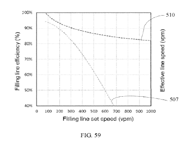
[0079] FIG. 59 is a graph showing efficiency of a filling line versus speed
setting of the filling
line for both untreated vials and vials treated in accordance with various
aspects of this
invention.
[0080] FIG. 60A shows exemplary images of frictive siding and impact
interactions found on
filling lines.
[0081] FIG. 60B shows exemplary images of frictive siding and impact
interactions found on
filling lines.
Detailed Description
[0082] Reference will now be made in detail to embodiments of glass
containers, examples of
which are illustrated in the accompanying drawings. Whenever possible, the
same
reference numerals will be used throughout the drawings to refer to the same
or like parts.
The glass containers described herein have at least two performance attributes
selected
from resistance to delamination, improved strength, and increased damage
resistance. For
example, the glass containers may have a combination of resistance to
delamination and
improved strength; improved strength and increased damage resistance; or
resistance to
delamination and increased damage resistance. In one particular embodiment, a
glass
container may include a body having an inner surface, an outer surface and a
wall
thickness extending between the outer surface and the inner surface. At least
the inner
surface of the body may have a delamination factor less than or equal to 10. A
tenacious
CA 03169162 2022- 8- 23
WO 2021/173321
PCT/US2021/016700
inorganic coating may be positioned around at least a portion of the outer
surface of the
body. The outer surface of the body with the tenacious inorganic coating may
have a
coefficient of friction less than or equal to 0.7. Glass containers with
various
combinations of resistance to delamination, improved strength, and increased
damage
resistance will be described in more detail herein with specific reference to
the appended
drawings.
[0083] In the embodiments of the glass compositions described herein, the
concentration of
constituent components (e.g., SiO2, A1203, B203 and the like) are specified in
mole
percent (mol. %) on an oxide basis, unless otherwise specified.
[0084] The term "substantially free," when used to describe the concentration
and/or absence of
a particular constituent component in a glass composition, means that the
constituent
component is not intentionally added to the glass composition. However, the
glass
composition may contain traces of the constituent component as a contaminant
or tramp
in amounts of less than 0.1 mol. %.
[0085] The term "chemical durability," as used herein, refers to the ability
of the glass
composition to resist degradation upon exposure to specified chemical
conditions.
Specifically, the chemical durability of the glass compositions described
herein may be
assessed according to three established material testing standards. DIN 12116
dated
March 2001 and entitled "Testing of glass¨Resistance to attack by a boiling
aqueous
solution of hydrochloric acid
______________________________________________________ Method of test and
classification"; ISO 695:1991 entitled
"Glass _____________ Resistance to attack by a boiling aqueous solution of
mixed alkali Method of
test and classification"; ISO 720.1985 entitled "Glass ¨Hydrolytic resistance
of glass
16
CA 03169162 2022- 8- 23
WO 2021/173321
PCT/US2021/016700
grains at 121 degrees C.¨Method of test and classification"; and ISO 719:1985
"Glass¨
Hydrolytic resistance of glass grains at 98 degrees C.
______________________________ Method of test and classification."
Each standard and the classifications within each standard are described in
further detail
herein. Alternatively, the chemical durability of a glass composition may be
assessed
according to USP <660> entitled "Surface Glass Test," and or European
Pharmacopeia
3.2.1 entitled "Glass Containers For Pharmaceutical Use" which assess the
durability of
the surface of the glass.
[0086] The term "strain point" and -Tstrain" as used herein, refer to the
temperature at which the
viscosity of the glass is 3 x10¹⁴ poise.
[0087] The term "softening point," as used herein, refers to the temperature
at which the
viscosity of the glass composition is 1x1076 poise.
[0088] Conventional glass containers used for storing pharmaceuticals and/or
other consumable
products may experience damage during filling, packaging, and/or shipping.
Such
damage may be in the form of surface scuffs, abrasions and/or scratches which,
when
sufficiently deep, may result in a through crack or even complete failure of
the glass
container, thereby compromising the contents of the glass package.
[0089] In addition, some conventional glass containers may be susceptible to
delamination,
particularly when the glass container is formed from alkali borosilicate
glasses.
Delamination refers to a phenomenon in which glass particles are released from
the
surface of the glass following a series of leaching, corrosion, and/or
weathering reactions.
In general, the glass particles are silica-rich flakes of glass which
originate from the inner
surface of the package as a result of the leaching of modifier ions into a
solution
17
CA 03169162 2022- 8- 23
WO 2021/173321
PCT/US2021/016700
contained within the package. These flakes may generally be from about 1 nm to
about 2
microns (pm) thick with a width greater than about 501.tm. As these flakes are
primarily
composed of silica, the flakes generally do not further degrade after being
released from
the surface of the glass.
[0090] It has heretofore been hypothesized that delamination is due to phase
separation which
occurs in alkali borosilicate glasses when the glass is exposed to the
elevated
temperatures used for reforming the glass into a container shape.
[0091] However, it is now believed that the delaminati on of the silica-rich
glass flakes from the
inner surfaces of the glass containers is due to the compositional
characteristics of the
glass container immediately following formation. Specifically, the high silica
content of
alkali borosilicate glasses causes the glass to have relatively high melting
and forming
temperatures. However, the alkali and borate components in the glass
composition melt
and/or vaporize at much lower temperatures. In particular, the borate species
in the glass
are highly volatile and evaporate from the surface of the glass at the high
temperatures
necessary to form and reform the glass.
[0092] Specifically, glass stock is reformed into glass containers at high
temperatures and in
direct flames. The high temperatures needed at higher equipment speeds cause
the more
volatile borate species to evaporate from portions of the surface of the
glass. When this
evaporation occurs within the interior volume of the glass container, the
volatilized
borate species are re-deposited in other areas of the glass container surface
causing
compositional heterogeneities in the glass container surface, particularly
with respect to
the near-surface regions of the interior of the glass container (i.e., those
regions at or
18
CA 03169162 2022- 8- 23
WO 2021/173321
PCT/US2021/016700
directly adjacent to the inner surfaces of the glass container). For example,
as one end of
a glass tube is closed to form the bottom or floor of the container, borate
species may
evaporate from the bottom portion of the tube and be re-deposited elsewhere in
the tube.
The evaporation of material from the heel and floor portions of the container
is
particularly pronounced as these areas of the container undergo the most
extensive re-
formation and, as such, are exposed to the highest temperatures. As a result,
the areas of
the container exposed to higher temperatures may have silica-rich surfaces.
Other areas
of the container which are amenable to boron deposition may have a boron-rich
layer at
the surface. Areas amenable to boron deposition which are at a temperature
greater than
the anneal point of the glass composition but less than the hottest
temperature the glass is
subjected to during reformation can lead to boron incorporation on the surface
of the
glass. Solutions contained in the container may leach the boron from the boron-
rich layer.
As the boron-rich layer is leached from the glass, a high silica glass network
(gel)
remains which swells and strains during hydration and eventually spalls from
the surface.
[0093] The glass containers described herein mitigate at least two of the
aforementioned
problems. Specifically, the glass containers have at least two performance
attributes
selected from resistance to delamination, improved strength, and increased
damage
resistance. For example, the glass containers may have a combination of
resistance to
delamination and improved strength; improved strength and increased damage
resistance;
or resistance to delamination and increased damage resistance. Each
performance
attribute and methods for achieving the performance attribute will be
described in further
detail herein.
19
CA 03169162 2022- 8- 23
WO 2021/173321
PCT/US2021/016700
[0094] Referring now to FIGS. 1 and 2, one embodiment of a glass container 100
for storing a
pharmaceutical formulation is schematically depicted in cross section. The
glass
container 100 generally comprises a body 102. The body 102 extends between an
inner
surface 104 and an outer surface 106 and generally encloses an interior volume
108. In
the embodiment of the glass container 100 shown in FIG. 1, the body 102
generally
comprises a wall portion 110 and a floor portion 112. The wall portion 110
transitions
into the floor portion 112 through a heel portion 114. The body 102 has a wall
thickness
Tw which extends between the inner surface 104 to the outer surface 106, as
depicted
in FIG. 1.
[0095] While the glass container 100 is depicted in FIG. 1 as having a
specific shape form (i.e., a
vial), it should be understood that the glass container 100 may have other
shape forms,
including, without limitation, Vacutainers , cartridges, syringes, ampoules,
bottles,
flasks, phials, tubes, beakers, or the like. Further, it should be understood
that the glass
containers described herein may be used for a variety of applications
including, without
limitation, as pharmaceutical packages, beverage containers, or the like.
[0096] Strength
[0097] Still referring to FIGS. 1 and 2, in some embodiments described herein,
the
body 102 includes a compressively stressed layer 202 extending from at least
the outer
surface 106 of the body 102 into the wall thickness Tw to a depth of layer DOL
from the
outer surface 106 of the body 102. The compressively stressed layer 202
generally
increases the strength of the glass container 100 and also improves the damage
tolerance
of the glass container. Specifically, a glass container having a compressively
stressed
CA 03169162 2022- 8- 23
WO 2021/173321
PCT/US2021/016700
layer 202 is generally able to withstand a greater degree of surface damage,
such as
scratches, chips, or the like, without failure compared to a non-strengthened
glass
container as the compressively stressed layer 202 mitigates the propagation of
cracks
from surface damage in the compressively stressed layer 202.
[0098] In the embodiments described herein the depth of layer of the
compressively stressed
layer may be greater than or equal to about 3 !Am. In some embodiments, the
depth of
layer may be greater than 10 [im or even greater than 20 [tm. In some
embodiments, the
depth of layer may be greater than or equal to about 25 tm or even greater
than or equal
to about 30 lam. For example, in some embodiments, the depth of layer may be
greater
than or equal to about 25 wn and up to about 150 pm. In some other
embodiments, the
depth of layer may be greater than or equal to about 30 ium and less than or
equal to about
150 gm. In yet other embodiments, the depth of layer may be greater than or
equal to
about 301..tm and less than or equal to about 80 p.m. In some other
embodiments, the
depth of layer may be greater than or equal to about 35 1..tm and less than or
equal to about
50 [tm.
[0099] The compressively stressed layer 202 generally has a surface
compressive stress (i.e., a
compressive stress as measured at the outer surface 106) of greater than or
equal to 150
MPa. In some embodiments, the surface compressive stress may be greater than
or equal
to 200 MPa, or even greater than or equal to 250 MPa. In some embodiments, the
surface
compressive stress may be greater than or equal to 300 MPa, or even greater
than or
equal to 350 MPa. For example, in some embodiments, the surface compressive
stress
may be greater than or equal to about 300 MPa and less than or equal to about
750 MPa.
21
CA 03169162 2022- 8- 23
WO 2021/173321
PCT/US2021/016700
In some other embodiments, the surface compressive stress may be greater than
or equal
to about 400 MPa and less than or equal to about 700 MPa. In still other
embodiments,
the surface compressive stress may be greater than or equal to about 500 MPa
and less
than or equal to about 650 MPa. The stress in ion-exchanged glass articles can
be
measured with an FSM (Fundamental Stress Meter) instrument. This instrument
couples
light into and out of the birefringent glass surface. The measured
birefringence is then
related to stress through a material constant, the stress-optic or
photoelastic coefficient
(SOC or PLC). Two parameters are obtained: the maximum surface compressive
stress
(CS) and the exchange depth of layer (DOL). Alternatively, the compressive
stress and
depth of layer may be measured using refractive near field stress measurement
techniques.
[00100] While the compressively stressed layer 202 has been shown
and described herein
as extending from the outer surface 106 into the thickness Tw of the body 102,
it should
be understood that, in some embodiments, the body 102 may further comprise a
second
compressively stressed layer which extends from the inner surface 104 into the
thickness
Tw of the body 102. In this embodiment, the depth of layer and surface
compressive
stress of the second compressively stressed layer may mirror those of the
compressively
stressed layer 202 about the centerline of the thickness Tw of the body 102.
[00101] Several different techniques may be utilized to form the
compressively stressed
layer 202 in the body 102 of the glass container 100. For example, in
embodiments where
the body 102 is formed from ion exchangeable glass, the compressively stressed
layer 202 may be formed in the body 102 by ion exchange. In these embodiments,
the
22
CA 03169162 2022- 8- 23
WO 2021/173321
PCT/US2021/016700
compressively stressed layer 202 is formed by placing the glass container in a
bath of
molten salt to facilitate the exchange of relatively large ions in the molten
salt for
relatively smaller ions in the glass. Several different exchange reactions may
be utilized
to achieve the compressively stressed layer 202. In one embodiment, the bath
may
contain molten KNO3 salt while the glass from which the glass container 100 is
formed
contains lithium and/or sodium ions. In this embodiment, the potassium ions in
the bath
are exchanged for the relatively smaller lithium and/or sodium ions in the
glass, thereby
forming the compressively stressed layer 202. In another embodiment, the bath
may
contain NaNO3 salt and the glass from which the glass container 100 is formed
contains
lithium ions. In this embodiment, the sodium ions in the bath are exchanged
for the
relatively smaller lithium ions in the glass, thereby forming the
compressively stressed
layer 202.
[00102] In one specific embodiment, the compressively stressed
layer 202 may be formed
by submerging the glass container in a molten salt bath of 100% KNO3 or, in
the
alternative, a mixture of KNO3 and NaNO3. For example, in one embodiment the
molten
salt bath may include KNO3 with up to about 10% NaNO3. In this embodiment, the
glass
from which the container is formed may include sodium ions and/or lithium
ions. The
temperature of the molten salt bath may be greater than or equal to 350 C.
and less than
or equal to 500 C. In some embodiments, the temperature of the molten salt
bath may be
greater than or equal to 400 C. and less than or equal to 500 C. In still
other
embodiments, the temperature of the molten salt bath may be greater than or
equal to
450 C. and less than or equal to 475 C. The glass container may be held in
the molten
23
CA 03169162 2022- 8- 23
WO 2021/173321
PCT/US2021/016700
salt bath for a time period sufficient to facilitate the exchange of the
relatively large ions
in the salt bath with relatively smaller ions in the glass and thereby achieve
the desired
surface compressive stress and depth of layer. For example, the glass may be
held in the
molten salt bath for a period of time which is greater than or equal to 0.05
hours to less
than or equal to about 20 hours in order to achieve the desired depth of layer
and surface
compressive stress. In some embodiments the glass container may be held in the
molten
salt bath for greater than or equal to 4 hours and less than or equal to about
12 hours. In
other embodiments, the glass container may be held in the molten salt bath for
greater
than or equal to about 5 hours and less than or equal to about 8 hours. In one
exemplary
embodiment, the glass container may be ion exchanged in a molten salt bath
which
comprises 100% KNO3 at a temperature greater than or equal to about 400 C.
and less
than or equal to about 500 C. for a time period greater than or equal to
about 5 hours and
less than or equal to about 8 hours.
[001031 Typically, the ion exchange process is performed at
temperatures more than 150
C. below the strain point (Tstram) of the glass in order to minimize stress
relaxation due to
elevated temperatures. However, in some embodiments, the compressively
stressed
layer 202 is formed in a molten salt bath which is at temperature greater than
the strain
point of the glass. This type of ion exchange strengthening is referred to
herein as "high
temperature ion-exchange strengthening." In high temperature ion-exchange
strengthening, relatively smaller ions in the glass are exchanged with
relatively larger
ions from the molten salt bath, as described above. As the relatively smaller
ions are
exchanged for relatively larger ions at temperatures above the strain point,
the resultant
24
CA 03169162 2022- 8- 23
WO 2021/173321
PCT/US2021/016700
stress is released or "relaxed". However, the replacement of smaller ions in
the glass with
larger ions creates a surface layer in the glass which has a lower coefficient
of thermal
expansion (CTE) than the remainder of the glass. As the glass cools, the CTE
differential
between the surface of the glass and the remainder of the glass creates the
compressively
stressed layer 202. This high temperature ion-exchange technique is
particularly well
suited to strengthening glass articles, such as glass containers, which have
complex
geometries and typically reduces the strengthening process time relative to
typical ion
exchange processes and also enables a greater depth of layer.
[00104] Still referring to FIGS. 1 and 2, in an alternative
embodiment, the compressively
stressed layer 202 may be introduced into the body 102 of the glass container
100 by
thermal tempering. Compressively stressed layers are formed through thermal
tempering
by heating the glass container and differentially cooling the surface of the
glass relative to
the bulk of the glass. Specifically, a glass which is rapidly cooled has a
greater molar
volume (or lower density) than a more slowly cooled glass. Accordingly, if the
surface of
the glass is intentionally rapidly cooled, the surface of the glass will have
a larger volume
and the interior of the glass (i.e., the remainder of the glass below the
outer surface) will
necessarily cool at a slower rate as the heat must escape from the bulk
through the
surface. By creating a continuous gradient in molar volume (or thermal
history/density)
from the outer surface 106 into the wall thickness Tw of the body 102, a
compressively
stressed layer 202 is produced which has a parabolic stress profile (i.e., the
compressive
stress decreases parabolically with increasing distance from the outer surface
106 of the
body 102). Thermal tempering processes are generally faster and less expensive
than ion-
CA 03169162 2022- 8- 23
WO 2021/173321
PCT/US2021/016700
exchange processes. However, the surface compressive stresses due to thermal
tempering
processes are generally lower than the surface compressive stresses due to ion-
exchange
processes. In embodiments where the glass container is thermally tempered, the
resultant
compressively stressed layer extends from the outer surface 106 to a depth of
layer DOL
which is up to 22% of the wall thickness Tw of the glass containers. For
example, in some
embodiments, the DOL may be from about 5% to about 22% of the wall thickness
Tw or
even from about 10% to about 22% of the wall thickness Tw.
[00105] In a typical thermal tempering process, the glass
container 100 is first heated to its
softening point and, thereafter, the outer surface 106 of the body 102 is
rapidly cooled to
below the softening point with a fluid, such as with a gas jet or the like, to
create a
temperature differential between the outer surface 106 of the body 102 and the
remainder
of the body 102, as described above. The temperature differential between the
outer
surface 106 and the remainder of the body produces a compressively stressed
layer 202 extending into the wall thickness Tvv- of the body 102 from the
outer
surface 106. For example, the glass may be initially heated to 50-150 C.
above its
softening point and thereafter rapidly cooled to room temperature by directing
a fluid
onto the glass. The fluid may include, without limitation, air, oil, or oil-
based fluids.
[00106] Referring now to FIGS. 1-3, in another embodiment, the
glass container 100 may
be formed from laminated glass tubing which facilitates the formation of a
compressively
stressed layer 202 in at least the outer surface 106 of the body 102. The
laminated glass
generally comprises a glass core layer 204 and at least one glass cladding
layer 206 a. In
the embodiment of the glass container 100 depicted in FIG. 3, the laminated
glass
26
CA 03169162 2022- 8- 23
WO 2021/173321
PCT/US2021/016700
includes a pair of glass cladding layers 206 a, 206 b. In this embodiment, the
glass core
layer 204 generally comprises a first surface 205 a and a second surface 205 b
which is
opposed to the first surface 205 a. A first glass cladding layer 206 a is
fused to the first
surface 205 a of the glass core layer 204 and a second glass cladding layer
206 h is fused
to the second surface 205 b of the glass core layer 204. The glass cladding
layers 206 a, 206 b are fused to the glass core layer 204 without any
additional materials,
such as adhesives, coating layers or the like, disposed between the glass core
layer 204 and the glass cladding layers 206 a, 206 h.
[00107] In the embodiment shown in FIG. 3, the glass core layer
204 is formed from a
first glass composition having an average core coefficient of thermal
expansion
CTEcore and the glass cladding layers 206 a, 206 b are formed from a second,
different
glass composition which has an average coefficient of thermal expansion
CTEciad. In the
embodiments described herein, CTEcore is not equal to CTEciad such that a
compressive
stress layer is present in at least one of the core layer or the cladding
layer. In some
embodiments, CTEcore is greater than CTEciad which results in the glass
cladding
layers 206 a, 206 b being compressively stressed without being ion exchanged
or
thermally tempered. In some other embodiments, such as when the laminate glass
comprises a single core layer and a single cladding layer, CTEciad may be
greater than
CTEcore which results in the glass core layer being compressively stressed
without being
ion exchanged or thermally tempered.
[00108] The laminated glass tubing from which the glass container
is formed may be
formed as described in U.S. Pat. No. 4,023,953, which is incorporated herein
by
27
CA 03169162 2022- 8- 23
WO 2021/173321
PCT/US2021/016700
reference. In embodiments, the glass forming the glass core layer 204 is
formed from a
glass composition which has an average coefficient of thermal expansion
CTEcoie that is
greater than the average coefficient of thermal expansion CTEciad of either of
the glass
cladding layers 206 a, 206 b. As the glass core layer 204 and the glass
cladding
layers 206 a, 206 b cool, the difference in the average coefficients of
thermal expansion
of the glass core layer 204 and the glass cladding layers 206 a, 206 b cause a
compressively stressed layer to develop in the glass cladding layers 206 a,
206 b. When
the laminated glass is used to form a container, these compressively stressed
layers
extend from the outer surface 106 of the glass container 100 into the wall
thickness
Tw and form the inner surface 104 of the glass container into the wall
thickness Tw. In
some embodiments, the compressively stressed layer may extend from the outer
surface
of the body of the glass container into the wall thickness Tw to a depth of
layer which is
from about 1 pm to about 90% of the wall thickness Tw. In some other
embodiments, the
compressively stressed layer may extend from the outer surface of the body of
the glass
container into the wall thickness Tw to a depth of layer which is from about 1
pm to about
33% of the wall thickness Tw. In still other embodiments, the compressively
stressed
layer may extend from the outer surface of the body of the glass container
into the wall
thickness Tw to a depth of layer which is from about 1 pm to about 10% of the
wall
thickness Tw.
[00109] After the laminated tube is formed, the tube may be formed
into a container shape
using conventional tube conversion techniques.
28
CA 03169162 2022- 8- 23
WO 2021/173321
PCT/US2021/016700
[00110] In some embodiments where the glass container is formed
from laminated glass,
the at least one cladding layer forms the inner surface of the body of the
glass container
such that the at least one glass cladding layer is in direct contact with
product stored in
the glass container. In these embodiments, the at least one cladding layer may
be formed
from a glass composition which is resistant to delamination, as described in
further detail
herein. Accordingly, it should be understood that the at least one cladding
layer may have
a delamination factor of less than or equal to 10, as described in further
detail herein.
[00111] In another alterative embodiment, the glass container may
be strengthened by
applying a coating to the glass body. For example, a coating of an inorganic
material,
such as titania, may be applied to at least a portion of the outer surface of
the glass body
either by soot deposition or by vapor deposition processes. The titania
coating has a
lower coefficient of thermal expansion than the glass it is being deposited
on. As the
coating and the glass cool, the titania shrinks less than the glass and, as a
result, the
surface of the glass body is in tension. In these embodiments, it should be
understood that
the surface compressive stress and depth of layer are measured from the
surface of the
coating rather than the surface of the coated glass body. While the inorganic
coating
material has been described herein as comprising titania, it should be
understood that
other inorganic coating materials with suitably low coefficients of thermal
expansion are
also contemplated. In embodiments, the inorganic coating may have a
coefficient of
friction of less than 0.7 relative to a like coated container. The inorganic
coating may also
be thermally stable at temperatures greater than or equal to 250 C., as
described further
herein.
29
CA 03169162 2022- 8- 23
WO 2021/173321
PCT/US2021/016700
[00112] In another alternative embodiment, the glass body can be
strengthened by the
glass body with a high modulus coating having a coefficient of thermal
expansion equal
to or greater than the underlying glass body. Strengthening is achieved by the
difference
in elastic modulus imparting damage resistance while the difference in thermal
expansion
imparts a compressive stress in the glass surface (balancing tension in the
high modulus
coating). In these embodiments, it should be understood that the surface
compressive
stress and depth of layer are measured from the surface of the glass body
rather than the
surface of the coated glass body. The high modulus makes it difficult for
scratches and
damage to be introduced and the underlying compressive layer prevents
scratches and
flaws from propagating. An exemplary material pairing to demonstrate this
effect is a
sapphire coating on 33 expansion borosilicate glass or a zirconium oxide
coating
deposited on 51 expansion borosilicate glass.
[00113] Based on the foregoing, it should be understood that, in
some embodiments, the
glass containers may include a compressively stressed layer which extends from
at least
the outer surface of the body into the wall thickness of the glass container.
The
compressively stressed layer improves the mechanical strength of the glass
container
relative to a glass container which does not include a compressively stressed
layer. The
compressively stressed layer also improves the damage tolerance of the glass
container
such that the glass container is able to withstand greater surface damage
(i.e., scratches,
chips, etc., which extend deeper into the wall thickness of the glass
container) without
failure relative to a glass container which does not include a compressively
stressed layer.
Further, it should also be understood that, in these embodiments, the
compressively
CA 03169162 2022- 8- 23
WO 2021/173321
PCT/US2021/016700
stressed layer may be formed in the glass container by ion exchange, by
thermal
tempering, by forming the glass container from laminated glass, or by applying
a coating
to the glass body. In some embodiments, the compressively stressed layer may
be formed
by a combination of these techniques.
[00114] Delamination Resistance
[00115] In some embodiments, the glass containers 100 may also
resist delamination
following long term exposure to certain chemical compositions stored in the
container.
As noted above, delamination may result in the release of silica-rich glass
flakes into a
solution contained within the glass container after extended exposure to the
solution.
Accordingly, the resistance to delamination may be characterized by the number
of glass
particulates present in a solution contained within the glass container after
exposure to
the solution under specific conditions. In order to assess the long-term
resistance of the
glass container to delamination, an accelerated delamination test is utilized.
The test may
be performed on both ion-exchanged and non-ion-exchanged glass containers. The
test
consists of washing the glass container at room temperature for 1 minute and
depyrogenating the container at about 320 C. for 1 hour. Thereafter a
solution of 20 mM
glycine with a pH of 10 in water is placed in the glass container to 80-90%
fill, the glass
container is closed, and the glass container is rapidly heated to 100 C. and
then heated
from 100 C. to 121 C. at a ramp rate of 1 deg/min at a pressure of 2
atmospheres. The
glass container and solution are held at this temperature for 60 minutes,
cooled to room
temperature at a rate of 0.5 deg./min and the heating cycle and hold are
repeated. The
glass container is then heated to 50 C. and held for ten or more days for
elevated
31
CA 03169162 2022- 8- 23
WO 2021/173321
PCT/US2021/016700
temperature conditioning. After heating, the glass container is dropped from a
distance of
at least 18" onto a firm surface, such as a laminated tile floor, to dislodge
any flakes or
particles that are weakly adhered to the inner surface of the glass container.
The distance
of the drop may be scaled appropriately to prevent larger sized vials from
fracturing on
impact.
[00116] Thereafter, the solution contained in the glass container is
analyzed to determine
the number of glass particles present per liter of solution. Specifically, the
solution from
the glass container is directly poured onto the center of a Millipore Isopore
Membrane
filter (Millipore #ATTP02500 held in an assembly with parts #AP1002500 and
#M000025A0) attached to vacuum suction to draw the solution through the filter
within
10-15 seconds for 5 mL. Thereafter, another 5 mL of water is used as a rinse
to remove
buffer residue from the filter media. Particulate flakes are then counted by
differential
interference contrast microscopy (DIC) in the reflection mode as described in
"Differential interference contrast (DIC) microscopy and modulation contrast
microscopy" from Fundamentals of light microscopy and digital imaging. New
York:
Wiley-Liss, pp 153-168. The field of view is set to approximately 1.5 mmx1.5
mm and
particles larger than 50 p.m are counted manually. There are 9 such
measurements made
in the center of each filter membrane in a 3><3 pattern with no overlap
between images. If
larger areas of the filter media are analyzed, results can be normalized to
equivalent area
(i.e., 20.25 mm2). The images collected from the optical microscope are
examined with
an image analysis program (Media Cybernetic's ImagePro Plus version 6.1) to
measure
and count the number of glass flakes present. This is accomplished as follows:
all of the
32
CA 03169162 2022- 8- 23
WO 2021/173321
PCT/US2021/016700
features within the image that appeared darker than the background by simple
grayscale
segmentation are highlighted; the length, width, area, and perimeter of all of
the
highlighted features that have a length greater than 25 micrometers are then
measured;
any obviously non-glass particles are then removed from the data; the
measurement data
is then exported into a spreadsheet. Then, all of the features greater than 25
micrometers
in length and brighter than the background are extracted and measured; the
length, width,
area, perimeter, and X-Y aspect ratio of all of the highlighted features that
have a length
greater than 25 micrometers are measured; any obviously non-glass particles
are removed
from the data; and the measurement data is appended to the previously exported
data in
the spreadsheet. The data within the spreadsheet is then sorted by feature
length and
broken into bins according to size. The reported results are for features
greater than 50
micrometers in length. Each of these groups is then counted and the counts
reported for
each of the samples.
[001171 A minimum of 100 mL of solution is tested. As such, the
solution from a plurality
of small containers may be pooled to bring the total amount of solution to 100
mL. For
containers having a volume greater than 10 mL, the test is repeated for a
trial of 10
containers formed from the same glass composition under the same processing
conditions
and the result of the particle count is averaged for the 10 containers to
determine an
average particle count. Alternatively, in the case of small containers, the
test is repeated
for a trial of 10 vials, each of which is analyzed and the particle count
averaged over the
multiple trials to determine an average particle count per trial. Averaging
the particle
count over multiple containers accounts for potential variations in the
delamination
33
CA 03169162 2022- 8- 23
WO 2021/173321
PCT/US2021/016700
behavior of individual containers. Table 1 summarizes some non-limiting
examples of
sample volumes and numbers of containers for testing:
34
CA 03169162 2022- 8- 23
WO 2021/173321
PCT/US2021/016700
Table 1: Table of Exemplary Test Specimens
Nominal Vial Max Minimum Number of Number of
Total
Vial Volume Solution Vials In a Trials
Solution
Capacity (mL) Per Vial Trial
Tested
(mL) (mL)
(mL)
2.0 4.0 3.2 10 4 128
3.5 7.0 5.6 10 2 112
4.0 6.0 4.8 10 3 144
5.0 10.0 8.0 10 2 160
6.0 10.0 8.0 10 2 160
8.0 11.5 9.2 10 2 184
10.0 13.5 10.8 10 1 108
20.0 26.0 20.8 10 1 208
30.0 37.5 30.0 10 1 300
50.0 63.0 50.4 10 1 504
[00118] It should be understood that the aforementioned test is
used to identify particles
which are shed from the interior wall(s) of the glass container due to
delamination and
not tramp particles present in the container from forming processes or
particles which
precipitate from the solution enclosed in the glass container as a result of
reactions
between the solution and the glass. Specifically, delamination particles may
be
differentiated from tramp glass particles based on the aspect ratio of the
particle (i.e., the
ratio of the maximum length of the particle to the thickness of the particle,
or a ratio of
CA 03169162 2022- 8- 23
WO 2021/173321
PCT/US2021/016700
the maximum and minimum dimensions). Delamination produces particulate flakes
or
lamellae which are irregularly shaped and typically have a maximum length
greater than
about 50]..tm but often greater than about 200 p.m. The thickness of the
flakes is usually
greater than about 100 nm and may be as large as about 1 [tm. Thus, the
minimum aspect
ratio of the flakes is typically greater than about 50. The aspect ratio may
be greater than
about 100 and sometimes greater than about 1000. In contrast, tramp glass
particles will
generally have a low aspect ratio which is less than about 3. Accordingly,
particles
resulting from delamination may be differentiated from tramp particles based
on aspect
ratio during observation with the microscope. Other common non-glass particles
include
hairs, fibers, metal particles, plastic particles, and other contaminants and
are thus
excluded during inspection. Validation of the results can be accomplished by
evaluating
interior regions of the tested containers. Upon observation, evidence of skin
corrosion/pitting/flake removal, as described in "Nondestructive Detection of
Glass Vial
Inner Surface Morphology with Differential Interference Contrast Microscopy-
from
Journal of Pharmaceutical Sciences 101(4), 2012, pages 1378-1384, is noted.
[00119] The number of particles present following accelerated
delamination testing may
be utilized to establish a delamination factor for the set of vials tested.
Trials of glass
containers which average less than 10 glass particles with a minimum length of
about 50
[tm and an aspect ratio of greater than about 50 per trial following
accelerated
delamination testing are considered to have a delamination factor of 10.
Trials of glass
containers which average less than 9 glass particles with a minimum length of
about 50
lam and an aspect ratio of greater than about 50 per trial following
accelerated
36
CA 03169162 2022- 8- 23
WO 2021/173321
PCT/US2021/016700
delamination testing are considered to have a delamination factor of 9. Trials
of glass
containers which average less than 8 glass particles with a minimum length of
about 50
p.m and an aspect ratio of greater than about 50 per trial following
accelerated
delamination testing are considered to have a delamination factor of S. Trials
of glass
containers which average less than 7 glass particles with a minimum length of
about 50
pm and an aspect ratio of greater than about 50 per trial following
accelerated
delamination testing are considered to have a delamination factor of 7. Trials
of glass
containers which average less than 6 glass particles with a minimum length of
about 50
pm and an aspect ratio of greater than about 50 per trial following
accelerated
delamination testing are considered to have a delamination factor of 6. Trials
of glass
containers which average less than 5 glass particles with a minimum length of
about 50
pm and an aspect ratio of greater than about 50 per trial following
accelerated
delamination testing are considered to have a delamination factor of 5. Trials
of glass
containers which average less than 4 glass particles with a minimum length of
about 50
pm and an aspect ratio of greater than about 50 per trial following
accelerated
delamination testing are considered to have a delamination factor of 4. Trials
of glass
containers which average less than 3 glass particles with a minimum length of
about 50
pm and an aspect ratio of greater than about 50 per trial following
accelerated
delamination testing are considered to have a delamination factor of 3. Trials
of glass
containers which average less than 2 glass particles with a minimum length of
about 50
pm and an aspect ratio of greater than about 50 per trial following
accelerated
delamination testing are considered to have a delamination factor of 2. Trials
of glass
37
CA 03169162 2022- 8- 23
WO 2021/173321
PCT/US2021/016700
containers which average less than 1 glass particle with a minimum length of
about 50
pm and an aspect ratio of greater than about 50 per trial following
accelerated
delamination testing are considered to have a delamination factor of 1. Trials
of glass
containers which have 0 glass particles with a minimum length of about 50 p.m
and an
aspect ratio of greater than about 50 per trial following accelerated
delamination testing
are considered to have a delamination factor of 0. Accordingly, it should be
understood
that the lower the delamination factor, the better the resistance of the glass
container to
delamination. In some embodiments described herein, at least the inner surface
of the
body of the glass container has a delamination factor of 10 or lower (e.g., a
delamination
factor of 3, 2, 1 or 0). In some other embodiments, the entire body of the
glass container,
including both the inner surface and the outer surface, has a delamination
factor of 10 or
lower (e.g., a delamination factor of 3, 2, 1, or 0).
[00120]
In some embodiments, a glass container having a delamination factor of 10
or
lower may be obtained by forming the glass container with a barrier coating on
the inner
surface of the body such that the barrier coating is the inner surface of the
body.
Referring to FIG. 5 by way of example, a glass container 100 with a barrier
coating 131 deposited on at least a portion of the inner surface 104 of the
body 102 is
schematically depicted. The barrier coating 131 does not delaminate or
otherwise degrade
and prevents product stored in the interior volume 108 of the glass container
100, such as
pharmaceutical compositions or the like, from contacting the inner surface 104
of the
body 102 thereby mitigating delamination of the glass container. The barrier
coating is
38
CA 03169162 2022- 8- 23
WO 2021/173321
PCT/US2021/016700
generally non-permeable to aqueous solutions, is insoluble in water, and
hydrolytically
stable.
[00121] In some embodiments described herein, the barrier coating
131 is a tenacious
inorganic coating that is permanently adhered to the inner surface 104 of the
glass
container 100. The barrier coating 131 may be a metal nitride coating, a metal
oxide
coating, a metal sulfide coating, Si02, diamond-like carbide, graphenes or a
carbide
coating. For example, in some embodiments, the tenacious inorganic coating may
be
formed from at least one metal oxide such as A1203, Ti02, Zr02, SnO, SiO2,
Ta205,
Nb2O5, Cr203, V205, ZnO, or Hf02. In some other embodiments, the tenacious
inorganic
coating may be formed from a combination of two or more of metal oxides such
as
A1203, Ti02, Zr02, SnO, Si02, Ta205, Nb205, Cr203, V205 ,ZnO, or Hf02. In some
other
embodiments, the barrier coating 131 may comprise a first layer of a first
metal oxide
deposited on the inner surface of the glass container and a second layer of a
second metal
oxide deposited over the first layer. In these embodiments, the barrier
coating 131 may be
deposited using a variety of deposition techniques including, without
limitation, atomic
layer deposition, chemical vapor deposition, physical vapor deposition, and
the like.
Alternatively, the barrier coating may be applied with one or more liquid
application
techniques such as dip coating, spray coating or plasma coating. Spray coating
techniques
may include high volume low pressure (HVLP) and low volume low pressure (LVLP)
spray coating, electrostatic spray coating, airless spray coating, ultrasonic
atomization
with airless spray coating, aerosol jet coating, and ink jet coating. Plasma
coating
39
CA 03169162 2022- 8- 23
WO 2021/173321
PCT/US2021/016700
techniques may include standard primary and secondary plasma coating,
microwave
assisted plasma coating, and atmospheric plasma coating and the like.
[00122] While embodiments of the barrier coating 131 have been
described herein as
comprising inorganic materials, it should be understood that, in some
embodiments, the
barrier coating 131 may be an organic coating. For example, in embodiments
where the
barrier coating 131 is an organic coating, the organic coating may comprise
polybenzimidazoles, polybisoxazoles, polybisthiazoles, polyetherimides,
polyquinolines,
polythiophenes, phenyl ene sulfides, polysulfones, polycyanurates, parylenes,
fluorinated
polyolefins including polytetrafluorethylenes and other fluoro-substituted
polyolefins,
perfluoroalkoxy polymers, polyether ether ketones (PEEK), polyamides, epoxies,
polyphenolics, polyurethane acrylates, cyclic olefin copolymer and cyclic
olefin
polymers, polyolefins including polyethylenes, oxidized polyethylenes,
polypropylenes,
polyethylene/propylene copolymers, polyethylene/vinyl acetate copolymers,
polyvinylchloride, polyacrylates, polymethacrylates, polystyrenes,
polyterpenes,
polyanhydrides, polymaleicanhydrides, polyformaldehydes, polyacetals and
copolymers
of polyacetals, polysiloxanes of dimethyl or diphenyl or methyl/phenyl
mixtures,
perfluorinated siloxanes and other substituted siloxanes, polyimides,
polycarbonates,
polyesters, parafins and waxes, or various combinations thereof In some
embodiments,
the organic coating used as a barrier coating 131 may include polysiloxanes of
dimethyl,
diphenyl, or methyl/phenyl mixtures. Alternatively, the organic coating may be
a
polycarbonate or polyethylene terephthalate. In some embodiments, the barrier
CA 03169162 2022- 8- 23
WO 2021/173321
PCT/US2021/016700
coating 131 may be formed from a layered structure comprising one or more of
the
aforementioned polymers and/or copolymers.
[00123] Barrier coatings may be utilized in conjunction with glass
containers formed from
any glass composition. However, barrier coatings are particularly well suited
for use with
glass containers formed from glass compositions which do not exhibit a
resistance to
delamination upon formation into a glass container. Such glass compositions
may
include, without limitation, those glass compositions designated as Type I
Class A, Type
Class B, and Type IT glass compositions according to A STM Standard E438-92
(2011)
entitled "Standard Specification for Glasses in Laboratory Apparatus." Such
glass
compositions may have the requisite chemical durability under the ASTM
Standard, but
do not exhibit resistance to delamination. For example, Table 2 below lists
several non-
limiting examples of Type I Class B glass compositions which do not exhibit a
resistance
to delamination. As such, barrier coatings as described herein may be used on
at least the
inner surfaces of containers formed from these compositions such that the
container has a
delamination factor of 10 or lower.
41
CA 03169162 2022- 8- 23
WO 2021/173321 PCT/US2021/016700
Table 2: Exemplary Type I, Class B Glass Compositions
Example 1 Example 2
Example 3
(wt. %) (wt. %)
(wt. %)
SO, 71.70 74.6
70.1
Atz:C: 6.61 5.56
3.41
11.50 10.9
12.4
NaM 6.40 6.93
5.91
L Q 2.35 0.04
2.8
Me: 0.300 0.057
0.009
0.56 1.47
1.03
9,p,0 0.004 0.004
0.026
3a.0 0.003 0.003 2.73
;Zi-10 0.000 0.000
0.97
0.092 0.046
0.049
Tiga 0.028 0.018
0.027
0.033 0.032
0.038
0.0003 0.0828
0.0003
0.0450 0.0020
0.0750
[00124] In some alternative embodiments, a glass container having
a delamination factor
of 10 or lower is achieved by forming the glass container such that the glass
container has
homogenous compositional characteristics which, in turn, reduces the
susceptibility of the
42
CA 03169162 2022- 8- 23
WO 2021/173321
PCT/US2021/016700
glass container to delamination, as described in copending U.S. patent
application Ser.
No. 13/912,457 filed Jun. 7, 2013 entitled "Delamination Resistant Glass
Containers" and
assigned to Corning Incorporated. Specifically, it is believed that
delamination of the
glass container may be due, at least in part, to heterogeneities in the glass
composition in
at least the interior of the glass container, as described above. Minimizing
such
compositional heterogeneities produces a glass container which has a
delamination factor
of 10 or lower.
[00125] Referring now to FIGS 1 and 6, in some embodiments, the
glass containers
described herein have a homogenous composition through the thickness of the
glass
body 102 in each of the wall, heel, and floor portions such that at least the
inner
surface 104 of the body has a delamination factor of 10 or lower.
Specifically, FIG.
6 schematically depicts a partial cross section of a wall portion 110 of the
glass
container 100. The glass body 102 of the glass container 100 has an interior
region 120 which extends from about 10 nm below the inner surface 104 of the
glass
container 100 (indicated in FIG. 6 as DLO into the thickness of the wall
portion 110 to a
depth DLR2 from the inner surface 104 of the glass container. The interior
region
extending from about 10 nm below the inner surface 104 is differentiated from
the
composition in the initial 5-10 nm below the surface due to experimental
artifacts. At the
start of a dynamic secondary ion mass spectroscopy (DSIMS) analysis to
determine the
composition of the glass, the initial 5-10 nm is not included in the analysis
because of
three concerns: variable sputtering rate of ions from the surface as a result
of adventitious
carbon, establishment of a steady state charge in part due to the variable
sputtering rate,
43
CA 03169162 2022- 8- 23
WO 2021/173321
PCT/US2021/016700
and mixing of species while establishing a steady state sputtering condition.
As a result,
the first two data points of the analysis are excluded. Accordingly, it should
be
understood that the interior region 120 has a thickness TLR which is equal to
DLR2-DLR1.
The glass composition within the interior region has a persistent layer
homogeneity
which, in conjunction with the thickness TLR of the interior region, is
sufficient to prevent
delamination of the glass body following long term exposure to a solution
contained in
the interior volume of the glass container. In some embodiments, the thickness
TLR is at
least about 100 nm. In some embodiments, the thickness TLR is at least about
150 nm. In
some other embodiments, the thickness TLR is at least about 200 nm or even
about 250
nm. In some other embodiments, the thickness TLR is at least about 300 nm or
even about
350 nm. In yet other embodiments, the thickness TLR is at least about 500 nm.
In some
embodiments, the interior region 120 may extend to a thickness TLR of at least
about 1 nm
or even at least about 2 nm.
[001261 While the interior region is described herein as extending
from 10 nm below the
inner surface 104 of the glass container 100 into the thickness of the wall
portion 110 to a
depth DLR2 from the inner surface 104 of the glass container, it should be
understood that
other embodiments are possible. For example, it is hypothesized that, despite
the
experimental artifacts noted above, the interior region with the persistent
layer
homogeneity may actually extend from the inner surface 104 of the glass
container 100 into the thickness of the wall portion. Accordingly, in some
embodiments,
the thickness TLR may extend from the inner surface 104 to the depth DLR2 . In
these
embodiments, the thickness TLR may be at least about 100 nm. In some
embodiments, the
44
CA 03169162 2022- 8- 23
WO 2021/173321
PCT/US2021/016700
thickness TLR is at least about 150 nm. In some other embodiments, the
thickness TLR is at
least about 200 nm or even about 250 nm. In some other embodiments, the
thickness
TLR is at least about 300 nm or even about 350 nm. In yet other embodiments,
the
thickness TLR is at least about 500 nm. In some embodiments, the interior
region 120 may
extend to a thickness TLR of at least about 1 pm or even at least about 2 pin.
[00127] In embodiments where the glass container is formed such
that the glass container
has a persistent layer homogeneity, the phrase "persistent layer homogeneity"
means that
the concentration of the constituent components (e.g., SiO2, A1203, Na2O,
etc.) of the
glass composition in the interior region do not vary from the concentration of
the same
constituent components at the midpoint of a thickness of the glass layer which
contains
the interior region by an amount which would result in delamination of the
glass body
upon long term exposure to a solution contained within the glass container.
For example,
in embodiments where the glass container is formed from a single glass
composition, the
glass body contains a single layer of glass and the concentration of
constituent
components in the interior region is compared to the concentration of the same
components at a point along the midpoint line MP which evenly bisects the
glass body
between the inner surface 104 and the outer surface 106 to determine if a
persistent layer
homogeneity is present. However, in embodiments where the glass container is
formed
from a laminated glass in which a glass cladding layer of the laminated glass
forms the
interior surface of the glass container, the concentration of constituent
components in the
interior region is compared to the concentration of the same components at a
point along
the midpoint line which evenly bisects the glass cladding layer that forms the
interior
CA 03169162 2022- 8- 23
WO 2021/173321
PCT/US2021/016700
surface of the glass container. In the embodiments described herein, the
persistent layer
homogeneity in the interior region of the glass body is such that an extrema
(i.e., the
minimum or maximum) of a layer concentration of each of the constituent
components of
the glass composition in the interior region 120 is greater than or equal to
about 80% and
less than or equal to about 120% of the same constituent component at a
midpoint of the
glass layer which contains the interior region 120. The persistent layer
homogeneity, as
used herein, refers to the state of the glass container when the glass
container is in as-
formed condition or following one or more surface treatments applied to at
least the
interior surface of the glass container, such as etching or the like. In other
embodiments,
the persistent layer homogeneity in the interior region of the glass body is
such that the
extrema of the layer concentration of each of the constituent components of
the glass
composition in the interior region 120 is greater than or equal to about 90%
and less than
or equal to about 110% of the same constituent component at the midpoint of
the
thickness of the glass layer which contains the interior region 120. In still
other
embodiments, the persistent layer homogeneity in the interior region of the
glass body is
such that the extrema of the layer concentration of each of the constituent
components of
the glass composition in the interior region 120 is greater than or equal to
about 92% and
less than or equal to about 108% of the same constituent component at the
midpoint of
the thickness of the glass of the glass layer which contains the interior
region 120. In
some embodiments, the persistent layer homogeneity is exclusive of constituent
components of the glass composition which are present in an amount less than
about 2
mol. %.
46
CA 03169162 2022- 8- 23
WO 2021/173321
PCT/US2021/016700
[00128] The term "as-formed condition," as used herein, refers to
the composition of the
glass container 100 after the glass container has been formed from glass stock
but prior to
the container being exposed to any additional processing steps, such as ion-
exchange
strengthening, coating, ammonium sulfate treatment or the like. In some
embodiments,
the term "as-formed condition" includes the composition of the glass container
100 after
the glass container has been formed and exposed to an etching treatment to
selectively
remove all or a portion of at least the interior surface of the glass
container. In the
embodiments described herein, the layer concentration of the constituent
components in
the glass composition is determined by collecting a composition sample through
the
thickness of the glass body in the area of interest using dynamic secondary
ion mass
spectroscopy (DSIIVIS). In the embodiments described herein, the composition
profile is
sampled from areas of the inner surface 104 of the glass body 102. The sampled
areas
have a maximum area of 1 mm2. This technique yields a compositional profile of
the
species in the glass as a function of depth from the inner surface of the
glass body for the
sampled area.
[00129] Forming the glass container with a persistent layer
homogeneity as described
above, generally improves the resistance of the glass container to
delamination.
Specifically, providing an interior region which is homogenous in composition
(i.e., the
extrema of the concentration of the constituent components in the interior
region is within
+/-20% of the same constituent components at the midpoint of the thickness of
the glass
layer which contains the interior region) avoids the localized concentration
of constituent
components of the glass composition which may be susceptible to leaching
which, in
47
CA 03169162 2022- 8- 23
WO 2021/173321
PCT/US2021/016700
turn, mitigates the loss of glass particles from the inner surface of the
glass container in
the event that these constituent components are leached from the glass
surface.
[00130] As noted herein, the container with the persistent layer
homogeneity in as-formed
condition is free from coatings, including inorganic and/or organic coatings
applied to the
inner surface of the glass body. Accordingly, it should be understood that the
body of the
glass container is formed from a substantially unitary composition which
extends from
the inner surface of the body to a depth of at least 250 nm or even at least
300 nm. The
term "unitary composition" refers to the fact that the glass from which the
portion of the
body extending from the inner surface into the thickness of the body to a
depth of at least
250 nm or even at least 300 nm is formed is a single composition of material
as compared
to a coating material applied to another material of either the same or
different
composition. For example, in some embodiments, the body of the container may
be
constructed from a single glass composition. In other embodiments, the body of
the
container may be constructed from a laminated glass such that the inner
surface of the
body has a unitary composition which extends from the inner surface to a depth
of at least
250 nm or even at least 300 nm. The glass container may include an interior
region which
extends from either the inner surface or from 10 nm below the inner surface to
a depth of
at least 100 nm, as noted above. This interior region may have a persistent
layer
homogeneity.
[00131] Referring now to FIGS. 1 and 7, in some embodiments, the
glass containers
described herein may also have a homogenous surface composition over the inner
surface 104 of the body 102 such that at least the inner surface 104 of the
body 102,
48
CA 03169162 2022- 8- 23
WO 2021/173321
PCT/US2021/016700
including in the wall, heel, and floor portions, has a delamination factor of
10 or less
when the glass container is in as-formed condition. FIG. 7 schematically
depicts a partial
cross section of a wall portion 110 of the glass container 100. The glass
container 100 has
a surface region 130 which extends over the entire inner surface of the glass
container.
The surface region 130 has a depth DSR which extends from the inner surface
104 of the
glass container 100 into a thickness of the glass body towards the exterior
surface.
Accordingly, it should be understood that the surface region 130 has a
thickness
TSR which is equal to the depth DSR. In some embodiments, the surface region
extends to
a depth DSR of at least about 10 nm from the inner surface 104 of the glass
container 100.
In some other embodiments, the surface region 130 may extend to a depth DSR of
at least
about 50 nm. In some other embodiments, the surface region 130 may extend to a
depth
DSR from about 10 nm to about 50 nm. Accordingly, it should be understood that
the
surface region 1130 extends to a shallower depth than the interior region 120.
The glass
composition of the surface region has a persistent surface homogeneity which,
in
conjunction with the depth DSR of the interior region, is sufficient to
prevent delamination
of the glass body following long term exposure to a solution contained in the
interior
volume of the glass container.
[00132] In the embodiments described herein, the phrase
"persistent surface homogeneity"
means that the concentration of the constituent components (e.g., SiO2, A1203,
Na2O,
etc.) of the glass composition at a discrete point in the surface region do
not vary from the
concentration of the same constituent components at any second discrete point
in the
surface region by an amount which would result in delamination of the glass
body upon
49
CA 03169162 2022- 8- 23
WO 2021/173321
PCT/U52021/016700
long term exposure to a solution contained within the glass container. In the
embodiments
described herein, the persistent surface homogeneity in the surface region is
such that, for
a discrete point on the inner surface 104 of the glass container, the extrema
(i.e., the
minimum or maximum) of the surface concentration of each of the constituent
components in the surface region 130 at a discrete point is greater than or
equal to about
70% and less than or equal to about 130% of the same constituent components in
the
surface region 130 at any second discrete point on the inner surface 104 of
the glass
container 100 when the glass container 100 is in as-formed condition. For
example, FIG.
7 depicts three discrete points (A, B, and C) on the inner surface 104 of the
wall
portion 110. Each point is separated from an adjacent point by at least about
3 mm. The
extrema of the surface concentration of each of the constituent components in
the surface
region 130 at point -A" is greater than or equal to about 70% and less than or
equal to
about 130% of the same constituent components in the surface region 130 at
points "B-
and "C-. When referring to the heel portion of the container, the discrete
points may be
approximately centered at the apex of the heel with adjacent points located at
least 3 mm
from the apex of the heel along the floor portion of the container and along
the wall
portion of the container, the distance between the points being limited by the
radius of the
container and the height of the sidewall (i.e., the point where the sidewall
transitions to
the shoulder of the container).
[00133] In some embodiments, the persistent surface homogeneity in
the surface region is
such that the extrema of the surface concentration of each of the constituent
components
of the glass composition in the surface region 130 for any discrete point on
the inner
CA 03169162 2022- 8- 23
WO 2021/173321
PCT/US2021/016700
surface 104 of the glass container 100 is greater than or equal to about 75%
and less than
or equal to about 125% of the same constituent component in the surface region
130 at
any second discrete point on the inner surface 104 of the glass container 100.
In some
other embodiments, the persistent surface homogeneity in the surface region is
such that
the extrema of the surface concentration of each of the constituent components
of the
glass composition in the surface region 130 for any discrete point on the
inner
surface 104 of the glass container 100 is greater than or equal to about 80%
and less than
or equal to about 120% of the same constituent component in the surface region
130 at
any second discrete point on the inner surface 104 of the glass container 100.
In still other
embodiments, the persistent surface homogeneity in the surface region is such
that the
extrema of the surface concentration of each of the constituent components of
the glass
composition in the surface region 130 for any discrete point on the inner
surface 104 of
the glass container 100 is greater than or equal to about 85% and less than or
equal to
about 115% of the same constituent component in the surface region 130 at any
second
discrete point on the inner surface 104 of the glass container 100. In the
embodiments
described herein, the surface concentration of the constituent components of
the glass
composition in the surface region is measured by x-ray photoelectron
spectroscopy. In
some embodiments, the persistent surface homogeneity in the surface region is
exclusive
of constituent components of the glass composition which are present in an
amount less
than about 2 mol. %.
[001341 The homogeneity of the surface concentration of the glass
constituent components
in the surface region 130 is generally an indication of the propensity of the
glass
51
CA 03169162 2022- 8- 23
WO 2021/173321
PCT/U52021/016700
composition to delaminate and shed glass particles from the inner surface 104
of the glass
container 100.
[00135] When the glass composition has a persistent surface
homogeneity in the surface
region 130 (i.e., when the extrema of the surface concentration of the glass
constituent
components in the surface region 130 at a discrete point on the inner surface
104 are
within +/-30% of the same constituent components in the surface region 130 at
any
second discrete point on the inner surface 104), the glass composition has
improved
resistance to delamination.
[00136] Glass containers having persistent layer homogeneity
and/or persistent surface
homogeneity may be achieved using various techniques. For example, in some
embodiments, at least the inner surface 104 of the body 102 of the glass
container is
etched which produces a glass container having a persistent layer homogeneity
and/or a
persistent surface homogeneity such that at least the inner surface of the
glass container
has a delamination factor of 10 or less. Specifically, compositional
variations in the glass
due to volatilization of species from the glass and subsequent re-deposition
of the
volatized species during container formation, as described above, is believed
to be one
mechanism that leads to delamination. The thin skin of volatized and re-
deposited species
on the inner surface of the glass container is compositionally heterogeneous
and
hydrolytically weak such that alkali and boron species are quickly depleted
from the skin
during exposure to pharmaceutical compositions. This behavior leaves behind a
silica
rich layer with a high surface area. Exposure of this silica rich layer to a
pharmaceutical
composition causes the layer to swell and, ultimately, flake off (i.e.,
delaminate) from the
52
CA 03169162 2022- 8- 23
WO 2021/173321
PCT/U52021/016700
inner surface of the body. However, etching the inner surface of the body of
the glass
container removes this thin skin layer and imparts a persistent layer
homogeneity and/or
persistent surface homogeneity to at least the inner surface of the body of
the glass
container.
[00137] In some embodiments described herein, the body of the glass
container is etched
to remove a layer of glass material from the inner surface of the glass body.
The etch is
sufficient to remove the thin skin layer of volatized and re-deposited species
and thereby
provide a persistent layer homogeneity and/or a persistent surface homogeneity
to at least
the inner surface of the body of the glass container such that at least the
inner surface of
the glass body has a delamination factor of 10 or less. For example, in some
embodiments, the body of the glass container is etched to remove glass
material from the
inner surface of the glass body to a depth of 1 um or even 1.5 um. In some
other
embodiments, the body of the glass container may be etched to remove glass
material to a
depth greater than 1.5 um, including, without limitation, 2 pm, 3 um or even 5
um. In
these embodiments, at least the interior surface of the glass container may be
formed
from glass compositions which meet the criteria for Type I, Class A (Type IA)
or Type I,
Class B (Type 113) glasses under ASTM Standard E438-92 (2011) entitled
"Standard
Specification for Glasses in Laboratory Apparatus". Borosilicate glasses meet
the Type I
(A or B) criteria and are routinely used for pharmaceutical packaging.
Examples of
borosilicate glass include, without limitation, Corning Pyrex 7740, 7800,
Wheaton
180, 200, and 400, Schott Duran , Schott Fiolax , KIMAX N-51A, Gerresheimer
GX-51 Flint and others.
53
CA 03169162 2022- 8- 23
WO 2021/173321
PCT/U52021/016700
[00138] In one embodiment, etching may be accomplished by exposing
the inner surface
of the glass container to an acid solution, or a combination of acid
solutions. The acid
solutions may include, without limitation, sulfuric acid, nitric acid,
hydrochloric acid,
hydrofluoric acid, hydrobromic acid, and phosphoric acid. For example, the
acid solution
may include a mixture of 1.5 M hydrofluoric acid with 0.9 M sulfuric acid.
These acid
solutions effectively remove the thin skin layer of volatized and re-deposited
organic
solution without leaving a depleted "leach layer" on the inner surface of the
glass
container. Alternatively, etching may be accomplished by exposing the inner
surface of
the glass container to a base solution or a combination of base solutions.
Suitable base
solutions include, for example, sodium hydroxide, potassium hydroxide,
ammonium
hydroxide, or combinations thereof. Alternatively, etching may be accomplished
by
sequentially acid solutions followed by base solutions or vice-versa.
[00139] While one specific etching treatment is described herein,
it should be understood
that other etching treatments may also be used. For example, the etching
treatments
disclosed in U.S. Pat. No. 2,106,744, U.S. Patent Publication No.
2011/0165393, U.S.
Patent Publication No. 2013/0122306, and U.S. Patent Publication No.
2012/0282449
may also be used to etch at least the interior surface of the glass container.
[00140] In still other embodiments, glass containers may be
provided with a persistent
layer homogeneity and/or a persistent surface homogeneity by forming the glass
containers from glass compositions in which the constituent components of the
glass
composition form species with relatively low vapor pressures (i.e., species
with a low
volatility) at the temperatures required to reform the glass containers from
glass stock
54
CA 03169162 2022- 8- 23
WO 2021/173321
PCT/US2021/016700
into the desired container shape. Because these constituent components form
species with
relatively low vapor pressures at the reforming temperatures, the constituent
components
are less likely to volatilize and evaporate from the surfaces of the glass,
thereby forming a
glass container with a compositionally homogenous surface over the inner
surface of the
glass container and through the thickness of the glass container.
[00141] Certain constituent components of the glass composition
may be sufficiently
volatile at the glass forming and reforming temperatures which, in turn, may
lead to
compositional heterogeneities and subsequent delamination. Forming and
reforming
temperatures of the glass composition generally correspond to the temperatures
at which
the glass composition has a viscosity in the range from about 200 poise to
about 100
kilopoise. Accordingly, in some embodiments, the glass compositions from which
the
glass containers are formed are free from constituent components which form
species that
volatilize significantly (i.e., form gas phase species with equilibrium
partial pressures
greater than about 10 atm) at temperatures corresponding to a viscosity in the
range
from about 200 poise to about 100 kilopoise. In some embodiments, the glass
compositions from which the glass containers are formed are free from
constituent
components which volatilize significantly at temperatures corresponding to a
viscosity in
the range from about 1 kilopoise to about 50 kilopoise. In some other
embodiments, the
glass compositions from which the glass containers are formed are free from
constituent
components which volatilize significantly at temperatures corresponding to a
viscosity in
the range from about 1 kilopoise to about 20 kilopoise. In some other
embodiments, the
glass compositions from which the glass containers are formed are free from
constituent
CA 03169162 2022- 8- 23
WO 2021/173321
PCT/U52021/016700
components which volatilize significantly at temperatures corresponding to a
viscosity in
the range from about 1 kilopoise to about 10 kilopoise. Without wishing to be
bound by
theory, compounds which volatilize significantly under these conditions
include, without
limitation, boron and compounds of boron, phosphorous and compounds of
phosphorous,
zinc and compounds of zinc, fluorine and compounds of fluorine, chlorine and
compounds of chlorine, tin and compounds of tin, and sodium and compounds of
sodium.
[00142] In some embodiments described herein, the glass containers
are generally formed
from aluminosilicate glass compositions, such as alkali aluminosilicate glass
compositions or alkaline-earth aluminosilicate glass compositions, for
example. As noted
hereinabove, boron containing species in the glass are highly volatile at the
elevated
temperatures used for glass forming and reforming which leads to delamination
of the
resultant glass container. Moreover, glass compositions containing boron are
also
susceptible to phase separation. Accordingly, in the embodiments described
herein, the
boron concentration in the glass compositions from which the glass containers
are formed
is limited to mitigate both delamination and phase separation. In some
embodiments, the
glass compositions from which the glass containers are formed includes less
than or equal
to about 1.0 mol. % of oxides of boron and/or compounds containing boron,
including,
without limitation, B203. In some of these embodiments, the concentration of
oxides of
boron and/or compounds containing boron in the glass composition may be less
than or
equal to about 0.5 mol. %, less than or equal to about 0.4 mol. % or even less
than or
equal to about 0.3 mol. %. In some of these embodiments, the concentration of
oxides of
boron and/or compounds containing boron in the glass composition may be less
than or
56
CA 03169162 2022- 8- 23
WO 2021/173321
PCT/US2021/016700
equal to about 0.2 mol. % or even less than or equal to about 0.1 mol. %. In
some other
embodiments, the glass compositions are substantially free from boron and
compounds
containing boron.
[00143] Phosphorous, like boron, generally forms species in the
glass composition which
are highly volatile at the elevated temperatures used for glass forming and
reforming. As
such, phosphorous in the glass composition can lead to compositional
heterogeneities in
the finished glass container which, in turn, may lead to delamination.
Accordingly, in the
embodiments described herein, the concentration of phosphorous and compounds
containing phosphorous (such as P205 or the like) in the glass compositions
from which
the glass containers are formed is limited to mitigate delamination. In some
embodiments, the glass compositions from which the glass containers are made
includes
less than or equal to about 0.3 mol. % of oxides of phosphorous and/or
compounds
containing phosphorous. In some of these embodiments, the concentration of
oxides of
phosphorous and/or compounds containing phosphorous in the glass composition
may be
less than or equal to about 0.2 mol. % or even less than or equal to about 0.1
mol. %. In
some other embodiments, the glass compositions are substantially free from
phosphorous
and compounds containing phosphorous.
[00144] Zinc, like boron and phosphorous, generally forms species
in the glass
composition which are highly volatile at the elevated temperatures used for
glass forming
and reforming. As such, zinc in the glass composition can lead to
compositional
heterogeneities in the finished glass container which, in turn, may lead to
delamination.
Accordingly, in the embodiments described herein, the concentration of zinc
and
57
CA 03169162 2022- 8- 23
WO 2021/173321
PCT/U52021/016700
compounds containing zinc (such as ZnO or the like) in the glass compositions
from
which the glass containers are formed is limited to mitigate delamination. In
some
embodiments, the glass compositions from which the glass containers are made
includes
less than or equal to about 0.5 mol. % of oxides of zinc and/or compounds
containing
zinc. In some other embodiments, the glass compositions from which the glass
containers
are made includes less than or equal to about 0.3 mol. % of oxides of zinc
and/or
compounds containing zinc. In some of these embodiments, the concentration of
oxides
of zinc or compounds containing zinc in the glass composition may be less than
or equal
to about 0.2 mol. % or even less than or equal to about 0.1 mol. %. In some
other
embodiments, the glass compositions are substantially free from zinc and
compounds
containing zinc.
[00145]
Lead and bismuth also form species in the glass composition which are
highly
volatile at the elevated temperatures used for glass forming and reforming.
Accordingly,
in the embodiments described herein, the concentration of lead, bismuth,
compounds
containing lead, and compounds containing bismuth in the glass compositions
from
which the glass containers are formed is limited to mitigate delamination. In
some
embodiments, oxides of lead, oxides of bismuth, compounds containing lead
and/or
compounds containing bismuth, are each present in the glass compositions in
concentrations of less than or equal to about 0.3 mol. %. In some of these
embodiments,
oxides of lead, oxides of bismuth, compounds containing lead and/or, compounds
containing bismuth are each present in the glass compositions in
concentrations of less
than or equal to about 0.2 mol. % or even concentrations of less than about
0.1 mol. %. In
58
CA 03169162 2022- 8- 23
WO 2021/173321
PCT/U52021/016700
some other embodiments, the glass compositions are substantially free from
lead and/or
bismuth and compounds containing lead and/or bismuth.
[00146] Species containing chlorine, fluorine, and oxides of tin,
are also highly volatile at
the elevated temperatures used for glass forming and reforming. Accordingly,
in the
embodiments described herein, chlorine, fluorine, and oxides of tin and
compounds
containing tin, chlorine, or fluorine, are present in the glass compositions
in
concentrations which do not affect the resistance to delamination of the
resultant glass.
Specifically, chlorine, fluorine, and oxides of tin and compounds containing
tin, chlorine,
or fluorine, are present in the glass compositions from which the glass
containers are
formed in concentrations less than or equal to about 0.5 mol. % or even less
than or equal
to about 0.3 mol. %. In some embodiments, the glass compositions are
substantially free
from tin, chlorine, and fluorine, and compounds containing tin, chlorine, or
fluorine.
[00147] While some embodiments of the glass container may be free
from readily
volatized constituent components as described above, in certain other
embodiments the
glass containers may be formed from glass compositions which include these
volatile
constituents, such as when the glass container includes a barrier layer.
[00148] The glass compositions from which the containers are
formed are not phase
separated. The term "phase separated," as used herein, refers to the
separation of the glass
composition into separate phases with each phase having different
compositional
characteristics. For example, alkali borosilicate glasses are generally known
to phase
separate at elevated temperatures (such as the forming and reforming
temperatures) into a
boron-rich phase and a silica-rich phase. In some embodiments described
herein, the
59
CA 03169162 2022- 8- 23
WO 2021/173321
PCT/US2021/016700
concentration of oxides of boron in the glass compositions is sufficiently low
(i.e., less
than or equal to about 1.0 mol. %) such that the glass compositions do not
undergo phase
separation.
[00149] In one exemplary embodiment, the glass containers are
formed from a
delamination resistant glass composition such as the alkaline earth
aluminosilicate glass
compositions described in U.S. patent application Ser. No. 13/660,141 filed
Oct. 25, 2012
and entitled "Alkaline Earth Alumino- Silicate Glass Compositions with
Improved
Chemical and Mechanical Durability" (Attorney Docket No. SP11-241), the
entirety of
which is incorporated herein by reference. This first exemplary glass
composition
generally includes a combination of SiO2, A1203, at least one alkaline earth
oxide, and
alkali oxide including at least Na2O and K20. In some embodiments, the glass
compositions may also be free from boron and compounds containing boron. The
combination of these components enables a glass composition which is resistant
to
chemical degradation and is also suitable for chemical strengthening by ion
exchange. In
some embodiments, the glass compositions may further comprise minor amounts of
one
or more additional oxides such as, for example, Sn02, ZrO2, ZnO, or the like.
These
components may be added as fining agents and/or to further enhance the
chemical
durability of the glass composition.
[00150] In the embodiments of the first exemplary glass
composition, the glass
composition generally comprises 5i02 in an amount greater than or equal to
about 65
mol. % and less than or equal to about 75 mol. %. In some embodiments SiO2 is
present
in the glass composition in an amount greater than or equal to about 67 mol. %
and less
CA 03169162 2022- 8- 23
WO 2021/173321
PCT/US2021/016700
than or equal to about 75 mol. %. In some other embodiments, SiO2 is present
in the glass
composition in an amount greater than or equal to about 67 mol. % and less
than or equal
to about 73 mol. %. In each of these embodiments, the amount of SiO2 present
in the
glass composition may be greater than or equal to about 70 mol. % or even
greater than
or equal to about 72 mol. %.
[00151] The first exemplary glass composition also includes A1203.
A1203, in conjunction
with alkali oxides present in the glass compositions such as Na2O or the like,
improves
the susceptibility of the glass to ion exchange strengthening. Moreover,
additions of
A1203 to the composition reduce the propensity of alkali constituents (such as
Na and K)
from leaching out of the glass and, as such, additions of A1203 increase the
resistance of
the composition to hydrolytic degradation. Moreover, additions of A1203
greater than
about 12.5 mol. % may also increase the softening point of the glass thereby
reducing the
formability of the glass. Accordingly, the glass compositions described herein
generally
include A1203 in an amount greater than or equal to about 6 mol. % and less
than or equal
to about 12.5 mol. %. In some embodiments, the amount of A1203 in the glass
composition is greater than or equal to about 6 mol. % and less than or equal
to about 10
mol. %. In some other embodiments, the amount of A1203 in the glass
composition is
greater than or equal to about 7 mol. % and less than or equal to about 10
mol. %.
[00152] The first exemplary glass composition also includes at
least two alkali oxides. The
alkali oxides facilitate the ion exchangeability of the glass composition and,
as such,
facilitate chemically strengthening the glass. The alkali oxides also lower
the softening
point of the glass, thereby offsetting the increase in the softening point due
to higher
61
CA 03169162 2022- 8- 23
WO 2021/173321
PCT/US2021/016700
concentrations of SiO2 in the glass composition. The alkali oxides also assist
in
improving the chemical durability of the glass composition. The alkali oxides
are
generally present in the glass composition in an amount greater than or equal
to about 5
mol. % and less than or equal to about 12 mol. %. In some of these
embodiments, the
amount of alkali oxides may be greater than or equal to about 5 mol. % and
less than or
equal to about 10 mol. %. In some other embodiments, the amount of alkali
oxide may be
greater than or equal to about 5 mol. % and less than or equal to about 8 mol.
%. In all the
glass compositions described herein, the alkali oxides comprise at least Na2O
and K20. In
some embodiments, the alkali oxides further comprise Li2O.
[001531 The ion exchangeability of the glass composition is
primarily imparted to the
glass composition by the amount of the alkali oxide Na2O initially present in
the glass
composition prior to ion exchange. Specifically, in order to achieve the
desired
compressive stress and depth of layer in the glass composition upon ion
exchange
strengthening, the glass compositions include Na2O in an amount greater than
or equal to
about 2.5 mol. % and less than or equal to about 10 mol. % based on the
molecular
weight of the glass composition. In some embodiments, the glass composition
may
include Na2O in an amount greater than or equal to about 3.5 mol. % and less
than or
equal to about 8 mol. %. In some of these embodiments, the glass composition
may
include Na2O in an amount greater than or equal to about 6 mol. % and less
than or equal
to about 8 mol. %.
[001541 As noted above, the alkali oxides in the glass composition
also include K20. The
amount of K20 present in the glass composition also relates to the ion
exchangeability of
62
CA 03169162 2022- 8- 23
WO 2021/173321
PCT/US2021/016700
the glass composition. Specifically, as the amount of K20 present in the glass
composition increases, the compressive stress obtainable through ion exchange
decreases.
Accordingly, it is desirable to limit the amount of K20 present in the glass
composition.
In some embodiments, the amount of K20 is greater than 0 mol. % and less than
or equal
to about 2.5 mol. % by molecular weight of the glass composition. In some of
these
embodiments, the amount of K20 present in the glass composition is less than
or equal to
about 0.5 mol. % by molecular weight of the glass composition.
[00155] In some embodiments, the alkali oxide in the first
exemplary glass composition
further comprises Li2O. Including Li2O in the glass composition further
decreases the
softening point of the glass. In embodiments where the alkali oxide includes
Li2O, the
Li2O may be present in an amount greater than or equal to about 1 mol. % and
less than
or equal to about 3 mol. %. In some embodiments, Li2O may be present in the
glass
composition in an amount which is greater than about 2 mol. % and less than or
equal to
about 3 mol. %. However, in some other embodiments, the glass composition may
be
substantially free of lithium and compounds containing lithium.
[00156] Alkaline earth oxides in the first exemplary glass
composition improve the
meltability of the glass batch materials and increase the chemical durability
of the glass
composition. The presence of alkaline earth oxides in the glass composition
also reduces
the susceptibility of the glass to delamination. In the glass compositions
described herein,
the glass compositions generally include at least one alkaline earth oxide in
a
concentration greater than or equal to about 8 mol. % or even 8.5 mol. % and
less than or
equal to about 15 mol. %. In some embodiments, the glass composition may
comprise
63
CA 03169162 2022- 8- 23
WO 2021/173321
PCT/US2021/016700
from about 9 mol. % to about 15 mol. % of alkaline earth oxide. In some of
these
embodiments, the amount of alkaline earth oxide in the glass composition may
be from
about 10 mol. % to about 14 mol. %.
[00157] The alkaline earth oxide in the first exemplary glass
composition may include
MgO, CaO, Sr0, BaO or combinations thereof. For example, in the embodiments
described herein the alkaline earth oxide may include MgO. In some
embodiments, MgO
may be present in the glass composition in an amount which is greater than or
equal to
about 2 mol. % and less than or equal to about 7 mol. % by molecular weight of
the glass
composition, or even greater than or equal to about 3 mol. % and less than or
equal to
about 5 mol. % by molecular weight of the glass composition.
[00158] In some embodiments, the alkaline earth oxide in the first
exemplary glass
composition also includes CaO. In these embodiments, CaO is present in the
glass
composition in an amount from about 2 mol. % to less than or equal to 7 mol. %
by
molecular weight of the glass composition. In some embodiments, CaO is present
in the
glass composition in an amount from about 3 mol. % to less than or equal to 7
mol. % by
molecular weight of the glass composition. In some of these embodiments, CaO
may be
present in the glass composition in an amount greater than or equal to about 4
mol. % and
less than or equal to about 7 mol. %. In some other embodiments, CaO may be
present in
the glass composition in an amount greater than or equal to about 5 mol. % and
less than
or equal to about 6 mol. %, such as when CaO is substituted for MgO in the
alkaline earth
oxide to decrease the liquidus temperature and increase the liquidus
viscosity. In still
other embodiments, CaO may be present in the glass in an amount greater than
or equal
64
CA 03169162 2022- 8- 23
WO 2021/173321
PCT/US2021/016700
to about 2 mol. % and less than or equal to about 5 mol. %, such as when Sr0
is
substituted for MgO in the alkaline earth oxide to decrease the liquidus
temperature and
increase the liquidus viscosity.
[00159] In some embodiments described herein, the alkaline earth
oxide further comprises
at least one of Sr0 or BaO. The inclusion of Sr0 reduces the liquidus
temperature of the
glass composition and, as a result, improves the formability of the glass
composition. In
some embodiments the glass composition may include Sr0 in an amount greater
than 0
mol. % and less than or equal to about 6.0 mol. %. In some other embodiments,
the glass
composition may include Sr0 in an amount greater than about 0 mol. % and less
than or
equal to about 5 mol. %. In some of these embodiments, the glass composition
may
include greater than or equal to about 2 mol. % and less than or equal to
about 4 mol. %
Sr0, such as when CaO is substituted for MgO in the alkaline earth oxide to
decrease the
liquidus temperature and increase the liquidus viscosity. In some other
embodiments, the
glass composition may include from about 1 mol. % to about 2 mol. % Sr0. In
still other
embodiments, Sr0 may be present in the glass composition in an amount greater
than or
equal to about 3 mol. % and less than or equal to about 6 mol. %, such as when
Sr0 is
substituted for MgO in the alkaline earth oxide to decrease the liquidus
temperature and
increase the liquidus viscosity.
[00160] In embodiments where the glass composition includes BaO,
the BaO may be
present in an amount greater than about 0 mol. % and less than about 2 mol. %.
In some
of these embodiments, BaO may be present in the glass composition in an amount
less
than or equal to about 1.5 mol. % or even less than or equal to about 0.5 mol.
%.
CA 03169162 2022- 8- 23
WO 2021/173321
PCT/US2021/016700
However, in some other embodiments, the glass composition is substantially
free from
barium and compounds of barium.
[00161] In the embodiments of the glass compositions described
herein, the glass
compositions generally contain less than about 1 mol. % of boron or oxides of
boron,
such as B203. For example, in some embodiments the glass compositions may
comprise
greater than or equal to about 0 mol. % B203 and less than or equal to 1 mol.
% B203. In
some other embodiments, the glass compositions may comprise greater than or
equal to
about 0 mol. % B203 and less than or equal to 0.6 mol. % B203. In still other
embodiments, the glass compositions are substantially free from boron and
compounds of
boron such as B203. Specifically, it has been determined that forming the
glass
composition with a relatively low amount of boron or compounds of boron (i.e.,
less than
or equal to 1 mol. %) or without boron or compounds of boron significantly
increases the
chemical durability of the glass composition. In addition, it has also been
determined that
forming the glass composition with a relatively low amount of boron or
compounds of
boron or without boron or compounds of boron improves the ion exchangeability
of the
glass compositions by reducing the process time and/or temperature required to
achieve a
specific value of compressive stress and/or depth of layer.
[00162] In some embodiments of the glass compositions described
herein, the glass
compositions are substantially free from phosphorous and compounds containing
phosphorous including, without limitation, P205. Specifically, it has been
determined that
formulating the glass composition without phosphorous or compounds of
phosphorous
increases the chemical durability of the glass composition.
66
CA 03169162 2022- 8- 23
WO 2021/173321
PCT/US2021/016700
[00163]
In addition to the SiO2, A1203, alkali oxides and alkaline earth oxides,
the first
exemplary glass compositions described herein may optionally further comprise
one or
more fining agents such as, for example, Sn02, As203, and/or Cl- (from NaCl or
the like).
When a fining agent is present in the glass composition, the fining agent may
be present
in an amount less than or equal to about 1 mol. % or even less than or equal
to about 0.5
mol. %. For example, in some embodiments the glass composition may include
SnO2 as a
fining agent. In these embodiments SnO2may be present in the glass composition
in an
amount greater than about 0 mol. % and less than or equal to about 0.30 mol.
%.
[00164]
Moreover, the glass compositions described herein may comprise one or more
additional metal oxides to further improve the chemical durability of the
glass
composition. For example, the glass composition may further include ZnO or
ZrO2, each
of which further improves the resistance of the glass composition to chemical
attack. In
these embodiments, the additional metal oxide may be present in an amount
which is
greater than or equal to about 0 mol. % and less than or equal to about 2.0
mol. %. For
example, when the additional metal oxide is ZrO2, the ZrO2 may be present in
an amount
less than or equal to about 1.5 mol. %. Alternatively or additionally, the
additional metal
oxide may include ZnO in an amount less than or equal to about 2.0 mol. %. In
some
embodiments, ZnO may be included as a substitute for one or more of the
alkaline earth
oxides. For example, in embodiments where the glass composition includes the
alkaline
earth oxides MgO, CaO and Sr0, the amount of MgO may be reduced to decrease
the
liquidus temperature and increase the liquidus viscosity, as described above.
In these
67
CA 03169162 2022- 8- 23
WO 2021/173321
PCT/US2021/016700
embodiments, ZnO may be added to the glass composition as a partial substitute
for
MgO, in addition to or in place of at least one of CaO or Sr0.
[00165] Based on the foregoing, it should be understood that, in
one embodiment, the first
exemplary glass composition may include from about 65 mol. % to about 75 mol.
%
SiO2; from about 6 mol. % to about 12.5 mol. % A1203; and from about 5 mol. %
to
about 12 mol. % alkali oxide, wherein the alkali oxide comprises Na2O and K20.
The
K20 may be present in an amount less than or equal to 0.5 mol. %. The glass
composition
may also include from about 8.0 mol. % to about 15 mol. % of alkaline earth
oxide. The
glass composition may be susceptible to strengthening by ion-exchange.
[00166] In another embodiment of the first exemplary glass
composition, the glass
composition includes from about 67 mol. % to about 75 mol. % SiO2; from about
6 mol.
% to about 10 mol. % A1203; from about 5 mol. % to about 12 mol. % alkali
oxide; and
from about 9 mol. % to about 15 mol. % of alkaline earth oxide. The alkali
oxide
comprises at least Na2O and K20. The glass composition is free from boron and
compounds of boron and is susceptible to ion exchange thereby facilitating
chemically
strengthening the glass to improve the mechanical durability.
[00167] In yet another embodiment of the first exemplary glass
composition, the glass
composition may include from about 67 mol. % to about 75 mol. % SiO2; from
about 6
mol. % to about 10 mol. % A1203; from about 5 mol. % to about 12 mol. % alkali
oxide;
and from about 9 mol. % to about 15 mol. % of alkaline earth oxide. The
alkaline earth
oxide comprises at least one of Sr0 and BaO. The glass composition is free
from boron
68
CA 03169162 2022- 8- 23
WO 2021/173321
PCT/US2021/016700
and compounds of boron and is susceptible to ion exchange thereby facilitating
chemically strengthening the glass to improve the mechanical durability.
[00168] In some embodiments described herein, glass containers
with persistent surface
homogeneity and/or persistent layer homogeneity may be obtained utilizing
forming
processes which impart a uniform temperature history to at least the inner
surface of the
body of the glass container. For example, in one embodiment, the body of the
glass
container may be formed at forming temperatures and/or forming speeds which
mitigate
the volatilization of chemical species from the glass composition from which
the body is
formed. Specifically, forming a glass stream into a desired shape requires
control of both
the viscosity of the glass and the speed of formation. Higher viscosities
require slower
forming speeds, while lower viscosities enable faster forming speeds. The bulk
composition of the glass and the temperature are the largest drivers for
affecting
viscosity. It is possible to use the same forming process for different
glasses by matching
viscosities at each stage in the forming process by adjusting temperature.
Accordingly,
one approach to reducing volatilization from a glass melt is to operate the
process at a
lower temperature (higher viscosity). This approach is disadvantageous because
it also
requires slowing the yield and capacity of the forming equipment, ultimately
leading to
increased cost. FIG. 16 shows that temperature is a large driver for
volatilization in two
exemplary compositions, and that in all cases reducing temperature (and
therefore speed)
reduces the driving force for volatilization loss. The viscosity associated
with tube-to-vial
conversion processes range from 200 P (highest temperature, at cutting and
hole-punch
operations) to 20,000 P (lowest temperature, at tube forming and finishing
steps). For
69
CA 03169162 2022- 8- 23
WO 2021/173321
PCT/US2021/016700
typical 51-expansion borosilicates, these viscosities are approximately 1100-
1650 C.
Since volatilization is reduced significantly at the lower temperatures, the
primary
temperature range of concern is between 1350-1650' C.
[00169] In another embodiment glass containers with persistent
surface homogeneity
and/or persistent layer homogeneity may be obtained by mold-forming the body.
There
are several methods for forming a glass melt into a container shape using
molds. All rely
on introduction of a uniformly hot 'gob' of molten glass to a forming machine.
In blow-
and-blow molding, the gob is first blown using pressurized air through an
orifice (which
shapes the lip/finish) to create a preform (smaller than the end product). The
preform (or
pan son) is then placed into a second mold where it is further blown into
contact with the
mold surface and defines the final shape of the container. In press-and-blow
molding, the
gob is held by a ring which defines the lip/finish and a plunger is pressed
through the gob
to form the preform. The preform is then placed in the second mold and blown
into
contact with the mold surface, forming the final container shape. The mold
forming
process generally imparts a uniform temperature history to the body during
forming
which, in turn, may impart a persistent surface homogeneity and/or a
persistent layer
homogeneity to at least the inner surface of the glass body, thereby
decreasing the
susceptibility of the glass body to delamination. For example, the molten
glass may be
formed into the container shape and the temperature of the glass controlled
during
cooling such that the glass body is monotonically cooled from the glass melt.
Monotonic
cooling occurs when the temperature of the glass body is decreased from the
melt to
solidification without any intermediate increases in temperature. This results
in less
CA 03169162 2022- 8- 23
WO 2021/173321
PCT/US2021/016700
volatilization relative to processes which convert tubes into vials. This type
of cooling
may be facilitated using mold-forming processes such as blow molding, press-
and-blow
molding, blow-blow molding. In some embodiments, these techniques may be used
to
form a glass container with a delamination factor of 10 or less from Type I
Class B glass
compositions.
[00170] The glass compositions described herein are formed by mixing a
batch of glass
raw materials (e.g., powders of SiO2, A1203, alkali oxides, alkaline earth
oxides and the
like) such that the batch of glass raw materials has the desired composition.
Thereafter,
the batch of glass raw materials is heated to form a molten glass composition
which is
subsequently cooled and solidified to form the glass composition. During
solidification
(i.e., when the glass composition is plastically deformable) the glass
composition may be
shaped using standard forming techniques to shape the glass composition into a
desired
final form. Alternatively, the glass composition may be shaped into a stock
form, such as
a sheet, tube or the like, and subsequently reheated and formed into the glass
container
100.
[00171] The glass compositions described herein may be shaped into
various forms such
as, for example, sheets, tubes or the like. Chemically durable glass
compositions are
particularly well suited for use in the formation of pharmaceutical packages
for
containing a pharmaceutical formulation, such as liquids, powders and the
like. For
example, the glass compositions described herein may be used to form glass
containers
such as vials, ampoules, cartridges, syringe bodies and/or any other glass
container for
storing pharmaceutical formulations. Moreover, the ability to chemically
strengthen the
71
CA 03169162 2022- 8- 23
WO 2021/173321
PCT/US2021/016700
glass compositions through ion exchange can be utilized to improve the
mechanical
durability of such pharmaceutical packaging. Accordingly, it should be
understood that,
in at least one embodiment, the glass compositions are incorporated in a
pharmaceutical
package in order to improve the chemical durability and/or the mechanical
durability of
the pharmaceutical packaging.
[00172] Further, in some embodiments, the glass containers may be
formed from glass
compositions that are chemically durable and resistant to degradation as
determined by
the DIN 12116 standard, the ISO 695 standard, the ISO 719 standard, the ISO
720
standard, the USP <660> test and/or the European Pharmacopeia 3.2.1 test.
[00173] Specifically, the DIN 12116 standard is a measure of the
resistance of the glass to
decomposition when placed in an acidic solution. The DIN 12116 standard is
broken into
individual classes. Class Si indicates weight losses of up to 0.7 mg/dm2;
Class S2
indicates weight losses from 0.7 mg/dm2up to 1.5 mg/dm2; Class S3 indicates
weight
losses from 1.5 mg/dm2up to 15 mg/dm2; and Class S4 indicates weight losses of
more
than 15 mg/dm'. The glass compositions described herein have an acid
resistance of class
S3 or better according to DIN 12116 with some embodiments having an acid
resistance
of at least class S2 or better or even class Si. It should be understood that
lower class
rankings have improved acid resistance performance. Accordingly, a composition
graded
at Si has better acid resistance than a composition graded at class S2.
[00174] The ISO 695 standard is a measure of the resistance of the
glass to decomposition
when placed in a basic solution. The ISO 695 standard is broken into
individual classes.
Class Al indicates weight losses of up to 75 mg/dm2; Class A2 indicates weight
losses
72
CA 03169162 2022- 8- 23
WO 2021/173321
PCT/US2021/016700
from 75 mg/dm2up to 175 mg/dm2; and Class A3 indicates weight losses of more
than
175 mg/dm2. The glass compositions described herein have a base resistance
according to
ISO 695 of class A2 or better with some embodiments having a class Al base
resistance.
Is should be understood that lower class rankings have improved base
resistance
performance. Accordingly, a composition graded at Al has better base
resistance than a
composition graded at class A2.
[00175] The glass compositions from which the glass containers are
formed are
chemically durable and resistant to degradation as determined by the ISO 720
standard.
The ISO 720 standard is a measure of the resistance of the glass to
degradation in
distilled water (i.e., the hydrolytic resistance of the glass). Non-ion
exchanged samples of
glass are assessed according to the ISO 720 protocol. Ion exchanged samples of
glass are
assessed with a modified ISO 720 protocol in which the glass is crushed to the
grain size
required in the ISO 720 standard, ion exchanged in a molten salt bath of 100%
KNO3 at a
temperature of 450 C. for at least 5 hours to induce a compressive stress
layer in the
individual grains of glass, and then tested according to the ISO 720 standard.
The ISO
720 standard is broken into individual types. Type HGA1 is indicative of up to
62 pg
extracted equivalent of Na2O; Type HGA2 is indicative of more than 62 pg and
up to 527
pg extracted equivalent of Na2O; and Type HGA3 is indicative of more than 527
pg and
up to 930 pg extracted equivalent of Na2O. The glass compositions described
herein have
an ISO 720 hydrolytic resistance of type HGA2 or better with some embodiments
having
a type HGA1 hydrolytic resistance or better. Is should be understood that
lower class
73
CA 03169162 2022- 8- 23
WO 2021/173321
PCT/US2021/016700
rankings have improved hydrolytic resistance performance. Accordingly, a
composition
graded at HGA1 has better hydrolytic resistance than a composition graded at
HGA2.
[00176] The glass compositions from which the glass containers are
formed are also
chemically durable and resistant to degradation as determined by the ISO 719
standard.
The ISO 719 standard is a measure of the resistance of the glass to
degradation in
distilled water (i.e., the hydrolytic resistance of the glass). Non-ion
exchanged samples of
glass are assessed according to the ISO 719 protocol. Ion exchanged samples of
glass are
assessed with a modified ISO 719 protocol in which the glass is crushed to the
grain size
required in the ISO 719 standard, ion exchanged in a molten salt bath of 100%
KNO3 at a
temperature of 450 C. for at least 5 hours to induce a compressive stress
layer in the
individual grains of glass, and then tested according to the ISO 719 standard.
The ISO
719 standard is broken into individual types. Type HGB1 is indicative of up to
31 pg
extracted equivalent of Na2O; Type HGB2 is indicative of more than 31 pg and
up to 62
pg extracted equivalent of Na2O; Type HGB3 is indicative of more than 62 pg
and up to
264 pg extracted equivalent of Na2O; Type HGB4 is indicative of more than 264
pg and
up to 620 pg extracted equivalent of Na2O; and Type HGBS is indicative of more
than
620 pg and up to 1085 lig extracted equivalent of Na2O. The glass compositions
described herein have an ISO 719 hydrolytic resistance of type HGB2 or better
with some
embodiments having a type HGB1 hydrolytic resistance. Is should be understood
that
lower class rankings have improved hydrolytic resistance performance.
Accordingly, a
composition graded at HGB1 has better hydrolytic resistance than a composition
graded
at HGB2.
74
CA 03169162 2022- 8- 23
WO 2021/173321
PCT/US2021/016700
[00177] With respect to the USP <660> test and/or the European
Pharmacopeia 3.2.1 test,
the glass containers described herein have a Type 1 chemical durability. As
noted above,
the USP <660> and European Pharmacopeia 3.2.1 tests are performed on intact
glass
containers rather than cnished grains of glass and, as such, the USP <660> and
European
Pharmacopeia 3.2.1 tests may be used to directly assess the chemical
durability of the
inner surface of the glass containers.
[00178] It should be understood that, when referring to the above
referenced
classifications according to ISO 719, ISO 720, ISO 695, and DIN 12116, a glass
composition or glass article which has a specified classification "or better"
means that the
performance of the glass composition is as good as or better than the
specified
classification. For example, a glass article which has an ISO 719 hydrolytic
resistance of
-1-1GB2' or better may have an ISO 719 classification of either HGB2 or HGB1.
[00179] Damage Resistance
[00180] As noted herein above, glass containers may be subject to
damage, such as impact
damage, scratches and/or abrasions, as the containers are processed and
filled. Such
damage is often caused by contact between individual glass containers or
contact between
the glass containers and manufacturing equipment. This damage generally
decreases the
mechanical strength of the container and may lead to through-cracks which can
compromise the integrity of the contents of the container. Accordingly, in
some
embodiments described herein, the glass containers 100 further include a
lubricous
coating 160 positioned around at least a portion of the outer surface 106 of
the body 102,
as shown in FIG. 8. In some embodiments, the lubricous coating 160 may be
positioned
CA 03169162 2022- 8- 23
WO 2021/173321
PCT/US2021/016700
on at least the outer surface 106 of the body 102 of the glass container
while, in other
embodiments, one or more intermediate coatings may be positioned between the
lubricous coating and the outer surface 106 of the body 102, such as when an
inorganic
coating is utilized to compressively stress the surface of the body 102. The
lubricous
coating decreases the coefficient of friction of the portion of the body 102
with the
coating and, as such, decreases the occurrence of abrasions and surface damage
on the
outer surface 106 of the glass body 102. In essence, the coating allows the
container to
"slip" relative to another object (or container) thereby reducing the
possibility of surface
damage on the glass. Moreover, the lubricous coating 160 also cushions the
body 102 of
the glass container 100, thereby lessening the effect of blunt impact damage
to the glass
container.
[00181] The term lubricous, as used herein, means that the coating
applied to the outer
surface of the glass container has a lower coefficient of friction than the
uncoated glass
container thereby providing the glass container with an improved resistance to
damage
such as scuffs, abrasions or the like.
[00182] Various properties of the coated glass containers (i.e.,
coefficient of friction,
horizontal compression strength, 4-point bend strength, transparency,
colorlessness and
the like) may be measured when the coated glass containers are in an as-coated
condition
(i.e., following application of the coating without any additional treatments)
or following
one or more processing treatments, such as those similar or identical to
treatments
performed on a pharmaceutical filling line, including, without limitation,
washing,
lyophilization, depyrogenation, autoclaving, or the like.
76
CA 03169162 2022- 8- 23
WO 2021/173321
PCT/US2021/016700
[00183]
Depyrogenation is a process wherein pyrogens are removed from a substance.
Depyrogenation of glass articles, such as pharmaceutical packages, can be
performed by
a thermal treatment applied to a sample in which the sample is heated to an
elevated
temperature for a period of time. For example, depyrogenation may include
heating a
glass container to a temperature of between about 250 C. and about 380 C.
for a time
period from about 30 seconds to about 72 hours, including, without limitation,
20
minutes, 30 minutes 40 minutes, 1 hour, 2 hours, 4 hours, 8 hours, 12 hours,
24 hours, 48
hours, and 72 hours. Following the thermal treatment, the glass container is
cooled to
room temperature. One conventional depyrogenation condition commonly employed
in
the pharmaceutical industry is thermal treatment at a temperature of about 250
C. for
about 30 minutes. However, it is contemplated that the time of thermal
treatment may be
reduced if higher temperatures are utilized. The coated glass containers, as
described
herein, may be exposed to elevated temperatures for a period of time. The
elevated
temperatures and time periods of heating described herein may or may not be
sufficient to
depyrogenate a glass container. However, it should be understood that some of
the
temperatures and times of heating described herein are sufficient to
dehydrogenate a
coated glass container, such as the coated glass containers described herein.
For example,
as described herein, the coated glass containers may be exposed to
temperatures of about
250 C., about 260 C., about 270 C., about 280 C., about 290 C., about 300
C., about
310 C., about 320 C., about 330 C., about 340 C., about 350 C., about 360
C., about
370 C., about 380 C., about 390 C., or about 400 C., for a period of time
of 30
minutes.
77
CA 03169162 2022- 8- 23
WO 2021/173321
PCT/US2021/016700
[00184] As used herein, lyophilization conditions (i.e., freeze
drying) refer to a process in
which a sample is filled with a liquid that contains protein and then frozen
at ¨100 C.,
followed by water sublimation for 20 hours at ¨15 C. under vacuum.
[00185] As used herein, autoclave conditions refer to steam
purging a sample for 10
minutes at 100 C., followed by a 20 minute dwelling period wherein the sample
is
exposed to a 121 C. environment, followed by 30 minutes of heat treatment at
121 C.
[00186] The coefficient of friction (1.1) of the portion of the
coated glass container with the
lubricous coating may have a lower coefficient of friction than a surface of
an uncoated
glass container formed from a same glass composition. A coefficient of
friction (11) is a
quantitative measurement of the friction between two surfaces and is a
function of the
mechanical and chemical properties of the first and second surfaces, including
surface
roughness, as well as environmental conditions such as, but not limited to,
temperature
and humidity. As used herein, a coefficient of friction measurement for a
coated glass
container 100 is reported as the coefficient of friction between the outer
surface of a first
glass container (having an outer diameter of between about 16.00 mm and about
17.00
mm) and the outer surface of second glass container which is identical to the
first glass
container, wherein the first and second glass containers have the same body
and the same
coating composition (when applied) and have been exposed to the same
environments
prior to fabrication, during fabrication, and after fabrication. Unless
otherwise denoted
herein, the coefficient of friction refers to the maximum coefficient of
friction measured
with a normal load of 30 N measured on a vial-on-vial testing jig, as
described herein.
However, it should be understood that a coated glass container which exhibits
a
78
CA 03169162 2022- 8- 23
WO 2021/173321
PCT/US2021/016700
maximum coefficient of friction at a specific applied load will also exhibit
the same or
better (i.e., lower) maximum coefficient of friction at a lesser load. For
example, if a
coated glass container exhibits a maximum coefficient of friction of 0.5 or
lower under an
applied load of 50 N, the coated glass container will also exhibit a maximum
coefficient
of friction of 0.5 or lower under an applied load of 25 N.
[00187] In the embodiments described herein, the coefficient of
friction of the glass
containers (both coated and uncoated) is measured with a vial-on-vial testing
jig. The
testing jig 300 is schematically depicted in FIG. 9. The same apparatus may
also be used
to measure the frictive force between two glass containers positioned in the
jig. The vial-
on-vial testing jig 300 comprises a first clamp 312 and a second clamp 322
arranged in a
cross configuration. The first clamp 312 comprises a first securing arm 314
attached to a
first base 316. The first securing arm 314 attaches to the first glass
container 310 and
holds the first glass container 310 stationary relative to the first clamp
312. Similarly, the
second clamp 322 comprises a second securing arm 324 attached to a second base
326.
The second securing arm 324 attaches to the second glass container 320 and
holds it
stationary relative to the second clamp 322. The first glass container 310 is
positioned on
the first clamp 312 and the second glass container 320 is positioned of the
second
clamp 322 such that the long axis of the first glass container 310 and the
long axis of the
second glass container 320 are positioned at about a 90 angle relative to one
another and
on a horizontal plane defined by the x-y axis.
[00188] A first glass container 310 is positioned in contact with
the second glass
container 320 at a contact point 330. A normal force is applied in a direction
orthogonal
79
CA 03169162 2022- 8- 23
WO 2021/173321
PCT/US2021/016700
to the horizontal plane defined by the x-y axis. The normal force may be
applied by a
static weight or other force applied to the second clamp 322 upon a stationary
first
clamp 312. For example, a weight may be positioned on the second base 326 and
the first
base 316 may be placed on a stable surface, thus inducing a measurable force
between the
first glass container 310 and the second glass container 320 at the contact
point 330.
Alternatively, the force may be applied with a mechanical apparatus, such as a
UNIT
(universal mechanical tester) machine.
[00189] The first clamp 312 or second clamp 322 may be moved
relative to the other in a
direction which is at a 45 angle with the long axis of the first glass
container 310 and the
second glass container 320. For example, the first clamp 312 may be held
stationary and
the second clamp 322 may be moved such that the second glass container 320
moves
across the first glass container 310 in the direction of the x-axis. A similar
setup is
described by R. L. De Rosa et al., in "Scratch Resistant Polyimide Coatings
for Alumino
Silicate Glass surfaces- in The Journal of Adhesion, 78: 113-127, 2002. To
measure the
coefficient of friction, the force required to move the second clamp 322 and
the normal
force applied to first and second glass containers 310, 320 are measured with
load cells
and the coefficient of friction is calculated as the quotient of the frictive
force and the
normal force. The jig is operated in an environment of 25 C. and 50% relative
humidity.
[00190] In the embodiments described herein, the portion of the
coated glass container
with the lubricous coating has a coefficient of friction of less than or equal
to about 0.7
relative to a like-coated glass container, as determined with the vial-on-vial
jig described
above. In other embodiments, the coefficient of friction may be less than or
equal to
CA 03169162 2022- 8- 23
WO 2021/173321
PCT/US2021/016700
about 0.6, or even less than or equal to about 0.5. In some embodiments, the
portion of
the coated glass container with the lubricous coating has a coefficient of
friction of less
than or equal to about 0.4 or even less than or equal to about 0.3. Coated
glass containers
with coefficients of friction less than or equal to about 0.7 generally
exhibit improved
resistance to frictive damage and, as a result, have improved mechanical
properties. For
example, conventional glass containers (without a lubricous coating) may have
a
coefficient of friction of greater than 0.7.
[00191] In some embodiments described herein, the coefficient of
friction of the portion of
the coated glass container with the lubricous coating is at least 20% less
than a coefficient
of friction of a surface of an uncoated glass container formed from a same
glass
composition. For example, the coefficient of friction of the portion of the
coated glass
container with the lubricous coating may be at least 20% less, at least 25%
less, at least
30% less, at least 40% less, or even at least 50% less than a coefficient of
friction of a
surface of an uncoated glass container formed from a same glass composition.
[00192] In some embodiments, the portion of the coated glass
container with the lubricous
coating may have a coefficient of friction of less than or equal to about 0.7
after exposure
to a temperature of about 250 C., about 260 C., about 270 C., about 280
C., about
290 C., about 300 C., about 310 C., about 320 C., about 330 C., about 340
C., about
350 C., about 360 C., about 370 C., about 380 C., about 390 C., or about
400 C.,
for a period of time of 30 minutes (i.e., depyrogenation conditions). In other
embodiments, the portion of the coated glass container with the lubricous
coating may
have a coefficient of friction of less than or equal to about 0.7, (i.e., less
than or equal to
81
CA 03169162 2022- 8- 23
WO 2021/173321
PCT/US2021/016700
about 0.6, less than or equal to about 0.5, less than or equal to about 0.4,
or even less than
or equal to about 0.3) after exposure to a temperature of about 250 C., about
260 C.,
about 270 C., about 280 C., about 290 C., about 300 C., about 310 C.,
about 320 C.,
about 330 C., about 340 C., about 350 C., about 360 C., about 370 C.,
about 380 C.,
about 390 C., or about 400 C., for a period of time of 30 minutes. In some
embodiments, the coefficient of friction of the portion of the coated glass
container with
the lubricous coating may not increase by more than about 30% after exposure
to a
temperature of about 260 C. for 30 minutes. In other embodiments, coefficient
of
friction of the portion of the coated glass container with the lubricous
coating may not
increase by more than about 30% (i.e., about 25%, about 20%, about 15%, or
event about
10%) after exposure to a temperature of about 250 C., about 260 C., about
270 C.,
about 280 C., about 290 C., about 300' C., about 310' C., about 320 C.,
about 330 C.,
about 340 C., about 350 C., about 360 C., about 370 C., about 380 C.,
about 390 C.,
or about 400 C., for a period of time of 30 minutes. In other embodiments,
coefficient of
friction of the portion of the coated glass container with the lubricous
coating may not
increase by more than about 0.5 (i.e., about 0.45, about .04, about 0.35,
about 0.3, about
0.25, about 0.2, about 0.15, about 0.1, or event about 0.5) after exposure to
a temperature
of about 250 C., about 260 C., about 270 C., about 280 C., about 290 C.,
about 300
C., about 310 C., about 320 C., about 330 C., about 340 C., about 350 C.,
about 360
C., about 370 C., about 380 C., about 390 C., or about 400 C., for a
period of time of
30 minutes. In some embodiments, the coefficient of friction of the portion of
the coated
glass container with the lubricous coating may not increase at all after
exposure to a
82
CA 03169162 2022- 8- 23
WO 2021/173321
PCT/US2021/016700
temperature of about 250 C., about 260 C., about 270 C., about 280 C.,
about 290
C., about 300 C., about 310 C., about 320 C., about 330 C., about 340 C.,
about 350
C., about 360 C., about 370 C., about 380 C., about 390 C., or about 400
C., for a
period of time of 30 minutes.
[00193] In some embodiments, the portion of the coated glass
container with the lubricous
coating may have a coefficient of friction of less than or equal to about 0.7
after being
submerged in a water bath at a temperature of about 70 C. for 10 minutes. In
other
embodiments, the portion of the coated glass container with the lubricous
coating may
have a coefficient of friction of less than or equal to about 0.7, (i.e., less
than or equal to
about 0.6, less than or equal to about 0.5, less than or equal to about 0.4,
or even less than
or equal to about 0.3) after being submerged in a water bath at a temperature
of about 70
C. for 5 minutes, 10 minutes, 20 minutes, 30 minutes, 40 minutes, 50 minutes,
or even 1
hour. In some embodiments, the coefficient of friction of the portion of the
coated glass
container with the lubricous coating may not increase by more than about 30%
after
being submerged in a water bath at a temperature of about 70 C. for 10
minutes. In other
embodiments, coefficient of friction of the portion of the coated glass
container with the
lubricous coating may not increase by more than about 30% (i.e., about 25%,
about 20%,
about 15%, or event about 10%) after being submerged in a water bath at a
temperature
of about 70 C. for 5 minutes, 10 minutes, 20 minutes, 30 minutes, 40 minutes,
50
minutes, or even 1 hour. In some embodiments, the coefficient of friction of
the portion
of the coated glass container with the lubricous coating may not increase at
all after being
83
CA 03169162 2022- 8- 23
WO 2021/173321
PCT/US2021/016700
submerged in a water bath at a temperature of about 700 C. for 5 minutes, 10
minutes, 20
minutes, 30 minutes, 40 minutes, 50 minutes, or even 1 hour.
[00194] In some embodiments, the portion of the coated glass container
with the lubricous
coating may have a coefficient of friction of less than or equal to about 0.7
after exposure
to lyophilization conditions. In other embodiments, the portion of the coated
glass
container with the lubricous coating may have a coefficient of friction of
less than or
equal to about 0.7, (i.e., less than or equal to about 0.6, less than or equal
to about 0.5,
less than or equal to about 0.4, or even less than or equal to about 0.3)
after exposure to
lyophilization conditions. In some embodiments, the coefficient of friction of
the portion
of the coated glass container with the lubricous coating may not increase by
more than
about 30% after exposure to lyophilization conditions. In other embodiments,
coefficient
of friction of the portion of the coated glass container with the lubricous
coating may not
increase by more than about 30% (i.e., about 25%, about 20%, about 15%, or
event about
10%) after exposure to lyophilization conditions. In some embodiments, the
coefficient
of friction of the portion of the coated glass container with the lubricous
coating may not
increase at all after exposure to lyophilization conditions.
[00195] In some embodiments, the portion of the coated glass
container with the lubricous
coating may have a coefficient of friction of less than or equal to about 0.7
after exposure
to autoclave conditions. In other embodiments, the portion of the coated glass
container
with the lubricous coating may have a coefficient of friction of less than or
equal to about
0.7, (i.e., less than or equal to about 0.6, less than or equal to about 0.5,
less than or equal
to about 0.4, or even less than or equal to about 0.3) after exposure to
autoclave
84
CA 03169162 2022- 8- 23
WO 2021/173321
PCT/US2021/016700
conditions. In some embodiments, the coefficient of friction of the portion of
the coated
glass container with the lubricous coating may not increase by more than about
30% after
exposure to autoclave conditions. In other embodiments, coefficient of
friction of the
portion of the coated glass container with the lubricous coating may not
increase by more
than about 30% (i.e., about 25%, about 20%, about 15%, or event about 10%)
after
exposure to autoclave conditions. In some embodiments, the coefficient of
friction of the
portion of the coated glass container with the lubricous coating may not
increase at all
after exposure to autoclave conditions.
[00196] In some embodiments, after the glass container 100 with
the lubricous
coating 160 is abraded by an identical glass container with a 30 N normal
force, the
coefficient of friction of the abraded area of the glass container 100 does
not increase by
more than about 20% following another abrasion by an identical glass container
with a 30
N normal force at the same spot. In other embodiments, after the glass
container 100 with
the lubricous coating 160 is abraded by an identical glass container with a 30
N normal
force, the coefficient of friction of the abraded area of the glass container
100 does not
increase by more than about 15% or even 10% following another abrasion by an
identical
glass container with a 30 N normal force at the same spot. However, it is not
necessary
that all embodiments of the glass container 100 with the lubricous coating 160
display
such properties.
[00197] The coated glass containers described herein have a
horizontal compression
strength. The horizontal compression strength, as described herein, is
measured by a
horizontal compression apparatus 500, which is schematically depicted in FIG.
4. The
CA 03169162 2022- 8- 23
WO 2021/173321
PCT/US2021/016700
coated glass container 100 is tested by positioning the container horizontally
between two
platens 502 a, 502 b which are oriented in parallel to the long axis of the
glass container,
as shown in FIG. 4. A mechanical load 504 is then applied to the coated glass
container 100 with the platens 502 a, 502 h in the direction perpendicular to
the long axis
of the glass container. The load rate for vial compression is 0.5 in/min,
meaning that the
platens move towards each other at a rate of 0.5 in/min. The horizontal
compression
strength is measured at 25 C. and 50% relative humidity. A measurement of the
horizontal compression strength can be given as a failure probability at a
selected normal
compression load. As used herein, failure occurs when the glass container
ruptures under
a horizontal compression in least 50% of samples. In some embodiments, a
coated glass
container may have a horizontal compression strength at least 10%, 20%, or 30%
greater
than an uncoated vial.
[00198] Referring now to FIGS. 8 and 9, the horizontal compression
strength
measurement may also be performed on an abraded glass container. Specifically,
operation of the testing jig 300 may create damage on the coated glass
container outer
surface, such as a surface scratch or abrasion that weakens the strength of
the coated glass
container 100. The glass container is then subjected to the horizontal
compression
procedure described above, wherein the container is placed between two platens
with the
scratch pointing outward parallel to the platens. The scratch can be
characterized by the
selected normal pressure applied by a vial-on-vial jig and the scratch length.
Unless
identified otherwise, scratches for abraded glass containers for the
horizontal
86
CA 03169162 2022- 8- 23
WO 2021/173321
PCT/US2021/016700
compression procedure are characterized by a scratch length of 20 mm created
by a
normal load of 30 N.
[00199] The coated glass containers can be evaluated for
horizontal compression strength
following a heat treatment. The heat treatment may be exposure to a
temperature of about
250 C., about 260 C., about 270 C., about 280 C., about 290 C., about 300
C., about
310 C., about 320 C., about 330 C., about 340 C., about 350 C., about 360
C., about
370 C., about 380 C., about 390 C., or about 400 C., for a period of time
of 30
minutes. In some embodiments, the horizontal compression strength of the
coated glass
container is not reduced by more than about 20%, 30%, or even 40% after being
exposed
to a heat treatment, such as those described above, and then being abraded, as
described
above. In one embodiment, the horizontal compression strength of the coated
glass
container is not reduced by more than about 20% after being exposed to a heat
treatment
of about 250 C., about 260 C., about 270 C., about 280 C., about 290 C.,
about 300
C., about 310 C., about 320 C., about 330 C., about 340 C., about 350 C.,
about 360
C., about 370 C., about 380 C., about 390 C., or about 400 C., for a
period of time of
30 minutes, and then being abraded.
[00200] In some other embodiments, the glass container 100 with
the lubricous
coating 160 may be thermally stable at elevated temperatures. The phrase
"thermally
stable," as used herein, means that the lubricous coating 160 applied to the
glass
container remains substantially intact on the surface of the glass container
after exposure
to the elevated temperatures such that, after exposure, the mechanical
properties of the
coated glass container, specifically the coefficient of friction and the
horizontal
87
CA 03169162 2022- 8- 23
WO 2021/173321
PCT/US2021/016700
compression strength, are only minimally affected, if at all. This indicates
that the
lubricous coating remains adhered to the surface of the glass following
elevated
temperature exposure and continues to protect the glass container from
mechanical
insults such as abrasions, impacts and the like. The glass containers with
lubricous
coatings described herein may be thermally stable after heating to a
temperature of at
least about 250 C. or even about 260 C. for a time period of 30 minutes.
[00201] In the embodiments described herein, a glass container
with a lubricous coating
(i.e., the coated glass container) is considered to be thermally stable if the
coated glass
container meets both a coefficient of friction standard and a horizontal
compression
strength standard after heating to the specified temperature and remaining at
that
temperature for the specified time. To determine if the coefficient of
friction standard is
met, the coefficient of friction of a first coated glass container is
determined in as-
received condition (i.e., prior to any thermal exposure) using the testing jig
depicted
in FIG. 9 and a 30 N applied load. A second coated glass container (i.e., a
glass container
having the same glass composition and the same coating composition as the
first coated
glass container) is thermally exposed under the prescribed conditions and
cooled to room
temperature. Thereafter, the coefficient of friction of the second glass
container is
determined using the testing jig depicted in FIG. 9 to abrade the coated glass
container
with a 30 N applied load resulting in an abraded (i.e., a "scratch") having a
length of
approximately 20 mm. If the coefficient of friction of the second coated glass
container is
less than 0.7 and the surface of the glass of the second glass container in
the abraded area
does not have any observable damage, then the coefficient of friction standard
is met for
88
CA 03169162 2022- 8- 23
WO 2021/173321
PCT/US2021/016700
purposes of determining the thermal stability of the lubricous coating. The
term
"observable damage," as used herein means that the surface of the glass in the
abraded
area of the glass container has less than six glass checks per 0.5 cm of
length of the
abraded area when observed with a Nomarski or differential interference
contrast (DIC)
spectroscopy microscope at a magnification of 100x with LED or halogen light
sources.
A standard definition of a glass check or glass checking is described in G. D.
Quinn,
"NIST Recommended Practice Guide: Fractography of Ceramics and Glasses," NIST
special publication 960-17 (2006).
[00202] To determine if the horizontal compression strength
standard is met, a first coated
glass container is abraded in the testing jig depicted in FIG. 9 under a 30 N
load to form a
20 mm scratch. The first coated glass container is then subjected to a
horizontal
compression test, as described herein, and the retained strength of the first
coated glass
container is determined. A second coated glass container (i.e., a glass
container having
the same glass composition and the same coating composition as the first
coated glass
container) is thermally exposed under the prescribed conditions and cooled to
room
temperature. Thereafter, the second coated glass container is abraded in the
testing jig
depicted in FIG. 9 under a 30 N load. The second coated glass container is
then subjected
to a horizontal compression test, as described herein, and the retained
strength of the
second coated glass container is determined. If the retained strength of the
second coated
glass container does not decrease by more than about 20% relative to the first
coated
glass container then the horizontal compression strength standard is met for
purposes of
determining the thennal stability of the lubricous coating.
89
CA 03169162 2022- 8- 23
WO 2021/173321
PCT/US2021/016700
[00203] In the embodiments described herein, the coated glass
containers are considered
to be thermally stable if the coefficient of friction standard and the
horizontal
compression strength standard are met after exposing the coated glass
containers to a
temperature of at least about 250 C. or even about 260 C. for a time period
of about 30
minutes (i.e., the coated glass containers are thermally stable at a
temperature of at least
about 250 C. or even about 260 C. for a time period of about 30 minutes).
The thermal
stability may also be assessed at temperatures from about 250 C. up to about
400 C. For
example, in some embodiments, the coated glass containers will be considered
to be
thermally stable if the standards are met at a temperature of at least about
270 C. or even
about 280 C. for a time period of about 30 minutes. In still other
embodiments, the
coated glass containers will be considered to be thermally stable if the
standards are met
at a temperature of at least about 290 C. or even about 300 C. for a time
period of about
30 minutes. In further embodiments, the coated glass containers will be
considered to be
thermally stable if the standards are met at a temperature of at least about
310 C. or even
about 320 C. for a time period of about 30 minutes. In still other
embodiments, the
coated glass containers will be considered to be thermally stable if the
standards are met
at a temperature of at least about 330 C. or even about 340 C. for a time
period of about
30 minutes. In yet other embodiments, the coated glass containers will be
considered to
be thermally stable if the standards are met at a temperature of at least
about 350 C. or
even about 360 C. for a time period of about 30 minutes. In some other
embodiments,
the coated glass containers will be considered to be thermally stable if the
standards are
met at a temperature of at least about 370 C. or even about 380 C. for a
time period of
CA 03169162 2022- 8- 23
WO 2021/173321
PCT/US2021/016700
about 30 minutes. In still other embodiments, the coated glass containers will
be
considered to be thermally stable if the standards are met at a temperature of
at least
about 390 C. or even about 400 C. for a time period of about 30 minutes.
[00204] The coated glass containers disclosed herein may also be
thermally stable over a
range of temperatures, meaning that the coated glass containers are thermally
stable by
meeting the coefficient of friction standard and horizontal compression
strength standard
at each temperature in the range. For example, in the embodiments described
herein, the
coated glass containers may be thermally stable from at least about 250 C. or
even about
260 C. to a temperature of less than or equal to about 400 C. In some
embodiments, the
coated glass containers may be thermally stable in a range from at least about
250 C. or
even about 260 C. to about 350 C. In some other embodiments, the coated
glass
containers may be thermally stable from at least about 280 C. to a
temperature of less
than or equal to about 350 C. In still other embodiments, the coated glass
containers may
be thermally stable from at least about 290 C. to about 340 C. In another
embodiment,
the coated glass container may be thermally stable at a range of temperatures
of about
300 C. to about 380 C. In another embodiment, the coated glass container may
be
thermally stable at a range of temperatures from about 320 C. to about 360
C.
[00205] Mass loss refers to a measurable property of the coated
glass container which
relates to the amount of volatiles liberated from the coated glass container
when the
coated glass container is exposed to a selected elevated temperature for a
selected period
of time. Mass loss is generally indicative of the mechanical degradation of
the coating
due to thermal exposure. Since the glass body of the coated glass container
does not
91
CA 03169162 2022- 8- 23
WO 2021/173321
PCT/US2021/016700
exhibit measurable mass loss at the measured temperatures, the mass loss test,
as
described in detail herein, yields mass loss data for only the lubricous
coating that is
applied to the glass container. Multiple factors may affect mass loss. For
example, the
amount of organic material that can be removed from the coating may affect
mass loss.
The breakdown of carbon backbones and side chains in a polymer will result in
a
theoretical 100% removal of the coating. Organometallic polymer materials
typically lose
their entire organic component, but the inorganic component remains behind.
Thus, mass
loss results are normalized based upon how much of the coating is organic and
inorganic
(e.g., % silica of the coating) upon complete theoretical oxidation.
[002061 To determine the mass loss, a coated sample, such as a
coated glass container, is
initially heated to 150 C. and held at this temperature for 30 minutes to dry
the coating,
effectively driving off H20 from the coating. The sample is then heated from
150 C. to
350 C. at a ramp rate of 100 C/min in an oxidizing environment, such as air.
For
purposes of mass loss determination, only the data collected from 150 C. to
350 C. is
considered. In some embodiments, the lubricous coating has a mass loss of less
than
about 5% of its mass when heated from a temperature of 150 C. to 350 C. at a
ramp rate
of about 10 C./minute. In other embodiments, the lubricous coating has a mass
loss of
less than about 3% or even less than about 2% when heated from a temperature
of 150
C. to 350 C. at a ramp rate of about 10 C./minute. In some other
embodiments, the
lubricous coating has a mass loss of less than about 1.5% when heated from a
temperature of 150 C. to 350 C. at a ramp rate of about 10 C./minute. In
some other
embodiments, the lubricous coating has a mass loss of less than about 0.75%
when heated
92
CA 03169162 2022- 8- 23
WO 2021/173321
PCT/US2021/016700
from a temperature of 1500 C. to 350 C. at a ramp rate of about 100
C./minute. In some
other embodiments, the lubricous coating loses substantially none of its mass
when
heated from a temperature of 150 C. to 350 C. at a ramp rate of about 10
C./minute.
[00207] Mass loss results are based on a procedure wherein the weight
of a coated glass
container is compared before and after a heat treatment, such as a ramping
temperature of
/minute from 150 C. to 350 C., as described herein. The difference in weight
between the pre-heat treatment and post-heat treatment vial is the weight loss
of the
coating, which can be standardized as a percent weight loss of the coating
such that the
pre-heat treatment weight of the coating (weight not including the glass body
of the
container and following the preliminary heating step) is known by comparing
the weight
on an uncoated glass container with a pre-treatment coated glass container.
Alternatively,
the total mass of coating may be determined by a total organic carbon test or
other like
means.
[00208] Referring now to FIG. 10, outgassing refers to a
measurable property of the
coated glass container 100 which relates to the amount of volatiles liberated
from the
coated glass container 100 when the coated glass container is exposed to a
selected
elevated temperature for a selected period of time. Outgassing measurements
are reported
herein as an amount by weight of volatiles liberated per the surface area of
the glass
container having the coating during exposure to the elevated temperature for a
time
period. Since the glass body of the coated glass container does not exhibit
measurable
outgassing at the temperatures reported for outgassing, the outgassing test,
as described in
detail above, yields outgassing data for substantially only the lubricous
coating that is
93
CA 03169162 2022- 8- 23
WO 2021/173321
PCT/US2021/016700
applied to the glass container. Outgassing results are based on a procedure
wherein a
coated glass container 100 is placed in a glass sample chamber 402 of the
apparatus 400 depicted in FIG. 10. A background sample of the empty sample
chamber is
collected prior to each sample run. The sample chamber is held under a
constant 100
ml/min air purge as measured by rotometer 406 while the furnace 404 is heated
to 350
C. and held at that temperature for 1 hour to collect the chamber background
sample.
Thereafter, the coated glass container 100 is positioned in the sample chamber
402 and
the sample chamber is held under a constant 100 ml/min air purge and heated to
an
elevated temperature and held at temperature for a period of time to collect a
sample from
a coated glass container 100. The glass sample chamber 402 is made of Pyrex,
limiting
the maximum temperature of the analysis to 600 C. A Carbotrap 300 adsorbent
trap 408 is assembled on the exhaust port of the sample chamber to adsorb the
resulting
volatile species as they are released from the sample and are swept over the
absorbent
resin by the air purge gas 410 where the volatile species are adsorbed. The
absorbent
resin is then placed directly into a Gerstel Thermal Desorption unit coupled
directly to a
Hewlett Packard 5890 Series II gas chromatograph/Hewlett Packard 5989 MS
engine.
Outgassing species are thermally desorbed at 350 C. from the adsorbent resin
and
cryogenically focused at the head of a non-polar gas chromatographic column
(DB-5MS).
The temperature within the gas chromatograph is increased at a rate of 10
C./min to a
final temperature of 325 C., so as to provide for the separation and
purification of
volatile and semi-volatile organic species. The mechanism of separation has
been
demonstrated to be based on the heats of vaporization of different organic
species
94
CA 03169162 2022- 8- 23
WO 2021/173321
PCT/US2021/016700
resulting in, essentially, a boiling point or distillation chromatogram.
Following
separation, purified species are analyzed by traditional electron impact
ionization mass
spectrometric protocols. By operating under standardized conditions, the
resulting mass
spectra may be compared with existing mass spectral libraries.
[00209] In some embodiments, the coated glass containers described
herein exhibit an
outgas sing of less than or equal to about 54.6 ng/cm2, less than or equal to
about 27.3
ng/cm2, or even less than or equal to about 5.5 ng/cm2 during exposure to
elevated
temperature of about, 250 C., about 275 C., about 300 C., about 320 C.,
about 360
C., or even about 400 C. for time periods of about 15 minutes, about 30
minutes, about
45 minutes, or about 1 hour. Furthermore, the coated glass containers may be
thermally
stable in a specified range of temperatures, meaning that the coated
containers exhibit a
certain outgassing, as described above, at every temperature within the
specified range.
Prior to outgassing measurements, the coated glass containers may be in as-
coated
condition (i.e., immediately following application of the lubricous coating)
or following
any one of depyrogenation, lyophilization, or autoclaving. In some
embodiments, the
coated glass container 100 may exhibit substantially no outgassing.
[00210] In some embodiments, outgassing data may be used to
determine mass loss of the
lubricous coating. A pre-heat treatment coating mass can be determined by the
thickness
of the coating (determined by SEM image or other manner), the density of the
lubricous
coating, and the surface area of the lubricous coating. Thereafter, the coated
glass
container can be subjected to the outgassing procedure, and mass loss can be
determined
by finding the ratio of the mass expelled in outgassing to the pre-heat
treatment mass.
CA 03169162 2022- 8- 23
WO 2021/173321
PCT/US2021/016700
[00211] The coated glass containers described herein have a four
point bend strength. To
measure the four point bend strength of a glass container, a glass tube that
is the
precursor to the coated glass container 100 is utilized for the measurement.
The glass
tube has a diameter that is the same as the glass container but does not
include a glass
container base or a glass container mouth (i.e., prior to forming the tube
into a glass
container). The glass tube is then subjected to a four point bend stress test
to induce
mechanical failure. The test is performed at 50% relative humidity with outer
contact
members spaced apart by 9" and inner contact members spaced apart by 3" at a
loading
rate of 10 mm/min.
[00212] The four point bend stress measurement may also be
performed on a coated and
abraded tube. Operation of the testing jig 300 may create an abrasion on the
tube surface
such as a surface scratch that weakens the strength of the tube, as described
in the
measurement of the horizontal compression strength of an abraded vial. The
glass tube is
then subjected to a four point bend stress test to induce mechanical failure.
The test is
performed at 25 C. and at 50% relative humidity using outer probes spaced
apart by 9"
and inner contact members spaced apart by 3" at a loading rate of 10 mm/min,
while the
tube is positioned such that the scratch is put under tension during the test.
[00213] In some embodiments, the four point bend strength of a
glass tube with a
lubricous coating after abrasion shows on average at least 10%, 20%, or even
50% higher
mechanical strength than that for an uncoated glass tube abraded under the
same
conditions.
96
CA 03169162 2022- 8- 23
WO 2021/173321
PCT/US2021/016700
[00214] Referring to FIG. lithe transparency and color of the
coated container may be
assessed by measuring the light transmission of the container within a range
of
wavelengths between 400-700 nm using a spectrophotometer. The measurements are
performed by directing a light beam onto the container normal to the container
wall such
that the beam passes through the lubricous coating twice, first when entering
the
container and then when exiting it. In some embodiments, the light
transmission through
the coated glass container may be greater than or equal to about 55% of a
light
transmission through an uncoated glass container for wavelengths from about
400 nm to
about 700 nm. As described herein, a light transmission can be measured before
a thermal
treatment or after a thermal treatment, such as the heat treatments described
herein. For
example, for each wavelength of from about 400 nm to about 700 nm, the light
transmission may be greater than or equal to about 55% of a light transmission
through
an uncoated glass container. In other embodiments, the light transmission
through the
coated glass container is greater than or equal to about 55%, about 60%, about
65%,
about 70%, about 75%, about 80%, or even about 90% of a light transmission
through an
uncoated glass container for wavelengths from about 400 nm to about 700 nm.
[00215] As described herein, a light transmission can be measured
before an
environmental treatment, such as a thermal treatment described herein, or
after an
environmental treatment. For example, following a heat treatment of about 250
C., about
260 C., about 270 C., about 280 C., about 290 C., about 300 C., about 310
C., about
320 C., about 330 C., about 340 C., about 350 C., about 360 C., about 370
C., about
380 C., about 390 C., or about 400 C., for a period of time of 30 minutes,
or after
97
CA 03169162 2022- 8- 23
WO 2021/173321
PCT/US2021/016700
exposure to lyophilization conditions, or after exposure to autoclave
conditions, the light
transmission through the coated glass container is greater than or equal to
about 55%,
about 60%, about 65%, about 70%, about 75%, about 80%, or even about 90% of a
light
transmission through an uncoated glass container for wavelengths from about
400 nm to
about 700 nm
[00216] In some embodiments, the coated glass container 100 may be
perceived as
colorless and transparent to the naked human eye when viewed at any angle. In
some
other embodiments, the lubricous coating 160 may have a perceptible tint, such
as when
the lubricous coating 160 comprises a polyimide formed from poly(pyromellitic
dianhydride-co-4,4'-oxydianiline) amic acid commercially available from
Aldrich.
[00217] In some embodiments, the glass container 100 with the
lubricous coating 160 may
have an outer surface that is capable of receiving an adhesive label. That is,
while the
lubricous coating 160 has a low coefficient of friction, the coating is still
able to receive
an adhesive label such that the adhesive label is securely attached. However,
the ability of
attachment of an adhesive label is not a requirement for all embodiments of
the glass
container 100 with the lubricous coating 160 described herein.
[00218] Referring again to FIG. 8, in some embodiments, the
lubricous coating 160 may
be a transient coating. The phrase "transient coating," as used herein, means
that the
coating is not permanently adhered to the glass container 100 and may be
removed from
the glass container 100 such as by washing, heating (i.e., pyrolization) or
the like. For
example, in embodiments where the lubricous coating 160 is a transient coating
which
may be removed by pyrolysis, the coating may pyrolize at temperatures less
than or equal
98
CA 03169162 2022- 8- 23
WO 2021/173321
PCT/US2021/016700
to about 3000 C. Alternatively, the lubricous coating 160 may be a transient
coating that
may be removed by washing the glass container with a solution of detergent and
water.
[00219] In the embodiments described herein, the glass container
may be coated with
inorganic coatings, transient organic coatings, and/or tenacious organic
coatings in order
to achieve the desired low coefficient of friction and resistance to damage.
[00220] Inorganic Coating
[00221] Still referring to FIG. 8, in some embodiments described
herein, the lubricous
coating 160 is an inorganic coating. The inorganic coating may be a tenacious
inorganic
coating which is permanently adhered to the outer surface 106 of the body 102
of the
glass container. The properties of the tenacious inorganic coating are not
degraded by
exposure to elevated temperatures and, as such, the coefficient of friction
and horizontal
compression strength of the glass container with the tenacious inorganic
coating are
substantially the same before and after exposure to elevated temperatures
including,
without limitation, temperatures in the range from about 250 C. to about 400
C. The
tenacious inorganic coating is a continuous coating applied to at least a
portion of the
outer surface of the body and is generally insoluble in water and/or organic
solvents. For
example, in some embodiments, the tenacious inorganic coating may comprise a
metal
nitride coating, a metal sulfide coating, a metal oxide coating, SiO2, diamond-
like carbon,
or a carbide coating. For example, the tenacious inorganic coating may include
at least
one of TiN, BN, hBN, TiO2, Ta205, Hf02, Nb2O5, V205, SnO, Sn02, ZrO2, A1203,
SiO2,
ZnO, MoS2, BC, SiC, or similar metal oxide, metal nitride and carbide coatings
which
exhibit a relatively low coefficient of friction relative to a like-coated
glass container as
99
CA 03169162 2022- 8- 23
WO 2021/173321
PCT/US2021/016700
well as having relatively high thermal stabilities. In these embodiments, the
coatings may
be applied to the outer surface of the glass container by physical vapor
deposition
methods such as evaporation, electron beam evaporation, dc magnetron
sputtering,
unbalanced dc magnetron sputtering, ac magnetron sputtering, and unbalanced ac
magnetron sputtering. Alternatively, the coatings may be applied by powder
coating.
Chemical vapor deposition (CVD) techniques may also be used to apply the
coatings
including ultrahigh vacuum CVD, low pressure CVD, atmospheric pressure CVD,
metal-
organic CVD, laser CVD, photochemical CVD, aerosol assisted CVD, microwave
plasma
assisted CVD, plasma-enhanced CVD, direct liquid injection CVD, atomic layer
CVD,
combustion CVD, Hot wire CVD, rapid thermal CVD, chemical vapor infiltration,
and
chemical beam epitaxy.
[00222]
In one particular embodiment, the tenacious inorganic coating is diamond-
like
carbon. Films or coatings formed from diamond-like carbon generally exhibit a
low
coefficient of friction and high hardness. Specifically, a significant amount
of the carbon
in DLC coatings is SP3 hybridized carbon. This material imparts some
properties of a
diamond to these coatings, as high hardness and superior wear resistance. The
hardness
of the DLC coatings is directly proportional to the content of SP3 hybridized
content. The
DLC coatings may be deposited on the outer surface of the glass container by
ion beam
deposition, cathodic arc spray, pulsed laser ablation, argon ion sputtering,
and plasma-
enhanced chemical vapor deposition. Depending on the thickness of the
deposited DLC
coating, the specific method of deposition, and the composition of the
coating, the color
100
CA 03169162 2022- 8- 23
WO 2021/173321
PCT/US2021/016700
of the deposited layer can vary from optically transparent yellow (i.e., a 0.1
um thick film
of DLC may be optically transparent with a slight yellow cast) to amber and
black.
[00223] Alternatively, the lubricous coating 160 may be an
inorganic coating which is
temporarily affixed to the outer surface of the glass container, such as a
transient coating.
In these embodiments, the transient coating may include an inorganic salt such
as
MgSai, CaSO4, Ca3(P002, Mg3(P002, KNO3, K3PO4 or the like.
[00224] Organic Coatings
[00225] In some alternative embodiments, the lubricous coating 160
may be an organic
coating, such as a transient coating temporarily affixed to the outer surface
of the glass
container or a tenacious organic coating which is permanently affixed to the
outer surface
of the glass container.
[00226] With respect to the organic transient coatings, it is
desirable to protect the surfaces
of glass articles (such as glass container or the like) from damage during
manufacture in
order to mitigate the reduction in the mechanical strength of the glass due to
surface
flaws caused by contact with the glass. This is generally achieved by applying
a coating
having a low coefficient of friction, as described above. However, because the
glass
container may be subject to further processing, the coating does not need to
be
permanently adhered to the outer surface of the glass container and, instead,
may be
removed in downstream processing steps after the coating has served its
purpose of
protecting the glass article. For example, the transient coating may be
removed by
pyrolysis. In the embodiments described herein, the transient coating may be
pyrolized at
temperatures less than or equal to 300 C. in a time period of less than or
equal to 1 hour.
101
CA 03169162 2022- 8- 23
WO 2021/173321
PCT/US2021/016700
Alternatively, the transient coating may be pyrolized at temperatures of 265
C. for 2.5
hours or even at 360 C. for 10 minutes or less.
[00227] Various organic materials may be utilized to form the
transient coating. For
example, in some embodiments, the transient coating may comprise, for example,
a
mixture of polyoxyethylene glycol, methacrylate resin, melamine formaldehyde
resin,
and polyvinyl alcohol as disclosed in U.S. Pat. No. 3,577,256. Such a coating
may be
applied to the outer surface of the glass container after formation and may be
pyrolized
from the glass surface in the annealing lehr.
[00228] In another embodiment, the transient organic coating may
comprise one or more
polysaccharides, as disclosed in U.S. Pat. No. 6,715,316B2 which describes
removable
protective coatings. Such coatings can be removed from the glass surface using
a mild,
water-based detergent, such as, for example 2% Semiclean KG in water.
[00229] In another embodiment, the transient organic coating may
be a "cold-end- coating
as described in U.S. Pat. No. 4,055,441 or similar coatings. Such coatings may
be formed
from at least one of poly(ethylene oxides), poly (propylene oxides), ethylene
oxide-
propylene oxide copolymers, polyvinyl-pyrolidinones, polyethyleneimines,
poly(methyl
vinyl ethers), polyacrylamides, polymethacrylamides, polyurethanes,
poly(vinylacetates),
polyvinyl formal, polyformaldehydes including polyacetals and acetal
copolymers,
poly(alkyl methacrylates), methyl celluloses, ethyl celluloses, hydroxyethyl
celluloses,
hydroxypropyl celluloses, sodium carboxymethyl celluloses, methyl
hydroxypropyl
celluloses, poly (acrylic acids) and salts thereof, poly(methacrylic acids)
and salts thereof,
ethylene-maleic anhydride copolymers, ethylene-vinyl alcohol copolymers,
ethylene-
102
CA 03169162 2022- 8- 23
WO 2021/173321
PCT/US2021/016700
acrylic acid copolymers, vinyl acetate-vinyl alcohol copolymers, methyl vinyl
ether-
maleic anhydride copolymers, emulsifiable polyurethanes, polyoxyethylene
stearates, and
polyolefins including polyethylenes, polypropylenes and copolymers thereof,
starches
and modified starches, hydrocolloids, polyacryloamide, vegetable and animal
fats, wax,
tallow, soap, stearine-paraffin emulsions, polysiloxanes of dimethyl or
diphenyl or
methyl/phenyl mixtures, perfluorinated siloxanes and other substituted
siloxanes,
alkylsilanes, aromatic silanes, and oxidized polyethylene, combinations
thereof, or
similar coatings..
[00230] The transient organic coatings may be applied by
contacting such a coating
directly with the glass container. For example, the coating may be applied by
a
submersion process, or alternatively, by a spray or other suitable means. The
coating may
then be dried, and, optionally, cured at high temperatures.
[00231] Referring now to FIGS. 8 and 12A, in some embodiments, the
lubricous
coating 160 is a tenacious organic coating adhered to at least a portion of
the outer
surface 106 of the glass body 102. The tenacious organic coating has a low
coefficient of
friction and is also thermally stable at elevated temperatures, as described
above. The
lubricous coating 160 has an outer surface 162 and a glass contacting surface
164. In
embodiments where the lubricous coating 160 is a tenacious organic coating,
the
lubricous coating 160 may comprise a coupling agent layer 180 that is in
direct contact
with the outer surface 106 of the glass body 102 and a polymer layer 170 that
is in direct
contact with the coupling agent layer 180. However, it should be understood
that, in some
embodiments, the lubricous coating 160 may not include a coupling agent layer
180 and
103
CA 03169162 2022- 8- 23
WO 2021/173321
PCT/US2021/016700
the polymer layer 170 may be in direct contact with the outer surface 106 of
the glass
body 102. In some embodiments, the lubricous coating 160 is a coating layer as
described
in U.S. Provisional application Ser. No. 13/780,754 filed Feb. 28, 2013 and
entitled
"Glass Articles with Low Friction Coatings", the entirety of which is
incorporated herein
by reference.
[00232] Now referring to FIGS. 8 and 12A, in one embodiment, the
lubricous
coating 160 comprises a bi-layered structure. FIG. 12A shows a cross section
of a portion
of a coated glass container where the lubricous coating 160 comprises a
polymer
layer 170 and a coupling agent layer 180. A polymer chemical composition may
be
contained in polymer layer 170 and a coupling agent may be contained in a
coupling
agent layer 180. The coupling agent layer 180 may be in direct contact with
the outer
surface 106 of the glass body 102. The polymer layer 170 may be in direct
contact with
the coupling agent layer 180 and may form the outer surface 162 of the
lubricous
coating 160. In some embodiments the coupling agent layer 180 is bonded to the
outer
surface 106 of the glass body 102 and the polymer layer 170 is bonded to the
coupling
agent layer 180 at an interface 174. However, it should be understood that, in
some
embodiments, the lubricous coating 160 may not include a coupling agent, and
the
polymer chemical composition may be disposed in a polymer layer 170 in direct
contact
with the outer surface 106 of the of the glass body 102. In another
embodiment, the
polymer chemical composition and coupling agent may be substantially mixed in
a single
layer. In some other embodiments, the polymer layer 170 may be positioned over
the
coupling agent layer 180, meaning that the polymer layer 170 is in an outer
layer relative
104
CA 03169162 2022- 8- 23
WO 2021/173321
PCT/US2021/016700
to the coupling agent layer 180, and the outer surface 106 of the glass body
102. As used
herein, a first layer positioned "over" a second layer means that the first
layer could be in
direct contact with the second layer or separated from the second layer, such
as with a
third layer disposed between the first and second layers.
[00233] Referring now to FIG. 12B, in one embodiment, the
lubricous coating 160 may
further comprise an interface layer 190 positioned between the coupling agent
layer 180 and the polymer layer 170. The interface layer 190 may comprise one
or more
chemical compositions of the polymer layer 170 bound with one or more of the
chemical
compositions of the coupling agent layer 180. In this embodiment, the
interface of the
coupling agent layer 180 and polymer layer 170 forms an interface layer 190
where
bonding occurs between the polymer chemical composition and the coupling
agent.
However, it should be understood that in some embodiments, there may be no
appreciable layer at the interface of the coupling agent layer 180 and polymer
layer 170 where the polymer and coupling agent are chemically bound to one
another as
described above with reference to FIG. 12A.
[00234] In another embodiment, the polymer chemical composition
and coupling agent
may be substantially mixed in a single layer, forming a homogenous layer of
lubricous
coating. Such a mixed single layer may be in direct contact with the outer
surface 106 of
the glass body 102. As described herein, the materials of the polymer layer
170 and
coupling agent layer 180 (i.e., at least a polymer and at least a coupling
agent,
respectively) may be mixed to form at least one layer of a lubricous coating
160. The
mixed-layer lubricous coating 160 may additionally comprise materials other
than a
105
CA 03169162 2022- 8- 23
WO 2021/173321
PCT/US2021/016700
polymer chemical composition and a coupling agent. To form the mixed layer
lubricous
coating 160, the various materials of such a layer may be mixed together in
solution prior
to the application of the lubricous coating 160 onto the glass container 100.
In other
embodiments, mixed layers may be over or under non-mixed layers, such as, for
example, a mixed layer of polymer and coupling agent under a layer of
substantially only
polymer material. In other embodiments, the lubricous coating may comprise
more than
two layers, such as three or four layers.
[00235] The lubricous coating 160 applied to the outer surface 106
of the glass
body 102 may have a thickness of less than about 100 p.m or even less than or
equal to
about 1 p.m. In some embodiments, the thickness of the lubricous coating 160
may be less
than or equal to about 100 nm thick. In other embodiments, the lubricous
coating 160 may be less than about 90 nm thick, less than about 80 nm thick,
less than
about 70 nm thick, less than about 60 nm thick, less than about 50 nm, or even
less than
about 25 nm thick. In some embodiments, the lubricous coating 160 may not be
of
uniform thickness over the entirety of the glass body 102. For example, the
coated glass
container 100 may have a thicker lubricous coating 160 in some areas, due to
the process
of contacting the outer surface 106 of the glass body 102 with one or more
coating
solutions that form the lubricous coating 160. In some embodiments, the
lubricous
coating 160 may have a non-uniform thickness. For example, the coating
thickness may
be varied over different regions of a coated glass container 100, which may
promote
protection in a selected region. In another embodiment, only selected portions
of the
outer surface 106 of the glass body are coated with a lubricous coating 160.
106
CA 03169162 2022- 8- 23
WO 2021/173321
PCT/US2021/016700
[00236] In embodiments which include at least two layers, such as
a polymer layer 170,
interface layer 190, and/or coupling agent layer 180, each layer may have a
thickness of
less than about 100 p.m or even less than or equal to about 1 pm. In some
embodiments,
the thickness of each layer may be less than or equal to about 100 nm. In
other
embodiments, each layer may be less than about 90 nm thick, less than about 80
nm
thick, less than about 70 nm thick, less than about 60 nm thick, less than
about 50 nm, or
even less than about 25 nm thick.
[00237] As noted herein, in some embodiments, the lubricous
coating 160 comprises a
coupling agent. The coupling agent may improve the adhesion or bonding of the
polymer
chemical composition to the outer surface 106 of the glass body 102, and is
generally
disposed between the glass body 102 and the polymer chemical composition in a
polymer
chemical composition layer 170, or mixed with the polymer chemical
composition.
Adhesion, as used herein, refers to the strength of adherence or bonding of
the polymer
layer prior to and following a treatment applied to the coated glass
container, such as a
thermal treatment. Thermal treatments include, without limitation,
autoclaving,
depyrogenation, lyophilization, or the like.
[00238] In one embodiment, the coupling agent may comprise at
least one silane chemical
composition. As used herein, a "silane" chemical composition is any chemical
composition comprising a silane moiety, including functional organosilanes, as
well as
silanols formed from silanes in aqueous solutions. The silane chemical
compositions of
the coupling agent may be aromatic or aliphatic. In some embodiments, the at
least one
silane chemical composition may comprise an amine moiety, such as a primary
amine
107
CA 03169162 2022- 8- 23
WO 2021/173321
PCT/US2021/016700
moiety or a secondary amine moiety. Furthermore, the coupling agent may
comprise
hydrolysates and/or oligomers of such silanes, such as one or more
silsesquioxane
chemical compositions that are formed from the one or more silane chemical
compositions. The silsesquioxane chemical compositions may comprise a full
cage
structure, partial cage structure, or no cage structure.
[00239] The coupling agent may comprise any number of different
chemical
compositions, such as one chemical composition, two different chemical
compositions, or
more than two different chemical compositions including oligomers formed from
more
than one monomeric chemical composition. In one embodiment, the coupling agent
may
comprise at least one of (1) a first silane chemical composition, hydrolysate
thereof, or
oligomer thereof, and (2) a chemical composition formed from the
oligomerization of at
least the first silane chemical composition and a second silane chemical
composition. In
another embodiment, the coupling agent comprises a first and second silane. As
used
herein, a "first- silane chemical composition and a "second- silane chemical
composition
are silanes haying different chemical compositions. The first silane chemical
composition
may be an aromatic or an aliphatic chemical composition, may optionally
comprise an
amine moiety, and may optionally be an alkoxysilane. Similarly, the second
silane
chemical composition may be an aromatic or an aliphatic chemical composition,
may
optionally comprise an amine moiety, and may optionally be an alkoxysilane.
[00240] For example, in one embodiment, only one silane chemical
composition is applied
as the coupling agent. In such an embodiment, the coupling agent may comprise
a silane
chemical composition, hydrolysate thereof, or oligomer thereof.
108
CA 03169162 2022- 8- 23
WO 2021/173321
PCT/US2021/016700
[00241] In another embodiment, multiple silane chemical
compositions may be applied as
the coupling agent. In such an embodiment, the coupling agent may comprise at
least one
of (1) a mixture of the first silane chemical composition and a second silane
chemical
composition, and (2) a chemical composition formed from the oligomerization of
at least
the first silane chemical composition and the second silane chemical
composition.
[00242] Referring to the embodiments described above, the first
silane chemical
composition, second silane chemical composition, or both, may be aromatic
chemical
compositions. As used herein, an aromatic chemical composition contains one or
more
six-carbon rings characteristic of the benzene series and related organic
moieties. The
aromatic silane chemical composition may be an alkoxysilane such as, but not
limited to,
a dialkoxysilane chemical composition, hydrolysate thereof, or oligomer
thereof, or a
trialkoxysilane chemical composition, hydrolysate thereof, or oligomer
thereof. In some
embodiments, the aromatic silane may comprise an amine moiety, and may be an
alkoxysilane comprising an amine moiety. In another embodiment, the aromatic
silane
chemical composition may be an aromatic alkoxysilane chemical composition, an
aromatic acyloxysilane chemical composition, an aromatic halogen silane
chemical
composition, or an aromatic aminosilane chemical composition. In another
embodiment,
the aromatic silane chemical composition may be selected from the group
consisting of
aminophenyl, 3-(m-aminophenoxy) propyl, N-phenylaminopropyl, or (chloromethy)
phenyl substituted alkoxy, acyloxy, halogen, or amino silanes. For example,
the aromatic
alkoxysilane may be, but is not limited to, aminophenyltrimethoxy silane
(sometimes
referred to herein as "APhTMS"), aminophenyldimethoxy silane,
aminophenyltriethoxy
109
CA 03169162 2022- 8- 23
WO 2021/173321
PCT/US2021/016700
silane, aminophenyldiethoxy silane, 3-(m-aminophenoxy) propyltrimethoxy
silane, 3-(m-
aminophenoxy) propyldimethoxy silane, 3-(m-aminophenoxy) propyltriethoxy
silane, 3-
(m-aminophenoxy) propyldiethoxy silane, N-phenylaminopropyltrimethoxysilane, N-
phenylaminopropyldimethoxy silane, N-phenylaminopropyltriethoxysilane, N-
phenylaminopropyldiethoxy silane, hydrolysates thereof, or oligomerized
chemical
composition thereof In an exemplary embodiment, the aromatic silane chemical
composition may be aminophenyltrimethoxy silane.
[00243]
Referring again to the embodiments described above, the first silane
chemical
composition, second silane chemical composition, or both, may be aliphatic
chemical
compositions. As used herein, an aliphatic chemical composition is non-
aromatic, such as
a chemical composition having an open chain structure, such as, but not
limited to,
alkanes, alkenes, and alkynes. For example, in some embodiments, the coupling
agent
may comprise a chemical composition that is an alkoxysilane and may be an
aliphatic
alkoxysilane such as, but not limited to, a dialkoxysilane chemical
composition, a
hydrolysate thereof, or an oligomer thereof, or a trialkoxysilane chemical
composition, a
hydrolysate thereof, or an oligomer thereof. In some embodiments, the
aliphatic silane
may comprise an amine moiety, and may be an alkoxysilane comprising an amine
moiety, such as an aminoalkyltrialkoxysilane. In one embodiment, an aliphatic
silane
chemical composition may be selected from the group consisting of 3-
aminopropyl, N-(2-
aminoethyl)-3-aminopropyl, vinyl, methyl, N-phenylaminopropyl, (N-
phenylamino)methyl, N-(2-vinylbenzylaminoethyl)-3-aminopropyl substituted
alkoxy,
acyloxy, halogen, or amino silanes, hydrolysates thereof, or oligomers thereof
110
CA 03169162 2022- 8- 23
WO 2021/173321
PCT/US2021/016700
Aminoalkyltrialkoxysilanes, include, but are not limited to, 3-
aminopropyltrimethoxy
silane (sometimes referred to herein as "GAPS"), 3-aminopropyldimethoxy
silane, 3-
aminopropyltriethoxy silane, 3-aminopropyldiethoxy silane, N-(2-aminoethyl)-3-
aminopropyltrimethoxysilane, N-(2-aminoethyl)-3-aminopropyldimethoxysilane, N-
(2-
aminoethyl)-3-aminopropyltriethoxysilane, N-(2-aminoethyl)-3-
aminopropyldiethoxysilane, hydrolysates thereof, and oligomerized chemical
composition thereof In other embodiments, the aliphatic alkoxysilane chemical
composition may not contain an amine moiety, such as an alkyltrialkoxysilane
or
alkylbialkoxysilane. Such alkyltrialkoxysilanes or alkylbialkoxysilanes
include, but are
not limited to, vinyltrimethoxy silane, vinyldimethoxy silane, vinyltriethoxy
silane,
vinyldiethoxy silane, methyltrimethoxysilane, methyltdimethoxysilane,
methyltriethoxysilane, methyldiethoxysilane, hydroly sates thereof, or
oligomerized
chemical composition thereof including amino functional silsesquioxane
oligomers such
as, but not limited to, WSA-7011, WSA-9911, WSA-7021, WSAV-6511 manufactured
by Gelest. In an exemplary embodiment, the aliphatic silane chemical
composition is 3-
aminopropyltrimethoxy silane.
[00244] In another embodiment, the coupling agent layer 180 may
comprise chemical
species that are hydrolyzed analogs of aminoalkoxysilanes such as, but not
limited to, (3-
aminopropyl)silanetriol, N-(2-aminoethyl)-3-aminopropyl-silanetriol and/or
mixtures
thereof.
[00245] In another embodiment, the coupling agent layer 180 may
comprise a chemical
species that is an aminoalkylsilsesquioxane. In one embodiment the coupling
agent
111
CA 03169162 2022- 8- 23
WO 2021/173321
PCT/US2021/016700
layer 180 comprises aminopropylsilsesquioxane (APS) oligomer (commercially
available
as an aqueous solution from Gelest).
[00246] In another embodiment, the coupling agent layer 180 may be
an inorganic
material, such as metal and/or ceramic film. Non-limiting examples of suitable
inorganic
materials used as the coupling agent layer 180 include tin, titanium, and/or
oxides
thereof.
[00247] It has been found that forming the coupling agent from
combinations of different
chemical compositions, particularly combinations of silane chemical
compositions, may
improve the thermal stability of the lubricous coating 160. For example, it
has been found
that combinations of aromatic silanes and aliphatic silanes, such as those
described
above, improve the thermal stability of the lubricous coating, thereby
producing a coating
which retains its the mechanical properties, such as coefficient of friction
and adhesion
performance following a heat treatment at elevated temperatures. Accordingly,
in one
embodiment the coupling agent comprises a combination of aromatic and
aliphatic
silanes. In these embodiments, the ratio of aliphatic silanes to aromatic
silanes
(aliphatic:aromatic) may be from about 1:3 to about 1:0.2. If the coupling
agent
comprises two or more chemical composition, such as at least an aliphatic
silane and an
aromatic silane, the ratio by weight of the two chemical compositions may be
any ratio,
such as a weight ratio of a first silane chemical composition to a second
silane chemical
composition (first silane:second silane) of about 0.1:1 to about 10:1. For
example, in
some embodiments the ration may be from 0.5:1 to about 2:1, such as 2:1,
1:1,0.5:1. In
some embodiments, the coupling agent may comprise combinations of multiple
aliphatic
112
CA 03169162 2022- 8- 23
WO 2021/173321
PCT/US2021/016700
silanes and/or multiple aromatic silanes, which could be applied to the glass
container in
one or multiple steps with or without organic or inorganic fillers. In some
embodiments,
the coupling agent comprises oligomers, such as silsesquioxanes, formed from
both the
aliphatic and aromatic silanes.
[00248] In an exemplary embodiment, the first silane chemical
composition is an aromatic
silane chemical composition and the second silane chemical composition is an
aliphatic
silane chemical composition. In one exemplary embodiment, the first silane
chemical
composition is an aromatic alkoxysilane chemical composition comprising at
least one
amine moiety and the second silane chemical composition is an aliphatic
alkoxysilane
chemical composition comprising at least one amine moiety. In another
exemplary
embodiment, the coupling agent comprises an oligomer of one or more silane
chemical
compositions, wherein the oligomer is a silsesquioxane chemical composition
and at least
one of the silane chemical compositions comprises at least one aromatic moiety
and at
least one amine moiety. In one particular exemplary embodiment, the first
silane
chemical composition is aminophenyltrimethoxy silane and the second silane
chemical
composition is 3-aminopropyltrimethoxy silane. The ratio of aromatic silane to
aliphatic
silane may be about 1:1. In another particular exemplary embodiment, the
coupling agent
comprises an oligomer formed from aminophenyltrimethoxy and 3-
aminopropyltrimethoxy. In another embodiment, the coupling agent may comprise
both a
mixture of aminophenyltrimethoxy and 3-aminopropyltrimethoxy and oligomers
formed
from the two.
113
CA 03169162 2022- 8- 23
WO 2021/173321
PCT/US2021/016700
[00249] In one embodiment, the coupling agent is applied to the
outer surface 106 of the
glass body 102 by contacting the surface with the diluted coupling agent by a
submersion
process. The coupling agent may be mixed in a solvent when applied to the
glass
body 102. In another embodiment, the coupling agent may be applied to the
glass
body 102 by a spray or other suitable means. The glass body 102 with coupling
agent
may then be dried at around 120 C. for about 15 min, or any time and
temperature
sufficient to adequately liberate the water and/or other organic solvents
present on the
outer surface 106 of the wall portion 110.
[00250] Referring to FIG. 12A, in one embodiment, the coupling
agent is positioned on
the glass container as a coupling agent layer 180 and is applied as a solution
comprising
about 0.5 wt % of a first silane and about 0.5 wt % of a second silane (total
1 wt %
silane) mixed with at least one of water and an organic solvent, such as, but
not limited
to, methanol. However, it should be understood that the total silane
concentration in the
solution may be more or less than about 1 wt %, such as from about 0.1 wt % to
about 10
wt %, from about 0.3 wt % to about 5.0 wt %, or from about 0.5 wt % to about
2.0 wt %.
For example, in one embodiment, the weight ratio of organic solvent to water
(organic
solvent:water) may be from about 90:10 to about 10:90, and, in one embodiment,
may be
about 75:25. The weight ratio of silane to solvent may affect the thickness of
the coupling
agent layer, where increased percentages of silane chemical composition in the
coupling
agent solution may increase the thickness of the coupling agent layer 180.
However, it
should be understood that other variables may affect the thickness of the
coupling agent
layer 180 such as, but not limited, the specifics of the dip coating process,
such as the
114
CA 03169162 2022- 8- 23
WO 2021/173321
PCT/US2021/016700
withdraw speed from the bath. For example, a faster withdraw speed may form a
thicker
coupling agent layer 180.
[00251] In one embodiment, the coupling agent layer 180 is applied
as a solution
comprising a first silane chemical species and a second silane chemical
species, which
may improve the thermal stability and/or the mechanical properties of the
lubricous
coating 160. For example, the first silane chemical species may be an
aliphatic silane,
such as GAPS, and the second silane chemical species may be an aromatic
silane, such as
APhTMS. In this example, the ratio of aliphatic silanes to aromatic silanes
(aliphatic:aromatic) may be about 1:1. However, it should be understood that
other ratios
are possible, including from about 1:3 to about 1:0.2, as described above. The
aromatic
silane chemical species and the aliphatic silane chemical species may be mixed
with at
least one of water and an organic solvent, such as, but not limited to,
methanol. This
solution is then coated on the outer surface 106 of the glass body 102 and
cured to form
the coupling agent layer 180.
[00252] In another embodiment, the coupling agent layer 180 is
applied as a solution
comprising 0.1 vol. % of a commercially available aminopropylsilsesquioxane
oligomer.
Coupling agent layer solutions of other concentrations may be used, including
but not
limited to, 0.01-10.0 vol. % aminopropylsilsesquioxane oligomer solutions.
[00253] In some embodiments, the coupling agent layer 180 is
sufficiently thermally
stable such that the coupling agent layer 180 may, by itself, act as the
lubricous
coating 160 without any additional coatings, such as a polymer chemical
composition
115
CA 03169162 2022- 8- 23
WO 2021/173321
PCT/US2021/016700
layer 170 or the like. Accordingly, it should be understood that, in these
embodiments,
the lubricous coating 160 includes a single composition, specifically the
coupling agent.
[00254] As noted herein, when the lubricous coating 160 is a
tenacious organic coating,
the coating may also include a polymer chemical composition as a polymer
chemical
composition layer 170. The polymer chemical composition may be a thermally
stable
polymer or mixture of polymers, such as but not limited to, polyimides,
polybenzimidazoles, polysulfones, polyetheretheketones, polyetherimides,
polyamides,
polyphenyls, polybenzothi azol es, polybenzoxazoles, polybisthiazoles, and
polyaromatic
heterocyclic polymers with and without organic or inorganic fillers. The
polymer
chemical composition may be formed from other thermally stable polymers, such
as
polymers that do not degrade at temperatures in the range of from 200 C. to
400 C.,
including 250 C., 300 C., and 350 C. These polymers may be applied with or
without
a coupling agent.
[00255] In one embodiment, the polymer chemical composition is a
polyimide chemical
composition. If the lubricous coating 160 comprises a polyimide, the polyimide
composition may be derived from a polyamic acid, which is formed in a solution
by the
polymerization of monomers. One such polyamic acid is Novastrat 800
(commercially
available from NeXolve). A curing step imidizes the polyamic acid to form the
polyimide. The polyamic acid may be formed from the reaction of a diamine
monomer,
such as a diamine, and an anhydride monomer, such as a dianhydride. As used
herein,
polyimide monomers are described as diamine monomers and dianhydride monomers.
However, it should be understood that while a diamine monomer comprises two
amine
116
CA 03169162 2022- 8- 23
WO 2021/173321
PCT/US2021/016700
moieties, in the description that follows, any monomer comprising at least two
amine
moieties may be suitable as a diamine monomer. Similarly, it should be
understood that
while a dianhydride monomer comprises two anhydride moieties, in the
description that
follows any monomer comprising at least two anhydride moieties may be suitable
as a
dianhydride monomer. The reaction between the anhydride moieties of the
anhydride
monomer and amine moieties of the diamine monomer forms the polyamic acid.
Therefore, as used herein, a polyimide chemical composition that is formed
from the
polymerization of specified monomers refers to the polyimide that is formed
following
the imidization of a polyamic acid that is formed from those specified
monomers.
Generally, the molar ratio of the total anhydride monomers and diamine
monomers may
be about 1:1. While the polyimide may be formed from only two distinct
chemical
compositions (one anhydride monomer and one diamine monomer), at least one
anhydride monomer may be polymerized and at least one diamine monomer may be
polymerized to from the polyimide. For example, one anhydride monomer may be
polymerized with two different diamine monomers. Any number of monomer specie
combinations may be used. Furthermore, the ratio of one anhydride monomer to a
different anhydride monomer, or one or more diamine monomer to a different
diamine
monomer may be any ratio, such as between about 1:0.1 to 0.1:1, such as about
1:9, 1:4,
3:7,2:3:, 1:1, 3:2, 7:3, 4:1 or 9:1.
[00256] The anhydride monomer from which, along with the diamine
monomer, the
polyimide is formed may comprise any anhydride monomer. In one embodiment, the
anhydride monomer comprises a benzophenone structure. In an exemplary
embodiment,
117
CA 03169162 2022- 8- 23
WO 2021/173321
PCT/US2021/016700
benzophenone-3,3',4,4'-tetracarboxylic dianhydride may be at least one of the
anhydride
monomer from which the polyimide is formed. In other embodiments, the diamine
monomer may have an anthracene structure, a phenanthrene structure, a pyrene
structure,
or a pentacene structure, including substituted versions of the above
mentioned
dianhydrides.
[00257] The diamine monomer from which, along with the anhydride
monomer, the
polyimide is formed may comprise any diamine monomer. In one embodiment, the
diamine monomer comprises at least one aromatic ring moiety. FIGS. 13 and 14
show
examples of diamine monomers that, along with one or more selected anhydride
monomer, may form the polyimide comprising the polymer chemical composition.
The
diamine monomer may have one or more carbon molecules connecting two aromatic
ring
moieties together, as shown in FIG. 13, wherein R of FIG. 13 corresponds to an
alkyl
moiety comprising one or more carbon atoms. Alternatively, the diamine monomer
may
have two aromatic ring moieties that are directly connected and not separated
by at least
one carbon molecule, as shown in FIG. 14. The diamine monomer may have one or
more
alkyl moieties, as represented by R' and R" in FIGS. 13 and 14. For example,
in FIGS. 13
and 14, R' and R" may represent an alkyl moiety such as methyl, ethyl, propyl,
or butyl
moieties, connected to one or more aromatic ring moieties. For example, the
diamine
monomer may have two aromatic ring moieties wherein each aromatic ring moiety
has an
alkyl moiety connected thereto and adjacent an amine moiety connected to the
aromatic
ring moiety. It should be understood that R' and R", in both FIGS. 13 and 14,
may be the
118
CA 03169162 2022- 8- 23
WO 2021/173321
PCT/US2021/016700
same chemical moiety or may be different chemical moieties. Alternatively, R'
and/or R",
in both FIGS. 13 and 14, may represent no atoms at all.
[00258] Two different chemical compositions of diamine monomers
may form the
polyimide. In one embodiment, a first diamine monomer comprises two aromatic
ring
moieties that are directly connected and not separated by a linking carbon
molecule, and
a second diamine monomer comprises two aromatic ring moieties that are
connected with
at least one carbon molecule connecting the two aromatic ring moieties. In one
exemplary
embodiment, the first diamine monomer, the second diamine monomer, and the
anhydride monomer have a molar ratio (first diamine monomer: second diamine
monomer: anhydride monomer) of about 0.465:0.035:0.5. However, the ratio of
the first
diamine monomer and the second diamine monomer may vary in a range of about
0.01:0.49 to about 0.40:0.10, while the anhydride monomer ratio remains at
about 0.5.
[00259] In one embodiment, the polyimide composition is formed
from the
polymerization of at least a first diamine monomer, a second diamine monomer,
and an
anhydride monomer, wherein the first and second diamine monomers are different
chemical compositions. In one embodiment, the anhydride monomer is a
benzophenone,
the first diamine monomer comprises two aromatic rings directly bonded
together, and
the second diamine monomer comprises two aromatic rings bonded together with
at least
one carbon molecule connecting the first and second aromatic rings. The first
diamine
monomer, the second diamine monomer, and the anhydride monomer may have a
molar
ratio (first diamine monomer: second diamine monomer: anhydride monomer) of
about
0.465:0.035:0.5.
119
CA 03169162 2022- 8- 23
WO 2021/173321
PCT/US2021/016700
[00260] In an exemplary embodiment, the first diamine monomer is
ortho-Tolidine, the
second diamine monomer is 4,4'-methylene-bis(2-methylaniline), and the
anhydride
monomer is benzophenone-3,3',4,4'-tetracarboxylic dianhydride. The first
diamine
monomer, the second diamine monomer, and the anhydride monomer may have a
molar
ratio (first diamine monomer: second diamine monomer: anhydride monomer) of
about
0.465:0.035:0.5.
[00261] In some embodiments, the polyimide may be formed from the
polymerization of
one or more of: bicyclo[2.2.1]heptane-2,3,5,6-tetracarboxylic di anhydri de,
cyclopentane-
1,2,3,4-tetracarboxylic 1,2;3,4-dianhydride, bicyclo[2.2.2]octane-2,3,5,6-
tetracarboxylic
dianhydride, 4arH,8acH)-decahydro-1t,4t:5c,8c-dimethanonaphthalene-2t,3t,6c,7c-
tetracarboxylic 2,3:6,7-dianhydride, 2c,3c,6c,7c-tetracarboxylic 2,3:6,7-
dianhydride, 5-
endo-carboxymethylbicyclo[2.2.1]-heptane-2-exo,3-exo,5-exo-tricarboxylic acid
2,3:5,5-
dianhydride, 5-(2,5-dioxotetrahydro-3-furany1)-3-methy1-3-cyclohexene-1,2-
dicarboxylic
anhydride, isomers of bis(aminomethyl)bicyclo[2.2.11heptane, or 4,4'-
methylenebis(2-
methylcyclohexylamine), pyromellitic dianhydride (PMDA) 3,3',4,4'-biphenyl
dianhydride (4,4'-BPDA), 3,3',4,4'-benzophenone dianhydride (4,4'-BTDA),
3,3',4,4'-
oxydiphthalic anhydride (4,4'-ODPA), 1,4-bis(3,4-dicarboxyl-phenoxy)benzene
dianhydride (4,4'-HQDPA), 1,3-bis(2,3-dicarboxyl-phenoxy)benzene dianhydride
(3,3'-
HQDPA), 4,4'-bis(3,4-dicarboxyl phenoxypheny1)-isopropylidene dianhydride
(4,4'-
BPADA), 4,4'-(2,2,2-trifluoro-1-pentafluorophenylethylidene) diphthalic
dianhydride
(3FDA), 4,4'-oxydianiline (ODA), m-phenylenediamine (I\SPD), p-phenylenedi
amine
(PPD), m-toluenediamine (TDA), 1,4-bis(4-aminophenoxy)benzene (1,4,4-APB),
3,3'-
120
CA 03169162 2022- 8- 23
WO 2021/173321
PCT/US2021/016700
(m-phenylenebis(oxy))dianiline (APB), 4,4'-diamino-3,3'-
dimethyldiphenylmethane
(DMMDA), 2,2'-bis(4-(4-aminophenoxy)phenyl)propane (BAPP), 1,4-
cyclohexanediamine 2,2'-bis[4-(4-amino-phenoxy) phenyl]
hexafluoroisopropylidene (4-
BDAF), 6-amino-1-(4'-aminopheny1)-1,3,3-trimethylindane (DAPI), maleic
anhydride
(MA), citraconic anhydride (CA), nadic anhydride (NA), 4-(phenylethyny1)-1,2-
benzenedicarboxylic acid anhydride (PEPA), 4,4'-diaminobenzanilide (DABA),
4,4'-
(hexafluoroisopropylidene)di-phthalicanhydride (6-FDA), pyromellitic
dianhydride,
benzophenone-3,3',4,4'-tetracarboxylic di anhydri de, 3,3',4,4'-
biphenyltetracarboxylic
dianhydride, 4,41-(hexafluoroi sopropylidene)diphthalic anhydride, perylene-
3,4,9,10-
tetracarboxylic dianhydride, 4,4'-oxydiphthalic anhydride, 4,4'-
(hexafluoroisopropylidene)diphthalic anhydride, 4,4'-(4,4'-
isopropylidenediphenoxy)bis(phthalic anhydride), 1,4,5,8-
naphthalenetetracarboxylic
dianhydride, 2,3,6,7-naphthalenetetracarboxylic dianhydride, as well as those
materials
described in U.S. Pat. No. 7,619,042, U.S. Pat. No. 8,053,492, U.S. Pat. No.
4,880,895,
U.S. Pat. No. 6,232,428, U.S. Pat. No. 4,595,548, WO Pub. No. 2007/016516,
U.S. Pat.
Pub. No. 2008/0214777, U.S. Pat. No. 6,444,783, U.S. Pat. No. 6,277,950, and
U.S. Pat.
No. 4,680,373. FIG. 15 depicts the chemical structure of some suitable
monomers that
may be used to form a polyimide coating applied to the glass body 102. In
another
embodiment, the polyamic acid solution from which the polyimide is formed may
comprise poly (pyromellitic dianhydride-co-4,4'-oxydianiline) amic acid
(commercially
available from Aldrich).
121
CA 03169162 2022- 8- 23
WO 2021/173321
PCT/US2021/016700
[00262] In another embodiment, the polymer chemical composition
may comprise a
fluoropolymer. The fluoropolymer may be a copolymer wherein both monomers are
highly fluorinated. Some of the monomers of the fluoropolymer may be
fluoroethylene.
In one embodiment, the polymer chemical composition comprises an amorphous
fluoropolymer, such as, but not limited to, Teflon AF (commercially available
from
DuPont). In another embodiment, the polymer chemical composition comprises
perfluoroalkoxy (PFA) resin particles, such as, but not limited to, Teflon PFA
TE-7224
(commercially available from DuPont).
[00263] In another embodiment, the polymer chemical composition
may comprise a
silicone resin. The silicone resin may be a highly branched 3-dimensional
polymer which
is formed by branched, cage-like oligosiloxanes with the general formula of
RnSi(X)m0y,
where R is a non-reactive sub stituent, usually methyl or phenyl, and X is OH
or H. While
not wishing to be bound by theory, it is believed that curing of the resin
occurs through a
condensation reaction of Si¨OH moieties with a formation of Si¨O--Si bonds.
The
silicone resin may have at least one of four possible functional siloxane
monomeric units,
which include M-resins, D-resins, T-resins, and Q-resins, wherein M-resins
refer to resins
with the general formula R3SiO, D-resins refer to resins with the general
formula R2Si02,
T-resins refer to resins with the general formula RSiO3, and Q-resins refer to
resins with
the general formula SiO4 (a fused quartz). In some embodiments, resins are
made of D
and T units (DT resins) or from M and Q units (MQ resins). In other
embodiments, other
combinations (MDT, MTQ, QDT) are also used.
122
CA 03169162 2022- 8- 23
WO 2021/173321
PCT/US2021/016700
[00264] In one embodiment, the polymer chemical composition comprises
phenylmethyl
silicone resins due to their higher thermal stability compared to methyl or
phenyl silicone
resins. The ratio of phenyl to methyl moieties in the silicone resins may be
varied in the
polymer chemical composition. In one embodiment, the ratio of phenyl to methyl
is about
1.2. In another embodiment, the ratio of phenyl to methyl is about 0.84. In
other
embodiments, the ratio of phenyl to methyl moieties may be about 0.5, 0.6,
0.7, 0.8, 0.9,
1.0, 1.1, 1.3, 1.4, or 1.5. In one embodiment, the silicone resin is DC 255
(commercially
available from Dow Corning). In another embodiment, the silicone resin is
DC806A
(commercially available from Dow Coming). In other embodiments, the polymer
chemical composition may comprise any of the DC series resins (commercially
available
for Dow Corning), and/or Hardsil Series AP and AR resins (commercially
available from
Gelest). The silicone resins can be used without coupling agent or with
coupling agent.
[00265] In another embodiment, the polymer chemical composition
may comprise
silsesquioxane-based polymers, such as but not limited to T-214 (commercially
available
from Honeywell), SST-3M01 (commercially available from Gelest), POSS Imiclear
(commercially available from Hybrid Plastics), and FOX-25 (commercially
available
from Dow Corning). In one embodiment, the polymer chemical composition may
comprise a silanol moiety.
[00266] Referring again to FIGS. 8 and 12A, the lubricous coating
160 may be applied in
a multi stage process, wherein the glass body 102 is contacted with the
coupling agent
solution to form the coupling agent layer 180 (as described above), and dried,
and then
contacted with a polymer chemical composition solution, such as a polymer or
polymer
123
CA 03169162 2022- 8- 23
WO 2021/173321
PCT/US2021/016700
precursor solution, such as by a submersion process, or alternatively, the
polymer
layer 170 may be applied by a spray or other suitable means, and dried, and
then cured at
high temperatures. Alternatively, if a coupling agent layer 180 is not used,
the polymer
chemical composition of the polymer layer 170 may be directly applied to the
outer
surface 106 of the glass body 102. In another embodiment, the polymer chemical
composition and the coupling agent may be mixed in the lubricous coating 160,
and a
solution comprising the polymer chemical composition and the coupling agent
may be
applied to the glass body 102 in a single coating step.
[00267]
In one embodiment, the polymer chemical composition comprises a polyimide
wherein a polyamic acid solution is applied over the coupling agent layer 180.
In other
embodiments, a polyamic acid derivative may be used, such as, for example, a
polyamic
acid salt, a polyamic acid ester, or the like. For example, suitable polyamic
acid salts may
include polyamic acid salt formed from triethylamine. Other suitable salts may
include
those salts formed by the deprotonation of the carboxylic acid groups of the
polyamic
acids by basic additives leading to an ionic interaction of the resultant
carboxylate group
with its conjugate acid. The basic additives may include organic, inorganic,
or
organometallic species or combinations thereof The inorganic species may
include
moieties such as alkalis, alkaline earth, or metal bases. The organic bases
(proton
acceptors) may include aliphatic amines, aromatic amines, or other organic
bases.
Aliphatic amines include primary amines such as but not limited to ethylamine,
secondary amines such as but not limited to diethylamines, and tertiary amines
such as
triethylamines. Aromatic amines include anilines, pyridines, and imidazoles.
124
CA 03169162 2022- 8- 23
WO 2021/173321
PCT/US2021/016700
Organometallic bases could include 2,2 dimethylpropylmagnesium chlorides or
others. In
one embodiment, the polyamic acid solution may comprise a mixture of 1 vol. %
polyamic acid and 99 vol % organic solvent. The organic solvent may comprise a
mixture
of toluene and at least one of N,N-Dimethylacetamide (DMAc), N,N-
Dimethylformamide (DMF), and 1-Methyl-2-pyrrolidinone (NMP) solvents, or a
mixture
thereof. In one embodiment the organic solvent solution comprises about 85 vol
% of at
least one of DMAc, DMF, and NMP, and about 15 vol % toluene. However, other
suitable organic solvents may be used. The coated glass container 100 may then
be dried
at around 150 C. for about 20 minutes, or any time and temperature sufficient
to
adequately liberate the organic solvent present in the lubricous coating 160.
[00268] In the layered transient organic lubricous coating
embodiment, after the glass
body 102 is contacted with the coupling agent to form the coupling agent layer
180 and
polyamic acid solution to form the polymer layer 170, the coated glass
container 100 may
be cured at high temperatures. The coated glass container 100 may be cured at
300 C.
for about 30 minutes or less, or may be cured at a temperature higher than 300
C., such
as at least 320 C., 340 C., 360 C., 380 C., or 400 C. for a shorter time.
It is believed,
without being bound by theory, that the curing step imidizes the polyamic acid
in the
polymer layer 170 by reaction of carboxylic acid moieties and amide moieties
to create a
polymer layer 170 comprising a polyimide. The curing may also promote bonds
between
the polyimide and the coupling agent. The coated glass container 100 is then
cooled to
room temperature.
125
CA 03169162 2022- 8- 23
WO 2021/173321
PCT/US2021/016700
[00269] Furthermore, without being bound by limitation, it is
believed that the curing of
the coupling agent, polymer chemical composition, or both, drives off volatile
materials,
such as water and other organic molecules. As such, these volatile materials
that are
liberated during curing are not present when the article, if used as a
container, is
thermally treated (such as for depyrogenation) or contacted by the material in
which it is
a package for, such as a pharmaceutical. It should be understood that the
curing processes
described herein are separate heating treatments than other heating treatments
described
herein, such as those heating treatments similar or identical to processes in
the
pharmaceutical packaging industry, such as depyrogenation or the heating
treatments
used to define thermal stability, as described herein.
[00270] In one embodiment, the coupling agent comprises a silane
chemical composition,
such as an alkoxysilane, which may improve the adhesion of the polymer
chemical
composition to the glass body. Without being bound by theory, it is believed
that
alkoxysilane molecules hydrolyze rapidly in water forming isolated monomers,
cyclic
oligomers, and large intramolecular cyclics. In various embodiments, the
control over
which species predominates may be determined by silane type, concentration,
pH,
temperature, storage condition, and time. For example, at low concentrations
in aqueous
solution, aminopropyltrialkoxysilane (APS) may be stable and form trisilanol
monomers
and very low molecular weight oligomeric cyclics.
[00271] It is believed, still without being bound by theory, that
the reaction of one or more
silanes chemical compositions to the glass body may involve several steps. As
shown in
FIG. 17, in some embodiments, following hydrolysis of the silane chemical
composition,
126
CA 03169162 2022- 8- 23
WO 2021/173321
PCT/US2021/016700
a reactive silanol moiety may be formed, which can condense with other silanol
moieties,
for example, those on the surface of a substrate, such as a glass body. After
the first and
second hydrolysable moieties are hydrolyzed, a condensation reaction may be
initiated.
In some embodiments, the tendency toward self condensation can be controlled
by using
fresh solutions, alcoholic solvents, dilution, and by careful selection of pH
ranges. For
example, silanetriols are most stable at pH 3-6, but condense rapidly at pH 7-
9.3, and
partial condensation of silanol monomers may produce silsesquioxanes. As shown
in FIG. 17, the silanol moieties of the formed species may form hydrogen bonds
with
silanol moieties on the substrate, and during drying or curing a covalent bond
may be
formed with the substrate with elimination of water. For example, a moderate
cure cycle
(110 C. for 15 min) may leave silanol moieties remaining in free form and,
along with
any silane organofunctionality, may bond with the subsequent topcoat,
providing
improved adhesion.
[002721 In some embodiments, the one or more silane chemical
compositions of the
coupling agent may comprise an amine moiety. Still without being bound by
theory, it is
believed that this amine moiety may act as a base catalyst in the hydrolysis
and co-
condensation polymerization and enhance the adsorption rate of the silanes
having an
amine moiety on a glass surface. It may also create a high pH (9.0-10.0) in
aqueous
solution that conditions the glass surface and increases density of surface
silanol
moieties. Strong interaction with water and protic solvents maintains
solubility and
stability of a silane having an amine moiety chemical composition, such as
APS.
127
CA 03169162 2022- 8- 23
WO 2021/173321
PCT/US2021/016700
[00273] In an exemplary embodiment, the glass body 102 may
comprise ion-exchanged
glass and the coupling agent may be a silane. In some embodiments, adhesion of
the
lubricous coating to an ion-exchanged glass body may stronger than adhesion of
the
lubricous coating to a non-ion-exchanged glass body. It is believed, without
being bound
by theory, that any of several aspects of ion-exchanged glass may promote
bonding
and/or adhesion, as compared with non-ion-exchanged glass. First, ion-
exchanged glass
may have enhanced chemical/hydrolytic stability that may affect stability of
the coupling
agent and/or its adhesion to glass surface Non-ion-exchanged glass typically
has inferior
hydrolytic stability and under humid and/or elevated temperature conditions,
alkali
metals could migrate out of the glass body to the interface of the glass
surface and
coupling agent layer (if present), or even migrate into the coupling agent
layer, if present.
If alkali metals migrate, as described above, and there is a change in pH,
hydrolysis of
Si¨O--Si bonds at the glass/coupling agent layer interface or in the coupling
agent layer
itself may weaken either the coupling agent mechanical properties or its
adhesion to the
glass. Second, when ion-exchanged glasses are exposed to strong oxidant baths,
such as
potassium nitrite baths, at elevated temperatures, such as 400 C. to 450 C.,
and
removed, organic chemical compositions on the surface of the glass are
removed, making
it particularly well suited for silane coupling agents without further
cleaning. For
example, a non-ion-exchanged glass may have to be exposed to an additional
surface
cleaning treatment, adding time and expense to the process.
[00274] In one exemplary embodiment, the coupling agent may
comprise at least one
silane comprising an amine moiety and the polymer chemical composition may
comprise
128
CA 03169162 2022- 8- 23
WO 2021/173321
PCT/US2021/016700
a polyimide chemical composition. Now referring to FIG. 18, without being
bound by
theory, it is believed that the interaction between this amine moiety
interaction and the
polyamic acid precursor of the polyimide follows a stepwise process. As shown
in FIG.
18, the first step is formation of a polyamic acid salt between a carboxyl
moiety of the
polyamic acid and the amine moiety. The second step is thermal conversion of
the salt
into an amide moiety. The thirds step is further conversion of the amide
moiety into an
imide moiety with scission of the polymer amide bonds. The result is a
covalent imide
attachment of a shortened polymer chain (polyimide chain) to an amine moiety
of the
coupling agent, as shown in FIG. 18.
EXAMPLES
[00275] The various embodiments of glass containers with improved
attributes will be
further clarified by the following examples. The examples are illustrative in
nature and
should not be understood to limit the subject matter of the present
disclosure.
Example 1
[00276] Glass vials were formed from Type TB glass having the same
composition as
Example 2 of Table 2 above and the glass composition identified as "Example E"
of
Table 1 of U.S. patent application Ser. No. 13/660,394 filed Oct. 25, 2012 and
entitled
"Glass Compositions with Improved Chemical and Mechanical Durability" assigned
to
Corning, Incorporated (hereinafter "the Reference Glass Composition"). The
vials were
washed with deionized water, blown dry with nitrogen, and dip coated with a
0.1%
129
CA 03169162 2022- 8- 23
WO 2021/173321
PCT/US2021/016700
solution of APS (aminopropylsilsesquioxane). The APS coating was dried at 100
C. in a
convection oven for 15 minutes. The vials were then dipped into a 0.1%
solution of
Novastrat 800 polyamic acid in a 15/85 toluene/DMF (dimethylformamide)
solution or
in a 0.1% to 1% poly(pyromellitic dianhydride-co-4,4'-oxydianiline) amic acid
solution
PMDA-ODA (poly(4,4'-oxydiphenylene-pyromellitimide) in N-methyl-2-pyrrolidone
(NMP). The coated vials were heated to 150 C. and held for 20 minutes to
evaporate the
solvents. Thereafter, the coatings were cured by placing the coated vials into
a preheated
furnace at 300 C. for 30 minutes. After curing, the vials coated with the 0.1%
solution of
Novastrat 800 had no visible color. However, the vials coated with the
solution of
poly(pyromellitic dianhydride-co-4,4'oxydianiline) were visibly yellow in
color due to
the thickness of the coating. Both coatings exhibited a low coefficient of
friction in vial-
to-vial contact tests.
Example 2
[00277] Glass vials formed from Type IB glass vials formed from
the same composition
as Example 2 of Table 2 above (in as received/uncoated) and vials coated with
a
lubricous coating were compared to assess the loss of mechanical strength due
to
abrasion. The coated vials were produced by first ion exchange strengthening
glass vials
produced from the Reference Glass Composition. The ion exchange strengthening
was
performed in a 100% KNO3bath at 450 C. for 8 hours. Thereafter, the vials
were washed
with deionized water, blown dry with nitrogen, and dip coated with a 0.1%
solution of
APS (aminopropylsilsesquioxane) in water. The APS coating was dried at 100 C.
in a
130
CA 03169162 2022- 8- 23
WO 2021/173321
PCT/US2021/016700
convection oven for 15 minutes. The vials were then dipped into a 0.1%
solution of
Novastrat 800 polyamic acid in a 15/85 toluene/DMF solution. The coated vials
were
heated to 150 C. and held for 20 minutes to evaporate the solvents.
Thereafter, the
coatings were cured by placing the coated vials into a preheated furnace at
300 C. for 30
minutes. The coated vials were then soaked in 70 C. de-ionized water for 1
hour and
heated in air at 320 C. for 2 hours to simulate actual processing conditions.
[00278] Unabraded vials formed from the Type TB glass formed from
the same
composition as Example 2 of Table 2 above and unabraded vials formed from the
ion-
exchange strengthened and coated Reference Glass Composition were tested to
failure in
a horizontal compression test (i.e., a plate was placed over the top of the
vial and a plate
was placed under the bottom of the vial and the plates were pressed together
and the
applied load at failure was determined with a load cell). FIG. 19 graphically
depicts the
failure probability as a function of applied load in a horizontal compression
test for vials
formed from a Reference Glass Composition, vials formed from a Reference Glass
Composition in a coated and abraded condition, vials formed from the Type TB
glass, and
vials formed from the Type TB glass in an abraded condition. The failure loads
of the
unabraded vials are graphically depicted in the Weibull plots. Sample vials
formed from
the Type 113 glass and unabraded vials formed from the ion-exchange
strengthened and
coated glass were then placed in the vial-on-vial jig of FIG. 9 to abrade the
vials and
determine the coefficient of friction between the vials as they were rubbed
together. The
load on the vials during the test was applied with a UMT machine and was
varied
between 24 N and 44 N. The applied loads and the corresponding maximum
coefficient
131
CA 03169162 2022- 8- 23
WO 2021/173321
PCT/US2021/016700
of friction are reported in the Table contained in FIG. 20. For the uncoated
vials, the
maximum coefficient of friction varied from 0.54 to 0.71 (shown in FIG. 20 as
vial
samples "38z4- and "7&8", respectively) and while for the coated vials the
maximum
coefficient of friction varied from 0.19 to 0.41 (shown in FIG. 20 as vial
samples
"15&16" and "12&14", respectively). Thereafter, the scratched vials were
tested in the
horizontal compression test to assess the loss of mechanical strength relative
to the
unabraded vials. The failure loads applied to the unabraded vials are
graphically depicted
in the Weibull plots of FIG 19.
[00279] As shown in FIG. 19, the uncoated vials had a significant
decrease in strength
after abrasion whereas the coated vials had a relatively minor decrease in
strength after
abrasion. Based on these results, it is believed that the coefficient of
friction between the
vials should be less than 0.7 or 0.5, or even less than 0.45 in order to
mitigate the loss of
strength following vial-on-vial abrasion.
Example 3
[00280] In this example, multiple sets of glass tubes were tested in
four point bending to
assess their respective strengths. A first set of tubes formed from the
Reference Glass
Composition was tested in four point bending in as received condition
(uncoated, non-ion
exchange strengthened) A second set of tubes formed from the Reference Glass
Composition was tested in four point bending after being ion exchange
strengthened in a
100% KNO3bath at 450 C. for 8 hours. A third set of tubes formed from the
Reference
Glass Composition was tested in four point bending after being ion exchange
132
CA 03169162 2022- 8- 23
WO 2021/173321
PCT/US2021/016700
strengthened in a 100% KNO3bath at 4500 C. for 8 hours and coated with 0.1%
APS/0.1% Novastrat 800 as described in Example 2. The coated tubes were also
soaked
in 70 C. de-ionized water for 1 hour and heated in air at 320 C. for 2 hours
to simulate
actual processing conditions. These coated tubes were also abraded in the vial-
on-vial jig
shown in FIG. 9 under a 30 N load prior to bend testing. A fourth set of tubes
formed
from the Reference Glass Composition was tested in four point bending after
being ion
exchange strengthened in a 100% KNO3bath at 450 C. for 1 hour. These
uncoated, ion
exchange strengthened tubes were also abraded in the vial-on-vial jig shown in
FIG.
9 under a 30 N load prior to bend testing. A fifth set of tubes formed from
the Type D3
glass was tested in four point bending in as received condition (uncoated, non-
ion
exchange strengthened). A sixth set of tubes formed from the Type TB glass was
tested in
four point bending after being ion exchange strengthened in a 100% KNO3bath at
450
C. for 1 hour. The results of testing are graphically depicted in the Weibull
plots
displayed in FIG. 21.
[00281] Referring to FIG. 21, the second set of tubes which were
non-abraded and formed
from the Reference Glass Composition and ion exchange strengthened withstood
the
highest stress before breaking. The third set of tubes which were coated with
the 0.1%
APS/0.1% Novastrate 800 prior to abrading showed a slight reduction in
strength
relative to their uncoated, non-abraded equivalents (i.e., the second set of
tubes).
However, the reduction in strength was relatively minor despite being
subjected to
abrading after coating.
133
CA 03169162 2022- 8- 23
WO 2021/173321
PCT/US2021/016700
Example 4
[00282] Two sets of vials were prepared and run through a
pharmaceutical filling line. A
pressure sensitive tape (commercially available from Fujifilm) was inserted in
between
the vials to measure contact/impact forces between the vials and between the
vials and
the equipment. The first set of vials was formed from Type 1B glass and was
not coated.
The second set of vials was formed from the Reference Glass Composition and
was
coated with a low-friction polyimide based coating having a coefficient of
friction of
about 0.25, as described above. The pressure sensitive tapes were analyzed
after the vials
were run through the pharmaceutical filling line and demonstrated that the
coated vials of
the second set exhibited a 2-3 times reduction in stress compared to the un-
coated vials of
the first set.
Example 5
[00283] Three sets of four vials each were prepared. All the vials
were formed from the
Reference Glass Composition. The first set of vials was coated with the
APS/Novastrat
800 coating as described in Example 2. The second set of vials was dip coated
with 0.1%
DC806A in toluene. The solvent was evaporated at 50 C. and the coating was
cured at
300 C. for 30 min. Each set of vials was placed in a tube and heated to 320
C. for 2.5
hours under an air purge to remove trace contaminants adsorbed into the vials
in the lab
environment. Each set of samples was then heated in the tube for another 30
minutes and
the outgassed volatiles were captured on an activated carbon sorbent trap. The
trap was
heated to 350 C. over 30 minutes to desorb any captured material which was
fed into a
134
CA 03169162 2022- 8- 23
WO 2021/173321
PCT/US2021/016700
gas chromatograph-mass spectrometer. FIG. 22 depicts gas chromatograph-mass
spectrometer output data for the APS/Novastrat 800 coating. FIG. 23 depicts
gas
chromatography-mass spectrometer output data for the DC806A coating. No
outgassing
was detected from the 0.1% APS/0.1% Novastrat 800 coating or the DC806A
coating.
[00284] A set of four vials was coated with a tie-layer using
0.5%/0.5% GAPS/APhTMS
(3-aminopropyltrimethoxysilane/aminophenyltrimethoxysilane) solution in
methanol/water mixture. Each vial had a coated surface area of about 18.3 cm'.
Solvent
was allowed to evaporate at 120 C. for 15 min from the coated vials. Then a
0.5%
Novastrat 800 solution in dimethylacetamide was applied onto the samples. The
solvent
was evaporated at 150 C. for 20 min. These uncured vials were subjected to an
outgassing test described above. The vials were heated to 320 C. in a stream
of air (100
mL/min) and upon reaching 320 C. the outgassed volatiles were captured on an
activated
carbon sorbent traps every 15 min. The traps then were heated to 350 C. over
30 minutes
to desorb any captured material which was fed into a gas chromatograph-mass
spectrometer. Table 3 shows the amount of captured materials over the segments
of time
that the samples were held at 320 C. Time zero corresponds with the time that
the
sample first reached a temperature of 320 C. As seen in Table 3, after 30 min
of heating
the amount of volatiles decreases below the instrument detection limit of 100
ng. Table 3
also reports the volatiles lost per square cm of coated surface.
135
CA 03169162 2022- 8- 23
WO 2021/173321
PCT/US2021/016700
Table 3: Volatiles per vial and per coated area
Time Period at 320 C Amount
Amount
ng/vial
ng/cm2
25 C to 320 C ramp (t = 0) 60404
3301
t = 0 to 15 min 9371
512
t = 15 to 30 min 321
18
t = 30 to 45 min <100
<5
t = 45 to 60 min <100
<5
t = 60 to 90 min <100
<5
Example 6
[00285] A plurality of vials was prepared with various coatings
based on silicon resin or
polyimides with and without coupling agents. When coupling agents were used,
the
coupling agents included APS and GAPS, which is a precursor for APS. The outer
coating layer was prepared from Novastrat 800, the poly(pyromellitic
dianhydride-co-
4,4'oxydianiline) described above, or silicone resins such as DC806A and
DC255. The
APS/ poly(4,4'-oxydiphenylene-pyromellitimide) coatings were prepared using a
0.1%
solution of APS (aminopropylsilsesquioxane) and 0.1% solution, 05% solution or
1.0%
solutions of poly(pyromellitic dianhydride-co-4,4'-oxydianiline) amic acid
PMDA-ODA
poly(4,4'-oxydiphenylene-pyromellitimide)) in N-methyl-2-pyrrolidone (NMP).
The
poly(4,4'-oxydiphenylene-pyromellitimide) coatings were also applied without a
coupling
agent using a 1.0% solution of the poly(pyromellitic dianhydride-co-
4,4'oxydianiline) in
136
CA 03169162 2022- 8- 23
WO 2021/173321
PCT/US2021/016700
NMP. The APS/Novastrat 800 coatings were prepared using a 0.1% solution of
APS
and a 0.1% solution of Novastrat 800 polyamic acid in a 15/85 toluene/DMF
solution.
The DC255 coatings were applied directly to the glass without a coupling agent
using a
1.0% solution of DC255 in Toluene The APS/DC806A coatings were prepared by
first
applying a 0.1% solution of APS in water and then a 0.1% solution or a 0.5%
solution of
DC806A in toluene. The GAPS/DC806A coatings were applied using a 1.0% solution
of
GAPS in 95 wt. % ethanol in water as a coupling agent and then a 1.0% solution
of
DC806A in toluene. The coupling agents and coatings were applied using dip
coating
methods as described herein with the coupling agents being heat treated after
application
and the silicon resin and polyimide coatings being dried and cured after
application. The
coating thicknesses were estimated based on the concentrations of the
solutions used. The
Table contained in FIG. 24 lists the various coating compositions, estimated
coating
thicknesses and testing conditions.
[002861 Thereafter, some of the vials were tumbled to simulate
coating damage and others
were subjected to abrasion under 30 N and 50 N loads in the vial-on-vial jig
depicted
in FIG. 9. Thereafter, all the vials were subjected to a lyophilization
(freeze drying
process) in which the vials were filled with 0.5 mL of sodium chloride
solution and then
frozen at ¨100 C. Lyophilization was then performed for 20 hours at ¨15 C.
under
vacuum. The vials were inspected with optical quality assurance equipment and
under
microscope. No damage to the coatings was observed due to lyophilization.
137
CA 03169162 2022- 8- 23
WO 2021/173321
PCT/US2021/016700
Example 7
[00287] Three sets of six vials were prepared to assess the effect of
increasing load on the
coefficient of friction for uncoated vials and vials coated with Dow Corning
DC 255
silicone resin. A first set of vials was formed from Type IB glass and left
uncoated. The
second set of vials was formed from the Reference Glass Composition and coated
with a
1% solution of DC255 in Toluene and cured at 300 C. for 30 min. The third set
of vials
was formed from the Type IB glass and coated with a 1% solution of DC255 in
Toluene.
The vials of each set were placed in the vial-on-vial jig depicted in FIG. 9
and the
coefficient of friction relative to a similarly coated vial was measured
during abrasion
under static loads of 10 N, 30 N, and 50 N. The results are graphically
reported in FIG.
25. As shown in FIG. 25, coated vials showed appreciably lower coefficients of
friction
compared to uncoated vials when abraded under the same conditions irrespective
of the
glass composition.
Example 8
[00288] Three sets of two glass vials were prepared with an APS/
poly(4,4'-
oxydiphenylene-pyromellitimide) coating. First, each of the vials was dip
coated in a
0.1% solution of APS (aminopropylsilsesquioxane). The APS coating was dried at
100
C. in a convection oven for 15 minutes. The vials were then dipped into a 0.1%
poly(pyromellitic dianhydride-co-4,4'-oxydianiline) amic acid solution (PMDA-
ODA
(poly(4,4'-oxydiphenylene-pyromellitimide)) in N-methyl-2-pyrrolidone (NMP).
138
CA 03169162 2022- 8- 23
WO 2021/173321
PCT/US2021/016700
Thereafter, the coatings were cured by placing the coated vials into a
preheated furnace at
300 C. for 30 minutes.
[00289] Two vials were placed in the vial-on-vial jig depicted in
FIG. 9 and abraded under
a 10 N load. The abrasion procedure was repeated 4 more times over the same
area and
the coefficient of friction was determined for each abrasion. The vials were
wiped
between abrasions and the starting point of each abrasion was positioned on a
previously
non-abraded area. However, each abrasion traveled over the same "track". The
same
procedure was repeated for loads of 30 N and 50 N. The coefficients of
friction of each
abrasion (i.e., A1-A5) are graphically depicted in FIG. 26 for each load. As
shown
in FIG. 26, the coefficient of friction of the APS/poly(4,4'-oxydiphenylene-
pyromellitimide) coated vials was generally less than 0.30 for all abrasions
at all loads.
The examples demonstrate improved resistance to abrasion for polyimide coating
when
applied over a glass surface treated with a coupling agent.
Example 9
[00290] Three sets of two glass vials were prepared with an APS
coating. Each of the vials
were dip coated in a 0.1% solution of APS (aminopropylsilsesquioxane) and
heated at
100 C. in a convection oven for 15 minutes. Two vials were placed in the vial-
on-vial jig
depicted in FIG. 9 and abraded under a 10 N load. The abrasion procedure was
repeated 4
more times over the same area and the coefficient of friction was determined
for each
abrasion. The vials were wiped between abrasions and the starting point of
each abrasion
was positioned on a previously non-abraded area. However, each abrasion
traveled over
139
CA 03169162 2022- 8- 23
WO 2021/173321
PCT/US2021/016700
the same "track". The same procedure was repeated for loads of 30 N and 50 N.
The
coefficients of friction of each abrasion (i.e., A1-A5) are graphically
depicted in FIG.
27 for each load. As shown in FIG. 27, the coefficient of friction of the APS
only coated
vials is generally higher than 0.3 and often reached 0.6 or even higher.
Example 10
[00291] Three sets of two glass vials were prepared with an AP
S/poly(4,4'-
oxydiphenylene-pyromellitimide) coating. Each of the vials was dip coated in a
0.1%
solution of APS (aminopropylsilscsquioxanc). The APS coating was heated at 100
C. in
a convection oven for 15 minutes. The vials were then dipped into a 0.1%
poly(pyromellitic dianhydride-co-4,4'-oxydianiline) amic acid solution (PMDA-
ODA
(poly(4,4'-oxydiphenylene-pyromellitimide)) in N-methyl-2-pyrroli done (NMP).
Thereafter, the coatings were cured by placing the coated vials into a
preheated furnace at
300 C. for 30 minutes. The coated vials were then depyrogenated (heated) at
300 C. for
12 hours.
[00292] Two vials were placed in the vial-on-vial jig depicted in
FIG. 9 and abraded under
a 10 N load. The abrasion procedure was repeated 4 more times over the same
area and
the coefficient of friction was determined for each abrasion. The vials were
wiped
between abrasions and the starting point of each abrasion was positioned on a
previously
abraded area and each abrasion was performed over the same "track". The same
procedure was repeated for loads of 30 N and 50 N. The coefficients of
friction of each
abrasion (i.e., A1-A5) are graphically depicted in FIG. 28 for each load. As
shown
140
CA 03169162 2022- 8- 23
WO 2021/173321
PCT/US2021/016700
in FIG. 28, the coefficients of friction of the APS/ poly(4,4'-oxydiphenylene-
pyromellitimide) coated vials were generally uniform and approximately 0.20 or
less for
the abrasions introduced at loads of 10 N and 30 N. However, when the applied
load was
increased to 50 N, the coefficient of friction increased for each successive
abrasion, with
the fifth abrasion having a coefficient of friction slightly less than 0.40.
Example 11
[00293] Three sets of two glass vials were prepared with an APS
(aminopropylsilsesquioxane) coating. Each of the vials was dip coated in a
0.1% solution
of APS and heated at 100 C. in a convection oven for 15 minutes. The coated
vials were
then depyrogenated (heated) at 300 C. for 12 hours. Two vials were placed in
the vial-
on-vial jig depicted in FIG. 9 and abraded under a 10 N loaded. The abrasion
procedure
was repeated 4 more times over the same area and the coefficient of friction
was
determined for each abrasion. The vials were wiped between abrasions and the
starting
point of each abrasion was positioned on a previously abraded area and each
abrasion
traveled over the same "track". The same procedure was repeated for loads of
30 N and
50 N The coefficients of friction of each abrasion (i e , Al-A5) are
graphically depicted
in FIG. 29 for each load. As shown in FIG. 29, the coefficients of friction of
the APS
coated vials depyrogenated for 12 hours were significantly higher than the APS
coated
vials shown in FIG. 27 and were similar to coefficients of friction exhibited
by uncoated
glass vials, indicating that the vials may have experienced a significant loss
of
mechanical strength due to the abrasions.
141
CA 03169162 2022- 8- 23
WO 2021/173321
PCT/US2021/016700
Example 12
[00294] Three sets of two glass vials formed from the Type IS
glass were prepared with a
poly(4,4'-oxydiphenylene-pyromellitimide) coating. The vials were dipped into
a 0.1%
poly(pyromellitic dianhydride-co-4,4'-oxydianiline) amic acid solution (PMDA-
ODA
(poly(4,4'-oxydiphenylene-pyromellitimide)) in N-Methyl-2-pyrrolidone (NMP).
Thereafter, the coatings were dried at 150 C. for 20 min and then cured by
placing the
coated vials in into a preheated furnace at 300 C. for 30 minutes.
[00295] Two vials were placed in the vial-on-vial jig depicted in
FIG. 9 and abraded under
a 10 N loaded. The abrasion procedure was repeated 4 more times over the same
area and
the coefficient of friction was determined for each abrasion. The vials were
wiped
between abrasions and the starting point of each abrasion was positioned on a
previously
non-abraded area. However, each abrasion traveled over the same "track". The
same
procedure was repeated for loads of 30 N and 50 N. The coefficients of
friction of each
abrasion (i.e., A1-A5) are graphically depicted in FIG. 30 for each load. As
shown
in FIG. 30, the coefficients of friction of the poly(4,4'-oxydiphenylene-
pyromellitimide)
coated vials generally increased after the first abrasion demonstrating poor
abrasion
resistance of a polyimide coating applied onto a glass without a coupling
agent.
Example 13
[00296] The APS/Novastrat 800 coated vials of Example 6 were
tested for their
coefficient of friction after lyophilization using a vial-on-vial jig shown in
FIG. 9 with a
30 N load. No increase in coefficient of friction was detected after
lyophilization. FIG.
142
CA 03169162 2022- 8- 23
WO 2021/173321
PCT/US2021/016700
31 contains Tables showing the coefficient of friction for the APS/Novastrat
800 coated
vials before and after lyophilization.
Example 14
[00297] The Reference Glass Composition vials were ion exchanged and
coated as
described in Example 2. The coated vials were autoclaved using the following
protocol:
minute steam purge at 100 C., followed by a 20 minute dwelling period wherein
the
coated glass container 100 is exposed to a 121 C. environment, followed by 30
minutes
of treatment at 121 C. The coefficient of friction for autoclaved and non-
autoclaved vials
was measured using a vial-on-vial jig shown in FIG. 9 with 30 N load. FIG. 32
shows the
coefficient of friction for APS/Novastrat 800 coated vials before and after
autoclaving.
No increase in coefficient of friction was detected after autoclaving.
Example 15
[00298] Three sets of vials were coated with a APS/APhTMS (1:8
ratio) tie-layer and the
outer layer consisting of the Novastrat 800 polyimide applied as a solution
of polyamic
acid in dimethylacetamide and imidized at 300 C. One set was depyrogenated
for 12
hours at 320 C. The second set was depyrogenated for 12 hours at 320 C. and
then
autoclaved for 1 hour at 121 C. A third set of vials was left uncoated. Each
set of vials
was then subjected to a vial-on-vial test under a 30 N load. The coefficient
of friction for
each set of vials is reported in FIG. 33. Photographs of the vial surface
showing damage
(or the lack of damage) experienced by each vial is also depicted in FIG. 33.
As shown
143
CA 03169162 2022- 8- 23
WO 2021/173321
PCT/US2021/016700
in FIG. 33, the uncoated vials generally had a coefficient of friction greater
than about
0.7. The uncoated vials also incurred visually perceptible damage as a result
of the
testing. However, the coated vials had a coefficient of friction of less than
0.45 without
any visually perceptible surface damage.
[00299] The coated vials were also subjected to depyrogenation, as
described above,
autoclave conditions, or both. FIG. 34 graphically depicts the failure
probability as a
function of applied load in a horizontal compression test for the vials. There
was no
statistical difference between depyrogenated vials and depyrogenated and
autoclaved
vials.
Example 16
[00300] Vials formed from Type IB ion-exchanged glass were prepared
with lubricous
coatings have varying ratios of silanes. Referring now to FIG. 35, the vials
were prepared
with three different coating compositions to assess the effect of different
ratios of silanes
on the coefficient of friction of the applied coating. The first coating
composition
included a coupling agent layer having a 1:1 ratio of GAPS to
aminophenyltrimethyloxysilane (APhTMS) and an outer coating layer which
consisted of
1.0% Novastrat 800 polyimide. The second coating composition included a
coupling
agent layer having a 1:0.5 ratio of GAPS to APhTMS and an outer coating layer
which
consisted of 1.0% Novastrat 800 polyimide. The third coating composition
included a
coupling agent layer having a 1:0.2 ratio of GAPS to APhTMS and an outer
coating layer
which consisted of 1.0% Novastrat 800 polyimide. All the vials were
depyrogenated for
144
CA 03169162 2022- 8- 23
WO 2021/173321
PCT/US2021/016700
12 hours at 320 C. Thereafter, the vials were subjected to a vial-on-vial
frictive test
under loads of 20 N and 30 N. The average applied normal force, coefficient of
friction,
and maximum frictive force (Fx) for each vial is reported in FIG. 35. As shown
in FIG.
35, decreasing the amount of aromatic silane (i.e., the
aminophenytrimethyloxysilane)
increases the coefficient of friction between the vials as well as the
frictive force
experienced by the vials.
Example 17
[00301] Vials formed from Type IB ion-exchanged glass were
prepared with lubricous
coatings have varying ratios of silanes.
[00302] Samples were prepared with a composition which included a
coupling agent layer
formed from 0.125% APS and 10% aminophenyltrimethyloxysilane (APhTMS), having
an APS/APhTMS ratio of 1:8, and an outer coating layer formed from 0.1%
Novastrat
800 polyimide. The thermal stability of the applied coating was evaluated by
determining
the coefficient of friction and frictive force of vials before and after
depyrogenation.
Specifically, coated vials were subjected to a vial-on-vial frictive test
under a load of 30
N. The coefficient of friction and frictive force were measured and are
plotted in FIG.
36 as a function of time. A second set of vials was depyrogenated for 12 hours
at 320 C.
and subjected to the same vial-on-vial frictive test under a load of 30 N. The
coefficient
of friction remained the same both before and after depyrogenation indicating
that the
coatings were thermally stable and protected the glass surface from frictive
damage. A
photograph of the contacted area of the glass is also shown.
145
CA 03169162 2022- 8- 23
WO 2021/173321
PCT/US2021/016700
[00303] Samples were prepared with a composition which included a
coupling agent layer
formed from 0.0625% APS and 0.5% APhTMS, having an APS/APhTMS ratio of 1:8,
and an outer coating layer formed from 0.05% Novastrat 800 polyimide. The
thermal
stability of the applied coating was evaluated by determining the coefficient
of friction
and frictive force of vials before and after depyrogenation. Specifically,
coated vials were
subjected to a vial-on-vial frictive test under a load of 30 N. The
coefficient of friction
and frictive force were measured and are plotted in FIG. 37 as a function of
time/distance. A second set of vials were depyrogenated for 12 hours at 320
C. and
subjected to the same vial-on-vial frictive test under a load of 30 N. The
coefficient of
friction remained the same both before and after depyrogenation indicating
that the
coatings were thermally stable. A photograph of the contacted area of the
glass is also
shown.
[00304] FIG. 38 graphically depicts the failure probability as a
function of applied load in
a horizontal compression test for the vials with lubricous coatings formed
from 0.125%
APS and 1.0% APhTMS, and an outer coating layer formed from 0.1% Novastrat
800
polyimide (Shown as "260" on FIG. 38), and formed from 0.0625% APS and 0.5%
APhTMS and an outer coating layer formed from 0.05% Novastrat 800
polyimide(Shown as "280" on FIG. 38). The data shows that failure load remains
unchanged from uncoated unscratched samples for coated, depyrogenated, and
scratched
samples demonstrating glass protection from damage by the coating.
[00305] Vials were prepared with lubricous coatings using GAPS
hydrolysate. Samples
were prepared with a composition which included a coupling agent layer formed
from
146
CA 03169162 2022- 8- 23
WO 2021/173321
PCT/US2021/016700
0.5% Dynasylan Hydrosil 1151 (3-aminopropylsilane hydrolysate) and 0.5%
aminophenyltrimethyloxysilane (APhTMS), having a ratio of 1:1, and an outer
coating
layer formed from 0.05% Novastrat 800 polyimide. The coating performance was
evaluated by determining the coefficient of friction and frictive force of
vials before and
after depyrogenation. Specifically, Type 1B vials that were ion exchange
strengthened
(100% KNO3 at 450 C., 8h) were subjected to a vial-on-vial frictive test
under a load of
30 N. The coefficient of friction and frictive force were measured and are
plotted in FIG.
39 as a function of time/distance. A second set of vials were depyrogenated
for 12 hours
at 320 C. and subjected to the same vial-on-vial frictive test under a load
of 30 N. The
coefficient of friction remained the same both before and after depyrogenation
indicating
that the coatings were thermally stable. A photograph of the contacted area of
the glass is
also shown. This suggests that hydrolysates of aminosilanes are useful in the
coating
formulations as well.
[003061 The thermal stability of the applied coating was also
evaluated for a series of
depyrogenation conditions. Specifically, Type TB ion-exchanged glass vials
were
prepared with a composition which included a coupling agent layer having a 1:1
ratio of
GAPS (0.5%) to aminophenyltrimethyloxysilane (APhTMS) (0.5%) and an outer
coating
layer which consisted of 0.5% Novastrat 800 polyimide. The vials were dip
coated in
the solution using an automated dip coater with a pull-out rate of 2 mm/s.
Sample vials
were subjected to one of the following depyrogenation cycles: 12 hours at 320
C.; 24
hours at 320 C.; 12 hours at 360 C.; or 24 hours at 360 C. The coefficient
of friction
and frictive force were then measured using a vial-on-vial frictive test and
plotted as a
147
CA 03169162 2022- 8- 23
WO 2021/173321
PCT/US2021/016700
function of time for each depyrogenation condition, as shown in FIG. 40. As
shown
in FIG. 40, the coefficient of friction of the vials did not vary with the
depyrogenation
conditions indicating that the coating was thermally stable. FIG. 41
graphically depicts
the coefficient of friction after varying heat treatment times at 360 C. and
320 C.
Example 18
[00307] Vials were coated as described in Example 2 with an
APS/Novastrat 800 coating.
The light transmission of coated vials, as well as uncoated vials, was
measured within a
range of wavelengths between 400-700 nm using a spectrophotometer. The
measurements are performed such that a light beam is directed normal to the
container
wall such that the beam passes through the lubricous coating twice, first when
entering
the container and then when exiting it. FIG. 11 graphically depicts the light
transmittance
data for coated and uncoated vials measured in the visible light spectrum from
400-700
nm. Line 440 shows an uncoated glass container and line 442 shows a coated
glass
container.
Example 19
[00308] Vials were coated with a 0.25% GAPS/0.25% APhTMS coupling
agent and 1.0%
Novastrat 800 polyimide and were tested for light transmission before and
after
depyrogenation at 320 C. for 12 hours. An uncoated vial was also tested.
Results are
shown in FIG. 42.
148
CA 03169162 2022- 8- 23
WO 2021/173321
PCT/US2021/016700
Example 20
[00309] To improve polyimide coating uniformity, the Novastrat
800 polyamic acid was
converted into polyamic acid salt and dissolved in methanol, significantly
faster
evaporating solvent compared to dimethylacetamide, by adding 4 g of
triethylamine to 1
L of methanol and then adding Novastrat 800 polyamic acid to form 0.1%
solution.
Methanol soluble salt of poly(pyromellitic dianhydride-co-4,4'-oxydi aniline)
amic acid
could be produced.
[00310] Coating on Type IB ion-exchanged vials formed from 1.0%
GAPS/1.0%
APhTMS in methanol/water mixture and 0.1% Novastrat 800 polyamic acid salt in
methanol. The coated vials were depyrogenated for 12 h at 360 C. and as-
coated and
depyrogenated samples were abraded in vial-on-vial jig at 10 N, 20 N, and 30 N
normal
loads. No glass damage was observed at normal forces of 10 N, 20 N, and 30 N.
FIG.
43 shows the coefficient of friction, applied force and frictive force for the
samples after
a heat treatment at 360 C. for 12 hours. FIG. 44 graphically depicts the
failure
probability as a function of applied load in a horizontal compression test for
the samples.
Statistically the sample series at 10 N, 20 N, and 30 N were indistinguishable
from each
other. The low load failure samples broke from origins located away from the
scratch.
[00311] Thickness of the coating layers was estimated using
ellipsometry and scanning
electron microscopy (SEM) is, shown in FIGS. 45-47, respectively. The samples
for
coating thickness measurements were produced using silicon wafer
(ellipsometry) and
glass slides (SEM). The methods show thicknesses varying from 55 to 180 nm for
the tie-
layer and 35 nm for Novastrat 800 polyamic acid salt.
149
CA 03169162 2022- 8- 23
WO 2021/173321
PCT/US2021/016700
Example 21
[00312] Plasma cleaned Si wafer pieces were dip coated using 0.5%
GAPS/0.5%
APhTMS solution in 75/25 methanol/water vol/vol mixture. The coating was
exposed to
120 C. for 15 minutes. The coating thickness was determined using
ellipsometry. Three
samples were prepared, and had thicknesses of 92.1 nm, 151.7 nm, and 110.2 nm,
respectively, with a standard deviation of 30.6 nm.
[00313] Glass slides were dip coated and examined with a scanning
electron
microscope. FIG. 45 shows an SEM image of a glass slide dip coated in a
coating
solution of 1.0% GAPS, 1.0% APhTMS, and 0.3% NMP in 75/25 methanol/water
mixture with an 8 mm/s pull-out followed by curing at 150 C. for 15 minutes.
The
coating appears to be about 93 nm thick. FIG. 46 shows an SEM image of a glass
slide
dip coated in a coating solution of 1.0% GAPS, 1.0% APhTMS, and 0.3 NMP in a
75/25
methanol/water mixture with a 4 mm/s pull-out rate followed by curing at 150
C. for 15
minutes. The coating appears to be about 55 nm thick. FIG. 47 shows an SEM
image of a
glass slide dip coated in a coating solution of 0.5% Novastrat 800 solution
with a 2
mm/s pull-out rate followed by curing at 150 C. for 15 min and heat treatment
at 320 C.
for 30 minutes. The coating appears to be about 35 nm thick.
Comparative Example A
[00314] Glass vials formed from a Type 1B glass were coated with a
diluted coating of
Bayer Silicone aqueous emulsion of Baysilone M with a solids content of about
1-2%.
The vials were treated at 150 C. for 2 hours to drive away water from the
surface leaving
150
CA 03169162 2022- 8- 23
WO 2021/173321
PCT/US2021/016700
a polydimethylsiloxane coating on the exterior surface of the glass. The
nominal
thickness of the coating was about 200 nm. A first set of vials were
maintained in
untreated condition (i.e., the "as-coated vials"). A second set of vials were
treated at 280
C. for 30 minutes (i.e., the "treated vials"). Some of the vials from each set
were first
mechanically tested by applying a scratch with a linearly increasing load from
0-48 N and
a length of approximately 20 mm using a UMT-2 tribometer and a vial-on-vial
test jig.
The scratches were evaluated for coefficient of friction and morphology to
determine if
the scratching procedure damaged the glass or if the coating protected the
glass from
damage due to scratching.
[00315] FIG. 48 is a plot showing the coefficient of friction,
scratch penetration, applied
normal force, and frictional force (y-ordinates) as a function of the length
of the applied
scratch (x-ordinate) for the as-coated vials. As graphically depicted in FIG.
48, the as-
coated vials exhibited a coefficient of friction of approximately 0.03 up to
loads of about
30 N. The data shows that below approximately 30 N the COF is always below
0.1.
However, at normal forces greater than 30 N, the coating began to fail, as
indicated by
the presence of glass checking along the length of scratch. Glass checking is
indicative of
glass surface damage and an increased propensity of the glass to fail as a
result of the
damage.
[00316] FIG. 49 is a plot showing the coefficient of friction,
scratch penetration, applied
normal force, and frictional force (y-ordinates) as a function of the length
of the applied
scratch (x-ordinate) for the treated vials. For the treated vials, the
coefficient of friction
remained low until the applied load reached a value of approximately 5 N. At
that point
151
CA 03169162 2022- 8- 23
WO 2021/173321
PCT/US2021/016700
the coating began to fail and the glass surface was severely damaged as
evident from the
increased amount of glass checking which occurred with increasing load. The
coefficient
of friction of the treated vials increased to about 0.5. However, the coating
failed to
protect the surface of the glass at loads of 30 N following thermal exposure,
indicating
that the coating was not thermally stable.
[00317] The vials were then tested by applying 30 N static loads
across the entire length of
the 20 mm scratch. Ten samples of as-coated vials and ten samples of treated
vials were
tested in horizontal compression by applying a 30 N static load across the
entire length of
the 20 mm scratch. None of the as-coated samples failed at the scratch while 6
of the 10
treated vials failed at the scratch indicating that the treated vials had
lower retained
strength.
Comparative Example B
[00318] A solution of Wacker Silres MP50 (part #60078465 lot
#EB21192) was diluted to
2% and was applied to vials formed from the Reference Glass Composition. The
vials
were first cleaned by applying plasma for 10 seconds prior to coating. The
vials were
dried at 315 C. for 15 minutes to drive off water from the coating. A first
set of vials was
maintained in "as-coated- condition. A second set of vials was treated for 30
minutes at
temperatures ranging from 250 C. to 320 C. (i.e., "treated vials") Some of
the vials
from each set were first mechanically tested by applying a scratch with a
linearly
increasing load from 0-48 N and a length of approximately 20 mm using a UMT-2
tribometer. The scratches were evaluated for coefficient of friction and
morphology to
152
CA 03169162 2022- 8- 23
WO 2021/173321
PCT/US2021/016700
determine if the scratching procedure damaged the glass or if the coating
protected the
glass from damage due to scratching.
[00319] FIG. 50 is a plot showing the coefficient of friction,
scratch penetration, applied
normal force, and frictional force (y-ordinates) as a function of the length
of the applied
scratch (x-ordinate) for the as-coated vials.
[00320] FIG. 51 is a plot showing the coefficient of friction,
scratch penetration, applied
normal force, and frictional force (y-ordinates) as a function of the length
of the applied
scratch (x-ordinate) for the treated vials treated at 280 C. The treated
vials exhibited
significant glass surface damage at applied loads greater than about 20 N. It
was also
determined that the load threshold to glass damage decreased with increasing
thermal
exposure temperatures, indicating that the coatings degraded with increasing
temperature
(i.e., the coating is not thermally stable). Samples treated at temperatures
lower than 280
C. showed glass damage at loads above 30 N.
Comparative Example C
[00321] Vials formed from the Reference Glass Composition were
treated with Evonik
Silikophen P 401W diluted to 2% solids in water. The samples were then dried
at 150 C.
for 15 minutes and subsequently cured at 315 C. for 15 minutes. A first set
of vials was
maintained in "as-coated" condition. A second set of vials was treated for 30
minutes at a
temperature of 260 C. (i.e., "the 260 C. treated vials"). A third set of
vials was treated
for 30 minutes at a temperature of 280 C. (i.e., "the 280 C. treated
vials"). The vials
were scratched with a static load of 30 N using the testing jig depicted in
FIG. 9. The
153
CA 03169162 2022- 8- 23
WO 2021/173321
PCT/US2021/016700
vials were then tested in horizontal compression. The 260 C. treated vials
and the 280
C. treated vials failed in compression while 2 of 16 of the as-coated vials
failed at the
scratch. This indicates that the coating degraded upon exposure to elevated
temperatures
and, as a result, the coating did not adequately protect the surface from the
30 N load.
Example 22
[00322] Vials formed from the Reference Glass Composition were
coated with a solution
of 1.0%/1.0% GAPS/m-APhTMS solution in methanol/water with a 75/25
concentration.
The vials were dip coated in the solution with a pull-out rate of 2 mm/s. The
coating was
cured at 150 C. for 15 minutes. A first set of vials was maintained in
untreated condition
(i.e., the "as-coated vials"). A second set of vials was depyrogenated at 300
C. for 12
hours (i.e., the "treated vials"). Some of the vials from each set were
mechanically tested
by applying a scratch with a 10N load from the shoulder of the vial to the
heel of the vial
using a UMT-2 tribometer and a vial-on-vial test jig. Additional vials from
each set were
mechanically tested by applying a scratch with a 30 N load from the shoulder
of the vial
to the heel of the vial using a UMT-2 tribometer and a vial-on-vial test jig.
The scratches
were evaluated for coefficient of friction and morphology to determine if the
scratching
procedure damaged the glass or if the coating protected the glass from damage
due to
scratching.
[00323] FIGS. 52 and 53 are plots showing the coefficient of
friction, scratch penetration,
applied normal force, and frictional force (y-ordinates) as a function of the
length of the
applied scratch (x-ordinate) for the as-coated vials. As graphically depicted
in FIGS. 52
154
CA 03169162 2022- 8- 23
WO 2021/173321
PCT/US2021/016700
and 53, the as the as-coated vials exhibited some scuffing and glass damage
following
testing. However, the coefficient of friction was approximately 0.4-0.5 during
testing. FIGS. 54 and 55 depict the results of similar testing performed on
the treated
vials Following testing, the treated vials exhibited some abrasion of the
surface of the
coating as well as some damage to the glass. The coefficient of friction was
approximately 0.7-0.8 during testing.
Example 23
[00324] Vials formed from the Reference Glass Composition were
coated with a solution
of 1.0%/1.0% GAPS/m-APhTMS solution in methanol/water with a 75/25
concentration.
The vials were dip coated in the solution and pulled out at pull-out rates
ranging from 0.5
mm/s to 4 mm/s to vary the thickness of the coating on respective vials. The
coating was
cured at 150' C. for 15 minutes. A first set of vials were maintained in
untreated
condition (i.e., the "as-coated vials"). A second set of vials were
depyrogenated at 300
C. for 12 hours (i.e., the -treated vials"). Some of the vials from each set
were
mechanically tested by applying a scratch with a 10N load from the shoulder of
the vial
to the heel of the vial using a UMT-2 tribometer. Additional vials from each
set were
mechanically tested by applying a scratch with a 30 N load from the shoulder
of the vial
to the heel of the vial using a UMT-2 tribometer. The vials were then tested
in horizontal
compression. The results of the horizontal compression tests are reported in
FIGS. 56 and
57. The vials scratched under a 10 N load showed only minimal difference in
mechanical
strength despite the variation in coating thickness. The vials scratched under
a 30 N and
155
CA 03169162 2022- 8- 23
WO 2021/173321
PCT/US2021/016700
having a thinner coating (i.e., a coating corresponding to a 0.5 mm/s pull-out
rate)
exhibited a greater propensity for failure in horizontal compression relative
to vials
having a relatively thicker coating.
[00325] It should now be understood that the glass containers
described herein have at
least two performance attributes selected from resistance to delamination,
improved
strength, and increased damage resistance. For example, the glass containers
may have a
combination of resistance to delamination and improved strength; improved
strength and
increased damage resistance; or resistance to delamination and increased
damage
resistance. The glass containers described herein may be understood in terms
of various
aspects.
[00326] In a first aspect, a glass container may include a body
having an inner surface, an
outer surface and a wall thickness extending between the outer surface and the
inner
surface. At least the inner surface of the body may have a delamination factor
less than or
equal to 10. A tenacious inorganic coating may be positioned around at least a
portion of
the outer surface of the body. The outer surface of the body with the
tenacious inorganic
coating may have a coefficient of friction less than or equal to 0.7.
[00327] In a second aspect, a glass container may include a body
having an inner surface,
an outer surface and a wall thickness extending between the outer surface and
the inner
surface. At least the inner surface of the body may have a delamination factor
less than or
equal to 10.
156
CA 03169162 2022- 8- 23
WO 2021/173321
PCT/US2021/016700
[00328] A transient coating may be positioned around at least a
portion of the outer
surface of the body. The outer surface of the body with the transient coating
may have a
coefficient of friction less than or equal to 0.7.
[00329] In a third aspect, a glass container may include a body
having an inner surface, an
outer surface and a wall thickness extending between the outer surface and the
inner
surface. At least the inner surface of the body has a delamination factor less
than or equal
to 10. A tenacious organic coating may be positioned around at least a portion
of the
outer surface of the body. The outer surface of the body with the tenacious
organic
coating may have a coefficient of friction less than or equal to 0.7.
[00330] In a fourth aspect, a glass container may include a body
having an inner surface,
an outer surface and a wall thickness extending between the outer surface and
the inner
surface. The body may be formed from a Type I, Class B glass according to ASTM
Standard E438-92. A barrier coating may be positioned on the inner surface of
the body
such that a composition contained in the glass container does not contact the
inner surface
of the body. A lubricous coating may be positioned around at least a portion
of the outer
surface of the body. The outer surface of the body with the lubricous coating
may have a
coefficient of friction less than or equal to 0.7.
[00331] In a fifth aspect, a glass container may include a body
having an inner surface, an
outer surface and a wall thickness extending from the outer surface to the
inner surface.
The body may have a hydrolytic resistance of at least HGB2 or better according
to the
ISO 719 standard. The body may be formed from a glass composition which is
free from
constituent components which form species that volatilize significantly at
temperatures
157
CA 03169162 2022- 8- 23
WO 2021/173321
PCT/US2021/016700
corresponding to a viscosity in a range from about 200 poise to about 100
kilopoise. A
lubricous coating may be positioned around at least a portion of the outer
surface of the
body. The outer surface of the body with the lubricous coating may have a
coefficient of
friction less than or equal to 0.7.
[00332] In a sixth aspect, a glass container may include a body
having an inner surface, an
outer surface and a wall thickness extending between the outer surface and the
inner
surface. The body may be formed from a Type I, Class B glass according to ASTM
Standard E438-92. The body may be formed under processing conditions which
mitigate
the vaporization of volatile species in the glass composition. A lubricous
coating may be
positioned around at least a portion of the outer surface of the body. The
outer surface of
the body with the lubricous coating may have a coefficient of friction less
than or equal to
0.7.
[00333] A seventh aspect includes the glass container of any of
the first and third through
sixth aspects, wherein the coating is thermally stable at a temperature of at
least about
250 C. for 30 minutes.
[00334] In eighth aspect includes the glass container of any of
the first and third through
seventh aspects, wherein the tenacious inorganic coating is thermally stable
at a
temperature of at least about 280 C. for 30 minutes.
[00335] A ninth aspect includes the glass container of the first
aspect, wherein the
tenacious inorganic coating is a metal nitride coating, a metal oxide coating,
a metal
sulfide coating, SiO2, diamond-like carbon, graphenes, or a carbide coating.
158
CA 03169162 2022- 8- 23
WO 2021/173321
PCT/US2021/016700
[00336] A tenth aspect includes the glass container of the first
aspect, wherein the
tenacious inorganic coating comprises at least one of TiN, BN, HBN, TiO2,
Ta205, Hf02,
Nb2O5, V205, SiO2, MoS2, SiC, SnO, Sn02, ZrO2, A1203, BN, ZnO, and BC.
[00337] An eleventh aspect includes the glass container of any of
the first through tenth
aspects, wherein the body has an interior region extending between the inner
surface of
the body and the outer surface of the body, the interior region having a
persistent layer
homogeneity.
[00338] A twelfth aspect includes the glass container of the
eleventh aspect, wherein the
interior region has a thickness of at least 100 nm.
[00339] A thirteenth aspect includes the glass container of any of
the first through twelfth
aspects, wherein the inner surface of the body has a persistent surface
homogeneity.
[00340] A fourteenth aspect includes the glass container of the
thirteenth aspect, wherein
the persistent surface homogeneity extends into the wall thickness of the body
to a depth
DSR of at least 10 nm from the inner surface of the body.
[00341] A fifteenth aspect includes the glass container of any of
the first through
fourteenth aspects, wherein the inner surface of the body is etched.
[00342] A sixteenth aspect includes the glass container of any of
the first through fifteenth
aspects, wherein the inner surface of the body is acid etched.
[00343] A seventeenth aspect includes the glass container of any
of the first through
sixteenth aspects, wherein the inner surface of the glass body is a barrier
coating and the
barrier coating has a delamination factor less than or equal to 10.
159
CA 03169162 2022- 8- 23
WO 2021/173321
PCT/US2021/016700
[00344] A eighteenth aspect includes the glass container of the
seventeenth aspect,
wherein the barrier coating is an inorganic coating is a metal nitride
coating, a metal
oxide coating, a metal sulfide coating, Si02, diamond-like carbon, graphenes,
or a carbide
coating.
[00345] A nineteenth aspect includes the glass container of the
seventeenth aspect,
wherein the barrier coating comprises at least one of A1203, Ti02, Zr02, SnO,
Sn02,
SiO2, Ta205, Nb205, Cr203, V205, ZnO or Hf02, or combinations thereof.
[00346] A twentieth aspect includes the glass container of the
seventeenth aspect, wherein
the barrier coating comprises at least one of a polybenzimidazoles,
polybisoxazoles,
polybisthiazoles, polyetherimi des, polyquinolines, polythiophenes, phenyl ene
sulfides,
polysulfones, polycyanurates, parylenes, fluorinated polyolefins including
polytetrafluorethylenes and other fluoro-substituted polyolefins,
perfluoroalkoxy
polymers, polyether ether ketones (PEEK), polyamides, epoxies, polyphenolics,
polyurethane acrylates,cyclic olefin copolymer and cyclic olefin polymers,
polyolefins
including polyethylenes, oxidized polyethylenes, polypropylenes,
polyethylene/propylene
copolymers, polyethylene/vinyl acetate copolymers, polyvinyl chloride,
polyacrylates,
polymethacrylates, polystyrenes, polyterpenes, polyanhydrides,
polymaleicanhydri des,
polyformaldehydes, polyacetals and copolymers of polyacetals, polysiloxanes of
dimethyl or diphenyl or methyl/phenyl mixtures, perfluorinated siloxanes and
other
substituted siloxanes, polyimides, polycarbonates, polyesters, parafins and
waxes, or
various combinations thereof
160
CA 03169162 2022- 8- 23
WO 2021/173321
PCT/US2021/016700
[00347] A twenty-first aspect includes the glass container of any
of the first through
twentieth aspects, wherein the body has at least a class S3 acid resistance or
better
according to DIN 12116.
[00348] A twenty-second aspect includes the glass container of any
of the first through
twenty-first aspects, wherein the body has at least a class A2 base resistance
or better
according to ISO 695.
[00349] A twenty-third aspect includes the glass container of any
of the first through
twenty-second aspects, wherein the body has at least a type I-IgB2 hydrolytic
resistance or
better according to ISO 719.
[00350] A twenty-fourth aspect includes the glass container of any
of the first through
twenty-third aspects, wherein the body has at least a type HgA2 hydrolytic
resistance or
better according to ISO 720.
[00351] A twenty-fifth aspect includes the glass container of any
of the first through
twenty-fourth aspects, wherein the body has a Type 1 chemical durability
according to
USP <660>
[00352] A twenty-sixth aspect includes the glass container of any
of the first through
twenty-fifth aspects, wherein the body is a mold-formed body.
[00353] A twenty-seventh aspect includes the glass container of
any of the first through
twenty-sixth aspects, wherein the body is formed with a glass forming process
in which
the body is monotonically cooled from a glass melt.
161
CA 03169162 2022- 8- 23
WO 2021/173321
PCT/US2021/016700
[00354] A twenty-eighth aspect includes the glass container of any
of the first through
twenty-seventh aspects, wherein the body is formed from an aluminosilicate
glass
composition.
[00355] A twenty-ninth aspect includes the glass container of any
of the first through
twenty-eighth aspects, wherein the body is formed from an alkali-
aluminosilicate glass
composition.
[00356] A thirtieth aspect includes the glass container of the
twenty-ninth aspect, wherein
the alkali-aluminosilicate glass composition is substantially free from boron
and
compounds containing boron.
[00357] A thirty-first aspect includes the glass container of any
of the twenty-ninth and
thirtieth aspects, wherein the alkali-aluminosilicate glass composition is
substantially free
from zinc and compounds containing zinc.
[00358] A thirty-second aspect includes the glass container of any
of the twenty-ninth
through thirty-first aspects, wherein the alkali-aluminosilicate glass
composition is
substantially free from phosphorous and compounds containing phosphorous.
[00359] A thirty-third aspect includes the glass container of any
of the first through thirty-
second aspects, wherein the body is formed from a glass composition
comprising: from
about 67 mol. % to about 75 mol. % SiO2; from about 6 mol. % to about 10 mol.
%
A1203; from about 5 mol. % to about 12 mol. % alkali oxide, wherein the alkali
oxide
comprises from about 2.5 mol. % to about 10 mol % Na2O and greater than about
0 mol.
% to about 2.5 mol. % K20; from about 9 mol. % to about 15 mol. % alkaline
earth
oxide; and from about 0 mol. % to about 0.5 mol. % Sn02.
162
CA 03169162 2022- 8- 23
WO 2021/173321
PCT/US2021/016700
[00360] A thirty-fourth aspect includes the glass container of the
thirty-third aspect,
wherein the glass composition is substantially free from boron and compounds
containing
boron.
[00361] A thirty-fifth aspect includes the glass container of the
thirty-third and thirty-
fourth aspects, wherein the glass composition is substantially free from zinc
and
compounds containing zinc.
[00362] A thirty-sixth aspect includes the glass container of the
thirty-third through thirty
fourth aspects, wherein the glass composition is substantially free from
phosphorous and
compounds containing phosphorous.
[00363] A thirty-seventh aspect includes the glass container of
the first through third and
fifth aspects, wherein the body is formed from a Type I, Class B glass
according to
ASTM Standard E438-92.
[00364] A thirty-eighth aspect includes the glass container of the
thirty-seventh aspect,
wherein the Type I, Class B glass according to ASTM Standard E438-92 is
substantially
free from zinc and compounds containing zinc.
[00365] A thirty-ninth aspect includes the glass container of the
second aspect, wherein
the transient coating pyrolizes at temperatures less than or equal to 300 C.
in less than or
equal to 1 hour.
[00366] A fortieth aspect includes the glass container of any of
the second and thirty-ninth
aspects, wherein the transient coating comprises a mixture of polyoxyethylene
glycol,
methacrylate resin, melamine formaldehyde resin, and polyvinyl alcohol.
163
CA 03169162 2022- 8- 23
WO 2021/173321
PCT/US2021/016700
[00367] A forty-first aspect includes the glass container of any
of the second and thirty-
ninth through fortieth aspects, wherein the transient coating comprises one or
more
polysaccharides.
[00368] A forty-second aspect includes the glass container of any
of the second and thirty-
ninth through forty-first aspects, wherein the transient coating comprises
polyacrylic acid
or a derivative of polyacrylic acid.
[00369] A forty-third aspect includes the glass container of any
of the second and thirty-
ninth through forty-second aspects, wherein the transient coating comprises an
inorganic
salt.
[00370] A forty-fourth aspect includes the glass container of any
of the second and thirty-
ninth through forty-fourth aspects, wherein the transient coating comprises at
least one
of: poly(ethylene oxides), poly (propylene oxides), ethylene oxide-propylene
oxide
copolymers, polyvinyl-pyrrolidinones, polyethyleneimines, poly(methyl vinyl
ethers),
polyacrylami des, polymethacrylamides, polyurethanes, poly(vinylacetates),
polyvinyl
formal, polyformaldehydes including polyacetals and acetal copolymers,
poly(alkyl
methacrylates), methyl celluloses, ethyl celluloses, hydroxyethyl celluloses,
hydroxypropyl celluloses, sodium carboxymethyl celluloses, methyl
hydroxypropyl
celluloses, poly (acrylic acids) and salts thereof, poly(methacrylic acids)
and salts thereof,
ethylene-maleic anhydride copolymers, ethylene-vinyl alcohol copolymers,
ethylene-
acrylic acid copolymers, vinyl acetate-vinyl alcohol copolymers, methyl vinyl
ether-
maleic anhydride copolymers, emulsifiable polyurethanes, polyoxyethylene
stearates, and
polyolefins including polyethylenes, polypropylenes and copolymers thereof,
starches
164
CA 03169162 2022- 8- 23
WO 2021/173321
PCT/US2021/016700
and modified starches, hydrocolloids, polyacryloamide, vegetable and animal
fats, wax,
tallow, soap, stearine-paraffin emulsions, polysiloxanes of dimethyl or
diphenyl or
methyl/phenyl mixtures, perfluorinated siloxanes and other substituted
siloxanes,
alkylsilanes, aromatic silanes, and oxidized polyethylene.
[00371] A forty-fifth aspect includes the glass container of any
of the first through forty-
fourth aspects, wherein the glass container is formed from a glass composition
which
comprises greater than about 75 mol. % SiO2 and is substantially free from
boron, alkali
oxides, and alkaline oxides.
[00372] A forty-sixth aspect includes the glass container of any
of the third through sixth
aspects, wherein the coating has a mass loss of less than about 5% of its mass
when
heated from a temperature of 150 C. to 350 C. at a ramp rate of about 10
C./minute.
[00373] A forty-seventh aspect includes the glass container of any
of the third through
sixth aspects, wherein the tenacious organic coating comprises a polymer
chemical
composition.
[00374] A forty-eighth aspect includes the glass container of any
of the third through sixth
and forty-seventh aspects, wherein the tenacious organic coating further
comprises a
coupling agent.
[00375] A forty-ninth aspect includes the glass container of any
of the fifth or sixth
aspects, wherein at least the inner surface of the body has a delamination
factor less than
or equal to 10.
[00376] A fiftieth aspect includes the glass container of any of
the first through forty-ninth
aspects, wherein a light transmission through the glass container is greater
than or equal
165
CA 03169162 2022- 8- 23
WO 2021/173321
PCT/US2021/016700
to about 55% of a light transmission through an uncoated glass article for
wavelengths
from about 400 nm to about 700 nm.
[00377] A fifty-first aspect includes the glass container of any
of the first through fiftieth
aspects, wherein the glass container is a pharmaceutical package.
[00378] In yet another aspect of the invention, a method is
specified for increasing the
efficiency of pharmaceutical filling lines by providing vials treated with the
coatings
described herein to reduce their CoF to less than or equal to 0.7.
Conventional
pharmaceutical filling lines experience a notable decrease in efficiency as
speed
increases, as shown in FIG. 58. As can be seen from the graph 501, current
pharmaceutical filling lines reach a peak efficiency at a speed setting of a
proximally 500
VPM. At speed settings above 500 VPM, the efficiency tapers off due to the
high friction
force between conventional borosilicate glass vials, for example, and the
mostly
stainless-steel filling line components causing damage to the vials. As shown
in graph
505, improved pharmaceutical filling lines according to embodiments as
described herein
can approach speeds greater than 700 VPM without the loss of effective
throughput.
[00379] FIG. 59 is a graph showing efficiency for various speeds
for both untreated vials
507 and for vials having been treated with a coating and/or strengthened 510
as described
herein to decrease the CoF of the vials to less than or equal to 0.7. A
conventional
pharmaceutical line having untreated vials achieves an approximate 80%
efficiency,
which drops off precipitously after the speed is increased to 500 VPM or
higher. As the
graph further shows, the efficiency of treated vials 510 is slightly higher
for speeds less
166
CA 03169162 2022- 8- 23
WO 2021/173321
PCT/US2021/016700
than 500 VPM and drops off at a much slower rate than the efficiency for
untreated vials
507 at speeds greater than 500 VPM.
[00380] As such, in one embodiment of the invention a method is
specified in which a
pharmaceutical filling line is run at a speed of at least 600 VPM an editor
efficiency rate
of 70% or higher using glass vials coated with a polymer chemical composition.
In
preferred embodiments, the efficiency rate should be sustained for a minimum
of two
hours. In one aspect of the invention the polymer chemical composition should
have a
coefficient of friction of 0.7 or less. In other embodiments of the invention
the
pharmaceutical filling line will include a depyrogenation station operating of
a
temperature of at least 260 C. The polymer chemical composition must remain
thermally
stable when present in the depyrogenation station for no less than 30 minutes.
The
polymer chemical composition should make the glass vials resistant to an
abrasion force
of up to 30 N.
[00381] A pharmaceutical filling line comprises a number of
subassemblies or
components, including an accumulator table on which empty vials are loaded, a
wash and
depyrogenation station, a filling station and a capping station. An inspection
area may
also be provided. The filling line may also include a number of transition
operations, such
as star wheels, as shown in View (a) of FIG. 60 and screw feeders, as shown in
View (b)
of FIG. 60, which can accelerate vials such that they may impact with other
stationary or
slow-moving vials and/or portions of the filling line components. In addition,
vials may
be bulk loaded onto the accumulator table, providing further opportunities for
impact
interactions.
167
CA 03169162 2022- 8- 23
WO 2021/173321
PCT/US2021/016700
[00382] FIG. 60 shows exemplary images of frictive sliding and
impact interactions found
on the filling lines in Fig. 60(a), vials in motion slide past vials
constrained by the inner
guide on a rotating accumulator table. Fig. 60(b) shows a screw feeder which
accelerates
and impacts vials into a large quantity of stationary valves on a dead plate.
[00383] In another embodiment of the invention, portions of the
filling line may also be
coated with the polymer chemical compositions described herein to further
reduce the
friction between the glass files in the filling line components. As an
example, the inner
stationary guide and exterior station guide shown on the star wheel of View
(A) of FIG.
60 may be coated with the polymer chemical composition. Likewise, the
stationary guide
and components of the screw feeder shown in View (B) of FIG. 60 may also be
coated
with the polymer chemical composition. Preferably, the portions of the filling
line coated
with a polymer chemical composition will also have a coefficient of friction
less than or
equal to 0.7. In other embodiments, the polymer chemical composition applied
to the
components of the filling line may be different than a polymer chemical
composition
applied to the glass vials. By reducing the friction force of the class files
against
components of the filling line, the nominal set speed of the line can be
increased without
adversely affecting the operational efficiency of the line. Thus, more filled
vials can be
produced, leading to overall efficiency gains for the pharmaceutical
manufacturer. This is
accomplished by reducing the number of line interventions and stoppages over
an
extended period of time, such as during an operator shift of up to 8 hours,
resulting in
more filled containers being passed at the final inspection station.
168
CA 03169162 2022- 8- 23
WO 2021/173321
PCT/US2021/016700
[00384] As part of the method described above, in which the
pharmaceutical filling line is
run at a speed of at least 600 VPM at an efficiency rate of 70%, the
pharmaceutical line
may be provided with components having the coating has described above on
points of
contact with the glass vials.
[00385] In some embodiments of the invention, a pharmaceutical
filling line having
components coated with a polymer chemical composition may be used in
conjunction
with glass vials having been coated with a polymer chemical composition. In
other
embodiments, the coated glass vials may be used in pharmaceutical filling
lines not
having coated components in yet another embodiment, pharmaceutical filling
line having
coated components may be used with glass vials not having been coated.
[00386] It has been shown in Applicant's co-pending application Serial No.
15/857,557,
the entirety of which is incorporated herein by reference, that a coated
pharmaceutical
container increases the efficiency of existing pharmaceutical filling lines
by, among other
things, reducing the number of jams on the filling lines and/or the incidents
of human
intervention with the filling line equipment which can lead to decreased
machine down
time. Heretofore, the operation of pharmaceutical filling lines has been
hindered by the
limitations of the pharmaceutical containers, such as vials, being processed
by the
equipment. By use of a coated and/or a strengthened pharmaceutical container,
pharmaceutical filling line speeds can be increased to a level not previously
possibly.
Additionally, by reducing the coefficient of friction of the filling line
components
themselves, the incidents of machine jams, breakages or other human
interventions can
also be decreased.
169
CA 03169162 2022- 8- 23
WO 2021/173321
PCT/US2021/016700
[00387] It will be apparent to those skilled in the art that
various modifications and
variations can be made to the embodiments described herein without departing
from the
spirit and scope of the claimed subject matter. Thus, it is intended that the
specification
cover the modifications and variations of the various embodiments described
herein
provided such modification and variations come within the scope of the
appended claims
and their equivalents.
170
CA 03169162 2022- 8- 23