Note: Descriptions are shown in the official language in which they were submitted.
STEAM-ENHANCED HYDROCARBON RECOVERY USING HYDROGEN
SULFIDE-SORBENT PARTICLES TO REDUCE HYDROGEN SULFIDE
PRODUCTION FROM A SUBTERRANEAN RESERVOIR
FIELD OF THE INVENTION
[0001] The present invention relates to production of hydrocarbons from a
subterranean
reservoir using steam injection to enhance production, such as in a SAGD well
system, and
more particularly to use of a particle, which may be a nanoparticle, to adsorb
hydrogen sulfide
in the subterranean reservoir to reduce hydrogen sulfide (H2S) production to
the surface.
BACKGROUND OF THE INVENTION
[0002] Ste am injection including steam assisted gravity drainage to enhance
hydro carbon production.
[0003] In general, steam injection is a technique for enhancing
production of hydrocarbons
from a subterranean reservoir to the surface by injecting steam into a
reservoir to reduce the
viscosity of hydrocarbons in the reservoir, so that the hydrocarbons flow more
readily to a
producing well.
[0004] Steam assisted gravity drainage (SAGD) is an example of steam
injection that
involves injecting steam from the surface into an upper horizontal well (an
injection well)
disposed in the reservoir above a lower horizontal well (a production well).
The injected steam
exits the injection well and rises in the reservoir to form a steam-saturated
zone, which is
conceptualized as a "steam chamber", where hydrocarbons are heated by the
steam and thereby
reduced in viscosity. The reduced-viscosity hydrocarbons drain downward by
gravity into the
production well, and are produced to the surface.
[0005] Hydrogen sulfide removal from produced oil and natural gas streams.
[0006] Crude oil and natural gas produced from reservoirs may have high
concentrations
of hydrogen sulfide (H25). H25 is a dangerous, toxic, and corrosive gas.
1
WSLEGAL\ 065316\ 00166\31896861v1
Date Recue/Date Received 2022-07-28
[0007] Methods are available for treating and removing H2S from crude oil and
natural gas
streams after they have been produced to the surface. For example, the gas
phase gas can be
reacted with amines (i.e., alkylamines) in an absorber tower, but this is
capital intensive. The
gas phase and the liquid phase can be reacted with triazjne-based scavengers,
but this is not
effective for high concentrations of H2S, or high levels of the liquid phase.
The gas phase can
be incinerated, but this has high greenhouse gas impacts.
[0008] Further, the Alberta Energy and Utilities Board, Interim
Directive ID 2001-3, titled
"Sulphur Recovery Guidelines for the Province of Alberta" (August 29, 2001)
requires higher
sulphur recovery requirements as the rate of sulphur being processed
increases. For example,
these Guidelines require 70% and a 99.8% sulphur recovery rates at sulphur
inlet rates of 1-5
tonnes and 2000 tonnes per day, respectively.
[0009] Prior Art.
[0010] U.S. patent application publication no. 2002/0157536 Al (Espin et
al.; October 31,
2002), titled "Method for Removing H25 an CO2 from Crude and Gas Streams"
discloses
positioning a metal-containing nanoparticle in a stream containing H25, with
the metal-
containing nanoparticle being selected from metal oxides, metal hydroxides and
combinations
thereof, whereby the nanoparticles adsorb the contaminants from the stream. In
one
embodiment, Espin et al. discloses that the stream is a downhole stream
established from a
hydrocarbon producing subterranean formation, and the nanoparticles are
positioned in
fractures induced into formation in the form of proppants and/or additives to
proppants. The
hydrocarbon stream produced through the fractures is exposed to the
nanoparticles and H25 is
adsorbed downhole.
[0011] PCT International patent application publication no. WO
2008/070990 (Larter et al.;
June 19, 2008), titled "Preconditioning an Oilfield Reservoir" discloses a
method of enhancing
recovery of a petroleum product in an oilfield reservoir that includes heavy
or bitumen. The
method involves injecting water including a preconditioning agent into a
mobile water film
included in the oilfield reservoir, and preconditioning the reservoir with the
preconditioning
agent prior to production of the petroleum product form the oilfield
reservoir. Larter et al.
2
WSLEGAL\ 065316\ 00166\31896861v1
Date Recue/Date Received 2022-07-28
discloses embodiments where the preconditioning agent includes hydrogen
sulfide to modify
the viscosity of oil in the reservoir. Larter et al. discloses other
embodiments where the
precondition agent contains a water soluble sulphate to make hydrogen sulfide
in the reservoir
to enliven oil being produced and hence improve recovery. Larter et al.
discloses still other
embodiments where the preconditioning is performed to modify magnetic
properties of the
reservoir, and the preconditioning agent may include magnetite nanoparticles,
such as
nanomagnetite or magnetite, complexed with multidentate carboxylic.
[0012] S. I. Martinez, and C. Bastidas, in "Application of Transition
Metal Nanoparticles
in the Streams Production of Heavy Crude Oil Treatment: H2S Mitigation",
(2017) Society of
Petroleum Engineers, 2017, disclose experiments to simulate application of
iron oxide, copper
oxide, and nickel oxide nanoparticles during temperature and pressure
conditions of steam
injection for oil production. Martinez et al. uses a high vacuum gas oil
(HVGO) (an aromatic
solvents mixture) as a carrier fluid for the nanoparticles. Martinez et al.,
however, does not
indicate how such carrier fluid might be used in relation to a steam injection
process. Use of
such a carrier fluid would add cost and complexity to hydrocarbon production.
[0013] There remains a need in the art for methods of producing hydrocarbons
from a
subterranean reservoir using a steam injection operation, including from a
SAGD well system,
and reducing the amount of H25 that is produced to the surface. Doing so may
help to reduce
corrosion of surface equipment, improve safety of personnel at the surface,
and comply with
regulations regarding sulfur recovery.
SUMMARY OF THE INVENTION
[0014] In one aspect, the present invention comprises a method for producing
hydrocarbons
from a subterranean reservoir. The method comprises the steps of: (a)
injecting a mixture of
steam and H25-sorbent particles into the subterranean reservoir; (b) allowing
the steam to
reduce viscosity of the hydrocarbons in the subterranean reservoir, and
allowing the H25-
sorbent particles to attach to the subterranean reservoir; (c) allowing the
H25-sorbent particles
to adsorb hydrogen sulfide (H25) in the subterranean reservoir; and (d)
producing the
3
WSLEGAL\ 065316\ 00166\31896861v1
Date Recue/Date Received 2022-07-28
hydrocarbons to the surface (i.e., to ground level), without producing the H2S-
sorbent particles
with adsorbed H2S that remain attached to the subterranean reservoir.
[0015] In one embodiment, the method is implemented using a single well.
That is, in step
(a), the mixture of steam and H2S-sorbent particles are injected into the
subterranean reservoir
via a well. In step (d), the hydrocarbons are produced to the surface via the
well that was used
in step (a) to inject the mixture of steam and H2S-sorbent particles into the
subterranean
reservoir.
[0016] In other embodiments, the method is implemented using a pair of wells,
such as used
in a steam flooding operation (also known as a steam drive operation), or in a
SAGD operation.
That is, in step (a), the mixture of steam and H2S-sorbent particles is
injected into the
subterranean reservoir via a first well. In step (d), the hydrocarbons are
produced to the surface
via a second well that is different from the first well. In a particular
embodiment, the pair of
wells is implemented by a SAGD well system, wherein the first well in an
injection well
comprising a horizontal or deviated injection well leg, and the second well is
a production well
comprising a horizontal or deviated production well leg below the injection
tubing leg. In such
embodiment, the method comprises, after step (c) and before step (d), the
further step of
allowing hydrocarbons in the subterranean reservoir to drain by gravity into
the production
well leg, while the H2S-sorbent particles with adsorbed H2S remain attached to
the
subterranean reservoir.
[0017] In embodiments of the method implemented using a first well and second
well, as
described above, the method may comprise, either before or after step (a), the
further steps of:
(e) injecting a mixture of a carrier fluid and additional H2S-sorbent
particles into the
subterranean formation via the second well; (f) allowing the additional H2S-
sorbent particles
to adsorb hydrogen sulfide (H2S) in the subterranean reservoir; and (g)
producing the
hydrocarbons to the surface, without producing the additional H2S-sorbent
particles with
adsorbed H2S that remain attached to the subterranean reservoir. The carrier
fluid may be either
a liquid, such as water, or a gas, such as nitrogen.
4
WSLEGAL\ 065316\ 00166\31896861v1
Date Recue/Date Received 2022-07-28
[0018] In embodiments of the method, step (a) of injecting the mixture of
steam and H2S-
sorbent particles creates a first region of H2S-sorbent particles and a second
region of H2S-
sorbent particles in the subterranean reservoir, wherein a concentration of
H2S-sorbent
particles in the first region is higher than a concentration of H2S-sorbent
particles, if any, in
the second region. The method may further comprise establishing a pressure
gradient in the
subterranean reservoir that directs H2S to flow through the first region in
preference to the
second region.
[0019] In embodiments of the method, steps (a) to (d) are performed in a
first cycle, and
then steps (a) to (d) are repeated in a second cycle. In such embodiments,
step (a) of the first
cycle may inject a first amount or concentration of H2S-sorbent particles in
the mixture into
the subterranean formation, and step (a) of the second cycle may inject a
second amount or
concentration of H2S-sorbent particles in the mixture into the subterranean
formation, wherein
the second amount or concentration is different from the first amount or
concentration.
[0020] In embodiments of the method, the H2S-sorbent particles comprise a
material
selected from the group comprising a metal-organic framework (MOF), zinc oxide
(Zn0), iron
oxide (Fe2O3), magnetite (Fe304), copper oxide (Cu0), nickel oxide (NiO),
calcium oxide
(CaO), manganese oxide (Mn02), and molybdenum oxide (Mo02).
[0021] The present invention may allow for a reduction of the amount of H2S,
if any, that
is produced to the surface. Injection of the H2S-sorbent particles may be
performed during the
steam phase of the steam injection operation, such as SAGD operations, cyclic
steam
stimulation, and steam flooding. This may be advantageous in that the
conventional workflow
of the steam injection operation is not materially altered by the need to
inject a carrier fluid
into the subterranean reservoir.
BRIEF DESCRIPTION OF THE DRAWINGS
[0022] In the drawings, like elements may be assigned like reference
numerals. The
drawings are not necessarily to scale, with the emphasis instead placed upon
the principles of
5
WSLEGAL\ 065316\ 00166\31896861v1
Date Recue/Date Received 2022-07-28
the present invention. Additionally, each of the embodiments depicted are but
one of a number
of possible arrangements utilizing the fundamental concepts of the present
invention.
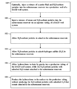
[0023] Fig. 1 is a flow chart of a first embodiment of a method of the
present invention, for
production of hydrocarbons from a subterranean reservoir using a steam
assisted gravity
drainage (SAGD) well system, and using H2S-sorbent particles to adsorb H2S in
the
subterranean reservoir.
[0024] Fig. 2 is a schematic depiction of a SAGD well system that may be used
in
implementing the method of Fig. 1, along with H2S-sorbent particles attached
to the
subterranean reservoir.
[0025] Figs. 3A to 3F are schematic depictions of sequential stages of the
method of Fig.
1.
[0026] Fig. 3A shows a subterranean reservoir in relation to an
injection tubing and
production tubing of a SAGD well system.
[0027] Fig. 3B shows injection of a carrier fluid mixed with H2S-sorbent
particles into the
subterranean reservoir via the production tubing.
[0028] Fig. 3C shows injection of steam mixed with H2S-sorbent particles
into the
subterranean reservoir via the injection tubing.
[0029] Fig. 3D shows H2S-sorbent particles attached to sand in the
subterranean reservoir,
and adsorbing H2S molecules in the subterranean reservoir.
[0030] Fig. 3E shows hydrocarbons draining by gravity into the production
tubing, while
the H2S-sorbent particles with adsorbed H2S remain attached to the
subterranean reservoir.
[0031] Fig. 3F shows production of hydrocarbons to the surface via the
production tubing
string.
6
WSLEGAL\ 065316\ 00166\31896861v1
Date Recue/Date Received 2022-07-28
DETAILED DESCRIPTION OF EMBODIMENTS OF THE INVENTION
[0032] Definitions.
[0033] The present invention relates to production of hydrocarbons from a
subterranean
reservoir using a steam injection operation, and H2S-sorbent particles to
adsorb hydrogen
sulfide (H2S) in the subterranean reservoir to reduce the amount of H2S, if
any, produced to
the surface.
[0034] Any term or expression not expressly defined herein shall have its
commonly
accepted definition understood by a person skilled in the art. As used herein,
the following
terms have the following meanings.
[0035] "Subterranean reservoir" refers to a subsurface body of rock having
porosity and
permeability that is sufficient to permit storage and transmission of a liquid
or gaseous fluid.
[0036] "Steam chamber", in the context of a SAGD well system, refers to
a region a
subterranean reservoir that is in fluid and pressure communication with an
injection well, and
that is subject to depletion of hydrocarbons, by gravity drainage, into a
production well that is
disposed parallel and below the injection well.
[0037] "Steam injection operation" refers to any method of producing
hydrocarbons from
a subterranean reservoir that involves injection of steam into the
subterranean reservoir to
decrease the viscosity of the hydrocarbons, so that the hydrocarbons flow more
easily in the
subterranean reservoir. Without limitation, steam injection operations include
methods known
in the art as steam assisted gravity drainage (SAGD), steam flooding or steam
drive, and cyclic
steam stimulation (C SS).
[0038] "Hydrocarbons" refer to hydrocarbon substances naturally
occurring in a
subterranean reservoir. Hydrocarbons may be in liquid, gaseous, or solid
phases. Without
limitation, hydrocarbons may include 'heavy oil", referring to hydrocarbons
having a mass
density of greater than about 900 kg/m3 under natural reservoir conditions.
Without limitation,
hydrocarbons may also include "bitumen" having a mass density of greater than
about 1,000
7
WSLEGAL\ 065316\ 00166\31896861v1
Date Recue/Date Received 2022-07-28
kg/m3 under natural reservoir conditions, and existing in semi-solid or solid
phase under natural
reservoir conditions. It will be understood that 'hydrocarbon production",
"producing
hydrocarbons" and like terms, as used herein, do not preclude co-production of
non-
hydrocarbon substances that may be mixed with hydrocarbons such as trace
metals, and gases
such as hydrogen sulfide that may be dissolved under natural reservoir
conditions, but exist in
a gaseous phase at surface conditions.
[0039] "H2S-sorbent particle" refers to a particle that has an affinity
for H2S. In
embodiments, this affinity may be based on principles of adsorption ¨ i.e.,
the H2S-sorbent
particle physically adheres and/or chemically bonds to H2S. In embodiments,
the H2S-sorbent
particle has a maximum dimension (e.g., a diameter) less than about 1000 nm,
more
particularly less than 500 nm, more particularly less than 250 nm. In
embodiments, the H2S-
sorbent particle is a "nanoparticle", which as used herein, refers to a
particle that has a
maximum dimension less than 100 nm. In embodiments, a nanoparticle may have a
maximum
dimension less than 50 nm, and more particularly less than 25 nm.
.. [0040] Metal-organic framework", and its abbreviation "MOF", refers to a
porous material
formed by compounds comprising metal ions or metal-ion clusters coordinated to
organic
ligands.
[0041] Method.
[0042] Fig. 1 is a flow chart of a first embodiment of a method of the
present invention, for
production of hydrocarbons from a subterranean reservoir using a steam
assisted gravity
drainage (SAGD) well system, and using H2S-sorbent particles to adsorb
hydrogen sulfide in
the subterranean reservoir.
[0043] Fig. 2 is a schematic depiction of a SAGD well system that may be used
in
implementing the method of Fig. 1. SAGD well systems and their principle of
operation are
.. well known to persons skilled in the art. The following description is
provided to facilitate
understanding of the present invention. For simplicity of illustration, Fig. 2
omits various
equipment items (e.g., steam generators, surface pumps, downhole pumps,
sealing elements
8
WSLEGAL\ 065316\ 00166\31896861v1
Date Recue/Date Received 2022-07-28
and so forth) that are commonly associated with a SAGD well system. The SAGD
well system
includes a horizontal or deviated (i.e. non-vertical) leg of an injection well
200 including an
injection tubing 202, and a horizontal or deviated (i.e. non-vertical) leg of
a production well
204 including a production tubing 206, extending from the surface 208 into a
subterranean
reservoir 210. The production well 204 is parallel to the injection well 200,
and disposed below
the injection well 200. A surface pump (not shown) is used to inject steam (as
shown by hollow
arrows) into the injection tubing 202, which exits via openings thereof, and
through openings
(e.g., a slotted liner) of the injection well 200 into a subterranean
reservoir so as to create a
steam-saturated zone referred to as the steam chamber 212. In the steam
chamber 212, the
injected steam heats the hydrocarbons and thereby reduces their viscosity. The
reduced-
viscosity hydrocarbons (as shown by solid arrows) drain downward by gravity
through
openings (e.g., a slotted liner) of the production well 204, and into the
production tubing 206.
The hydrocarbons are produced to the surface via the production tubing 206.
[0044] Fig. 3A is a schematic depiction of the injection tubing 202 and
production tubing
206 of a SAGD well system in a subterranean reservoir 210 before steam
injection. The
subterranean reservoir contains hydrocarbons, as shown by hydrocarbon
molecules 214, and
H2S, as shown by H2S molecules 216.
[0045] Referring back to Fig. 1, at step 100, a mixture of steam and H2S-
sorbent particles
are injected, via the injection tubing string 202, into the subterranean
reservoir. That is, H2S-
sorbent particles are injected in the steam phase of the SAGD operation. Fig.
3C is schematic
depiction of step 100, showing steam 218 mixed with H2S-sorbent particles 220
being pumped
into the subterranean reservoir 210. The H2S-sorbent particles 220 can be
suspended in the
injected steam 218 even at relatively low flow velocities of the injected
steam, on account of
the small size of the H2S-sorbent particles.
[0046] A variety of H2S-sorbent particles may be used in the present invention
to adsorb
H2S in the subterranean reservoir. Non-limiting examples are described below
under the
heading "H2S-sorbent particles." It will be evident that the H2S-sorbent
particles should have
high affinity for H2S-sorbent particles at pressure and temperatures
conditions in the
9
WSLEGAL\ 065316\ 00166\31896861v1
Date Recue/Date Received 2022-07-28
subterranean reservoir, and relatively little to no affinity for hydrocarbons
in the subterranean
reservoir under those conditions.
[0047] Preferably, the selected H2S-sorbent particles are capable of
adsorbing H2S over the
full range of temperatures expected to be encountered in the steam chamber of
a SAGD well
system, which typically ranges from about 15 C to about 300 C. In particular
embodiments,
the H2S-sorbent particles may have high affinity for H2S at temperatures of
about 110 C or
greater, more particularly of about 200 C or greater, and even more
particularly, of about 230
C or greater, to about 300 C. In this regard, calcium oxide (CaO) and iron
oxide (Fe2O3) are
reported to have been effective for H2S removal at high temperatures.
[0048] The H2S-sorbent particles should be sized so that they can permeate
through the
pores of the subterranean reservoir, without substantially impairing
transmission of a liquid or
gaseous fluid through the subterranean reservoir. A suitable size of H2S-
sorbent particles may
be selected having regard to the characteristics of a particular subterranean
reservoir. As a non-
limiting example, for subterranean reservoirs containing oil sands in Alberta,
Canada, a
suitable maximum dimension (e.g., diameter) of H2S-sorbent particles may be
less than about
1,000 nm, more particularly less than about 500 nm, and even more particularly
less than about
250 nm. In some embodiments, the H2S-sorbent particles may be nanoparticles ¨
i.e., particles
having a maximum dimension (e.g., diameter) less than about 100 nm, more
particularly less
than about 50 nm, and even more particularly less than about 25 nm.
[0049] Use of H2S-sorbent particles having higher surface area per mass may
increase their
efficacy in adsorption of the H2S gas. In embodiments, the H2S-sorbent
particles have a surface
area per mass in the range from about 1 to about 3,000 m2/g. In some
embodiments, the surface
area per mass may be greater than 50 m2/g, greater than about 100 m2/g,
greater than about 250
m2/g, greater than about 500 m2/g, greater than about 750 m2/g, and greater
than about 1,000
m2/g.
[0050] The H2S-sorbent particles may be selected to have a desired
adsorption capacity,
having regard to factors such as the amount or concentration of the H2S gas to
be sequestered,
or a desired rate of sequestration. For example, they may have an adsorption
capacity (mg H2S
WSLEGAL\ 065316\ 00166 \ 31896861v1
Date Recue/Date Received 2022-07-28
/ g sorbent material) in the range from about 0.1 ¨ 15,000 mg/g. In some
embodiments, the
adsorption capacity may be greater than about 10 mg/g, more particularly
greater than about
50 mg/g, more particularly greater than about 100 mg/g, more particularly
greater than about
500 mg/g, and more particularly greater than about 1,000 mg/g.
[0051] Having regard to the H2S affinity of the selected H2S-sorbent
particles, the
concentration of H2S-sorbent particles in the mixture may be selected to be
effective in
absorbing H2S present in concentrations in the hydrocarbons in the
subterranean reservoir,
which typically range from about 100 ppm to about 30,000 ppm.
[0052] In Fig. 1, at step 102, the H2S-sorbent particles that were
injected into the
subterranean reservoir in step 100, are allowed to attach to the subterranean
reservoir. This
step may be performed without any active intervention, by allowing for
relatively quiescent
conditions in the subterranean reservoir. For example, injection of the steam
is ceased to leave
the H2S-sorbent particles in the subterranean reservoir relatively
undisturbed. The H2S-sorbent
particles will adhere to sand particles in the subterranean reservoir, owing
to the small size of
the H2S-sorbent particles. Fig. 3D is schematic depiction of step 102, showing
the H2S-sorbent
particles 220 attached to sand particles of the subterranean reservoir 200
after cessation of
steam injection.
[0053] In Fig. 1, at step 104, the H2S-sorbent particles are allowed to
adsorb hydrogen
sulfide (H2S) in the subterranean reservoir. Fig. 3D is a schematic depiction
of this step
showing the H2S-sorbent particles 220 attached to sand particles of the
subterranean reservoir
200 and the adsorbed H2S molecules 216.
[0054] In Fig. 1, at step 106, the hydrocarbons are allowed to drain by
gravity into the
production tubing string, while the H2S-sorbent particles with adsorbed H2S
remain attached
to the subterranean reservoir. Fig. 3E is a schematic depiction of this step
showing hydrocarbon
molecules 214 within the production tubing 206 while the H2S-sorbent particles
220 and
adsorbed H2S molecules 216 remain in the region of the steam chamber.
11
WSLEGAL\ 065316\ 00166\31896861v1
Date Recue/Date Received 2022-07-28
[0055] In Fig. 1, at step 108, the hydrocarbons are produced to the
surface via the
production tubing. Fig. 3F is a schematic depiction of this step showing the
hydrocarbon
molecules 214 flowing to the surface via the production tubing 206.
[0056] As known to persons skilled in the art, SAGD (and other steam injection
operations
as described below) may be performed over many years with multiple cycles of a
steam
injection phase followed by a hydrocarbon production phase. Accordingly, steps
100 to 108
may be performed repeatedly in cycles, with each performance of step 100
corresponding to a
steam injection phase of a cycle, and each performance of step 108
corresponding to a
hydrocarbon production phase of the cycle. In particular, the amount or
concentration of H2S-
sorbent particles in the mixture that is injected into the subterranean
reservoir at each cycle
may be selectively varied, possibly to account for factors such as the amount
or concentration
of H2S-sorbent particles that have been previously injected in past cycles, or
will be injected
in subsequent cycles. This can be used to achieve a variety of advantageous
effects. As one
example, the concentration or amount of H2S-sorbent particles that is injected
in any given
cycle can be limited, with a view to incrementally increasing the
concentration or amount of
H2S-sorbent particles attached to the subterranean reservoir over multiple
cycles. As another
example, the concentration or amount of H2S-sorbent particles that is injected
in any given
cycle can be selected to control the distribution of H2S-sorbent particles in
the subterranean
reservoir. For instance, the volumetric portion of the subterranean reservoir
that is "seeded"
with the H2S-sorbent particles can be incrementally increased over multiple
cycles. As still
another example, the concentration or amount of H2S-sorbent particles in the
mixture that is
injected in any given cycle can be varied over cycles to account for varying
levels of H2S
concentration in produced fluids during the operation of the well, or to
selectively vary the H2S
concentration of fluids produced to the surface during the operation of the
well.
[0057] Referring back to Fig. 1, the method may also include an optional
step 110 that is
applicable to steam injection operations, such as SAGD or steam flooding that
use two wells,
where one of the wells is an injection well for injection of steam, and the
other well is a
production well for production of hydrocarbons to the surface. At step 110, a
mixture of a
carrier fluid and additional H2S-sorbent particles are injected via the
production tubing string
12
WSLEGAL\ 065316\ 00166\31896861v1
Date Recue/Date Received 2022-07-28
206 of the production well 204 into the subterranean reservoir. That is, the
production tubing
string 206 is used in a non-conventional manner to convey material from the
surface into the
subterranean reservoir. Fig. 3B is a schematic depiction of step 110, showing
the carrier fluid
222 mixed with additional H2S-sorbent particles 220 being pumped into the
subterranean
reservoir. In embodiments, the carrier fluid 222 may be a liquid such as
water. In embodiments,
the carrier fluid 222 may be a gas, such as a nitrogen. The carrier fluid may
be transported to
the well head of the production well such as by truck or other means. In like
manner as the
H2S-sorbent particles that are injected at step 100, the additional H2S-
sorbent particles that are
injected in step 110 will attach the subterranean reservoir (but more so in
the vicinity of the
production well), adsorb H2S in the subterranean reservoir including from the
hydrocarbons
that have drained by gravity from the steam chamber, and sequester the H2S
particles in the
subterranean reservoir as the hydrocarbons are produced to the surface. Fig.
1, and the
sequence of Figs. 3A to 3F, show step 110 as being performed prior to steps
100 to 108.
However, it will be understood that step 110 may be performed periodically,
and in other orders
relative to these steps, but preferably in such an order that does not
interfere with migration of
hydrocarbons to the production well, and production of hydrocarbons to the
surface via the
production well. Further, by use of flow control devices associated with the
production well,
the carrier fluid and additional H2S-sorbent particles may be injected into
those portions of the
subterranean reservoir surrounding production well where non-condensable gases
(including
H2S) are most likely to be produced. Such locations may be predicted by
persons skilled in the
art, and/or determined empirically when the well system is in operation.
[0058] Controlled placement of H2S-s orbe nt particles.
[0059] The contact time between non-condensable gases and the H25-sorbent
particles in
the subterranean reservoir may be quite brief due to flow of the gas phase. As
such, creating
regions of the subterranean reservoir that have higher concentrations of H25-
sorbent particles,
and preferentially promoting flow of non-condensable gases (including H25)
through such
regions may promote contact of H25 with the H25-sorbent particles, and
therefore make the
most economical and effective use of the H25-sorbent particles.
13
WSLEGAL\ 065316\ 00166\31896861v1
Date Recue/Date Received 2022-07-28
[0060] As a non-limiting example, referring back to the Fig. 2, the
injection tubing 202 may
include a plurality of steam flow control devices, including a first steam
flow control device
224 and a second steam flow control device 226, disposed at different
positions along the
subterranean reservoir. "Steam flow control device", as used herein, refers to
any mechanical
device that can be incorporated into a downhole string, and actuated to
selectively control flow
of steam out of the downhole tubing and into the surrounding wellbore. (Steam
flow control
devices are known to persons skilled in the art, and by themselves do not
constitute part of the
present invention. Steam flow control devices may be referred to in the art as
"steam splitters",
"steam diverter", "steam valves", "steam injection mandrels", and like terms.
As a non-limiting
example, a steam flow control device may comprise a body defining a bore, and
a sleeve or
other valve member that is movable relative to the body between alternate
positions that either
block or allow steam to flow out of openings defined by the bore. Movement of
the sleeve or
valve member may be actuated by means such as shift tools, balls, or other
mechanisms as
known to persons skilled in the art.)
[0061] By control of the steam flow control devices (and the use of
possible sealing
elements associated with the injection tubing 202, such as sealing elements
used for zonal
isolation), it is possible to establish pressure gradients of the steam mixed
with 1125-sorbent
particles 220 that are injected into the subterranean reservoir in step 100.
These pressure
gradients will affect the distribution of 1125-sorbent particles 220, as the
injected steam and
1125-sorbent particles 220 will tend to migrate from regions of higher
pressure to regions of
lower pressure. In Fig. 2, for example, closing of the first steam flow
control device 224 and
opening of the second steam flow control device 226 may create a region of
relatively lower
pressure in the vicinity of the first steam flow control device 224, and a
region of relatively
higher pressure in the vicinity of the second steam flow control device 226.
Accordingly, 1125-
sorbent particles 220 injected into the subterranean formation via the second
steam flow control
device 226 may tend to flow from right to left in the drawing plane of Fig. 2.
This may result
in a region having a higher concentration of 1125-sorbent particles 220 in the
vicinity of the
second steam flow control device 226, as compared with the region in the
vicinity of the first
steam flow control device 224. (The 1125-sorbent particles 220 would be
expected to become
14
WSLEGAL\ 065316\ 00166\31896861v1
Date Recue/Date Received 2022-07-28
more diffuse in concentration with increased distance from their injection
location at the
second steam flow control device 226.)
[0062] Pressure gradients also tend to cause non-condensable gases in the
steam chamber
212 to flow from regions of relatively high pressure to regions of relatively
low pressure.
Accordingly, the steam flow control devices or other means may also be
selectively controlled
to establish a pressure gradient that affects the flow of non-condensable
gases in the steam
chamber 212 to regions of the steam chamber 212 having relatively higher
concentrations of
H2S-sorbent particles 220. For example, after the H2S-sorbent particles 220
are allowed to
attach the sand particles of the subterranean reservoir, injection of steam
(without further
injection H2S-sorbent particles 220) into the steam chamber 212 may be
continued. Opening
of the first steam flow control device 224 and closing of the second steam
flow control device
226 may create a region of relatively higher pressure in the vicinity of the
first steam flow
control device 224, as compared with the region in the vicinity of the second
steam flow control
device 226. Accordingly, non-condensable gases (possibly including hydrogen
sulfide) will
tend to flow from left to right in the drawing plane of Fig. 2, so as to flow
through the region
of the steam chamber 212 in the vicinity of the second steam flow control
device 226 having
the relatively higher concentration of H2S-sorbent particles 220,
preferentially over other
regions having relatively lower concentrations of H2S-sorbent particles 220.
[0063] Adaption to other well systems and steam injection operations.
[0064] In the embodiment of Figs. 3A to 3F, the method is implemented using a
SAGD
well system. In other embodiments, the method may be implemented for other
steam injection
operations, including cyclic steam stimulation (CSS), steam flooding or steam
drive.
[0065] As known in the art, cyclic steam stimulation typically involves
a "steam phase" of
injecting steam into the reservoir via the well, a "soak phase" of allowing
the steam to soak
into the reservoir in the vicinity of the well and thereby reduce viscosity of
hydrocarbons, and
a "production phase" of producing hydrocarbons to the surface from the same
well. The method
of the present invention may be implemented by: injecting a mixture of steam
and H2S-sorbent
particles into the subterranean reservoir via the well during the "steam
phase"; allowing H2S-
WSLEGAL\ 065316\ 00166\31896861v1
Date Recue/Date Received 2022-07-28
sorbent particles to attach to the subterranean reservoir, and adsorb hydrogen
sulfide (H2S) in
the subterranean reservoir during the "soak phase"; and producing the
hydrocarbons to the
surface via the same well during the "production phase", without producing the
H2S-sorbent
particles with adsorbed H2S that remain attached to the subterranean
reservoir, Thus, it will be
understood that the method may be implemented using a single well system,
which may be a
vertical well.
[0066] As known in the art, steam flooding or steam drive typically
involves injecting steam
into a reservoir via a first well to reduce the viscosity of hydrocarbons and
displace the
hydrocarbons toward a different second well. In contrast to SAGD, the first
well and the second
well may both be entirely vertical wells that are horizontally spaced apart
from each other. The
method of the present invention may be implemented by: injecting a mixture of
steam and H2S-
sorbent particles into the subterranean reservoir via the first well; allowing
H2S-sorbent
particles to attach to the subterranean reservoir that is disposed
horizontally between the first
and second wells, and adsorb hydrogen sulfide (H2S) in that subterranean
reservoir; and
producing the hydrocarbons to the surface via the second well, without
producing the H2S-
sorbent particles with adsorbed H2S that remain attached to the subterranean
reservoir. Thus,
it will be understood that the method may be implemented using a dual well
system having a
pair of entirely vertical wells.
[0067] H2S-s orbent particles.
[0068] The following description provides non-limiting examples of
particles that are
believed would be useful in the present invention to adsorb H2S in the
subterranean reservoir,
and a line of reasoning for their use. In general, References no. 1 to 14,
below, provide
information regarding efficacy of nanoparticles for adsorption of H2S. It is
believed that such
nanoparticles would be effective in adsorption of at least some amount of H2S
in temperature
and pressure conditions typically encountered in a subterranean reservoir.
16
WSLEGAL\ 065316\ 00166\31896861v1
Date Recue/Date Received 2022-07-28
[0069] Zinc oxide (ZnO) particles.
[0070] Zinc oxide and H2S react to produce zinc sulfide (ZnS) and water,
according to the
following reaction.
ZnO(s) + H2S(g) 4 ZnS (s) + H20(l)
[0071] Zinc oxide particles are typically a solid, white, and odorless powder.
Zinc oxide may
be more stable and cost effective when compared with other adsorbents. A
possible
disadvantage is the limited feasibility of regeneration ¨ i.e., desorption of
adsorbed H2S to
render the particle able to adsorb H2S again.
[0072] Reference no. 1 [Awume] reports performance characteristics of zinc
oxide
nanoparticles in the removal of H2S from gas streams. At ambient temperatures
zinc oxide
nanoparticles are up to 99% effective in capturing H2S gas. As feed H2S
concentrations
increases, the adsorption capacity also increases and the nanoparticles reach
a saturation state
more quickly, as summarized below in Table 1. Smaller zinc oxide nanoparticles
(18 nm) have
an overall higher adsorption capacity compared to larger particles (80 nm ¨
200 nm). Larger
zinc oxide nanoparticles, however, reached their saturation state faster,
regardless of H25 feed
concentration.
Table 1
H25 Feed Concentration Equilibrium H25 Adsorbed
(mg/L) (g/g adsorbent)
94.70 9.2
233.43 9.8
540.60 10.6
814.76 10.6
964.2 11.4
1501.85 14.9
[0073] The saturation rate of adsorbent is unaffected by temperature,
but the adsorption
capacity of zinc oxide nanoparticles increases with an increase in
temperature, as summarized
below in Table 2.
17
WSLEGAL\ 065316\ 00166\31896861v1
Date Recue/Date Received 2022-07-28
Table 2
Temperature 541.4 mg/L 1567.8 mg/L
( C) Equilibrium H2S Equilibrium H2S
Adsorbed (g/g adsorbent) Adsorbed (g/g adsorbent)
1 8.35 -
11 9.21 12
22 10.58 14.9
41 11.17 16.6
[0074] Adsorption capacities increase with an increase in the zinc oxide
nanoparticle
quantity. The saturation rate of the adsorbent was higher with a decrease in
nanopartic le
quantity, regardless of the H2S feed concentration.
[0075] Synthesized zinc oxide nanoparticles (14 ¨25 nm) c an c ompletely
remove H2S from
water-based drilling mud in ¨15 minutes, whereas bulk zinc oxide can remove
¨2.5% of H2S
in as long as 90 minutes under the same operating conditions.
[0076] Reference no. 6 [Whittaker] describes NanoActive TM Sulphur Scavenger
(NASS)
(Timilon Technology Acquisitions LLC; Naples, FL, USA), which is a zinc oxide
(ZnO)
nanoparticle sulphur recovery technology developed for the neutralization of
H25 in crude oil
and gas streams. Whittaker reports that NASS's two-step decomposition
mechanism
(adsorption by physisorption, followed by nonreversible chemical
decomposition)
substantially enhances its detoxification abilities because decomposition is
less dependent on
temperature. Whittaker reports that use of NASSTM improves scavenger efficacy
between 4
and 6 times, depending on feed composition. Whittaker reports that the range
at which NASS
stand-alone systems are economical is up to 10,000 ppm H25 in liquid streams,
and 1,000 ppm
H25 at 320 m3/hr to 10,000 ppm H25 at 30 m3/hr in gas streams. At these
levels, NASS reduces
H25 to 0 ppm. For higher concentrations, NASS is used in combination with
existing removal
technologies.
18
WSLEGAL\065316\00166\31896861v1
Date Recue/Date Received 2022-07-28
[0077] Iron oxide (Fe2O3) particles.
[0078] Iron oxide reacts with H2S to produce iron sulfide (Fe S) and
water, according to the
following reaction.
Fe2O3 + 3H2S 4 Fe2S3 + 3H20
.. [0079] Iron oxide nanoparticles have been shown to be very effective for
H2S removal from
gas streams at temperatures in excess in 300 C. Reference no. 12 [Blatt et
al.] indicates that
impregnating a custom-activated carbon with these nanoparticles resulted in a
slight enhanced
removal efficiency.
[0080] SULFATREATTm (Schlumberger Limited, Houston, TX, USA) is a granular
iron
.. oxide based 1125 adsorbent and SELECT FAMILY TM (Schlumberger Limited,
Houston, TX,
USA) is a mixed metal oxide-based H25 adsorbent, both of which are used to
remove H25 from
gas streams in fixed bed processes. It is possible that these sorbents may be
physically reduced
to nanoparticle size.
[0081] Magnetite (Fe 3 04) particles.
[0082] Magnetite reacts with H25 at low pH to form hydrogen as a byproduct,
according to
the following equation.
Fe304+ 6H25 4 3FeS2 + 41-120 + 2H2
[0083] Reference no. 4 [Martinez et al.] reports that magnetite
nanoparticles have reached
more than 93% in HS mitigation.
.. [0084] Copper oxide (CuO) particles.
[0085] Copper oxide reacts with H25 is according to the following
equation.
CuO + H2S 4 CuS +H20
19
WSLEGAL\ 065316\ 00166\31896861v1
Date Recue/Date Received 2022-07-28
[0086] Reference no. 4 [Martinez et al.] reports that copper oxide is
thermodynamic ally
favorable for sulphur removal, and that the reaction between copper oxides and
sulfides is very
fast and effective. Also, this oxide can be reduced to the metallic copper
easily.
[0087] Reference no. 7 [Georgiadis et al.] reports that the presence of
copper increased the
.. mobility of sulfur anions in Cu¨containing ZnS particles. Georgiadis et al.
also reports that
CuO has an extremely high equilibrium sulfidation constant that allows an
extremely low
equilibrium constant even at high temperatures.
[0088] Adsorbents with high Cu concentrations have been shown to be more
efficient in
capturing H2S compared to adsorbents with high Zn concentrations.
[0089] Nickel oxide (NiO) particles.
[0090] Nickel oxide reacts with H2S is according to the following
equation.
NiO + H2S 4 NiS + H20
[0091] Reference no. 4 [Martinez et al.] reports results in H2S
mitigation (83%) in studies
of the application of nickel nanoparticles to treat heavy crude oil, Martinez
et al. reports that
three faces of nickel were generated (NiO, Ni and Ni2S3), and for this
reason, it was difficult
to determine which material is working as the scavenger.
[0092] Gold (Au) particles.
[0093] Reference no. 8 [Mubeen et al.] reports that H2S is known to adsorb
strongly onto
gold because of the high chemical affinity between gold and sulphur. At
temperatures between
165 K and 520 K, H2S decomposes to form SH which is chemisorbed onto the
gold surface
while H2 is released. However, gold nanoparticles are a very expensive option
and there is not
much literature relating to gold and H2S adsorption.
[0094] Calcium oxide (CaO) particles.
[0095] Calcium oxide reacts with H2S is according to the following
equation.
WSLEGAL\065316\00166\31896861v1
Date Recue/Date Received 2022-07-28
CaO + H2S 4 CaS + H20
[0096] Reference no. 10 [Wang] reports that calcium oxide a good choice for
H2S
adsorption at elevated temperatures (250 ¨ 500 C).
[0097] Manganese oxide (1VIn02) particles.
[0098] Manganese oxide reacts non-catalytically with H2S is according to
the following
equation.
Mn02 + 2H2S 4 MnS + S + 2H20
[0099] Reference no. 9 [Konkol et al.] reports that desulphurization
performance of
different metallic oxides on activated carbon decreases in the following
order: Mn > Cu > Fe
> Ce > Co > V.
[00100] Molybdenum oxide (M o 02) particles.
[00101] Reference no. 13 [Has sankiadeh et al.] reports that molybdenum oxide
nanopartic le s
have an adsorption capacity of 0.081 and 0.074 g H2S/g molybdenum oxide in low
temperature
and low concentration of H2S using non-spherical and spherical molybdenum
oxide sorbent,
respectively.
[00102] Metal-organic frameworks.
[00103] Non-limiting examples of MOFs that maybe used to adsorb H2S are
reviewed by
Georgiadis et al. [Reference no. 7], and Georgiadis et al. [Reference no. 22],
including MOFs
based on vanadium, aluminum, chromium, titanium, zeolites, zinc, zinc oxide,
zirconium
oxide, graphite oxide, and MOF's known as M-MOF-74, and Ni-MOF-74.
[00104] Interpretation.
[00105] The corresponding structures, materials, acts, and equivalents of all
means or steps
plus function elements in the claims appended to this specification are
intended to include any
21
WSLEGAL\ 065316\ 00166\31896861v1
Date Recue/Date Received 2022-07-28
structure, material, or act for performing the function in combination with
other claimed
elements as specifically claimed.
[00106] References in the specification to "one embodiment", "an embodiment",
etc.,
indicate that the embodiment described may include a particular aspect,
feature, structure, or
characteristic, but not every embodiment necessarily includes that aspect,
feature, structure, or
characteristic. Moreover, such phrases may, but do not necessarily, refer to
the same
embodiment referred to in other portions of the specification. Further, when a
particular aspect,
feature, structure, or characteristic is described in connection with an
embodiment, it is within
the knowledge of one skilled in the art to affect or connect such module,
aspect, feature,
structure, or characteristic with other embodiments, whether or not explicitly
described. In
other words, any module, element or feature may be combined with any other
element or
feature in different embodiments, unless there is an obvious or inherent
incompatibility, or it
is specifically excluded.
[00107] It is further noted that the claims may be drafted to exclude any
optional element.
As such, this statement is intended to serve as antecedent basis for the use
of exclusive
terminology, such as "solely," "only," and the like, in connection with the
recitation of claim
elements or use of a "negative" limitation. The terms "preferably,"
"preferred," "prefer,"
"optionally," "may," and similar terms are used to indicate that an item,
condition or step being
referred to is an optional (not required) feature of the invention.
[00108] The singular forms "a," "an," and "the" include the plural reference
unless the
context clearly dictates otherwise. The term "and/or" means any one of the
items, any
combination of the items, or all of the items with which this term is
associated. The phrase
"one or more" is readily understood by one of skill in the art, particularly
when read in context
of its usage.
[00109] The term "about" can refer to a variation of 5%, 10%, 20%, or
25% of the
value specified. For example, "about 50" percent can in some embodiments carry
a variation
from 45 to 55 percent. For integer ranges, the term "about" can include one or
two integers
greater than and/or less than a recited integer at each end of the range.
Unless indicated
22
WSLEGAL\ 065316\ 00166\31896861v1
Date Recue/Date Received 2022-07-28
otherwise herein, the term "about" is intended to include values and ranges
proximate to the
recited range that are equivalent in terms of the functionality of the
composition, or the
embodiment.
[00110] As will be understood by one skilled in the art, for any and all
purposes, particularly
in terms of providing a written description, all ranges recited herein also
encompass any and
all possible sub-ranges and combinations of sub-ranges thereof, as well as the
individual values
making up the range, particularly integer values. A recited range includes
each specific value,
integer, decimal, or identity within the range. Any listed range can be easily
recognized as
sufficiently describing and enabling the same range being broken down into at
least equal
halves, thirds, quarters, fifths, or tenths. As a non-limiting example, each
range discussed
herein can be readily broken down into a lower third, middle third and upper
third, etc.
[00111] As will also be understood by one skilled in the art, all language
such as "up to", "at
least", "greater than", "less than", "more than", "or more", and the like,
include the number
recited and such terms refer to ranges that can be subsequently broken down
into sub-ranges
as discussed above. In the same manner, all ratios recited herein also include
all sub-ratios
falling within the broader ratio.
REFERENCES
[00112] All publications, patents and patent applications mentioned in this
specification are
indicative of the level of skill of those skilled in the art to which this
invention pertains and are
herein incorporated by reference, where permitted, to the same extent as if
each individual
publication, patent, or patent applications was specifically and individually
indicated to be
incorporated by reference.
Non-Patent Literature
1. Awume, Bennet. Control of Hydrogen Sulphide Emissions Using Zinc
Oxide
Nanoparticles. Thesis, University of Saskatchewan. July 2014.
23
WSLEGAL\ 065316\ 00166\31896861v1
Date Recue/Date Received 2022-07-28
2. Sekhavatjou, M., Moradi, R., Hosseini Alhashemi, A., & Taghinia Hejabi,
A. A New
Method For Sulphur Components Removal From Sour Gas Through Application of
Zinc And Iron Oxides Nanoparticles. International Journal of Environmental
Research (IJER) 8(2), 273-278. 2014.
3. Abdelrahman Ibrahim El-Diasty, SPE, The American University in Cairo
(AUC) and
Suez University, Egypt and Adel M. Salem Ragab. Applications of Nanotechnology
in the Oil & Gas Industry: Latest Trends Worldwide & Future Challenges in
Egypt.
Society of Petroleum Engineers. 2013.
4. S. I. Martinez, PDVSA Intevep S.A.; C. Bastidas, Universidad Nacional
Experimental Politecnica de la Fuerza Armada. Application of Transition Metal
Nanoparticles in the Streams Production of Heavy Crude Oil Treatment: H25
Mitigation. Society of Petroleum Engineers. 2017.
5. Christof Weinlaender, Raphael Neubauer, Christoph Hochenauer. Low-
temperature
H25 removal for solid oxide fuel cell application with metal oxide adsorbents.
October 7, 2016.
6. S. L. Whittaker, Clean Stream Technologies Middle East FZE. Use of
NanoActive0
Sulphur Scavenger NASS for H25 Removal in the Oil and Gas Industry. Society of
Petroleum Engineers. 2018.
7. Amvrosios G. Georgiadis, Nikolaos D. Charisiou and Maria A. Goula.
Removal of
Hydrogen Sulfide From Various Industrial Gases: A Review of The Most Promising
Adsorbing Materials. May 8, 2020.
8. Syed Mubeen, Ting Zhang, Nicha Chartuprayoon, Youngwoo Rheem, Ashok
Mulchandani, Nosang V. Myung, and Marc A. Deshusses. Sensitive Detection of
H25
Using Gold Nanoparticles Decorated SWNTs. Anal. Chem. 2010; 82(1); 250-257.
24
WSLEGAL\ 065316\ 00166\31896861v1
Date Recue/Date Received 2022-07-28
9. Izabela Konkol, Jan Cebula, Adam Cenian. Oxidization of hydrogen
sulphide in
biogas by manganese (IV) oxide particles. Environmental Engineering Research.
2021; 26(2): 190343 (eeer.org).
10. Wang, De Ming. "Breakthrough behavior of H2S removal with an iron oxide
based
CG-4 adsorbent in a fixed-bed reactor." Thesis, University of Saskatchewan.
September 2008.
11. Costa, C.; Cornacchia, M.; Pagliero, M.; Fabiano, B.; Vocciante, M.;
Reverberi, A.P.
Hydrogen Sulfide Adsorption by Iron Oxides and Their Polymer Composites: A
Case-Study Application to Biogas Purification. Materials 2020, 13, 4725.
12. Blatt, O., Helmich, M., Steuten, B., Hardt, S., Bathen, D. and Wiggers,
H. (2014),
Iron Oxide/Polymer-Based Nanocomposite Material for Hydrogen Sulfide
Adsorption Applications. Chem. Eng. Technol., 37: 1938-1944.
13. Nabipoor Hassankiadeh, Mojtaba & Hallajisani, Ahmad. (2020). Abstract
of
Application of Molybdenum oxide nanoparticles in HS removal from natural gas
under different operational and geometrical conditions. Journal of Petroleum
Science
and Engineering. 190.
14. Alberta Energy and Utilities Board, Interim Directive ID 2001-3.
Sulphur Recovery
Guidelines for the Province of Alberta. August 29, 2001.
15. Ravinder Kumar, Rajesh Mangalapuri, Mohammad Hossein Ahmadi, Dai-Viet N
Vo,
Rajniesh Solanki, Pawan Kumar, The role of nanotechnology on post-combustion
CO2 absorption in process industries, International Journal of Low-Carbon
Technologies, Volume 15, Issue 3, August 2020, Pages 361-367.
16. Kim, Jinguk & Fu, Qiang & Xie, K. & Scofield, Joel & Kentish, Sandra &
Qiao,
Greg. (2016). CO2 Separation using Surface-functionalized 5i02 Nanoparticles
incorporated Ultra-Thin Film Composite Mixed Matrix Membranes for Post-
combustion Carbon Capture. Journal of Membrane Science. 515.
WSLEGAL\ 065316\ 00166\31896861v1
Date Recue/Date Received 2022-07-28
17. Lin KY, Park AH. Effects of bonding types and functional groups on CO2
capture
using novel multiphase systems of liquid-like nanoparticle organic hybrid
materials.
Environ Sci Technol. 2011 Aug 1; 45(15):6633-9.
18. Ota, M.; Hirota, Y.; Uchida, Y.; Nishiyama, N. CO2 Adsorption Property
of Amine-
Modified Amorphous TiO2 Nanoparticles with a High Surface Area. Colloids
Interfaces 2018, 2,25.
19. Zhang, Huiying & Liu, Ruiqiang & Ning, Tangyuan & Lal, Rattan. (2018).
Higher
CO2 absorption using a new class of calcium hydroxide (Ca(OH)2) nanoparticles.
Environmental Chemistry Letters.
20. Isahak, Wan & Che Ramli, Zatil Amali & Lahuri, Azizul & Yusop, Rahimi &
Wahab, Mohamed & Yarmo, Ambar. (2015). Enhancement of CO2 Capture Using
CuO Nanoparticles Supported on Green Activated Carbon. Advanced Materials
Research. 1087. 111-115.
21. Mishra, Ashish & Sundara, Ramaprabhu. (2011). Nano magnetite decorated
multiwalled carbon nanotubes: A robust nanomaterial for enhanced Carbon
Dioxide
adsorption. Energy Environ. Sci.. 4. 889-895.
22. Georgiadis, A.G.; Charisiou, N.D.; Yentekakis, I.V.; Goula, M.A.
Removal of
Hydrogen Sulfide (H25) Using MOFs: A Review of the Latest Developments. Chem.
Proc. 2020, 2, 27.
Patent documents
23. Canadian patent application publication no. 2,897,078 Al (Sun et al.;
January 1,
2016), titled "Systems and Methods for Removal of Sulfur from Flue Gas".
24. Canadian patent application publication no. 2,915,623 Al (Gupta et al;
December 18,
2015), titled "Separation of Carbon Dioxide from Flue Gases".
26
WSLEGAL\ 065316\ 00166\31896861v1
Date Recue/Date Received 2022-07-28
25.
Canadian patent application publication no. 2,916,141 Al (Chhina et al;
December
22, 2015), titled "Methods, Systems and Apparatuses for Capturing and
Sequestering
Carbon Dioxide Emitted from a Vehicle".
27
WSLEGAL\ 065316\ 00166\31896861v1
Date Recue/Date Received 2022-07-28