Note: Descriptions are shown in the official language in which they were submitted.
CA 03169646 2022-07-28
WO 2021/159085
PCT/US2021/017103
LAMINATE CONTAINER
PRIORITY CLAIM
This application claims priority under 35 U.S.C. 119(e) to U.S. Provisional
Application Serial No. 62/971,553, filed February 7, 2020, which is expressly
incorporated by reference herein.
TECHNICAL FIELD
The present disclosure relates generally to a container, and more specifically
to a
laminate container formed from a sheet laminated with a base layer.
BACKGROUND
It is often desirable to store product or contents in a container or package.
It is
often desirable to provide the container or package with multiple layers for a
purpose or
variety of purposes, such as a barrier layer that may increase the shelf life
of the container
or package contents, a layer for decorative purposes, for tactile purposes, or
for any other
purpose or combination of purposes. A container or package may be provided
with
multiple layers for any or all of these purposes while being provided in a way
that
optimizes or minimizes the amount of material required to achieve them. For
example, the
laminate container discussed herein may be used for as a part of a package for
use in a
beverage brewing system, such as a single use beverage brewing system. A
package may
be provided that may be used in such a system, wherein the package has barrier
properties
that may enhance the shelf life of its contents while also minimizing or
optimizing the
materials used therein, and/or facilitating recyclability of the container or
package.
SUMMARY
Certain embodiments according to the present disclosure provide a container
formed from a laminate including a base layer and a sheet. The sheet may be
relatively
thin and provide any of a variety of properties, such as barrier properties,
sealing
properties, or decoration, for example.
In one aspect, for instance, a container may be provided having a side wall
having
a side wall area and a bottom having a bottom area. The side wall and bottom
are formed
from a laminate having a base layer and a sheet. The base layer has a base
layer thickness
1
CA 03169646 2022-07-28
WO 2021/159085
PCT/US2021/017103
and the sheet has a sheet thickness. The laminate has a laminate thickness
that is at least
the sum of the base layer thickness and the sheet thickness. The sheet has at
least one
sheet layer and the at least one sheet layer has a thickness that is equal to
or less than 5%
of the laminate thickness. The side wall and bottom at least partially define
a part area.
The container is formed from the laminate having a laminate area used to form
the
container. The formed container has an areal draw ratio of greater than about
2.5.
In another aspect, for instance, a container may be provided having a side
wall
having a side wall area and a bottom having a bottom area. The side wall and
bottom are
formed from a laminate having a base layer and a sheet. The sheet has a sheet
thickness,
the sheet includes at least one barrier layer having a barrier layer
thickness, and wherein
the base layer has a base layer thickness. The laminate has a laminate
thickness. The
barrier layer thickness is less than about 5% of the laminate thickness. The
side wall and
bottom at least partially define a part area. The container is formed from a
portion of
laminate having a laminate area. The container has an areal draw ratio of
greater than
about 2.5.
In yet another aspect, for instance, a process for forming a container is
provided.
A base layer is formed from a base layer material. A sheet having at least one
layer is
provided. The base layer is laminated to the sheet to form a laminate. The
laminate is
thermoformed into a part with an areal draw ratio of at least about 2.5.
BRIEF DESCRIPTION OF THE DRAWINGS
Embodiments now will be described more fully hereinafter with reference to the
accompanying drawings, in which some, but not all embodiments may be shown.
Indeed,
embodiments may be illustrated or described in many different forms and the
present
disclosure should not be construed as limited to the embodiments set forth
herein. Like
numbers refer to like elements throughout, and wherein:
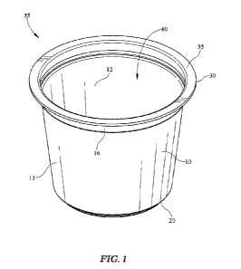
FIG. 1 illustrates a perspective view of an embodiment of a generally
cylindrical
container, which may be configured for use in a beverage brewing system, for
example;
FIG. 2 illustrates a perspective view of an embodiment of a pod type package
incorporating the container of FIG. 1, which may be used for example in a
beverage
brewing system;
2
CA 03169646 2022-07-28
WO 2021/159085
PCT/US2021/017103
FIG. 3 illustrates a perspective view of another embodiment of a container,
which
is generally rectangular;
FIG. 4 illustrates a perspective view of another embodiment of a package
incorporating the container of FIG. 3;
FIG. 5 illustrates a side perspective view of a portion of an embodiment of a
laminate that may be used to form a container;
FIG. 6 illustrates a cross-section side view of the portion of laminate of
FIG. 4;
FIG. 7 illustrates a cross-section side view of another embodiment of a
laminate,
which has a base layer and a three layer sheet or film;
FIG. 8 illustrates a side view of a portion of yet another embodiment of a
laminate;
FIG. 9 illustrates an embodiment of a laminate forming apparatus and process;
FIG. 10 illustrates an embodiment of a thermoforming apparatus and process;
FIG. 11 illustrates a top view of a portion of an embodiment of a sheet in
disk form
suitable for use in a forming process;
FIG. 12 illustrates a side perspective view of the disk of FIG. 9;
FIG. 13 illustrates a side perspective view of an embodiment of a part or
container
formed from the portion of sheet in disk form of FIGs. 11 and 12;
FIG. 14 illustrates a top view of another embodiment of a portion of a sheet
in
blank form suitable for use in a forming process;
FIG. 15 illustrates a side perspective view of the blank of FIG. 14;
FIG. 16 illustrates a side perspective view of another embodiment of a part or
container formed from the portion of sheet in blank form of FIGs. 14 and 15;
FIG. 17 illustrates a side cross-section view of an embodiment of a container
with
a laminate layer on the outside;
FIG. 18 illustrates a side cross-section view of an embodiment of a pod type
package using the container of FIG. 17;
FIG. 19 illustrates a side cross-section view of another embodiment of a
container,
with a laminate layer on the inside; and
FIG. 20 illustrates a side cross-section view of yet another embodiment of a
container with a laminate layer on the inside and another laminate layer on
the outside.
3
CA 03169646 2022-07-28
WO 2021/159085
PCT/US2021/017103
DETAILED DESCRIPTION
Embodiments now will be described more fully hereinafter with reference to the
accompanying drawings, in which some, but not all embodiments may be shown.
Indeed,
embodiments may take many different forms and the present disclosure should
not be
construed as limited to the embodiments set forth herein. As used in the
specification, and
in the appended claims, the singular forms "a", "an", "the", include plural
referents unless
the context clearly dictates otherwise.
The terms "substantial" or "substantially" may encompass the whole as
specified,
according to certain embodiments, or largely but not the whole specified
according to
other embodiments.
Some embodiments of a package 50 incorporating a container 55 and components
thereof may have features similar to those shown, for example, in FIGs. 1 and
2. Package
50 may include a cup or pod style container 55 having a product storage region
40 at least
partially defined by a side wall 10 and/or a bottom 20. Container 55 may be
formed in a
pod style or type suitable for use in a beverage brewing apparatus, for
example, though it
is understood container 55 may take any of a variety of shapes, sizes, or
forms, as
discussed more below. Container 55 may include a flange or rim 30 adjacent an
opening
into product storage region 40 and/or adjacent a top of side wall 10.
Container 55 and/or
side wall 10 may have an outer surface 11 and/or an inner surface 12.
Container 55 may
include features such as a shoulder 16 and/or ribs on bottom 20 for any of a
variety of
reasons, including, but not limited to, to structurally support and/or
strengthen container
55, and/or to facilitate stacking of one or more containers 55, for example.
If shoulder 16
and/or other surface features (e.g., ribs, bumps, recesses, etc.) are
included, it is
understood that there may be virtually any number of them, they may be
arranged in
virtually any manner, for example symmetrical or asymmetrical, any or all of
them may
extend for virtually any amount of the height, width, and/or thickness of
container 55
anywhere from the bottom 20 to the rim 30 or anywhere in between, and/or
shoulder 16 or
other features may be omitted as they are optional. Container 55 may include a
sealing
surface 35 on or near flange 30, for example, to provide a convenient surface
for sealing a
lid 100 to container 55.
Package 50 may include container 55 and/or lid 100, as shown for example in
FIG.
2, for any of a variety of reasons, including but not limited to providing a
sealed package
for storing contents and/or for extending the life or shelf life of the
contents. For example,
4
CA 03169646 2022-07-28
WO 2021/159085
PCT/US2021/017103
package 50 may include contents for preparing a beverage, such as coffee
ground or tea
leaves as represented for example by contents 80 shown in FIG. 18. To help
provide an
extended shelf life, or for any other reason, package 50, container 55, and/or
lid 100 may
include a barrier or barrier properties, for example, to prevent, inhibit,
and/or slow the
.. transmission of oxygen or other gases that may through package 50. Oxygen
and/or other
gases may act to break down, decay, and/or spoil certain contents 80 and thus
package 50
and/or any component thereof may be provided with barrier properties or other
properties
to slow, inhibit, and/or prevent the transmission of such gases into or
through package 50.
Lid 100 may include a central or covering area 110 and/or a peripheral or
sealing area 120,
as discussed more below with reference to FIG. 18.
An alternative embodiment of a package 750 incorporating a container 700 and
components thereof are shown, for example, in FIGs. 3 and 4. Package 750 may
include a
tub style or type container 700 having a product storage region 740 at least
partially
defined by a side wall 710 and a bottom 720. Container 700 may be formed in a
tub style
and/or in virtually in any shape such as the substantially rectangular shape
shown in FIGs.
3 and 4. For example, container 700 may be suitable for use for storage and/or
preserving
perishable products such as food, although it is understood that container 700
and/or
package 750 may be used for any of a variety of reasons or combination thereof
without
limitation. Container 700 may include a flange or rim 730 adjacent an opening
into
product storage region 740 and/or adjacent a top of side wall 710. Container
700 and/or
side wall 710 may have an outer surface 711 and/or an inner surface 712.
Container 700
may include features such as a shoulder 716 and/or flutes 715 for any of a
variety of
reasons, including, but not limited to, to structurally support and/or
strengthen container
700, and/or to facilitate stacking of one or more containers 700, for example.
If flutes 715
and/or other surface features (e.g., ribs, bumps, recesses, etc.) are
included, it is
understood that there may be virtually any number of them, they may be
arranged in
virtually any manner, for example symmetrical or asymmetrical, any or all of
them may
extend for virtually any amount of the height, width, and/or thickness of
container 700
anywhere from the bottom 720 to the rim 730 or anywhere in between, and/or
flutes 715
or other features may be omitted as they are optional. Container 700 may
include a
sealing surface 735 on or near flange 730, for example, to provide a
convenient surface for
sealing a lid 800 to container 700 to form package 750.
Package 750 may include container 700 and/or lid 800, as shown for example in
FIG. 4, for any of a variety of reasons, including but not limited to
protecting or
5
CA 03169646 2022-07-28
WO 2021/159085
PCT/US2021/017103
containing contents, providing a sealed package for storing contents and/or
for extending
the life or shelf life of the contents. Lid 800, if included, may include a
central or covering
area 810 and/or a peripheral or sealing area 820.
Container 55, container 700, and/or other containers or parts may be formed
from a
laminate 200, for example, a portion of which is shown in FIGs. 5 and 6.
Laminate 200
may include a base layer 210 and/or a film or sheet 220. Base layer 210 may be
a
substrate material and/or may form a significant portion of the structural
support or
component of container 55 or container 700, and/or package 50 or package 750.
For
example, base layer 210 may be a thermoplastic or other suitable material,
such as, for
.. example, polypropylene (PP), polyethylene (PE), polyethylene terephthalate
(PET),
polystyrene (PS), low density polyethylene (LDPE), high density polyethylene
(HDPE),
polylactic acid (PLA), bioplastic, and/or a generally recyclable, compostable,
and/or
biodegradable material. It is understood that base layer 210 may be formed of
a material
other than plastic or may include a mixture of plastic and non-plastic
material. One or
.. more sheets 220 and/or any other sheets or material may be included for any
of a variety
of reasons, such as, for example, providing barrier properties, aesthetic
properties (e.g., a
printed or printable layer), an in-mold label (IN/IL), providing sealing
material and/or a
sealing area or surface, a tactile layer, and/or any other reason or
combination thereof. In
some embodiments, sheet 220 may include a gas barrier property or barrier
layer such as
an EVOH layer, for example, which may help to prevent or inhibit transmission
of gases
and/or fluids therethrough, and/or to protect or preserve contents stored in
container 50
and/or container 700. Sheet 220 may be provided on an outside surface of
container 50 or
container 700, on an inside surface thereof, or both.
Sheet 220 may be bonded, laminated, adhered, and/or coupled to base layer 210
to
.. form laminate 200. For example, sheet 220 may be formed substantially of a
film, such as
a blown film for example, which may be thermally bonded or otherwise bonded to
base
layer 210 to form laminate 200. In some examples, sheet 220 may include a cast
film or
extruded film, for example, instead of or in addition to a blown film. The
relative
thicknesses of the various components shown throughout the various figures are
not
.. necessarily to scale. For example, a blown film used to form sheet 220 may
be relatively
thin compared to base layer 210, and may be significantly thinner in relation
to base layer
210 than is shown in the figures. Thicknesses of any layer of laminate 200, of
laminate
200 as a whole (or of a disk 60 or of a blank 900, discussed more below),
and/or of
6
CA 03169646 2022-07-28
WO 2021/159085
PCT/US2021/017103
container 55 or container 700 shown in the various figures may not be to scale
and may be
exaggerated to illustrate the concepts described herein more clearly.
As shown in FIG 6, sheet 220 may have a sheet thickness ts, base layer 210 may
have a base layer thickness tB, and/or laminate 200 may have a laminate
thickness to.
Although shown in FIG. 6 as a single layer, base layer 210 and/or sheet 220
may include a
plurality of layers. For example, sheet 220 may include three layers as shown
for example
in FIG. 7 or five layers as shown for example in FIG. 8. A three layer sheet
220 may be
provided, for example, such that first layer 230 is a tie layer that may be
used to bond
second layer 240 to base layer 210. Third layer 250 may be an outer skin layer
used, for
example, to protect second layer 240 from the outside environment. For
example, second
layer 240 may be a barrier layer, such as an EVOH barrier layer, protected
from the
environment by an outer skin third layer 250 and bonded to base layer 210 by a
tie first
layer 230. Fourth layer 260 and/or fifth layer 270, or any other layers or
features, may be
added to provide any of a variety of other properties or support to laminate
200. In
embodiments using a five layer structure of sheet 220, the outer layers or
first layer 230
and fifth layer 270 may provide protection, sealing properties, desirable
touch, and/or
other features, while third layer 250 may provide a barrier layer and/or other
feature, and
second layer 240 and fourth layer 260 may be tie layers suitable for bonding,
coupling, or
attaching first layer 230 and/or fifth layer 270 to third layer 250. First
layer 230 may be
.. configured to seal, adhere, and/or tie to base layer 210, and/or fifth
layer 270 may be
configured to seal, adhered, and/or tie to a lid such as lid 100, for example.
Sheet 220 may
include virtually any number of layers, and the exemplary three layer and five
layer
structures shown in FIGs. 7 and 8, respectively, are merely provided as two
examples of
the number of layers that may be included in sheet 220.
Laminate 200 shown in FIG. 7 may include sheet 220 having sheet thickness ts,
with sheet 220 substantially formed of a first layer 230, a second layer 240,
and/or a third
layer 250. First layer 230 may have a first layer thickness ti, second layer
240 may have a
second layer thickness t2, and/or third layer 250 may have a third layer
thickness t3, which
may stack together to form sheet thickness ts. Sheet thickness ts and base
layer ts may
stack together and/or form overall laminate thickness to. As shown in FIG. 8,
sheet 220
may further include a fourth layer 260 and a fifth layer 270, having
respective thicknesses
t4 and ts, to form a five layer sheet 220.
One exemplary five layer structure may include first layer 230 that is
configured to
bond and/or laminate to base layer 210. For example, if base layer 210 is or
includes PP,
7
CA 03169646 2022-07-28
WO 2021/159085
PCT/US2021/017103
first layer 230 may also include PP to facilitate thermal lamination of base
layer 210 to
first layer 230. Third layer 250 may include EVOH to facilitate forming a
barrier layer to
prevent or inhibit gas transmission therethrough. Fifth layer 270 may be
configured to be
an outer skin or surface layer, and may for example include PP to give the
outside surface
similar characteristics as the inside surface formed by base layer 210. Second
layer 240
and/or fourth layer 260 may be configured to act as a tie layer to facilitate
bonding of first
layer 230 and/or fifth layer 270 to third layer or barrier layer 250.
In one embodiment, base layer 210 may be formed substantially of PP, first
layer
230 and/or fifth layer 270 may be formed of or include in significant amounts
PP and/or
copolymers suitable for lamination to base layer 210. Third layer 250 may be
formed of,
or include in an effective amount to serve as a barrier, EVOH. Second layer
240 and/or
fourth layer 260 may be formed of, or include in an affective amount to serve
as a tie layer
between respective first layer 230 and/or third layer 270 and third layer 250,
adhesive PP.
Sheet 220 and/or any of the component layers 230, 240, 250, 260, 270 may be
made in any of a variety of ways. For example, sheet 220 may be or may include
one or
more blown films, and/or may be cast and/or coextruded, or may be made in any
other
way or virtually any variety thereof. It is understood that often it is
possible to provide
thinner films and/or layers within films when blowing the films as compared to
coextruding the films. A blown film may be laminated to a substrate such as
base layer
210, for example, as discussed herein. In an exemplary embodiment of laminate
200, for
example used in the following examples, base layer 210 may have a thickness of
about 10
mil or more and/or of about 20 mil or more. Base layer 210 may have a
thickness in the
range of about 20 mil to about 100 mil. Base layer 210 may have a thickness in
the range
of about 20 mil to about 60 mil, and/or in the range of about 40 mil to about
60 mil. Base
layer 210 may have a thickness of about 20 mil, of about 30 mil, of about 32
mil, of about
40 mil, of about 44 mil, of about 45 mil, and/or of about 50 mil or more. It
is understood
that base layer 210 may be of any of a variety of thicknesses, and may have
variable
thickness throughout. It is further understood that the base layer thickness
may be an
average thickness of base layer 210.
In a first example of a film used to form sheet 220, a PP barrier sheet 220
was
provided having five layers and an overall thickness of about 2.5 mil. First
layer 230 and
fifth layer 270, both formed including PP copolymer and suitable for bonding
or
laminating to a PP base layer 210, each had a thickness of about 0.800 mil, or
about 32%
of the overall thickness of sheet 220. Third layer 250, formed of EVOH, had a
thickness
8
CA 03169646 2022-07-28
WO 2021/159085
PCT/US2021/017103
of about 0.300 mil, or about 12% of the thickness of sheet 220. Second layer
240 and
fourth layer 260, each formed of adhesive PP for tying the EVOH third layer
250 to first
layer 230 and fifth layer 270, each had a thickness of about 0.300 mil or
about 12% of the
thickness of sheet 220. This example of PP barrier sheet 220 having a
thickness of about
2.5 mil may be laminated to a base layer 210, for example, a base layer 210
including PP,
having a base layer thickness of about 20 mil or more and/or of about 21.5 mil
or more.
For example, a 21.5 mil thick base layer 210 may be laminated with or to a 2.5
mil sheet
220 to form a 24 mil thick laminate 200, having an EVOH third layer 250 that
is about 0.3
mil thick. In this example, the EVOH third layer 250 is about 1.25% of the
thickness of
the overall laminate thickness and the sheet 220 is about 10.4% of the overall
laminate
thickness. If the base layer 210 were made thicker than 21.5 mil in this
example, the third
layer 250 would account for less than about 1.25% of the overall laminate
thickness and
the sheet 220 would account for less than about 10.4% of the overall laminate
thickness.
In another example, a 2.5 mil sheet 220 may be laminated to a base layer 210
having a
thickness in the range of about 40 mil to about 60 mil, about 44 mil to about
53.5 mil,
about 44 mil to about 45 mil, and/or about 44.5 mil or about 52.5 mil, which
may provide
laminate 200 having a thickness of about 42.5 mil to about 62.5 mil, about
46.5 mil to
about 56 mil, about 46.5 mil to about 47.5 mil, and/or about 47 mil or about
55 mil.
In a second example of a film used to form sheet 220 suitable for lamination
with a
PP base layer 210, a blown film was used to provide sheet 220 having an
overall thickness
of about 3.75 mil. In the second example, the layers were substantially
similar to the
corresponding layers of the first example in order and in composition. First
layer 230,
second layer 240, third layer 250, fourth layer 260, and fifth layer 270 had
respective
relative thicknesses of 32%, 12%, 12%, 12%, and 32%. Given the thicker sheet
220 used
.. in the second example as compared to the first example, each layer was
thicker in the
second example using a 3.75 mil sheet 220: first layer 230 had a thickness of
about 1.200
mil, second layer 240 had a thickness of about 0.450 mil, third layer 250 had
a thickness
of about 0.450 mil, fourth layer 260 had a thickness of about 0.450 mil, and
fifth layer 270
had a thickness of about 1.200 mil. This example of PP barrier sheet 220
having a
thickness of about 3.75 mil may be laminated to a base layer 210, for example,
a base
layer 210 including PP, having a base layer thickness of about 30 mil or more,
about 32
mil or more, and/or of about 35 mil or more. For example, a 32.25 mil thick
base layer
210 may be laminated with or to a 3.75 mil sheet 220 to form a 36 mil thick
laminate 200,
having an EVOH third layer 250 that is about 0.45 mil thick. In this example,
the EVOH
9
CA 03169646 2022-07-28
WO 2021/159085
PCT/US2021/017103
third layer 250 is about 1.25% of the thickness of the overall laminate
thickness and the
sheet 220 is about 10.4% of the overall laminate thickness. If the base layer
210 were
made thicker than 32.25 mil in this example, the third layer 250 would account
for less
than about 1.25% of the overall laminate thickness and the sheet 220 would
account for
less than about 10.4% of the overall laminate thickness.
In a third example of a film used to form sheet 220 suitable for lamination
with a
PP base layer 210, a blown film was used to provide sheet 220 having an
overall thickness
of about 5.0 mil. In the third example, the layers were substantially similar
to the
corresponding layers of the first example in order and in composition. First
layer 230,
second layer 240, third layer 250, fourth layer 260, and fifth layer 270 had
respective
relative thicknesses of 32%, 12%, 12%, 12%, and 32%. Given the thicker sheet
220 used
in the third example as compared to the first example, each layer was thicker
in the second
example using a 5.0 mil sheet 220: first layer 230 had a thickness of about
1.600 mil,
second layer 240 had a thickness of about 0.600 mil, third layer 250 had a
thickness of
.. about 0.600 mil, fourth layer 260 had a thickness of about 0.600 mil, and
fifth layer 270
had a thickness of about 1.600 mil. This example of PP barrier sheet 220
having a
thickness of about 5.0 mil may be laminated to a base layer 210, for example,
a base layer
210 including PP, having a base layer thickness of about 40 mil or more and/or
of about
45 mil or more. For example, a 43 mil thick base layer 210 may be laminated
with or to a
5.0 mil sheet 220 to form a 48 mil thick laminate 200, having an EVOH third
layer 250
that is about 0.6 mil thick. In this example, the EVOH third layer 250 is
about 1.25% of
the thickness of the overall laminate thickness and the sheet 220 is about
10.4% of the
overall laminate thickness. If the base layer 210 were made thicker than 32.25
mil in this
example, the third layer 250 would account for less than about 1.25% of the
overall
laminate thickness and the sheet 220 would account for less than about 10.4%
of the
overall laminate thickness.
In a fourth example of a film used to form sheet 220 suitable for lamination
with a
PE base layer 210, a blown film was used to provide sheet 220 having an
overall thickness
of about 3.75 mil. In the fourth example, the layers were substantially
similar to the
corresponding layers of the first example in order and in thickness but varied
in
composition to facilitate lamination with a PE base layer 210. In this fourth
example, first
layer 230 and fifth layer 270 were formed substantially of LDPE, while second
layer 240
and fourth layer 260 were formed substantially of an adhesive linear low
density
polyethylene (LLDPE) suitable for bonding with an EVOH barrier third layer
250. First
CA 03169646 2022-07-28
WO 2021/159085
PCT/US2021/017103
layer 230, second layer 240, third layer 250, fourth layer 260, and fifth
layer 270 had
respective relative thicknesses of 32%, 12%, 12%, 12%, and 32%. Each layer in
the
fourth example had the following approximate thicknesses first layer 230 had a
thickness
of about 1.200 mil, second layer 240 had a thickness of about 0.450 mil, third
layer 250
had a thickness of about 0.450 mil, fourth layer 260 had a thickness of about
0.450 mil,
and fifth layer 270 had a thickness of about 1.200 mil. This example of PE
barrier sheet
220 having a thickness of about 3.75 mil may be laminated to a base layer 210,
for
example, a base layer 210 including PE, having a base layer thickness of about
30 mil or
more, of about 32 mil or more, and/or of about 35 mil or more. It is
understood that the
first, second, third, and fourth examples provided above, along with the sub-
examples
therein regarding the base layer 210, respectively, could be modified to
materials other
than PP or PE, such as, for example, PET, LDPE, HDPE, PS, PLA, bioplastics,
and/or
other suitable plastics materials or other materials, or any combination
thereof.
An EVOH barrier layer or third layer 250 may be about 5% or more of the
thickness of sheet 220. Any of the layers used in sheet 220 may be about 1% to
about
100% of the thickness of sheet 220. Any of the layers used in sheet 220 may be
about
0.03 mil or more, about 0.10 mil or more, and/or about 0.3 mil or more. In
some
multilayer sheet structures, for example, any of the layers therein may have a
thickness
between about 2% and about 99% of the thickness of sheet 220, and/or between
about
10% and about 80% of the thickness of sheet 220. Either or both outer layers
of sheet 220,
such as first layer 230 and fifth layer 270 in the examples above, may have a
thickness that
is in the range of about 10% to about 50% of sheet 220, in the range of about
15% to about
40% of the thickness of sheet 220, in the range of about 20% to about 35% of
the
thickness of sheet 220, in the range of about 25% to about 35% of the
thickness of sheet
220, and/or about 32% of the thickness of sheet 220. Any or all of the inner
layers, such
as second layer or tie layer 240, fourth layer or tie layer 260, and third
layer or barrier
layer 250 in the above examples, may have a thickness in the range of about 1%
to about
30% of the thickness of sheet 220, in the range of about 5% to about 20% of
the thickness
of sheet 220, in the range of about 5% to about 15% of the thickness of sheet
220, in the
range of about 10% to about 15% of the thickness of sheet 220, and/or of about
12% of the
thickness of sheet 220.
Sheet 220 may have a thickness of about 0.5 mil or more. Sheet 220 may have a
thickness in the range of about 0.5 mil to about 100 mil. Sheet 220 may have a
thickness
in the range of about 1.0 mil to about 50 mil. Sheet 220 may have a thickness
in the range
11
CA 03169646 2022-07-28
WO 2021/159085
PCT/US2021/017103
of about 1.0 mil to about 20 mil. Sheet 220 may have a thickness in the range
of about 1.0
mil to about 10 mil. Sheet 220 may have a thickness in the range of about 1.0
mil to about
8.0 mil. Sheet 220 may have a thickness in the range of about 2.0 mil to about
6.0 mil.
Sheet 220 may have a thickness in the range of about 2.0 mil to about 5.0 mil.
In some
embodiments, sheet 220 may have a thickness in the range of about 2.0 mil to
about 3.0
mil. In some embodiments, sheet 220 may have a thickness in the range of about
3.0 mil
to about 4.5 mil. In some embodiments, sheet 220 may have a thickness in the
range of
about 4.0 mil to about 6.0 mil. Sheet 220 may have a thickness of about 2.5
mil. Sheet
220 may have a thickness of about 3.75 mil. Sheet 220 may have a thickness of
about 5.0
mil.
First layer 230 may have a thickness in the range of about 0.2 mil to about 5
mil.
First layer 230 may have a thickness in the range of about 0.2 mil to about 2
mil. First
layer 230 may have a thickness in the range of about 0.8 mil to about 1.6 mil.
Second
layer 240 may have a thickness in the range of about 0.1 mil to about 2 mil.
Second layer
240 may have a thickness in the range of about 0.2 mil to about 1 mil. Second
layer 240
may have a thickness in the range of about 0.3 mil to about 0.6 mil. Third
layer 250 may
have a thickness in the range of about 0.1 mil to about 2 mil. Third layer 250
may have a
thickness in the range of about 0.2 mil to about 1 mil. Third layer 250 may
have a
thickness in the range of about 0.3 mil to about 0.6 mil. Fourth layer 260 may
have a
thickness in the range of about 0.1 mil to about 2 mil. Fourth layer 260 may
have a
thickness in the range of about 0.2 mil to about 1 mil. Fourth layer 260 may
have a
thickness in the range of about 0.3 mil to about 0.6 mil. Fifth layer 270 may
have a
thickness in the range of about 0.2 mil to about 5 mil. Fifth layer 270 may
have a
thickness in the range of about 0.2 mil to about 2 mil. Fifth layer 270 may
have a
thickness in the range of about 0.8 mil to about 1.6 mil.
The example thicknesses listed above are provided for illustrative purposes
and are
merely exemplary. It is understood that other thicknesses, other layers, more
or less
layers, other order or sequence of layers, and other variations could be used.
Moreover, it
is understood that the thicknesses may be measured either before or after
forming a part,
such as container 55 or container 700, although the example measurements
listed above
are taken with respect to the blown film sheet 220 prior to lamination to base
layer 210
and prior to forming into a part such as container 55 or container 700. It is
further
understood that thickness measurements for a given element or component may be
calculated or measured at a given point or location, and/or an average
thickness of that
12
CA 03169646 2022-07-28
WO 2021/159085
PCT/US2021/017103
element or component or of a portion or subset of that element component may
be
measured or calculated.
Laminate 200 may be formed, for example, by laminating or bonding sheet 220 to
base layer 210, as shown in an example illustration of a laminating process in
FIG. 9.
Base layer 210 may be provided in a roll 310 on a first roller 311 or
otherwise provided in
base layer movement direction MB. For example, base layer 210 may be extruded
or
coextruded and then proceed in base layer movement direction MB directly
and/or without
being first provided in roll 310 or without being provided on first roller
311. Sheet 220
may be provided in a roll 320 on a second roller 321 or otherwise provided in
sheet
movement direction Ms. For example, sheet 220 may be extruded, coextruded,
cast,
blown, or otherwise formed and then proceed in sheet movement direction Ms
directly
and/or without being first provided in roll 320 or without being provided on
second roller
321. Sheet 220 may be formed, for example, in a blowing operation as discussed
herein
and then be provided for lamination with base layer 210 from roll 320 and/or
from second
roller 320. Sheet 220 may be provided in sheet movement direction Ms from roll
310
while base layer 210 may be provided in base layer movement direction MB
directly from
an extrusion process and/or roll 310 may be bypassed or omitted, for example.
An upper roller 410 and/or a lower roller 420 may be provided to press, heat,
and/or bond base layer 210 to sheet 220 to form laminate 200 moving in
laminate
movement direction ML. Laminate 200 may be stored for later processing, for
example,
thermoforming as shown for example in FIG. 10, or laminate 200 may travel in
laminate
movement direction ML directly to a formation process such as thermoforming or
any
other process. It is understood that any of a variety of processes and/or
mechanisms may
be used to form laminate 200 and/or bond, attach, or couple base layer 210 and
sheet 220,
and the thermal laminating roller process depicted in FIG. 9 is merely an
illustration of
one such process. It is further understood that while base layer 210 is shown
on top of
sheet 220 in FIG. 9, sheet 220 could be provided on top of or above base layer
210, side
by side, and/or in virtually any orientation for laminating or for any other
purpose.
As shown in FIG. 10, laminate 200 may be processed and/or formed in a
formation
process or by a formation apparatus 500. For example, an upper mold 510 and/or
a lower
mold 520 may be used to form laminate 200 from a first state in which it is a
relatively flat
portion of material into a second state in which it is formed into a part
having additional
depth. For example, formation apparatus 500 may be or may include a
thermoforming
machine or apparatus. In the embodiment shown in FIG. 10, laminate 200 may be
formed
13
CA 03169646 2022-07-28
WO 2021/159085
PCT/US2021/017103
and/or thermoformed by upper mold 510 moving downwardly in upper mold movement
direction Mu to press laminate 200 down into lower mold 520 or a cavity
thereof, or vice
versa, and give laminate 200 a formed shape.
Laminate 200 may be provided in a shape to form a desired part, such as a
generally round or circular disk 60 shown in FIGs. 11 and 12 used to form the
generally
cylindrical container 55 shown for example in FIGs. 1, 2, and 13.
Alternatively, laminate
200 may be provided as a generally square or rectangular blank 900 as shown in
FIGs. 14
and 15 used to form the generally rectangular container 700 shown for example
in FIGs, 3,
4, and 16. Disk 60 and/or blank 900 may be a piece or portion of a larger
laminate 200
prior to being formed into a part such as container 55 or container 700, and
may be still
attached to the larger laminate 200 rather than being clearly delineated as is
shown in
FIGs. 11, 12, 14, and 15 for example. These figures show disk 60 and blank 900
as
separate from the rest of laminate 200 prior to forming for ease of
illustration of the
principles discussed herein. For example, a plurality of parts such as
container 55 and/or
container 700 may be formed from one laminate 200 through a thermoforming
process
having a plurality of molds operating at once, as is understood by one of
ordinary skill in
the art.
Disk 60, provided from at least a portion of laminate 200, may have a disk
diameter Do, an original laminate area or sheet area or disk area Ao including
an area of
laminate 200 used to form container 55, and/or thickness to. Disk 60 may be
formed into
a generally cylindrically shaped container 55 shown for example in FIG. 13. A
generally
cylindrical container 55 with a generally truncated cone-shaped side wall 10,
may be
formed from either or both molds or other forming structure such as upper mold
510 and
lower mold 520 shown in FIG. 10. Container 55 may have bottom 20 having a
bottom
diameter DB and/or a bottom area AB, side wall 10 having side wall area Awi,
and/or
flange or rim 30 having rim area AR. Container 55 may have an overall height
or part
height Hpi. FIG. 13 is shown with side wall 10 partially cut out to illustrate
bottom 20.
Alternatively or additionally, blank 900, provided from laminate 200, may have
a
blank length Ls and/or a blank width Ws, an original laminate area or sheet
area or blank
area AS including an area of laminate 200 used to form container 700, and/or a
thickness
to. Blank area As may be calculated by multiplying blank length Ls and blank
width Ws.
Blank 900 may be formed into a generally rectangular shaped container 700
shown for
example in FIG. 16. A generally rectangular container 700 with a generally
truncated
pyramid-shaped side wall 710, may be formed from either or both molds or other
forming
14
CA 03169646 2022-07-28
WO 2021/159085
PCT/US2021/017103
structure such as upper mold 510 and lower mold 520 shown in FIG. 10.
Container 700
may have bottom 720 having a bottom length LSB and/or a bottom width WSB
and/or a
bottom area ASB, side wall 710 having side wall area AW2, and/or flange or rim
730 having
rim area ASR. Container 700 may have an overall height or part height Hp2.
FIG. 16 is
shown with side wall 710 partially cut out to illustrate bottom 720.
The relative size of the formed part, such as container 55 or container 700,
as
compared to the portion of laminate 200 used to form them, such as disk 60 or
blank 900,
respectively, may be used to evaluate the draw ratio of a formed part such as
container 55
or container 700, for example For a generally cylindrical part such as
container 55, part
height HP1 and disk diameter Do or top diameter DT may be used to determine
the depth of
draw ratio or linear draw ratio, and/or the area of sheet or disk area Ao and
bottom area
AB, side wall area AS, and/or rim area AR may be used to determine the areal
draw ratio.
An unexpected result was the depth of draw ratios that were able to be
achieved without
any layer breakage or failure, and maintained barrier integrity, with the
relatively thin
layer(s) in sheet 220 in container 55. These unexpected results were achieved
through
laminating sheet 220 to base layer 210, allowing thinner layers, which were
still able to be
drawn relatively deeply for forming container 55.
Laminate 200 formed with base layer 210 and blown film sheet 220 as discussed
for example in the various examples above, was able to have relatively thin
layers (e.g.,
EVOH third layer 250 of about 12% of the thickness of sheet 220 and/or EVOH
third
layer 250 having a thickness of about 0.3 mil to about 0.6 mil) and still be
effective for
relatively high draw ratios as used for example in thermoforming. These
results were
unexpected because trends in the industry suggest that thicker layers such as
EVOH are
needed to achieve relatively high draw ratios as are associated with forming
beverage pods
or containers, and these trends teach away from the thinning of material used
in the
examples above. In an exemplary embodiment, a container 55 was formed having a
sheet
thickness ts after forming of about 1.03 mil, formed from a 3.75 mil sheet
220, an overall
laminate thickness to after forming of about 28.38 mil, and a base layer
thickness tB after
forming of about 27.35 mil. Relatively thin layers may, for example,
facilitate recycling
or recyclability of container 55, package 60, and/or laminate 200, or any
combination
thereof. A relatively thin sheet 220 on a relatively thick base layer 210 may
reduce the
relative amount of sheet 220 materials in laminate 200. For example, a base
layer 210
may be made of PP or PE or other suitable recyclable material, and after
laminate 200 is
formed with sheet 220 having other materials such as an EVOH third layer 250,
laminate
CA 03169646 2022-07-28
WO 2021/159085
PCT/US2021/017103
200, container 55, and/lid 100 or package 60 may have sufficiently low volume
and/or
weight of other materials that it still may be recycled along with base layer
210. For
example, less than about 5% and/or less than about 3% of laminate 200,
container 55,
and/or package 60 may contain material other than that found in base layer 210
(e.g.,
EVOH with a PP or PE base layer 210). It is understood that the volume of
material may
approximately correspond to the thickness of the layer that material is found
in. For
example, if a given layer has a thickness less than 5% of the overall laminate
thickness,
then the volume of that layer, or the material used to form that layer, also
may account for
less than approximately 5% of the volume of the overall laminate, or the
material used to
form the laminate.
Two common types of draw ratio calculations used in plastic manufacturing are
linear draw ratio and areal draw ratio. Linear draw ratio may compare the
height and
length or width of a formed part with the material used to form it. For
example, for a
generally cylindrical part formed from a generally circular portion of sheet,
height to
diameter, or H:D, which is a measure of height divided by diameter, may be
used to
calculate the linear draw ratio. Areal draw ratio may compare the area of a
formed part to
the area of the material used to form it, which may be expressed as Ap:Ao, or
the area of
the formed part divided by the area of the initial material or portion of
material used to
form the part (see, e.g., Throne, James L. Technology of Thermoforming. Hanser
Publications, 1996, pp. 488-498).
Linear draw ratio based on diameter may be a way to measure a substantially
cylindrical part, such as container 55, formed from a substantially circular
sheet 220 or
circular portion of sheet 220. Such a linear draw ratio may be expressed
mathematically
as:
Rc = H D
Areal draw ratio may be used for any of a variety of part shapes virtually
without
limitation because it is a comparison of the surface area of the formed part
to the surface
area of the portion of material or sheet used to form it. Areal draw ratio may
be expressed
mathematically as:
RA = Ap A0
where Ap is the area of the formed part and Ao is the area of the portion of
sheet 220 used
to form the part. Areal draw ratio may be used to measure a generally
cylindrical part,
such as container 55, formed from a substantially circular portion of sheet
220, such as
16
CA 03169646 2022-07-28
WO 2021/159085
PCT/US2021/017103
disk 60, as well. Area draw ratio may also be used with other shapes too, such
as
generally rectangular container 700 formed from substantially rectangular
blank 900 as
shown for example in FIGs. 14 through 16.
The area of a generally cylindrical part such as container 55 shown in FIG. 13
may
be the sum of the parts, such as side wall 10, bottom 20, and rim 30. The area
of a
generally cylindrical part such as container 55 shown in FIG. 13 may be the
sum of the
parts, such as side wall 10, bottom 20, and rim 30. The area of a generally
circular portion
of sheet 220 used to form container 55 may be generally the area of a circle,
A0 = mr2.
The areal draw ratio of a truncated cylinder formed from a circular sheet may
be expressed
as:
1
h22
RA = (112 ) + (1 r x [(1 - r2 ) + (-)
\R/
where R is the major radius or top radius (which may be calculated with or
without the rim
or flange 30, as discussed more below), r is the minor radius or bottom radius
and h is the
height. For instance, referring to container 55 shown in FIG. 11, the value
for R in the
above areal draw ratio equation would be half of the top diameter DT, or ¨D2T,
the value for r
would be half the bottom diameter DB, or ?, and the value for h would be Hpi.
It is
understood that other equations may be used for other part shapes, such as a
cube or a
truncated pyramid, for example, or for virtually any other shape. The equation
above for
calculating the areal draw ratio of a truncated cylinder, may be found for
example in
Technology of Thermoforming (Throne, James L. Technology of Thermoforming.
Hanser
Publications, 1996, pp. 488-491), along with other areal draw ratio equations
for other part
or container shapes.
Alternatively or additionally, the areal draw ratio of a part may be measured
or
calculated by measuring the surface area of the formed part and comparing it
to the surface
area of the disk, blank, or other portion of material used to form it. For
example, computer
software such as CAD may be used to measure surface area of the part, or of
each surface
feature and the surface area of the various features could be added together
to arrive at the
total surface area. In the case of container 700, for example, it may be more
efficient
and/or more accurate to use CAD or the like to measure the surface area of
each feature
such as side wall 710, bottom 720, flutes 715, shoulder 716, and rim 730, add
them
together, and divide the sum by the area of blank 900 to arrive at the areal
draw ratio.
Using CAD may be more accurate, for example, by accounting for surface
features that
17
CA 03169646 2022-07-28
WO 2021/159085
PCT/US2021/017103
mathematical equations approximately a general shape (e.g., a truncated cone
or truncated
pyramid) might not account for. The approach of using CAD or other programs to
measure surface area could be used with container 55 and disk 60 as well, and
any
components or surface features thereof, such as bottom 20 having ribs or the
like.
For example, CAD was used to measure the disk area Ao of disk 60 shown in FIG.
11 as well as the surface area of container 55, including rim area AR, area of
shoulder 16,
side wall area Awl and bottom area AB. In this example, Do is about 2", DT is
also about
2", Hpi is about 1.75", and DB is about 1.43". The disk area Ao is about 3.142
in2,
measured using CAD, and the formed part surface area measuring the outside
surface of
any given feature, measuring using CAD, shows a total formed part surface area
of about
11.012 in2. Dividing the total formed part surface area by the disk area Ao
yields an areal
draw ratio in this first example of about 3.505 (11.012 divided by 3.142). The
linear draw
ratio in this example, HP1 divided by Do, is about 0.875 (1.75 divided by 2).
In another example, CAD was used to measure the blank area AS shown in FIG. 14
as well as the surface area of container 750, including rim area ASR, area of
shoulder 716,
side wall area AW2, and bottom area ASB. In this second example, ASR is about
10.2 in2,
with a top length LST of about 3.75" and atop width WST of about 2.72", ASB is
about 5.78
in2, with a bottom length LSB of about 2.92" and a bottom width WSB of about
1.98".
Height HP2 of container 750 in this example is about 2.25". CAD was used to
measure
blank area AS and also that of formed part or container 700, showing a blank
area As of
about 10.2 in2 and a formed part surface area of about 30.4 in2. Dividing the
total formed
part surface area by the blank area AS yields an areal draw ratio in this
second example of
about 2.98 (30.4 divided by 10.2).
In some embodiments of container 55, formed with laminate 200 for example as
discussed above, a linear draw ratio may be greater than about 0.4, in the
range of about
0.4 to about 2.0, in the range of about 0.5 to about 1.5, in the range of
about 0.6 to about
1.2, in the range of about 0.8 to about 1.0, and/or about 0.9.
In some embodiments of container 55 or of container 700, formed with laminate
200, for example, as discussed above, an areal draw ratio may be equal to or
greater than
about 2.5, equal to or greater than about 2.98, equal to or greater than about
3.0, equal to
or greater than about 3.1, equal to or great than about 3.25, equal to or
greater than about
3.4, equal to or greater than about 3.5, in the range of about 2.5 to about
20.0, in the range
of about 2.5 to about 10.0, in the range of about 2.5 to about 9.0, in the
range of about 2.9
to about 6.0, in the range of about 2.9 to about 5.0, in the range of about
3.25 to about 5.0,
18
CA 03169646 2022-07-28
WO 2021/159085
PCT/US2021/017103
in the range of about 3.4 to about 5.0, in the range of about 3.5 to about
5.0, about 2.98,
and/or about 3.5. It is understood that the linear draw ratio and areal draw
ratio may be
estimates based on relatively simplified geometries, and that more complex
geometries
and/or features of container 55, such as for example shoulder 16, rim 30,
shoulder 16 or
other features or any combination thereof may affect the draw ratio.
In another example, container 55 may have a height Hp' of about 1.7", a bottom
diameter DB of about 1.1", a top diameter DT including the rim or flange 30 of
about 2", or
a top diameter DT excluding the rim or flange 30 of about 1.8". In this
example, the flange
or rim 30 is about 0,1" wide from an inside edge adjacent the opening into
container 55 to
an outside edge, which is opposite the inside edge. Based on this example, and
using the
equation above for areal draw ratio RA of a truncated cone, the major radius R
(half the top
diameter DT) may be about 1", while the minor radius r may be measured at half
the
bottom diameter DB, or about 0.55", and the height h or Hpi may be measured at
about
1.7".
In calculating draw ratios such as areal draw ratio, it is understood that the
thickness may be relatively small compared to the surface area such that the
thickness may
be negligible in calculating the draw ratio. In such an instance, the inner
surface is
approximately equal in area to the outer surface, and the draw ratio
calculation is
approximately the same whether measuring and comparing all surfaces, or just
the top or
bottom surface. The exemplary ratios provided herein are approximations and in
general
any difference that might arise depending on which surfaces are compared are
generally
negligible, as is readily apparent to a person of ordinary skill in the art.
For example, in
considering the areal draw ratio of container 55 compared to disk 60, the draw
ratio
calculation will be approximately equal whether (1) comparing the sum of the
areas of the
top surface, bottom surface and sides surfaces of disk 60 to the area of all
surfaces of
container 55 or (2) comparing the top (or bottom) surface area of disk 60 to
the sum of the
top (or bottom) surface areas of container 55. The same may be said for
container 700 as
compared to blank 900. The areal draw ratios discussed herein may be
calculated either
from the total surface area comparison of the disk or blank to the formed part
(e.g.,
including the top and bottom surfaces of the disk or blank in the area of the
disk Ao or As
and comparing that area to the surface area of all surfaces of the formed
part), or from the
comparison of one side of the disk or blank to that same side after the part
has been
formed. It is understood that if the area of the disk or blank is doubled as
might be the
case by measuring the top and bottom surface areas rather than just the top or
the bottom
19
CA 03169646 2022-07-28
WO 2021/159085
PCT/US2021/017103
surface area, and the area of the formed part is doubled by measuring all top
and bottom
surfaces rather than just one side or the other, the resulting areal draw
ratio is likely
approximately the same because doubling the numerator and doubling the
denominator in
this ratio will cancel out because two in the numerator divided by two in the
denominator
.. is one.
FIG. 17 is an illustration of a cross-section of a portion of an embodiment of
a
container 55. Container 55 may be formed into a generally cylindrical shape,
having
bottom 20, side wall 10, and rim 30, from disk 60 shown in FIGs. 11 and 12, as
discussed
above. Container 55 may be formed by elongating and/or stretching disk 60 into
container
55, which generally results in a stretching and/or thinning of base layer 210
and sheet 220
throughout side wall 10 to form product storage region 40. Similarly,
container 700 may
be formed by elongating and/or stretching blank 900, which generally results
in a
stretching and/or thinning of base layer 210 and sheet 220 throughout side
wall 710 to
form product storage region 740. Although FIGs. 17 through 20 illustrate
container 55,
package 50, and components thereof, it is understood that the principles
discussed in
relation to FIGs. 17 through 20 may be applied to container 700, package 750,
and
components thereof, or other embodiments of containers or packages. Moreover,
it is
understood that thicknesses and relative thicknesses of any layer of laminate
200, of
laminate 200 in sum, of disk 60, of blank 900, and/or of container 55 or
container 700
.. shown in the various figures may not be to scale and may be exaggerated to
illustrate the
concepts described herein more clearly.
As shown in FIG. 18, container 55 may be formed into package 50, for example,
by adding lid 100. Lid 100 may include sealing portion 120 that may be sealed,
bonded,
coupled, and/or attached to sealing surface 35 of flange or rim 30 of
container 55. Lid 100
may include central portion or area 110, substantially surround by sealing
portion 120,
with central portion 110 covering product storage region 40. Lid 100 and/or
lid sealing
portion 120 may include a material suitable for bonding or sealing to
container 55 such as
at rim sealing surface 35. For example, sealing portion 120 may include PP if
container
55 includes PP, and/or sealing portion 120 may include PE if container 55
includes PE. It
is understood that any of a variety of bonding, coupling, sealing, attaching
mechanisms, or
any combination thereof may be used when bring lid 100 and container 55
together. A
filter 70 having contents 80 may be coupled to lid central portion 110, for
example. In this
way, for example, a beverage brewing system inlet 90 may pierce or extend
through lid
CA 03169646 2022-07-28
WO 2021/159085
PCT/US2021/017103
100, allow water to percolate through contents 80 (e.g., coffee grounds or tea
leaves) to
form a beverage, and the beverage may exit package 50 through an outlet 95.
FIGs.19 and 20 illustrate a second embodiment of a container 65 and a third
embodiment of a container 75, respectively. The side cross-section view of
containers 65
and 75 shown in FIGs. 19 and 20 is similar to the view of container 55 shown
in FIG. 17.
FIG. 19 is an illustration of a cross-section of a portion of an embodiment of
container 65.
Container 65 may be formed into a generally cylindrical shape, having bottom
20, side
wall 10, and rim 30, from disk 60 shown in FIGs. 11 and 12, or into a
generally
rectangular shape, having bottom 720, side wall 710, and rim 730, from blank
900 shown
in FIGs. 14 and 15, or into virtually any other shape, as discussed above.
Container 65
may be formed by elongating and/or stretching disk 60 into container 55, which
generally
results in a stretching and/or thinning of base layer 210 and sheet 220
throughout side wall
10 to form product storage region 40. As shown in FIG. 19, sheet 220 may be
located at
or near container inner surface 12 and/or base layer 210 may be located at or
near
container outer surface 11. In the embodiment shown in FIG. 19, and/or in
other
embodiments, sheet 220 may at least partially form a top surface of rim 30
and/or sealing
surface 35. For example, sheet 220 may be configured and/or formed to provide
optimized sealing characteristics in cooperation with lid 100 and/or lid
sealing area 120.
FIG. 20 illustrates a third embodiment including container 75 having sheet 220
at
or near inner surface 12 of container 75 and a second sheet 220' at or near
outer surface 11
of container 75, with base layer 210 positioned between sheet 220 and second
sheet 220'.
In this embodiment, base layer 210 may be in the middle of the two sheets 220,
220'
and/or either or both of sheets 220, 220' may at least partially form outer
surface 11, inner
surface 12, and/or sealing surface 35. Sheets 220, 220' may be substantially
similar to one
another, or alternatively, may be formed differently to provide different
characteristics
and/or for any other reason. For example, sheet 220 at or near inner surface
12 and/or
sealing surface 35 may be optimized for contact with comestible product such
as coffee
and/or coffee grounds as well as sealing with lid 110 or any portion thereof,
while second
sheet 220' may be optimized for printing and/or aesthetic presentation and/or
tactile feel,
for example. Continuing this example, either or both of sheets 220, 220' may
include
barrier properties instead of or in addition to the sealing and/or aesthetic
or tactile
characteristics discussed. As discussed above, it is understood that, although
FIGs. 17
through 20 illustrate container 55, package 50, and components thereof, the
principles
discussed in relation to FIGs. 17 through 20 may be applied to container 700,
package
21
CA 03169646 2022-07-28
WO 2021/159085
PCT/US2021/017103
750, and components thereof. It is further understood that container 55, 65,
75, 750 may
be formed with one, two, or more than two sheets.
It is understood that package 50 or package 700, and/or any component thereof,
may be made of any of a variety of materials, including, but not limited to,
any of a variety
of suitable plastics material, any other material, or any combination thereof.
Suitable
plastics material may include, but is not limited to, polypropylene (PP),
polyethylene (PE),
polyethylene terephthalate (PET), polystyrene (PS), high-density polyethylene
(FIDPE),
low-density polyethylene (LDPE), linear low-density polyethylene (LLDPE),
crystallized
polyethylene terephthalate (CPET), polylactic acid (PLA), bioplastics,
mixtures and
combinations thereof, or any other plastics material or any mixtures and
combinations
thereof It is understood that multiple layers of material may be used for any
of a variety
of reasons, including to improve barrier properties, or to provide known
functions related
to multiple layer structures. The multiple layers, if included, may be of
various materials,
including but not limited to those recited herein.
It is further understood that package 50 or package 700, and/or any component
thereof, may be substantially rigid, substantially flexible, a hybrid of rigid
and flexible, or
any combination of rigid, flexible, and/or hybrid, such as having some areas
be flexible
and some rigid. It is understood that these examples are merely illustrative,
are not
limiting, and are provided to illustrate the versatility of options available
in various
embodiments of package 50 or package 700, and/or any component thereof.
It is further understood that any of a variety of processes or combination
thereof
may be used to form package 50 or package 700, and/or any component thereof,
or any
layer or substrate used therein. For example, any component, layer, or
substrate, or
combination thereof, may be thermoformed, injection molded, injection stretch
blow
molded, blow molded, extrusion blow molded, coextruded, blown, cast, subjected
to any
other suitable process, or subjected to any combination thereof In some
embodiments,
package 50 or package 700, and/or any component thereof may be formed
substantially of
injection molded and/or thermoformed suitable plastics material, although
other materials
and forming processes may be used instead of or in addition to injection
molding and
thermoforming, respectively. Various materials and/or processes may be used to
form
package 50 or package 700, and/or any component thereof, as will be understood
by one
of ordinary skill in the art. In some embodiments, package 50 or package 700,
and/or any
component thereof, may be substantially a one-piece design and/or
substantially formed as
an integral or unitary structure.
22
CA 03169646 2022-07-28
WO 2021/159085
PCT/US2021/017103
It is understood that, while some directional terms are used herein, such as
top,
bottom, upper, lower, inward, outward, upward, downward, etc., these terms are
not
intended to be limiting but rather to relate to one or more exemplary
orientations,
positions, and/or configurations of package 50 or package 700, and/or any
component
thereof. It is understood package 50 and/or any component or portion thereof
may be
inverted or re-oriented to face or point a different direction without
departing from the
nature of package 50 or package 700 disclosed herein.
These and other modifications and variations may be practiced by those of
ordinary skill in the art without departing from the spirit and scope, which
is more
particularly set forth in the appended claims. In addition, it should be
understood that
aspects of the various embodiments may be interchanged in whole or in part.
Furthermore, those of ordinary skill in the art will appreciate that the
foregoing description
is by way of example only, and it is not intended to limit the scope of that
which is
described in the claims. Therefore, the spirit and scope of the appended
claims should not
be limited to the exemplary description of the versions contained herein.
The following numbered clauses include embodiments that are contemplated and
non-limiting:
Clause 1. A container, comprising a side wall having a side
wall area
and a bottom having a bottom area.
Clause 2. The container of clause 1, any other suitable clause, or any
combination of suitable clauses, wherein the side wall and bottom are formed
from a
laminate having a base layer and a sheet.
Clause 3. The container of clause 2, any other suitable
clause, or any
combination of suitable clauses, wherein the base layer has a base layer
thickness and the
sheet has a sheet thickness.
Clause 4. The container of clause 3, any other suitable
clause, or any
combination of suitable clauses, wherein the laminate has a laminate thickness
that is at
least the sum of the base layer thickness and the sheet thickness.
Clause 5. The container of clause 4, any other suitable
clause, or any
combination of suitable clauses, wherein the sheet has at least one sheet
layer and the at
least one sheet layer has a thickness that is equal to or less than 5% of the
laminate
thickness.
Clause 6. The container of clause 5, any other suitable
clause, or any
combination of suitable clauses, wherein the side wall and bottom at least
partially define
23
CA 03169646 2022-07-28
WO 2021/159085
PCT/US2021/017103
a part area, wherein the container is formed from the laminate having a
laminate area used
to form the container, and wherein the formed container has an areal draw
ratio of greater
than about 2.5.
Clause 7. The container of clause 6, any other suitable
clause, or any
combination of suitable clauses, wherein the laminate area is substantially
circular in the
form of a disk.
Clause 8. The container of clause 6, any other suitable
clause, or any
combination of suitable clauses, wherein the laminate area is substantially
rectangular in
the form of a blank.
Clause 9. The container of clause 6, any other suitable clause, or any
combination of suitable clauses, further including a flange having a rim area,
and wherein
the areal draw ratio is calculated including the rim area.
Clause 10. The container of clause 6, any other suitable
clause, or any
combination of suitable clauses, wherein the areal draw ratio is greater than
about 2.8.
Clause 11. The container of clause 10, any other suitable
clause, or any
combination of suitable clauses, wherein the areal draw ratio is greater than
about 3.1.
Clause 12. The container of clause 11, any other suitable
clause, or any
combination of suitable clauses, wherein the areal draw ratio is greater than
about 3.4.
Clause 13. The container of clause 6, any other suitable clause, or any
combination of suitable clauses, wherein the at least one sheet layer has an
average
thickness that is equal to or less than 0.6 mil.
Clause 14. The container of clause 6, any other suitable
clause, or any
combination of suitable clauses, wherein the at least one sheet layer includes
a barrier
material.
Clause 15. A container, comprising a side wall having a side
wall area
and a bottom having a bottom area.
Clause 16. The container of clause 15, any other suitable
clause, or any
combination of suitable clauses, wherein the side wall and bottom are formed
from a
laminate having a base layer and a sheet.
Clause 17. The container of clause 16, any other suitable
clause, or any
combination of suitable clauses, wherein the sheet has a sheet thickness, the
sheet includes
at least one barrier layer having a barrier layer thickness, and wherein the
base layer has a
base layer thickness.
24
CA 03169646 2022-07-28
WO 2021/159085
PCT/US2021/017103
Clause 18. The container of clause 17, any other suitable
clause, or any
combination of suitable clauses, wherein the laminate has a laminate
thickness.
Clause 19. The container of clause 18, any other suitable
clause, or any
combination of suitable clauses, wherein the barrier layer thickness is less
than about 5%
of the laminate thickness.
Clause 20. The container of clause 19, any other suitable
clause, or any
combination of suitable clauses, wherein the side wall and bottom at least
partially define
a part area, wherein the container is formed from a portion of laminate having
a laminate
area, and wherein the container has an areal draw ratio of greater than about
2.5
Clause 21. The container of clause 20, any other suitable clause, or any
combination of suitable clauses, wherein the barrier layer thickness is less
than about 3%
of the laminate thickness.
Clause 22. A process for forming a container, comprising the
step of
providing a base layer formed from a base layer material.
Clause 23. The process of clause 22, any other suitable clause, or any
combination of suitable clauses, further comprising the step of providing a
sheet having at
least one layer.
Clause 24. The process of clause 23, any other suitable
clause, or any
combination of suitable clauses, further comprising the step of laminating the
base layer to
the sheet to form a laminate.
Clause 25. The process of clause 24, any other suitable
clause, or any
combination of suitable clauses, further comprising the step of thermoforming
the
laminate into a part with an areal draw ratio of at least about 2.5.
Clause 26. The process of clause 25, any other suitable
clause, or any
combination of suitable clauses, wherein the laminate is substantially
circular in the form
of a disk.
Clause 27. The process of clause 26, any other suitable
clause, or any
combination of suitable clauses, wherein the part is substantially a truncated
cone.
Clause 28. The process of clause 27, any other suitable
clause, or any
combination of suitable clauses, wherein the part includes a flange having a
rim area, and
wherein the areal draw ratio is calculated including the rim area.
Clause 29. The process of clause 25, any other suitable
clause, or any
combination of suitable clauses, wherein the areal draw ratio is greater than
about 2.8.
CA 03169646 2022-07-28
WO 2021/159085
PCT/US2021/017103
Clause 30. The process of clause 29, any other suitable
clause, or any
combination of suitable clauses, wherein the areal draw ratio is greater than
about 3.1.
Clause 31. The process of clause 30, any other suitable
clause, or any
combination of suitable clauses, wherein the areal draw ratio is greater than
about 3.4.
Clause 32. The process of clause 25, any other suitable clause, or any
combination of suitable clauses, further comprising the step of blowing a
multilayer film
to form the sheet.
Clause 33. The process of clause 32, any other suitable
clause, or any
combination of suitable clauses, wherein the at least one layer of the
multilayer film is a
barrier layer.
26