Note: Descriptions are shown in the official language in which they were submitted.
HANDLE ASSEMBLY FOR DRYWALL FINISHER BOX
BACKGROUND
[0001] This application claims the benefit of and priority to U.S.
Provisional Patent
Application No. 61/940,736, filed February 17, 2014.
[0002] The present disclosure relates to handles for a container. In
particular, the present
disclosure relates to finisher boxes and handles for finisher boxes.
[0003] Mastic or other seaming compounds are typically applied over seams
in drywall and
other building materials. These seaming compounds are viscous and dispensed
from containers
such as flat finisher boxes, which are used to apply finish coats of joint
compound over taped
drywall joints. Flat finisher boxes currently include handles that allow the
operator to control the
orientation of the box during use and to extend his reach. Controlling the
orientation is a matter
of allowing the box to pivot from the handle or locking the handle in place
when the operator
applies a locking mechanism (i.e., a brake lever) at a distal end of the
handle. Conventional
handles for finisher boxes come in a variety of lengths, generally from about
34" long to as long
as 72" or longer.
SUMMARY
[0004] In one embodiment, a handle assembly for a container dispensing a
seaming
compound comprises a connector plate configured for coupling to the container,
a first handle,
and a second handle, wherein each of the first handle and the second handle is
coupled to the
connector plate.
[0005] In another embodiment, a handle assembly for a container comprises a
pressure plate
configured for coupling to the container, a first handle having a longitudinal
axis extending at a
first angle to the pressure plate, and a second handle having a longitudinal
axis extending
substantially orthogonal to the pressure plate, wherein each of the first
handle and the second
handle is coupled to the pressure plate.
7702329 1
Date Recue/Date Received 2022-08-05
[0006] In yet another embodiment, a handle assembly for a finisher box
comprises a
connector plate including an extension, the connector plate configured to
secure to the finisher
box. The handle assembly further comprises a first handle coupled to the
extension and defining
a first gripping surface and a second handle including a first portion and a
second portion, the
second portion defining the second gripping surface. The first portion is
coupled to the
connector plate and the second portion extends from the first portion such
that longitudinal axes
of the first portion and the second portion form an acute angle. The second
handle is attachable
to the connector plate in either of a first orientation or a second
orientation.
[0007] Other aspects of the disclosure will become apparent by
consideration of the detailed
description and accompanying drawings.
BRIEF DESCRIPTION OF THE DRAWINGS
[0008] FIGS. 1-4 illustrate perspective views of a container or finisher
box with a handle
assembly according to a first embodiment of the disclosure.
[0009] FIGS. 5-8 illustrate perspective views of a container or finisher
box with a handle
assembly according to a second embodiment of the disclosure.
[0010] FIG. 9 illustrates a perspective view of a handle assembly including
a connecter plate
for a container or finisher box according to a third embodiment of the
disclosure.
[0011] FIG. 10 illustrates a partially exploded perspective view of a
container or finisher box
with the handle assembly of FIG. 9.
[0012] FIG. 11 illustrates a perspective view of the finisher box and the
handle assembly of
FIG. 10, including the handle assembly coupled to the finisher box.
[0013] FIG. 12 illustrates a perspective view of a handle assembly
including a connecter
plate for a container or finisher box according to a fourth embodiment of the
disclosure.
[0014] FIG. 13 illustrates a partially exploded perspective view of a
container or finisher box
with the handle assembly of FIG. 12.
7702329 2
Date Recue/Date Received 2022-08-05
[0015] FIG. 14 illustrates a perspective view of the finisher box and the
handle assembly of
FIG. 13, including the handle assembly coupled to the finisher box.
[0016] FIG. 15 illustrates a perspective view of the finisher box and the
handle assembly of
FIGS. 13-14, with the handle assembly in a different orientation from that of
FIGS 12-14.
DETAILED DESCRIPTION
[0017] Before any embodiments of the disclosure are explained in detail, it
is to be
understood that the disclosure is not limited in its application to the
details of construction and
the arrangement of components set forth in the following description or
illustrated in the
following drawings. The disclosure is capable of other embodiments and of
being practiced or of
being carried out in various ways.
[0018] FIGS. 1-4 illustrate a container or finisher box 10 including a
handle assembly or
accessory 12 according to a first embodiment of the disclosure. For the
purposes of this
application, the finisher box 10 is for drywall finishing. Drywall finishing
is described herein as
an example for what the various embodiments of the handle assembly 12 may be
used for.
[0019] The finisher box 10 also includes a body or housing 14 with a bottom
wall and spaced
apart sides 16a, 16b, 16c, 16d. The bottom wall and the sides 16a-16d are
adapted to receive
joint compound in a cavity they form. The bottom wall and sides 16a-16d may be
formed as one
piece or coupled by any suitable fastener. A top wall or pressure plate 18
includes a first edge 20
and a spaced second edge 22 that may be parallel to the first edge 20. The
pressure plate 18 is
retained within the finisher box 10 and is pivotable within the finisher box
10 relative to the sides
16a-16d. In particular, the first edge 20 is slidable along the side 16d,
which essentially forms a
front wall, while the second edge 22 remains positioned substantially adjacent
the side 16c
(which essentially forms a back wall). In the illustrated embodiment, two
fasteners 24 (i.e., set
screws) define a stop that prevents the pressure plate 18 from being
completely displaced from
the finisher box 10. Other structures may retain the pressure plate 18
relative to the finisher box
10. For example, in the embodiment of FIGS. 10-11, which will be described in
greater detail
below, two rotatable latches 242 define the stop that prevents the pressure
plate 218 from
separating from the finisher box 210. The finisher box 10 also includes an
opening or aperture
7702329 3
Date Recue/Date Received 2022-08-05
(not shown) located between adjacent edges or surfaces of the bottom wall and
the side 16d,
through which joint compound or a seaming compound can be extruded. As the
pressure plate
18 is pushed along the side 16d toward the bottom wall, seaming compound is
forced out
through the aperture. In the illustrated embodiment, the aperture is
substantially the same length
the bottom wall and side 16d, although the aperture in other embodiments may
be any suitable
length. The side 16d or bottom wall also includes a blade finisher, which
helps to evenly
distribute and smooth the seaming compound as it is pushed out of the
aperture. The finisher
box 10 may also include wheels 26 to facilitate movement of the box 10 against
the wall. The
finisher box 10 may also include a skid or skids 128 in place of one or both
of the wheels 26, as
illustrated in FIGS. 5-8. Additionally, fasteners 30 (i.e., stubs or screws
30a and wingnuts 30b,
respectively) may be coupled to the pressure plate 18, and a tensioning
mechanism 32 may be
included on the side 16d for adjusting the amount of seaming compound crown
when filling the
cavity between the drywall panels.
[0020] The handle assembly 12 according to the first embodiment of the
disclosure is
coupled to the finisher box 10 and includes a first handle 34 (i.e., a knife
handle) and a second
handle or a push post 36. In particular, the first handle 34 is coupled to the
pressure plate 18.
The first handle 34,which is shaped and sized similarly to a conventional
knife handle, is also
sized and shaped to fit comfortably in the operator's hand and gives the
operator much improved
leverage and control when maneuvering the box 10 during use, as compared with
conventional
handles. For example, the operator can use the box 10 with one hand by holding
only the first
handle 34. Additionally, the first handle 34 may include a grip 38, which
defines a first gripping
portion that emulates the size and shape of the grip used on standard drywall
finisher knives,
thereby allowing the operator to operate the finisher box 10 much like he
would a finisher knife.
Drywall finishers are very comfortable using a tool in this way.
[0021] The push post 36 may be coupled to one or both of the pressure plate
18 and the first
handle 34. The first handle 34 and the push post 36 are positioned in close
proximity to one
another. In the embodiment of FIGS. 1-4, the first handle 34 and the push post
36 are coupled to
one another on the pressure plate 18. As such, while the operator holds the
first handle 34 with
one hand, he may use his other hand to manipulate the push post 36. Dual use
of both the first
handle 34 and the push post 36 gives the operator substantial control over the
path of the finisher
7702329 4
Date Recue/Date Received 2022-08-05
box 10. Pressure applied by hand to the push post 36 gives much more leverage
as well, which
helps to push the seaming compound out of the finisher box 10 (and onto the
wall to be finished).
The pressure is applied orthogonally to the pressure plate through the push
post 36, therefore not
wasting a user's energy. In the embodiment illustrated in FIGS. 1-4, the first
handle 34 and the
push post 36 are bolted to the pressure plate 18 of the finisher box 10.
However, the first handle
34 and the push post 36 may be secured in other ways to the pressure plate 18,
as described
below and shown in FIGS. 5-8. The push post 36 and the first handle 34 may
also be attached to
one another or to the pressure plate 18 in one of the ways as described above
and below, or in
other ways not described within.
[0022] In the embodiment illustrated in FIGS. 1-4, the push post 36 is
connected to the first
handle 34 by an attachment piece 40 (e.g., a piece of sheet metal). The
attachment piece 40 is
stiff enough that the operator can control the box 10 very well and also apply
enough pressure to
the pressure plate 18 to push the seaming compound out of the box 10 and onto
the wall to be
finished. In other embodiments, the attachment piece 40 may be rather
flexible. In those
embodiments, the first handle 34 is pivotable at the attachment piece 40
relative to the pressure
plate 18 to allow the operator to find a hand position that is most
comfortable. The first handle
34 has a longitudinal axis defining an acute angle relative to the pressure
plate 18.
[0023] The push post 36 is bolted (or otherwise fastened) directly onto the
pressure plate 18
or the attachment piece 40, and the push post 36 extends substantially
orthogonally from the
pressure plate 18. A longitudinal axis of the push post 36 defines an angle
relative to the
pressure plate 18 that is greater than the angle formed by the longitudinal
axis of the first handle
34 to the pressure plate 18. Additionally, as illustrated, the push post 36 is
positioned near the
first edge 20 of the pressure plate 18, which allows the operator to get
maximum mechanical
advantage on the plate 18 and reduces the amount of pressure and effort to
push seaming
compound out of the finisher box 10. The push post 36 is substantially rounded
(i.e., knob
shaped) at a distal end to be comfortable in the palm of the operator's hand
and to define a
second gripping portion.
[0024] The entire handle assembly could also be made in one piece, such as
by molding or
casting. FIGS. 5-8 illustrate a container or finisher box 110 including a
handle assembly or
7702329 5
Date Recue/Date Received 2022-08-05
accessory 112 according to a second embodiment of the invention. Therefore,
structure of the
second embodiment similar to the first embodiment will be identified with
reference numerals of
the first embodiment plus "100," and only the differences will discussed
herein.
[0025] FIGS. 5-8 show the pressure plate 118, the first handle 134, and the
push post 136
molded as a one-piece assembly. The one-piece assembly is shaped substantially
similar to the
design as shown in FIGS. 1-4. However, notably, the embodiment illustrated in
FIGS. 5-8 may
or may not include features on a top side of the pressure plate 118, such as
the fasteners 30a, 30b.
Similarly, the handle 134 may be formed as one piece with the pressure plate
118. In that
embodiment, the push post 136 may be formed as one piece with either the
pressure plate 118 or
the first handle 134. The push post 136 and the first handle 134 may also be
attached to one
another or to the pressure plate 118 in one of the ways as described above and
below, or in other
ways not described within.
[0026] The second embodiment shows one wheel 126 and one skid 128, but may
include a
second wheel 126 in place of the skid 128 or a second skid 128 in place of the
wheel 126. The
skid 128 is configured to reduce the contact area between the wall and the
finisher box 110 at an
end of the finisher box 110 opposite the aperture, therefore making
maneuvering the finisher box
along the wall easier. Preferably, the finisher box 110 will include wheels
126 on both sides,
or skids 128 on both sides. An axle 144, molded with the pressure plate 118 in
the illustrated
embodiment, provides attachment points on its opposite ends for the wheels
126. The pressure
plate 118 is held in place through a rotatable latch 142 at a corner of the
pressure plate 118 and
the finisher box 110.
[0027] In reference to both the first and the second embodiments, one or
both of the first
handle 34, 134 and the push post 36, 136 may be used to move the box 10, 110
along a drywall
joint and push the seaming compound out of the finisher box 10, 110 and onto
the wall. The
connection of the first handle 34, 134 and the push post 36, 136 to the
pressure plate 18, 118
gives the operator increased leverage on the pressure plate 18, 118 as
compared with the single
handles that are standard in the industry. Experienced drywall finishers will
be very comfortable
manipulating the box 10, 110 with the first handle 34, 134 because holding
only the first handle
34, 134 works and feels very much like using a drywall finishing knife. As
such the handle
7702329 6
Date Recue/Date Received 2022-08-05
assembly for the finisher box 10, 110 of the present invention is ideal for
all drywall projects
regardless of the operator's skills and experience finishing drywall.
[0028] FIGS. 10-11 illustrate a container or finisher box 210 according to
a third
embodiment of the invention that includes a removable handle assembly or
accessory 212. The
finisher box 210 and the handle assembly 212 of FIGS. 9-11 have similar
structure to that of the
finisher box 10 and the handle assembly 12 of FIGS. 1-4. Therefore, structure
of the third
embodiment similar to the first embodiment will be identified with reference
numerals of the
first embodiment plus "200."
[0029] The first handle 234 and the push post 236 are coupled to a
connector plate 246,
forming the handle assembly 212 which is removably coupled to the pressure
plate 218 of the
finisher box 210. The connector plate 246 includes a first edge 247a and a
spaced second edge
247b that may be parallel to the first edge 247a. In the illustrated
embodiment, the push post 236
is positioned near the first edge 247a of the connector plate 246, which
allows the operator to get
maximum mechanical advantage on the pressure plate 218 through the connector
plate 246 and
reduces the amount of pressure and effort to push seaming compound out of the
finisher box 210.
The push post 236 is connected to the first handle 234 by the attachment piece
240 (e.g., a piece
of sheet metal). The attachment piece 240 may be coupled to the connector
plate 246 by
fasteners or other coupling means.
[0030] The connector plate 246 also includes two openings or notches 248.
The two notches
248 are sized and shaped to receive fasteners 230 (i.e., studs 230a and
wingnuts 230b,
respectively) provided on most commercially available flat finisher boxes. As
a result, an
operator that already owns a conventional finisher box can attach the handle
assembly 212 very
easily to his finisher box. This way, the handle assembly 212 may be attached
as an auxiliary
accessory to be used when desired.
[0031] To assemble the finisher box 210, the operator unscrews the wingnuts
230b away
from the pressure plate 218 and slides the connector plate 246 under the
wingnuts 230b (i.e.,
between the pressure plate 218 and the wingnuts 230b). The notches 248 receive
the studs 230a
disposed between the pressure plate 218 and the wingnuts 230b. The connector
plate 246 is slid
under the wingnuts 230b until the notches 248 in the plate 246 fully seat
against the studs 230a.
7702329 7
Date Recue/Date Received 2022-08-05
Once the connector plate 246 is appropriately positioned, the wingnuts 230b
are tightened
against the connector plate 246 such that the handle assembly 212 is secured
to the pressure plate
218 of the finisher box 210, which is ready for use.
[0032] In reference to the first, second, and third embodiments, the handle
34, 134, 234 may
be formed as one piece with the pressure plate 18, 118, 218. Similarly, any
combination of the
handle 34, 134, 234, the push post 36, 136, 236, the pressure plate 18, 118,
218, and/or the
connector plate 246 may be formed as one piece in other embodiments, and as
similarly shown
in FIGS. 5-8. The push post 236 and the first handle 234 may also be attached
to one another or
to the connector plate 246 in one of the ways as described above and below, or
in other ways not
described within.
[0033] The connector plate 246 may have any suitable shape and size,
including that
illustrated in FIGS. 9-11. Though it is possible to operate a finisher box 10,
110, 210 by
grasping only the first handle 34, 134, 234, using both the first handle 34,
134, 234 and the push
post 36, 136, 236 is advantageous. For example, using two hands on the handle
assembly 12,
112, 212, placed close to the box 10, 110, 210 gives exceptional control of
the box 10, 110, 210
as it is moved along the drywall joint to be finished. Because of the leverage
the push post 36,
136, 236 gives, applying pressure with both hands greatly reduces the overall
effort required to
push seaming compound out of the finisher box 10, 110, 210 especially when
compared to the
forces that must be generated to use any of the current finisher box handles.
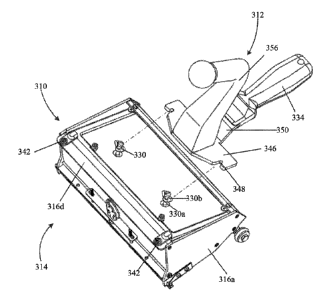
[0034] FIGS. 13-15 illustrate a container or finisher box 310 according to
a fourth
embodiment of the invention that includes a removable handle assembly or
accessory 312. The
finisher box 310 and the handle assembly 312 of FIGS. 12-15 have similar
structure to that of the
finisher box 10 and the handle assembly 12 of FIGS. 1-4. Therefore, structure
of the fourth
embodiment similar to the first embodiment will be identified with reference
numerals of the
first embodiment plus "300." As the fourth embodiment is also similar to the
third embodiment,
only the differences between the third and fourth embodiments will be
discussed herein.
[0035] FIGS. 12-15 illustrate the connector plate 346 including the first
edge 347a, the
second edge 347b parallel to the first edge 347a, and an extension 350. The
extension 350
7702329 8
Date Recue/Date Received 2022-08-05
includes a first end 352 and a second end 354. The first end 352 is coupled to
the connector
plate 346, whereas the second end 354 couples to and extends into the first
handle 334.
[0036] FIGS. 12-15 illustrate a second handle 356 in place of the push post
36. Similar to
above, the second handle 356 and the first handle 334 may also be attached to
one another or to
the connector plate 346 or the extension 350 in one of the ways as described
above and below, or
in other ways not described within.
[0037] The second handle 356 resembles a "seven" in shape and includes a
vertical portion
358, a first angled portion 360, and a second angled portion 362 that defines
the second gripping
portion. The vertical portion 358, similar to the push post 236 of the third
embodiment, extends
substantially orthogonal to the connector plate 346. Therefore, when pressure
is applied to the
second handle 356, force is exerted orthogonally to the connector plate 346.
The first angled
portion 360 includes a longitudinal axis and extends from the vertical portion
358 partially in the
same direction that the vertical portion 358 extends (i.e., away from the
connector plate 346), but
also toward the first handle 334. In FIGS. 12-14, the second angled portion
362 includes a
longitudinal axis and extends from the first angled portion 360 away from the
first handle 334,
such that the longitudinal axis of the first angled portion 360 and the
longitudinal axis of the
second angled portion 362 intersect to form an acute angle. The second angled
portion 362 may
extend from the first angled portion 358 as illustrated in FIGS. 12-15, i.e.,
either slightly away
from the connecter plate 346, or it may be substantially parallel to the
connector plate 346. The
second angled portion 362 may also include a knob 364 at an end of the second
angled portion
362 away from the first angled portion 360.
[0038] Some operators may prefer the second handle 356 extend toward the
first handle 334,
as shown in FIG. 15, as opposed to the first orientation illustrated in FIGS.
12-14. Therefore, to
allow the operator's preference, the second handle 356 is capable of being
reversed. FIG. 15
illustrates the second handle 356 rotated 180 degrees compared to the second
handle 356 shown
in FIGS. 12-14. In the preferred embodiment, the second handle 356 includes
four threaded
openings (not shown) which at least partially extend through the vertical
portion 358 and may
further extend into the first angled portion 360. The connector plate 346 also
includes four holes
(not shown) that substantially align with the openings of the second handle
356. Four threaded
7702329 9
Date Recue/Date Received 2022-08-05
fasteners (not shown) extend through the holes of the connector plate 346 and
into the openings
of the second handle 356. The fasteners are tightened to secure the second
handle 356 to the
connector plate 346. Therefore, when the fasteners are removed, the second
handle 356 may be
reoriented and refastened to the connector plate 346 in a different operator's
preferred
orientation. Although described as requiring four holes, four openings, and
four fasteners, any
number of holes, openings, and fasteners sufficient to secure the second
handle 356 to the
connector plate 346 may be used. Similarly, the second handle 356 may be
rotated either less or
more than 180 degrees and secured by other methods not described within. Those
other methods
may provide possibilities of orientating and securing the second handle 356 in
a manner not
illustrated in FIGS. 12-15.
[0039] In reference to the four embodiments, the length of the first handle
34, 134, 234, 334
can vary greatly depending on the operator's preference. The end of the first
handle 34, 134,
234, 334 may include an attachment (not shown) configured to attach an
extension pole. The
extension pole would allow an operator to use the finisher box 10, 110, 210,
310 in difficult to
reach places, such as ceilings. The embodiments illustrated show a first
handle 34, 134, 234, 334
that has a relatively short length, however, embodiments not shown may include
a first handle
design 34, 134, 234, 334 that has a much greater length allowing an operator
to reach ceilings, or
the other difficult areas, without the use of the extension.
[0040] Other handle shapes and connections other than those illustrated
herein, which may
have various amounts of flexibility (and means of achieving that flexibility),
as well as rigid
connections, may be used. For example, the first handle 34, 134, 234, 334
could be thinner and
longer, similar to handles used on many garden tools. The push post 36, 136,
236 could be
removable or have a variety of shapes, similar to that shown in FIGS. 12-15
and described
above. For example, the rounded flat distal end of the push post 36, 136, 236
shown herein
could be replaced by many other possible shapes.
[0041] Various features and advantages of the invention are set forth in
the following claims.
7702329 10
Date Recue/Date Received 2022-08-05