Note: Descriptions are shown in the official language in which they were submitted.
1
ACTIVELY CONTROLLABLE STENT, STENT GRAFT, HEART VALVE AND METHOD
OF CONTROLLING SAME
Technical Field
The present invention lies in the field of stents, stent grafts, heart valves
(including
aortic, pulmonary, mitral and tricuspid), and methods and systems for
controlling and implanting
stents, stent grafts and heart valves.
Medical and surgical implants are placed often in anatomic spaces where it is
desirable
for the implant to conform to the unique anatomy of the targeted anatomic
space and secure a
seal therein, preferably without disturbing or distorting the unique anatomy
of that targeted
anatomic space.
While the lumens of most hollow anatomic spaces are ideally circular, in fact,
the
cross-sectional configurations of most anatomic spaces are, at best, ovoid,
and may be highly
irregular. Such lumenal irregularity may be due to anatomic variations and/or
to pathologic
conditions that may change the shape and topography of the lumen and its
associated anatomic
wall. Examples of anatomic spaces where such implants may be deployed include,
but are not
limited to, blood vessels, the heart, other vascular structures, vascular
defects (such as thoracic
and abdominal aortic aneurysms), the trachea, the oropharynx, the esophagus,
the stomach, the
duodenum, the ileum, the jejunum, the colon, the rectum, ureters, urethras,
fallopian tubes,
biliary ducts, pancreatic ducts, or other anatomic structures containing a
lumen used for the
transport of gases, blood, or other liquids or liquid suspensions within a
mammalian body.
For a patient to be a candidate for existing endograft methods and
technologies, to
permit an adequate seal, a proximal neck of, ideally, at least 12 mm of normal
aorta must exist
downstream of the left subclavian artery for thoracic aortic aneurysms or
between the origin of
the most inferior renal artery and the origin of the aneurysm in the case of
abdominal aneurysms.
Similarly, ideally, at least 12 mm of normal vessel must exist distal to the
distal extent of the
aneurysm for an adequate seal to be achieved. The treatment of Aortic Stenosis
through
Transcather Aortic Valve Replacement (TAVR) is becoming more common. The
limitations of
current TAVR techniques do not allow for repositioning of the implant once it
has been deployed
in place. Further, the final expanded diameter of the current devices is fixed
making presizing a
critical and difficult step.
Date Regue/Date Received 2022-08-12
2
Migration of existing endografts has also been a significant clinical problem,
potentially causing leakage and profusion of aneurysms and/or compromising
necessary vascular
supplies to arteries such as the coronary, carotid, subclavian, renal, or
internal iliac vessels. This
problem only has been addressed partially by some existing endograft designs,
in which barbs or
.. hooks have been incorporated to help retain the endograft at its intended
site. However, most
existing endograft designs are solely dependent on radial force applied by
varying length of stent
material to secure a seal against the recipient vessel walls.
Because of the limitations imposed by existing vascular endograft devices and
endovascular techniques, a significant number of abdominal and thoracic
aneurysms repaired in
the U.S. are still managed though open vascular surgery, instead of the lower
morbidity of the
endovascular approach.
Pre-sizing is required currently in all prior art endografts. Such pre-sizing
based on
CAT-scan measurements is a significant problem. This leads, many times, to mis-
sized grafts.
In such situations, more graft segments are required to be placed, can require
emergency open
.. surgery, and can lead to an unstable seal and/or migration. Currently there
exists no endograft
that can be fully repositioned after deployment.
Thus, a need exists to overcome the problems with the prior art systems,
designs, and
processes as discussed above.
Disclosure of Invention
The invention provides surgical implant devices and methods for their
manufacture and
use that overcome the hereinafore-mentioned disadvantages of the heretofore-
known devices and
methods of this general type and that provide such features with improvements
that increase the
ability of such an implant to be precisely positioned and sealed, with better
in situ
accommodation to the local anatomy of the targeted anatomic site. The
invention provide an
adjustment tool that can remotely actuate an adjustment member(s) that causes
a configuration
change of a portion(s) of an implant, which configuration change includes but
is not limited to
diameter, perimeter, shape, and/or geometry or a combination of these, to
create a seal and
provide retention of an implant to a specific area of a target vessel or
structure even when the
cross-sectional configuration of the anatomic space is non-circular, ovoid, or
irregular.
Date Regue/Date Received 2022-08-12
3
The invention provides an actively controllable stent, stent graft, stent
graft assembly,
heart valve, and heart valve assembly, and methods and systems for controlling
and implanting
such devices that overcome the hereinafore-mentioned disadvantages of the
heretofore-known
devices and methods of this general type and that provide such features with
control both in
.. opening and closing and in any combination thereof even during a surgical
procedure or after
completion of a surgical procedure.
One exemplary aspect of the present invention is directed towards novel
designs for
endovascular implant grafts, and methods for their use for the treatment of
aneurysms (e.g.,
aortic) and other structural vascular defects. An endograft system for
placement in an anatomic
structure or blood vessel is disclosed in which an endograft implant
comprises, for example, a
non-elastic tubular implant body with at least an accommodating proximal end.
Accommodating, as used herein, is the ability to vary a configuration in one
or more ways,
which can include elasticity, expansion, contraction, and changes in geometry.
Both or either of
the proximal and distal ends in an implant according to the present invention
further comprise
one or more circumferential expandable sealable collars and one or more
expandable sealing
devices, capable of being expanded upon deployment to achieve the desired seal
between the
collar and the vessel's inner wall. Exemplary embodiments of such devices can
be found in co-
pending U.S. Patent Application Serial Nos. 11/888,009, filed July 31, 2007,
and 12/822,291,
filed June 24, 2010, which applications have been incorporated herein in their
entireties. Further
embodiments of endovascular implants and delivery systems and methods
according to the
present invention may be provided with retractable retention tines or other
retention devices
allowing an implant to be repositioned before final deployment. In other
embodiments, the
implant can be repositioned after final deployment. An endograft system
according to the
present invention further comprises a delivery catheter with an operable
tubular sheath capable
of housing a folded or compressed endograft implant prior to deployment and
capable of
retracting or otherwise opening in at least its proximal end to allow implant
deployment. The
sheath is sized and configured to allow its placement via a peripheral
arteriotomy site, and is of
appropriate length to allow its advancement into, for example, the aortic
valve annulus,
ascending aorta, aortic arch, and thoracic or abdominal aorta, as required for
a specific
application. Sheath movement is provided in a novel manner by manual actuation
and/or
automatic actuation.
Date Regue/Date Received 2022-08-12
4
While some post-implantation remodeling of the aortic neck proximal to an
endovascular graft (endograft) has been reported, existing endograft
technology does not allow
for the management of this condition without placement of an additional
endograft sleeve to
cover the remodeled segment. Exemplary prostheses of the present invention as
described herein
allow for better accommodation by the implant of the local anatomy, using an
actively controlled
expansion device for the sealing interface between the prosthesis collar and
the recipient vessel's
inner wall. Furthermore, exemplary prostheses of the present invention as
disclosed herein are
provided with a controllably releasable disconnect mechanism that allows
remote removal of an
adjustment tool and locking of the retained sealable mechanism after
satisfactory positioning and
sealing of the endograft. In some exemplary embodiments according to the
present invention,
the controllably releasable disconnect mechanism may be provided in a manner
that allows post-
implantation re-docking of an adjustment member to permit post-implantation
repositioning
and/or resealing of a prostheses subsequent to its initial deployment.
Certain aspects of the present invention are directed towards novel designs
for sealable
endovascular implant grafts and endovascular implants, and methods for their
use for the
treatment of aortic aneurysms and other structural vascular defects and/or for
heart valve
replacements. Various embodiments as contemplated within the present invention
may include
any combination of exemplary elements as disclosed herein or in the co-pending
patent
applications referenced above.
In an exemplary embodiment according to the present invention, a sealable
vascular
endograft system for placement in a vascular defect is provided, comprising an
elongated main
implant delivery catheter with an external end and an internal end for
placement in a blood vessel
with internal walls. In such an exemplary embodiment, the main implant
delivery catheter
further comprises a main implant delivery catheter sheath that may be openable
or removable at
the internal end and a main implant delivery catheter lumen containing within
a compressed or
folded endovascular implant. Further, an endovascular implant comprises a non-
elastic tubular
implant body with an accommodating proximal end terminating in a proximal
sealable
circumferential collar that may be expanded by the operator to achieve a fluid-
tight seal between
the proximal sealable circumferential collar and the internal walls of the
blood vessel proximal to
the vascular defect. Moreover, an endovascular implant may further comprise a
non-elastic
tubular implant body with an accommodating distal end terminating in a distal
sealable
Date Regue/Date Received 2022-08-12
5
circumferential collar controlled by a distal variable sealing device, which
may be expanded by
the operator to achieve a fluid-tight seal between the distal sealable
circumferential collar and the
internal walls of the blood vessel distal to the vascular defect.
In a further exemplary embodiment according to the present invention, an
implant
interface is provided for a sealable attachment of an implant to a wall within
the lumen of a
blood vessel or other anatomic conduit.
In a yet further exemplary embodiment according to the present invention, an
implant
gasket interface is provided for a sealable attachment of an implant to a wall
within the lumen of
a blood vessel or other anatomic conduit, wherein the sealable attachment
provides for auto-
adjustment of the seal while maintaining wall attachment to accommodate post-
implantation wall
remodeling.
Still other exemplary embodiments of endografts and endograft delivery systems
according to the present invention serve as universal endograft cuffs, being
first placed to offer
their advantageous anatomic accommodation capabilities, and then serving as a
recipient vessel
for other endografts, including conventional endografts.
Furthermore, exemplary embodiments of endografts and endograft delivery
systems
according to the present invention may be provided with a mechanism to permit
transfer of
torque or other energy from a remote operator to an adjustment member
comprising a sealable,
adjustable circumferential assembly controlled by an adjustment tool, which
may be detachable
therefrom and may further cause the assembly to lock upon detachment of the
tool. In some
exemplary embodiments of the present invention, the variable sealing device
may be provided
with a re-docking element that may be recaptured by subsequent operator
interaction, allowing
redocking and repositioning and/or resealing of the endograft at a time after
its initial
deployment.
Moreover, the various exemplary embodiments of the present invention as
disclosed
herein may constitute complete endograft systems, or they may be used as
components of a
universal endograft system as disclosed in co-pending patent applications that
may allow the
benefits of the present invention to be combined with the ability to receive
other endografts.
Additionally, the present invention encompasses sealable devices that may be
used in
other medical devices such as adjustable vascular cannulas or other medical or
surgical devices
or implants, such as heart valves.
Date Regue/Date Received 2022-08-12
6
With the foregoing and other objects in view, there is provided, in accordance
with the
invention, a surgical implant including an implant body and a selectively
adjustable assembly
attached to the implant body, having adjustable elements, and operable to
cause a configuration
change in a portion of the implant body and, thereby, permit implantation of
the implant body
within an anatomic orifice to effect a seal therein under normal physiological
conditions.
Although the invention is illustrated and described herein as embodied in an
actively
controllable stent, stent graft, stent graft assembly, heart valve, and heart
valve assembly, and
methods and systems for controlling and implanting such devices, it is,
nevertheless, not
intended to be limited to the details shown because various modifications and
structural changes
may be made therein without departing from the spirit of the invention and
within the scope and
range of equivalents of the claims. Additionally, well-known elements of
exemplary
embodiments of the invention will not be described in detail or will be
omitted so as not to
obscure the relevant details of the invention.
Additional advantages and other features characteristic of the present
invention will be
set forth in the detailed description that follows and may be apparent from
the detailed
description or may be learned by practice of exemplary embodiments of the
invention. Still other
advantages of the invention may be realized by any of the instrumentalities,
methods, or
combinations particularly pointed out in the claims.
Other features that are considered as characteristic for the invention are set
forth in the
appended claims. As required, detailed embodiments of the present invention
are disclosed
herein; however, it is to be understood that the disclosed embodiments are
merely exemplary of
the invention, which can be embodied in various forms. Therefore, specific
structural and
functional details disclosed herein are not to be interpreted as limiting, but
merely as a basis for
the claims and as a representative basis for teaching one of ordinary skill in
the art to variously
employ the present invention in virtually any appropriately detailed
structure. Further, the terms
and phrases used herein are not intended to be limiting; but rather, to
provide an understandable
description of the invention. While the specification concludes with claims
defining the features
of the invention that are regarded as novel, it is believed that the invention
will be better
understood from a consideration of the following description in conjunction
with the drawing
figures, in which like reference numerals are carried forward.
Date Regue/Date Received 2022-08-12
7
Brief Description of Drawings
The accompanying figures, where like reference numerals refer to identical or
functionally similar elements throughout the separate views, which are not
true to scale, and
which, together with the detailed description below, are incorporated in and
form part of the
specification, serve to illustrate further various embodiments and to explain
various principles
and advantages all in accordance with the present invention. Advantages of
embodiments of the
present invention will be apparent from the following detailed description of
the exemplary
embodiments thereof, which description should be considered in conjunction
with the
accompanying drawings in which:
FIG. 1 is a fragmentary, partially longitudinally cross-sectional, side
elevational view
of an exemplary embodiment of an actively controllable stent/stent graft
deployment system of
the present invention in a non-deployed state with a front half of the outer
catheter removed;
FIG. 2 is a fragmentary, side elevational view of an enlarged distal portion
of the stent
deployment system of FIG. 1;
FIG. 3 is a fragmentary, perspective view of the stent deployment system of
FIG. 1
from above the distal end;
FIG. 4 is a fragmentary, perspective view of the stent deployment system of
FIG. 1
from above the distal end with the system in a partially deployed state;
FIG. 5 is a fragmentary, side elevational view of the stent deployment system
of FIG. 2
in a partially deployed state;
FIG. 6 is a is a top plan view of a drive portion of the stent deployment
system of FIG.
2;
FIG. 7 is a fragmentary, longitudinally cross-sectional view of a rear half of
the stent
deployment system of FIG. 6;
FIG. 8 is a fragmentary, perspective view of the stent deployment system of
FIG. 6;
FIG. 9 is a fragmentary, perspective view of the stent deployment system of
FIG. 1
from above the distal end with the system in an expanded state and with the
assembly-fixed
needles in an extended state;
FIG. 10 is a fragmentary, longitudinal cross-sectional view of the stent
deployment
system of FIG. 11 showing the rear half in a partially expanded state of the
stent lattice;
Date Regue/Date Received 2022-08-12
8
FIG. 11 is a fragmentary, longitudinal cross-sectional view of the stent
deployment
system of FIG. 10 showing the front half in a further expanded state;
FIG. 12 is a fragmentary, longitudinal cross-sectional view of the stent
deployment
system of FIG. 11 with a deployment control assembly in a partially disengaged
state;
FIG. 13 is a fragmentary, longitudinally cross-sectional view of the stent
deployment
system of FIG. 12 with the deployment control assembly in a disengaged state;
FIG. 14 is a fragmentary, longitudinally cross-sectional view of an enlarged
portion of
the stent deployment system of FIG. 12 in the partially disengaged state;
FIG. 15 is a fragmentary, longitudinally cross-sectional view of an enlarged
portion of
the stent deployment system of FIG. 13 in a disengaged state;
FIG. 16 is a fragmentary, partially cross-sectional, side elevational view of
the stent
deployment system of FIG. 9 rotated about a longitudinal axis, with the
deployment control
assembly in the disengaged state, and showing a cross-section of a portion of
the deployment
control assembly;
FIG. 17 is a fragmentary, longitudinally cross-sectional view of the stent
deployment
system of FIG. 16 showing a cross-section of a drive portion of a stent
assembly with a fixed
needle;
FIG. 18 is a fragmentary, perspective view of the stent deployment system of
FIG. 16;
FIG. 19 is a fragmentary, perspective view of an enlarged portion of the stent
deployment system of FIG. 18;
FIG. 20 is a fragmentary, perspective view of the stent deployment system of
FIG. 18
with a diagrammatic illustration of paths of travel of strut crossing points
as the stent is moved
between its expanded and contracted states;
FIG. 21 is a fragmentary, side elevational view from an outer side of an
alternative
exemplary embodiment of a jack assembly according to the invention in a stent-
contracted state
with a drive sub-assembly in a connected state and with a needle sub-assembly
in a retracted
state;
FIG. 22 is a fragmentary, cross-sectional view of the jack assembly of FIG.
21;
FIG. 23 is a fragmentary, cross-sectional view of the jack assembly of FIG. 21
in a
partially stent-expanded state;
Date Regue/Date Received 2022-08-12
9
FIG. 24 is a fragmentary, cross-sectional view of the jack assembly of FIG. 23
with a
needle pusher in a partially actuated state before extension of the needle;
FIG. 25 is a fragmentary, cross-sectional view of the jack assembly of FIG. 24
with the
needle pusher in another partially actuated state with the needle pusher in
another partially
actuated state with an extension of the needle;
FIG. 26 is a fragmentary, cross-sectional view of the jack assembly of FIG. 25
with the
drive sub-assembly in a partially disconnected state without retraction of the
needle pusher;
FIG. 27 is a fragmentary, cross-sectional view of the jack assembly of FIG. 26
with the
drive sub-assembly in a further partially disconnected state with partial
retraction of the needle
pusher;
FIG. 28 is a fragmentary, cross-sectional view of the jack assembly of FIG. 27
with the
drive sub-assembly in a still a further partially disconnected state with
further retraction of the
needle pusher;
FIG. 29 is a fragmentary, cross-sectional view of the jack assembly of FIG. 23
with the
drive sub-assembly and the needle pusher in a disconnected state;
FIG. 30 is a fragmentary, cross-sectional view of another alternative
exemplary
embodiment of a jack assembly according to the invention in a stent-contracted
state with a drive
sub-assembly in a connected state and with a needle sub-assembly in a
retracted state;
FIG. 31 is a fragmentary, cross-sectional view of the jack assembly of FIG. 30
in a
partially stent-expanded state;
FIG. 32 is a fragmentary, cross-sectional view of the jack assembly of FIG. 31
with the
needle sub-assembly in an actuated state with extension of the needle;
FIG. 33 is a fragmentary, cross-sectional view of the jack assembly of FIG. 32
with the
drive sub-assembly in a disconnected state and the needle sub-assembly in a
disconnected state;
FIG. 34 is a fragmentary, perspective view of the jack assembly of FIG. 33
with the
extended needle rotated slightly to the right of the figure.
FIG. 35 is a fragmentary, perspective view of the jack assembly of FIG. 34
rotated to
the right by approximately 45 degrees;
FIG. 36 is a fragmentary, partially cross-sectional, perspective view from
above the
jack assembly of FIG. 30 showing the interior of the distal drive block;
Date Regue/Date Received 2022-08-12
10
FIG. 37 is a fragmentary, enlarged, cross-sectional view of the jack assembly
of FIG.
33;
FIG. 38 is a photograph of a perspective view from above the upstream end of
another
exemplary embodiment of an actively controllable stent graft according to the
invention in a
substantially contracted state;
FIG. 39 is a photograph of a perspective view of the stent graft of FIG. 38 in
a partially
expanded state;
FIG. 40 is a photograph of a perspective view of the stent graft of FIG. 38 in
an
expanded state;
FIG. 41 is a photograph of a side perspective view of the stent graft of FIG.
38 in an
expanded state;
FIG. 42 is a photograph of a perspective view of another exemplary embodiment
of an
actively controllable stent for a stent graft according to the invention in a
substantially expanded
state with integral upstream anchors;
FIG. 43 is a photograph of a perspective view of the stent of FIG. 42 in a
partially
expanded state;
FIG. 44 is a photograph of a perspective view of the stent of FIG. 42 in
another
partially expanded state;
FIG. 45 is a photograph of a perspective view of the stent of FIG. 42 in a
substantially
contracted state;
FIG. 46 is a photograph of a side perspective view of another exemplary
embodiment
of an actively controllable stent for a stent graft according to the invention
in a substantially
expanded state with a tapered outer exterior;
FIG. 47 is a photograph of a top perspective view of the stent of FIG. 46;
FIG. 48 is a photograph of a perspective view of the stent of FIG. 46 from
above a side;
FIG. 49 is a photograph of a perspective view of the stent of FIG. 46 from
above a side
with the stent in a partially expanded state;
FIG. 50 is a photograph of a perspective view of the stent of FIG. 46 from
above a side
with the stent in a substantially contracted state;
FIG. 51 is a photograph of an exemplary embodiment of a low-profile joint
assembly
for actively controllable stents/stent grafts according to the invention;
Date Regue/Date Received 2022-08-12
11
FIG. 52 is a photograph of struts of the joint assembly of FIG. 51 separated
from one
another;
FIG. 53 is a photograph of a rivet of the joint assembly of FIG. 51;
FIG. 54 is a fragmentary, side perspective view of another exemplary
embodiment of
an actively controllable stent system for a stent graft according to the
invention in a substantially
expanded state with a tapered outer exterior;
FIG. 55 is a side perspective view of the stent system of FIG. 54;
FIG. 56 is a side elevational view of the stent system of FIG. 54;
FIG. 57 is a side elevational view of the stent system of FIG. 54 in a
substantially
contracted state;
FIG. 58 is a side elevational view of another exemplary embodiment of a
portion of an
actively controllable stent system for a stent graft according to the
invention in a substantially
contracted state;
FIG. 59 is a perspective view of the stent system portion of FIG. 58;
FIG. 60 is a top plan view of the stent system portion of FIG. 58;
FIG. 61 is a side perspective view of the stent system portion of FIG. 58 in a
partially
expanded state;
FIG. 62 is a top plan view of the stent system portion of FIG. 61;
FIG. 63 is a side elevational view of the stent system portion of FIG. 61;
FIG. 64 is a perspective view of a downstream side of an exemplary embodiment
of a
replacement valve assembly according to the invention in an expanded state;
FIG. 65 is a side elevational view of the valve assembly of FIG. 64;
FIG. 66 is a fragmentary, perspective view of a delivery system according to
the
invention for the aortic valve assembly of FIG. 64 with the aortic valve
assembly in the process
of being implanted and in the right iliac artery;
FIG. 67 is a fragmentary, perspective view of the delivery system and aortic
valve
assembly of FIG. 66 with the aortic valve assembly in the process of being
implanted and in the
abdominal aorta;
FIG. 68 is a fragmentary, perspective view of the delivery system and aortic
valve
assembly of FIG. 66 with the aortic valve assembly in the process of being
implanted and being
adjacent the aortic valve implantation site;
Date Regue/Date Received 2022-08-12
12
FIG. 69 is a fragmentary, perspective view of the delivery system and aortic
valve
assembly of FIG. 66 with the aortic valve assembly implanted in the heart;
FIG. 70 is a fragmentary, enlarged, perspective view of the delivery system
and the
aortic valve assembly of FIG. 69 implanted at an aortic valve implantation
site;
FIG. 71 is a perspective view of a side of another exemplary embodiment of a
replacement aortic valve assembly according to the invention in an expanded
state with the graft
material partially transparent;
FIG. 72 is a perspective view of the replacement aortic valve assembly of FIG.
71 from
above a downstream side thereof;
FIG. 73 is a perspective view of the replacement aortic valve assembly of FIG.
71 from
above a downstream end thereof;
FIG. 74 is a perspective view of the replacement aortic valve assembly of FIG.
71 from
below an upstream end thereof;
FIG. 75 is a perspective view of an enlarged portion of the replacement aortic
valve
assembly of FIG. 74;
FIG. 76 is a perspective view of the replacement aortic valve assembly of FIG.
71 from
a side thereof with the graft material removed;
FIG. 77 is a perspective view of the replacement aortic valve assembly of FIG.
76 from
above a downstream side thereof;
FIG. 78 is a side elevation, vertical cross-sectional view of the replacement
aortic valve
assembly of FIG. 76;
FIG. 79 is a perspective view of the replacement aortic valve assembly of FIG.
76 from
a side thereof with the valve material removed, with the stent lattice in an
expanded state;
FIG. 80 is a perspective view of the replacement aortic valve assembly of FIG.
79 with
the stent lattice in an intermediate expanded state;
FIG. 81 is a perspective view of the replacement aortic valve assembly of FIG.
79 with
the stent lattice in an almost contracted state;
FIG. 82 is a downstream plan view of the replacement aortic valve assembly of
FIG. 79
in an intermediate expanded state;
FIG. 83 is an enlarged downstream plan view of a portion of the replacement
aortic
valve assembly of FIG. 79 in an expanded state;
Date Regue/Date Received 2022-08-12
13
FIG. 84 is a side elevational view of the replacement aortic valve assembly of
FIG. 79
in an expanded state, with graft material removed, and with distal portions of
an exemplary
embodiment of a valve delivery system;
FIG. 85 is a perspective view of an exemplary embodiment of a jack assembly of
the
replacement aortic valve assembly of FIG. 84 from a side thereof with the
valve delivery system
sectioned;
FIG. 86 is a perspective view of the replacement aortic valve assembly of FIG.
79 in an
expanded state, with graft material removed, and with distal portions of
another exemplary
embodiment of a valve delivery system;
FIG. 87 is a fragmentary, enlarged perspective view of the replacement aortic
valve
assembly of FIG. 86 with graft material shown;
FIG. 88 is a fragmentary, enlarged, perspective view of the delivery system
and the
aortic valve assembly of FIG. 71 implanted at an aortic valve implantation
site;
FIG. 89 is a fragmentary, side elevational view of another exemplary
embodiment of an
actively controllable and tiltable stent graft system according to the
invention in a partially
expanded state and a non-tilted state;
FIG. 90 is a fragmentary, side elevational view of the system of FIG. 89 in a
partially
tilted state from a front thereof;
FIG. 91 is a fragmentary, side elevational view of the system of FIG. 90 in
another
partially tilted state;
FIG. 92 is a fragmentary, side elevational view of the system of FIG. 90 in
yet another
partially tilted state;
FIG. 93 is a fragmentary, perspective view of the system of FIG. 90 in yet
another
partially tilted state;
FIG. 94 is a fragmentary, partially cross-sectional, side elevational view of
another
exemplary embodiment of an actively controllable and tiltable stent graft
system according to the
invention in an expanded state and a partially front-side tilted state
FIG. 95 is a fragmentary, perspective view of the system of FIG. 94 in a non-
tilted
state;
FIG. 96 is a fragmentary, side elevational view of the system of FIG. 94 in a
non-tilted
state;
Date Regue/Date Received 2022-08-12
14
FIG. 97 is a fragmentary, side elevational view of the system of FIG. 96
rotated
approximately 90 degrees with respect to the view of FIG. 96;
FIG. 98 is a fragmentary, longitudinally cross-sectional, side elevational
view of the
system of FIG. 94 showing the rear half of the system and a tubular graft
material in a non-tilted
state and partially expanded state;
FIG. 99 is fragmentary, partially cross-sectional, perspective view of the
system of FIG.
94 showing the rear half of the tubular graft material and in a non-tilted
state and a partially
expanded state;
FIG. 100 is a fragmentary, partially cross-sectional, side elevational view of
the system
of FIG. 94 showing the rear half of graft material for a bifurcated vessel and
in a non-tilted state;
FIG. 101 is a fragmentary, partially cross-sectional, side elevational view of
the system
of FIG. 100 in an expanded state and a partially tilted state;
FIG. 102 is a fragmentary, partially cross-sectional, side elevational view of
the system
of FIG. 101 rotated approximately 45 degrees with respect to the view of FIG.
101;
FIG. 103 is a fragmentary, side perspective view of another exemplary
embodiment of
an actively controllable stent graft system according to the invention in an
expanded state;
FIG. 104 is a fragmentary, side elevational view of the system of FIG. 103;
FIG. 105 is a fragmentary, front elevational and partially cross-sectional
view of a self-
contained, self-powered, actively controllable stent graft delivery and
integral control system
according to the invention with the prosthesis in an expanded state with the
graft material in
cross-section showing a rear half thereof;
FIG. 106 is a perspective view of the control portion of the system of FIG.
105 as a
wireless sub-system;
FIG. 107 is a fragmentary, front elevational view of another exemplary
embodiment of
a self-contained, self-powered, actively controllable stent graft delivery and
separate tethered
control system according to the invention with different controls and with the
prosthesis in an
expanded state;
FIG. 108 is a fragmentary, perspective view of a control handle of an
exemplary
embodiment of a self-contained, self-powered, actively controllable prosthesis
delivery device
according to the invention from above a left side thereof with the upper
handle half and power
pack removed;
Date Regue/Date Received 2022-08-12
15
FIG. 109 is a fragmentary, vertically cross-sectional view of the handle of
FIG. 108
with the power pack removed;
FIG. 110 is a fragmentary, enlarged, vertically cross-sectional and
perspective view of a
sheath-movement portion of the handle of FIG. 108 from above a left side
thereof;
FIG. 111 is a fragmentary, further enlarged, vertically cross-sectional view
of the
sheath-movement portion of FIG. 110 from below a left side thereof;
FIG. 112 is a fragmentary, enlarged, vertically cross-sectional view of a
power portion
of the handle of FIG. 108 viewed from a proximal side thereof;
FIG. 113 is a fragmentary, perspective view of a needle control portion of the
handle of
FIG. 108 from above a distal side with the upper handle half and power pack
removed and with
the needle control in a lattice-contracted and needle-stowed position;
FIG. 114 is a fragmentary, perspective view of the needle control portion of
the handle
of FIG. 113 with the needle control in a lattice-expanded and needle-stowed
position;
FIG. 115 is a fragmentary, perspective view of the needle control portion of
the handle
of FIG. 114 with the needle control in a needle-extended position;
FIG. 116 is a fragmentary, perspective view of an engine portion of the handle
of FIG.
108 from above a left side thereof with the upper handle half removed;
FIG. 117 is a fragmentary, enlarged, vertically cross-sectional view of the
engine
portion of FIG. 116 viewed from a proximal side thereof;
FIG. 118 is a fragmentary, enlarged, vertically cross-sectional view of the
engine
portion of the handle portion of FIG. 117 viewed from a distal side thereof;
FIG. 119 is a flow diagram of an exemplary embodiment of a procedure for
implanting
an abdominal aorta prosthesis according to the invention;
FIG. 120 is a perspective view of an exemplary embodiment of a self-
expanding/forcibly-expanding lattice of an implantable stent assembly having
nine lattice
segments in a native, self-expanded position with jack screw assemblies
disposed between
adjacent pairs of repeating portions of the lattice, with jack screws through
a wall of the lattice,
and with each jack screw backed out in a thread-non-engaged state to allow
crimp of lattice for
loading into a stent delivery system;
FIG. 121 is a perspective view of the lattice of FIG. 120 in a
contracted/crimped state
for loading into the stent delivery system with each jack screw in a thread-
non-engaged state;
Date Regue/Date Received 2022-08-12
16
FIG. 122 is a perspective view of the lattice of FIG. 121 after being allowed
to return to
the native position of the lattice in a deployment site with each jack screw
in a thread-engaged
state for further outward expansion or inward contraction of the lattice;
FIG. 123 is a perspective view of the lattice of FIG. 122 partially expanded
from the
state shown in FIG. 122 with each jack screw in a thread-engaged state for
further outward
expansion or inward contraction of the lattice;
FIG. 124 is a tilted perspective view of the lattice of FIG. 123 partially
expanded from
the state shown in FIG. 123 with each jack screw in a thread-engaged state for
further outward
expansion or inward contraction of the lattice;
FIG. 125 is a perspective view of the lattice of FIG. 124 further expanded
near a
maximum expansion of the lattice with each jack screw in a thread-engaged
state;
FIG. 126 is a fragmentary, enlarged perspective and longitudinal cross-
sectional view
of a portion of two adjacent halves of repeating portions of an alternative
exemplary embodiment
of a self-expanding/forcibly-expanding lattice of an implantable stent
assembly with a separate
jack screw assembly connecting the two adjacent halves and with a lattice-
disconnect tube of a
stent delivery system in an engaged state covering a pair of drive screw
coupler parts therein and
with the jack screw in a thread-engaged state for further outward expansion or
inward
contraction of the lattice;
FIG. 127 is a fragmentary, further enlarged portion of the two adjacent halves
of the
repeating portions and intermediate jack screw assembly of FIG. 125 with the
disconnect tube in
a disengaged state with respect to the pair of drive screw coupler parts;
FIG. 128 is a fragmentary enlarged portion of the two adjacent halves of the
repeating
portions and intermediate jack screw assembly of FIG. 125 with the disconnect
tube in a
disengaged state and with the pair of drive screw coupler parts disconnected
from one another;
FIG. 129 is a perspective view of another exemplary embodiment of a self-
expanding/forcibly-expanding lattice of an implantable stent assembly having
nine separate
lattice segments with an exemplary embodiment of a proximal disconnect block
of a stent
delivery system as an alternative to the disconnect tube of FIGS. 126 to 128
with the proximal
disconnect block in an engaged state covering a pair of drive screw coupler
parts therein and
with each jack screw in a thread-engaged state for further outward expansion
or inward
contraction of the lattice;
Date Regue/Date Received 2022-08-12
17
FIG. 130 is a perspective view of the lattice of Ha 129 with the proximal
disconnect
blocks of the delivery system disconnected from the lattice with the proximal
disconnect block in
a disengaged state with respect to the pair of drive screw coupler parts and
illustrating how all of
the pairs of drive screw coupler parts can be coupled for simultaneous
release;
FIG. 131 is a perspective view of another exemplary embodiment of a self-
expanding/forcibly-expanding lattice of an implantable stent assembly having
nine separate
lattice segments connected to intermediate tubes for jack screws with each
jack screw in a
thread-engaged state for further outward expansion or inward contraction of
the lattice;
FIG. 132 is a top plan view of the lattice of FIG. 131;
FIG. 133 is a perspective view of another exemplary embodiment of a self-
expanding/forcibly-expanding lattice of an implantable stent assembly having
nine lattice
segments with locally thicker sections of lattice to accommodate and connect
to non-illustrated
jack screw assemblies;
FIG. 134 is a perspective view of another exemplary embodiment of a self-
expanding/forcibly-expanding lattice of an implantable stent assembly having
nine lattice
segments with bent-over tabs for connecting to non-illustrated jack screw
assemblies;
FIG. 135 is a perspective view of another exemplary embodiment of a self-
expanding/forcibly-expanding lattice of an implantable valve assembly having
six lattice
segments in an expanded position with jack screw assemblies disposed between
adjacent pairs of
repeating portions of the lattice and having three valve leaflets and jack
screws through a wall of
the lattice in a thread-non-engaged state of the jack screw;
FIG. 136 is a plan view of the valve assembly of FIG. 135;
FIG. 137 is a plan view of the valve assembly of FIG. 135 in a partially
compressed
state of the lattice without the valve leaflets and with each jack screw in a
thread-non-engaged
state;
FIG. 138 is a perspective view of another exemplary embodiment of a self-
expanding/forcibly-expanding lattice of an implantable valve assembly having
six lattice
segments in a native, self-expanded position with jack screw assemblies
attached at an interior
surface between adjacent pairs of segments of the lattice without the valve
leaflets and with each
of the jack screws in a thread-engaged state for further outward expansion or
inward contraction
of the lattice;
Date Regue/Date Received 2022-08-12
18
FIG. 139 is a perspective view of the lattice of FIG. 138 in a
contracted/crimped state
for loading into the stent delivery system with each jack screw in a thread-
non-engaged state;
FIG. 140 is a tilted perspective view of the lattice of FIG. 138;
FIG. 141 is a perspective view of the lattice of FIG. 138 partially expanded
from the
__ state shown in FIG. 138 with each jack screw in an engaged state for
further outward expansion
or inward contraction of the lattice; and
FIG. 142 is a perspective view of the lattice of FIG. 138 further expanded
near a
maximum expansion of the lattice with each jack screw in an engaged state for
further outward
expansion or inward contraction of the lattice;
Best Mode for Carrying Out the Invention
As required, detailed embodiments of the present invention are disclosed
herein;
however, it is to be understood that the disclosed embodiments are merely
exemplary of the
invention, which can be embodied in various forms. Therefore, specific
structural and functional
__ details disclosed herein are not to be interpreted as limiting, but merely
as a basis for the claims
and as a representative basis for teaching one skilled in the art to variously
employ the present
invention in virtually any appropriately detailed structure. Further, the
terms and phrases used
herein are not intended to be limiting; but rather, to provide an
understandable description of the
invention. While the specification concludes with claims defining the features
of the invention
__ that are regarded as novel, it is believed that the invention will be
better understood from a
consideration of the following description in conjunction with the drawing
figures, in which like
reference numerals are carried forward.
Alternate embodiments may be devised without departing from the spirit or the
scope
of the invention. Additionally, well-known elements of exemplary embodiments
of the invention
__ will not be described in detail or will be omitted so as not to obscure the
relevant details of the
invention.
Before the present invention is disclosed and described, it is to be
understood that the
terminology used herein is for the purpose of describing particular
embodiments only and is not
intended to be limiting. The terms "a" or "an", as used herein, are defined as
one or more than
__ one. The term "plurality," as used herein, is defined as two or more than
two. The term
"another," as used herein, is defined as at least a second or more. The terms
"including" and/or
Date Regue/Date Received 2022-08-12
19
"having," as used herein, are defined as comprising (i.e., open language). The
term "coupled,"
as used herein, is defined as connected, although not necessarily directly,
and not necessarily
mechanically.
Relational terms such as first and second, top and bottom, and the like may be
used
solely to distinguish one entity or action from another entity or action
without necessarily
requiring or implying any actual such relationship or order between such
entities or actions. The
terms "comprises," "comprising," or any other variation thereof are intended
to cover a non-
exclusive inclusion, such that a process, method, article, or apparatus that
comprises a list of
elements does not include only those elements but may include other elements
not expressly
listed or inherent to such process, method, article, or apparatus. An element
proceeded by
"comprises
a" does not, without more constraints, preclude the existence of additional
identical elements in the process, method, article, or apparatus that
comprises the element.
As used herein, the term "about" or "approximately" applies to all numeric
values,
whether or not explicitly indicated. These temis generally refer to a range of
numbers that one of
skill in the art would consider equivalent to the recited values (i.e., having
the same function or
result). In many instances these terms may include numbers that are rounded to
the nearest
significant figure.
The terms "program," "programmed", "programming," "software," "software
application," and the like as used herein, are defined as a sequence of
instructions designed for
execution on a computer system. A "program," "software," "computer program,"
or "software
application" may include a subroutine, a function, a procedure, an object
method, an object
implementation, an executable application, an applet, a servlet, a source
code, an object code, a
shared library/dynamic load library and/or other sequence of instructions
designed for execution
on a computer system.
Herein various embodiments of the present invention are described. In many of
the
different embodiments, features are similar. Therefore, to avoid redundancy,
repetitive
description of these similar features may not be made in some circumstances.
It shall be
understood, however, that description of a first-appearing feature applies to
the later described
similar feature and each respective description, therefore, is to be
incorporated therein without
such repetition.
Date Regue/Date Received 2022-08-12
20
Described now are exemplary embodiments of the present invention. Referring
now to
the figures of the drawings in detail and first, particularly to FIGS. 1 to
19, there is shown a first
exemplary embodiment of an actively controllable stent deployment system 100
according to the
invention. Even though this exemplary embodiment is illustrated as a stent
deployment system
without the presence of a stent graft, this embodiment is not to be considered
as limited thereto.
Any stent graft embodiment according the invention as disclosed herein can be
used in this
embodiment. The stent graft is not shown in these figures for clarity.
Further, as used herein,
the terms "stent" and "stent graft" are used herein interchangeably.
Therefore, any embodiment
where a stent is described without referring to a graft should be considered
as referring to a graft
additionally or in the alternative, and any embodiment where both a stent and
a graft are
described and shown should be considered as also referring to an embodiment
where the graft is
not included.
In contrast to prior art self-expanding stents, the actively controllable
stent deployment
system 100 includes a stent lattice 110 formed by interconnected lattice
struts 112, 114. In this
exemplary embodiment, pairs of inner and outer struts 114, 112 are
respectively connected to
adjacent pairs of inner and outer struts 114, 112. More particularly, each
pair of inner and outer
struts 114, 112 are connected pivotally at a center point of each strut 114,
112. The ends of each
inner strut 114 of a pair is connected pivotally to ends of adjacent outer
struts 112 and the ends
of each outer strut 112 of a pair is connected pivotally to ends of adjacent
inner struts 114. In
such a configuration where a number of strut pairs 114, 112 are connected to
form a circle, as
shown in each of FIGS. 1 to 19, a force that tends to expand the lattice 110
radially outward will
pivot the struts 114, 112 at each pivot point and equally and smoothly expand
the entire lattice
110 from a closed state (see, e.g., FIG. 3) to any number of open states (see
FIGS. 4 to 13).
Similarly, when the stent lattice 110 is at an open state, a force that tends
to contract the stent
.. lattice 110 radially inward will pivot the struts 114, 112 at each pivot
point and equally and
smoothly contract the entire stent lattice 110 towards the closed state. This
exemplary
configuration, therefore, defines a repeating set of one intermediate and two
outer pivot points
about the circumference of the stent lattice 110. The single intermediate
pivot point 210 is, in
the exemplary embodiment shown in FIGS. 1 to 19, located at the centerpoint of
each strut 112,
114. On either side of the single intermediate pivot point 210 is a vertically
opposing pair of
outer pivot points 220.
Date Regue/Date Received 2022-08-12
21
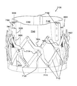
To provide such expansion and contraction forces, the actively controllable
stent
deployment system 100 includes at least one jack assembly 700 that is present
in each of FIGS. 1
to 19 but is described, first, with regard to FIG. 7. Each jack assembly 700
has a distal drive
block 710, a proximal drive block 720, and a disconnector drive block 730. A
drive screw 740
connects the distal drive block 710 to the proximal drive block 720. The drive
screw 740 has a
distal threaded drive portion 742 having corresponding threads to a threaded
drive bore 712 of
the distal drive block 710. The drive screw 740 has an intermediate unthreaded
portion 744 that
rotates freely within a smooth drive bore 722 of the proximal drive block 720.
In the
embodiment shown, the inner diameter of the smooth drive bore 722 is slightly
larger than the
outer diameter of the unthreaded portion 744 so that the unthreaded portion
744 can freely rotate
within the smooth drive bore 722 with substantially no friction. The drive
screw 740 also has an
intermediate collar 746 just proximal of the proximal drive block 720. The
outer diameter of the
intermediate collar 746 is greater than the inner diameter of the smooth drive
bore 722. Lastly,
the drive screw 740 has a proximal key portion 748 extending from the
intermediate collar 746 in
a proximal direction. The jack assembly 700 is configured to retain the drive
screw 740 within
the distal drive block 710 and the proximal drive block 720 in every
orientation of the stent
lattice 110, from the closed state, shown in FIG. 3, to a fully open state,
shown in FIG. 11, where
the distal drive block 710 and the proximal drive block 720 touch one another.
Each jack assembly 700 is attached fixedly to the stent lattice 110 at a
circumferential
location thereon corresponding to the vertically opposing pair of outer pivot
points 220. In one
exemplary embodiment of the jack assembly 700 shown in FIGS. 1 to 19, the
outer surface 714
of the distal drive block 710 and the outer surface 724 of the proximal drive
block 720 each have
a protruding boss 716, 726 having an outer shape that is able to fixedly
connect to a respective
one of the outer pivot points 220 of the stent lattice 110 but also
rotationally freely connect
thereto so that each of the inner and outer struts 114, 112 connected to the
boss 716, 726 pivots
about the boss 716, 726, respectively. In this exemplary embodiment, each boss
716, 726 is a
smooth cylinder and each outer pivot point 220 is a cylindrical bore having a
diameter
corresponding to the outer smooth surface of the cylinder but large enough to
pivot thereon
without substantial friction. The materials of the boss 716, 726 and the outer
pivot points 220 of
the inner and outer struts 114, 112 can be selected to have substantially
frictionless pivoting.
Date Regue/Date Received 2022-08-12
22
Accordingly, as the drive screw 740 rotates between the open and closed
states, the
unthreaded portion 744 of the drive screw 740 remains longitudinally stable
within the proximal
drive block 720. In contrast, the distal threaded drive portion 742
progressively enters the
threaded drive bore 712 from the proximal end to the distal end thereof as the
stent lattice 110
expands outwardly. As shown in the progressions of FIG. 2 to FIG. 4 and FIGS.
5 to 7 to 8 to 9,
as the drive screw 740 rotates within the proximal drive block 720, the distal
drive block 710
moves closer and closer to the proximal drive block 720, thereby causing a
radial expansion of
the stent lattice 110.
To implant the stent lattice 110 in a tubular anatomic structure (such as a
vessel or a
valve seat), the stent lattice 110 needs to be disconnected from the delivery
system. Delivery of
the stent lattice 110 to the anatomic structure will be described in further
detail below. When the
stent lattice 110 enters the implantation site, it will be most likely be in
the closed state shown in
FIG. 3, although for various reasons, the stent lattice 110 can be expanded
partially, if desired,
before reaching the implantation site. For purposes of explaining the
disconnect, the extent of
expansion is not relevant. When at the implantation site, the stent lattice
110 will be expanded
by rotating the drive screw 740 in a corresponding expansion direction (the
direction of threads
of the drive screw 740 and the drive bore 712 will determine if the drive
screw 740 needs to be
rotated clockwise or counter-clockwise). The stent lattice 110 is expanded to
a desired
expansion diameter, for example as shown in the progression of FIGS. 4 to 9 or
FIGS. 10 to 11,
so that it accommodates to the natural geometry of the implantation site, even
if the geometry is
non-circular or irregular. When the implantation diameter is reached, e.g., in
FIGS. 9 and 11, the
jack assemblies 700 need to be disconnected from the remainder of the stent
deployment system
100.
To accomplish disconnect of the jack assemblies 700, the disconnector drive
block 730
is provided with two lumens. A first lumen, the drive lumen 732, accommodates
a drive wire
750 that is able to rotationally engage the proximal key portion 748. In the
exemplary
embodiment shown, which is most clearly illustrated in FIG. 19, the proximal
key portion 748
has a square cross-sectional shape. A drive wire bushing 734 rotationally
freely but
longitudinally fixedly resides in the drive lumen 732. The drive wire bushing
734 is connected
to the drive wire 750 either as an integral part thereof or through a
connection sleeve 752.
Regardless of the connection design, any rotation of the drive wire 750 in
either direction will
Date Regue/Date Received 2022-08-12
23
cause a corresponding rotation of the drive wire bushing 734. A key hole 738
at the distal end of
the disconnector drive block 730 and having an internal shape corresponding to
a cross-section
of the proximal key portion 748 allows a rotationally fixed but longitudinally
free connection to
occur with the proximal key portion 748. In the exemplary embodiment shown in
FIG. 19, the
key hole 738 also has a square cross-sectional shape.
The disconnector drive block 730 also has a second lumen, a disconnect lumen
731,
which is best shown in FIGS. 14 and 16. Residing in the disconnect lumen 731
in a rotationally
free but longitudinally fixed manner is a retainer screw 760. The retainer
screw 760 has a distal
threaded portion 762, an intermediate shaft 764, and a proximal connector 766.
The distal
threaded portion 762 has an exterior thread corresponding to an internal
thread of a connect
lumen 1631, which is located in the proximal drive block 720 and is coaxial
with the disconnect
lumen 731. The intermediate shaft 764 has a smooth exterior surface and a
cross-sectional shape
that is slightly smaller than the cross-sectional shape of the disconnect
lumen 731 so that it can
be rotated freely within the disconnect lumen 731 substantially without
friction. The proximal
connector 766 has a flange with an outer diameter greater than the inner
diameter of the
disconnect lumen 731. The proximal connector 766 is connected at a proximal
end thereof to a
disconnect wire 770, which connection can either be an integral part thereof
or through a
secondary connection, such as a weld or connection sleeve.
With such a configuration of the proximal drive block 720 and the disconnector
drive
block 730 of a jack assembly 700, rotation in a securing direction will
longitudinally secure the
proximal drive block 720 to the disconnector drive block 730 so that the stent
lattice 110 remains
connected to the drive wire 750 and the disconnect wire 770. In the connected
state, the stent
lattice 110 may be extended outward and retracted inward as many times until
implantation
alignment according to the surgeon's desire. Likewise, rotation in a
disconnecting direction will
longitudinally release the proximal drive block 720 from the disconnector
drive block 730 so that
the stent lattice 110 disconnects entirely from the drive wire 750 and the
disconnect wire 770.
This process is illustrated with regard to FIGS. 10 to 19. In the exemplary
illustration
of FIG. 10, the stent lattice 110 is not fully expanded. Because the distal
threaded portion 762 of
the retainer screw 760 is threaded within the connect lumen 1631 of the
proximal drive block
720, the disconnector drive block 730 remains longitudinally fixed to the
proximal drive block
720 -- ideally, a configuration that exists from the time that the stent
deployment system 100 first
Date Regue/Date Received 2022-08-12
24
enters the patient and at least up until implantation of the stent lattice 110
occurs. Expansion of
the stent lattice 110 is finished in the configuration of FIG. 11 and, for
purposes of this example,
it is assumed that the stent lattice 110 is correctly implanted at the
implantation site. Therefore,
disconnection of the delivery system can occur. It is noted that this
implantation position just
happens to be at a circumferential extreme of the stent lattice 110 because
the distal drive block
710 and the proximal drive block 720 are touching. In actual use, however, it
is envisioned that
such touching does not occur when expanded for implantation and, in such a
state, there is a
separation distance between the distal drive block 710 and the proximal drive
block 720 to give
the stent lattice 110 room to expand into the implantation site if needed.
Disconnection of the
stent lattice 110 begins by rotating the disconnect wire 770 in a direction
that unscrews the
threaded portion 762 of the retainer screw 760 from the connect lumen 1631. As
the stent lattice
110 is implanted with expansive force at the implantation site, the
disconnector drive block 730
moves proximally as unthreading occurs. Complete unthreading of the retainer
screw 760 is
shown in FIGS. 12 and 14. In a configuration with more than one jack assembly
700 (the
configuration of FIGS. 1 to 19 has 4, for example), each disconnect wire 770,
770' will rotate
synchronously to have each disconnector drive block 730 disconnect from its
respective
proximal drive block 720 substantially simultaneously, as shown in FIG. 12.
Such synchronous
movement will be described in greater detail below. With the stent lattice 110
implanted, as
shown in FIGS. 13, 15, 18, and 19, the delivery system for the stent lattice
110 can be withdrawn
proximally away from the implantation site and be retracted out from the
patient.
It is noted that the exemplary embodiment of FIGS. 1 to 19 shows the actively
controllable stent deployment system 100 as having four jack assemblies 700
equally spaced
around the circumference of the lattice 110. This configuration is merely
exemplary and any
number of jack assemblies 700 can be used to expand and contract the lattice
110, including a
minimum of one jack assembly 700 in total and a maximum of one jack assembly
700 for each
intersection between each inner and outer strut pair 112, 114. Herein, three
and four jack
assemblies 700 are depicted and used to show particularly well performing
configurations. By
using an even number, counter-rotating screws can be used to null the torque.
FIG. 20 is provided to further explain how the stent lattice 110 moves when it
is
expanded and contracted. As set forth above, the actively controllable stent
deployment system
100 is based upon the construction of the stent lattice 110 and the attachment
of the proximal and
Date Regue/Date Received 2022-08-12
25
distal drive blocks 720, 710 of at least one jack assembly 700 to at least one
set of the vertically
opposing upper and lower pivot points 220 of the stent lattice 110. With the
exemplary
connections 716, 726 and pivot points 210, 220 shown in FIGS. 1 to 19, a
longitudinal vertical
movement of one of the proximal or distal drive blocks 720, 710 with respect
to the other will
expand or contract the stent lattice 110 as described herein. FIG. 20
illustrates with solid
cylinders 2000 a radial path of travel that each intermediate pivot point 210
will traverse as the
stent lattice 110 is moved between its expanded (e.g., FIG. 9) and contracted
(e.g., FIG. 2) states.
Because the travel path is linear, the stent lattice 110 expands and contracts
smoothly and equally
throughout its circumference.
It is noted that the struts 112, 114 shown in FIGS. 1 to 19 appear to not be
linear in
certain figures. Examples of such non-linearity are the struts in FIGS. 10 and
11. Therein, each
strut 112, 114 appears to be torqued about the center pivot point such that
one end is rotated
counter-clockwise and the other is rotated clockwise. This non-linearity can
create the hourglass
figure that will help fix the graft into an implantation annulus and to create
a satisfactory seal at
the top edge of the implant. The non-linear illustrations are merely
limitations of the computer
design software used to create the various figures of the drawings. Such non-
linear depictions
should not be construed as requiring the various exemplary embodiments to have
the rotation be
a part of the inventive struts or strut configuration. Whether or not the
various struts 112, 114
will bend, and in what way they will bend, is dependent upon the
characteristics of the material
that is used to form the struts 112, 114 and upon how the pivot joints of the
lattice 110 are
created or formed. The exemplary materials forming the struts 112, 114 and the
pivots and
methods for creating the pivots are described in further detail below. For
example, they can be
stamped, machined, coined or similar from the family of stainless steels and
cobalt chromes.
With the invention, force is applied actively for the controlled expansion of
the stent
lattice 110. It may be desirable to supplement the outwardly radial
implantation force imposed
on the wall at which the stent lattice 110 is implanted. Prior art stent
grafts have included barbs
and other similar devices for supplementing the outward forces at the
implantation site. Such
devices provide a mechanical structure(s) that impinge(s) on and/or
protrude(s) into the wall of
the implantation site and, thereby, prevent migration of the implanted device.
The systems and
methods of the invention include novel ways for supplementing the actively
applied outward
expansion force. One exemplary embodiment includes actively controllable
needles, which is
Date Regue/Date Received 2022-08-12
26
described, first, with reference to FIG. 17. In this exemplary embodiment, the
distal drive block
710 and the proximal drive block 720 contain a third lumen, a distal needle
lumen 1711 and a
proximal needle lumen 1721. Contained within both of the distal and proximal
needle lumens
1711, 1721 is a needle 1700. In an exemplary embodiment, the needle 1700 is
made of a shape
.. memory material, such as Nitinol, for example. The needle 1700 is preset
into a shape that is, for
example, shown in the upper left of FIG. 12. A portion that remains in the
distal and proximal
needle lumens 1711, 1721 after implantation of the stent lattice 110 can be
preset into a straight
shape that is shown in FIG. 17. A tissue-engaging distal portion of the needle
1700, however, is
formed at least with a curve that, when extended out of the distal drive block
710, protrudes
radially outward from the center longitudinal axis of the stent lattice 110.
In such a
configuration, as the needle 1700 extends outward, it drives away from the
outer circumferential
surface 714 (see FIG. 5) of the distal drive block 710 (i.e., towards the
viewer out from the plane
shown in FIG. 5). The needle 1700 also has a longitudinal extent that places
the distal tip 1210
within the distal needle lumen 1711 when the stent lattice 110 is in the
closed state, e.g., shown
in FIG. 2.
Deployment of the needles 1700 in each jack assembly 700 (or the number of
needles
can be any number less than the number of jack assemblies 700) is illustrated,
for example,
starting with FIG. 5. In this example, the needles 1700 in each of the four
jack assemblies 700
has a length that is shorter than the longitudinal end-to-end distance of the
proximal and distal
drive blocks 720, 710 because the needles 1700 have not yet protruded from the
distal upper
surface 612 of each distal drive block 710 even though the stent lattice 110
is partially expanded.
When the stent lattice 110 has expanded slightly further, however, as shown in
FIG. 7, the
needles 1700 begin protruding from the distal upper surface 612. As the
needles 1700 are
prebent as set forth above, the needles 1700 immediately begin bending into
the natural pre-set
curved shape. See also FIGS. 7 and 8. FIG. 10 illustrates two needles 1700
even further
extended out from the distal needle lumen 1711 (only two are shown because
this is a cross-
section showing only the rear half of the stent lattice 110). FIG. 11
illustrates two needles 1700
in a fully extended position (as the distal and proximal drive blocks 710, 720
touch one another
in the most-expanded state of the stent lattice 110). FIGS. 9, 13, 16, 17, 18,
and 21 also show the
needles 1700 in an extended or fully extended state.
Date Regue/Date Received 2022-08-12
27
How the needles 1700 each extend from the distal drive block 710 can be
explained in a
first exemplary embodiment with reference to FIG. 17. A proximal portion of
the needle 1700 is
connected fixedly inside the proximal needle lumen 1721. This can be done by
any measure, for
example, by laser welding. In contrast, the intermediate and distal portions
of the needle 1700 is
allowed to entirely freely slide within the distal needle lumen 1711. With the
length set as
described above, when the distal and proximal drive blocks 710, 720 are
separated completely,
as shown in FIG. 3, the needle 1700 resides in both distal and proximal needle
lumens 1711,
1721. As one of the distal and proximal drive blocks 710, 720 begins to move
towards the other
(as set forth above, the exemplary embodiment described with regard to these
figures has the
distal drive block 710 move towards the proximal drive block 720), the
proximal portion of the
needle 1700 remains in the proximal needle lumen 1721 but the distal portion
of the needle 1700
begins to exit the distal upper surface 612, which occurs because the
intermediate and distal
portions of the needle 1700 are slidably disposed in the distal needle lumen
1711. This
embodiment where the proximal portion of the needle 1700 is fixed in the
proximal needle
lumen 1721 is referred to herein as dependent control of the needles 1700. In
other words,
extension of the needles 1700 out from the distal needle lumen 1711 occurs
dependent upon the
relative motion of the distal and proximal drive blocks 710, 720.
Alternatively, the supplemental retention of the stent lattice 110 at the
implantation site
can occur with independent control of the needles. FIGS. 21 to 29 illustrate
such an exemplary
embodiment of a system and method according to the invention. Where similar
parts exist in this
embodiment to the dependently controlled needles 1700, like reference numerals
are used. The
jack assembly 2100 is comprised of a distal drive block 710, a proximal drive
block 720, a
disconnector drive block 730, a drive screw 740, a drive wire 750 (shown
diagrammatically with
a dashed line), a retainer screw 760, and a disconnect wire 770. Different
from the jack
assembly 700 of FIGS. 1 to 19, the jack assembly 2100 also includes a needle
2200 and a needle
pusher 2210 and both the proximal drive block 720 and the disconnector drive
block 730 each
define a co-axial third lumen therein to accommodate the needle pusher 2210.
More specifically,
the distal drive block 710 includes a first pusher lumen 2211, the proximal
drive block 720
includes a second pusher lumen 2221 and the disconnector drive block 730
includes a third
pusher lumen 2231. As described above, the retainer screw 760 keeps the
proximal drive block
720 and the disconnector drive block 730 longitudinally grounded to one
another up until and
Date Regue/Date Received 2022-08-12
28
after implantation of the stent lattice 110 and separation of the delivery
system occurs. Rotation
of the drive screw 740 causes the distal drive block 710 to move towards the
proximal drive
block 720, thereby expanding the stent lattice 110 to the desired implantation
diameter. This
movement is shown in the transition between FIG. 22 and FIG. 23. Now that the
stent lattice
110 is determined to be properly implanted within the implantation site, it is
time to deploy the
needles 2200. Deployment starts by advancing the needle pusher 2180 as shown
in FIG. 24.
The needle pusher 2810 can, itself, be the control wire for advancing and
retracting the needle
2200. Alternatively, and/or additionally, a needle control wire 2182 can be
attached to or shroud
the needle pusher 2180 to provide adequate support for the needle pusher 2180
to function.
Continued distal movement of the needle pusher 2180 causes the needle 2200 to
extend out from
the distal upper surface 612 and, due to the preset curvature of the memory-
shaped needle 2200,
the needle tip curves outward and into the tissue of the implantation site.
This curvature is not
illustrated in FIG. 25 because the curvature projects out of the plane of FIG.
25.
Now that the stent lattice 110 is implanted and the needles 2200 are extended,
.. disconnection of the stent lattice 110 occurs. First, as shown in FIG. 26,
the retainer screw 760 is
rotated to disconnect the proximal drive block 720 from the disconnector drive
block 730 and a
proximally directed force is imparted onto one or both of the drive wire 750
and the disconnect
wire 770. This force moves the disconnector drive block 730 distally to remove
the proximal
key portion 748 of the drive screw 740 out from the keyhole 738, as shown in
the progression
from FIGS. 26 to 27. Simultaneously, distal movement of the disconnector drive
block 730
starts the withdrawal of the needle pusher 2180 from the first pusher lumen
2211 (if not retracted
earlier). Continued distal movement of the disconnector drive block 730
entirely removes the
needle pusher 2180 from the first pusher lumen 2211, as shown in FIG. 28.
Finally, withdrawal
of the stent lattice delivery system entirely from the implantation site
removes the needle pusher
2180 out from the second pusher lumen 2221 leaving only the implanted stent
lattice 110, the
jack assembly(ies) 2100, and the needle(s) 2200 at the implantation site.
FIGS. 30 to 37 illustrate another exemplary embodiment of an independent
needle
deployment system and method according to the invention. Where similar parts
exist in this
embodiment to the embodiments described above, like reference numerals are
used. The jack
assembly 3000 is comprised of a distal drive block 3010, a proximal drive
block 3020, a
disconnector drive block 3030, a drive screw 3040, a drive wire 750, a
retainer screw 760, and a
Date Regue/Date Received 2022-08-12
29
disconnect wire 770. The jack assembly 3000 also includes a needle 3070 and a
needle
movement sub-assembly 3090. The needle movement sub-assembly 3090 is comprises
of a
needle support 3092, a needle base 3094, a needle disconnect nut 3096, and a
needle disconnect
wire 3098.
The distal drive block 3010 defines three longitudinal lumens. The first is a
support rod
lumen 3012 and is defined to slidably retain a support rod 3080 therein. As
rotational torque is
imparted when any screw associated with the jack assembly 3000 rotates, the
support rod 3080 is
employed to minimize and/or prevent such torque from rotating the distal and
proximal drive
blocks 3010, 3020 and disconnector drive block 3030 with respect to one
another and, thereby,
impose undesirable forces on the stent lattice 110. The longitudinal length of
the support rod
3080 is selected to not protrude out from the distal upper surface 3011 of the
distal drive block
3010 in any expansion or retracted state of the stent lattice 110.
The second vertically
longitudinal lumen is the drive screw lumen 3014. As in previous embodiments,
the drive screw
lumen 3014 is configured with internal threads corresponding to external
threads of the drive
screw 740 and the longitudinal vertical length of the drive screw lumen 3014
is selected to have
the drive screw 740 not protrude out from the distal upper surface 3011 of the
distal drive block
3010 in any expansion or retracted state of the stent lattice 110. Finally,
the distal drive block
3010 defines a needle assembly lumen that is comprises of a relatively wider
proximal needle
lumen 3016 and a relatively narrower distal needle lumen 3018, both of which
will be described
in greater detail below.
In comparison to other proximal drive blocks described above, the proximal
drive block
3020 of jack assembly 3000 defines two vertically longitudinal lumens. The
first lumen is a
drive screw lumen 3024. In this exemplary embodiment, the drive screw 740 is
longitudinally
fixedly connected to the proximal drive block 3020 but is rotationally freely
connected thereto.
.. To effect this connection, a distal drive screw coupler part 3052 is
fixedly secured to the
proximal end of the drive screw 740 within a central bore that is part of the
drive screw lumen
3024 of the proximal drive block 3020. The distal drive screw coupler part
3052 is shaped to be
able to spin along its vertical longitudinal axis (coaxial with the vertical
longitudinal axis of the
drive screw 740) freely within the central bore of the drive screw lumen 3024.
A distal portion
.. of the drive screw lumen 3024 is necked down to have a diameter just large
enough to allow a
portion of the drive screw 740 (e.g., non-threaded) to spin therewithin
substantially without
Date Regue/Date Received 2022-08-12
30
friction. Through a circular port 3100 in a side of the proximal drive block
3020, the distal drive
screw coupler part 3052 can be, for example, spot-welded to the proximal non-
threaded end of
the drive screw 740. With such a connection, the drive screw 740 is
longitudinally fixedly
grounded to the proximal drive block 3020 within the central bore of the drive
screw lumen
3024. This means that rotation of the drive screw 740 causes the distal drive
block 3010 to move
towards the proximal drive block 3020 and, thereby, cause an expansion of the
stent lattice 110
connected to the jack assembly 3000, for example, at bosses 3600 shown in FIG.
36. Fasteners
3610 in the form of washers, rivet heads, or welds, for example, can hold the
stent lattice 110 to
the bosses 3600. Further explanation of the drive screw coupler 3052, 3054 is
made below with
regard to the disconnector drive block 3030.
The second lumen within the proximal drive block 3020 of jack assembly 3000 is
a
retainer screw lumen 3022. A distal portion of the retainer screw lumen 3022
is shaped to
fixedly hold a proximal end of the support rod 3080 therein; in other words,
the support rod 3080
is fastened at the distal portion of the retainer screw lumen 3022 and moves
only with movement
of the proximal drive block 3020. Fastening can occur by any measures, for
example, by
corresponding threads, welding, press fitting, or with adhesives. A proximal
portion of the
retainer screw lumen 3022 has interior threads corresponding to exterior
threads of the retainer
screw 760. Accordingly, disconnection of the disconnector drive block 3030
from the proximal
drive block 3020 is carried out by rotation of the retainer screw 760 fixedly
connected to
disconnector wire 770. Connection between the retainer screw 760 and the
disconnector wire
770 can be accomplished by any measures, including for example, a hollow
coupler sheath
fixedly connected to both the distal end of the disconnector coupler wire 770
and the proximal
end of the retainer screw 760 as shown in FIG. 30. As described above, the
retainer screw 760
keeps the proximal drive block 3020 and the disconnector drive block 3030
longitudinally
grounded to one another until after implantation of the stent lattice 110 and
separation of the
delivery system occurs.
This exemplary embodiment also has an alternative to the device and method for
uncoupling the drive screw 740 from the remainder of the jack assembly 3000,
in particular, the
two-part drive screw coupler 3052, 3054. The distal drive screw coupler part
3052 as, at its
proximal end, a mechanical coupler that is, in this exemplary embodiment, a
semicircular boss
extending in the proximal direction away from the drive screw 740. The
proximal drive screw
Date Regue/Date Received 2022-08-12
31
coupler part 3054, has a corresponding semicircular boss extending in the
distal direction
towards the drive screw 740. These can be seen, in particular, in the enlarged
view of FIG. 37.
Therefore, when the two semicircular bosses are allowed to interconnect, any
rotation of the
proximal drive screw coupler part 3054 will cause a corresponding rotation of
the distal drive
screw coupler part 3052. The disconnector drive block 3030 has a screw coupler
bore 3031
shaped to retain the distal drive screw coupler part 3052 therein. As in the
proximal drive block
3020, the screw coupler bore 3031 is shaped to surround the proximal drive
screw coupler part
3054 and allow the proximal drive screw coupler part 3054 to rotate freely
therewithin
substantially without friction. A proximal portion of the screw coupler bore
3031 is necked
down to a smaller diameter to prevent removal of the proximal drive screw
coupler part 3054
after it is fixedly connected to the drive wire 750 either directly or
through, for example, a
hollow coupler as shown in FIGS. 30 to 37.
Implantation of the stent lattice 110 with the jack assembly 3000 is described
with
regard to FIGS. 30 through 35. First, rotation of the drive screw 740 causes
the distal drive
block 3010 to move towards the proximal drive block 3020, thereby expanding
the stent lattice
110 to the desired implantation diameter. This movement is shown in the
transition between
FIG. 30 and FIG. 31. Now that the stent lattice 110 is properly within the
implantation site,
deployment of the needles 3070 can occur. Deployment starts by advancing the
needle sub-
assembly 3090 as shown in the transition between FIGS. 31 and 32. Continued
distal movement
of the needle subassembly 3090 causes the needle 3070 to extend out from the
distal upper
surface 3011 and, due to the preset curvature of the memory-shaped needle
3070, the tip of the
needle 3070 curves outward and into the tissue of the implantation site. This
curvature is not
illustrated in FIGS. 32 and 33 because the curvature projects out of the plane
of these figures.
In comparison to previous proximal drive blocks above, the disconnector drive
block
3030 does not have a lumen associated with the needle 3070. Only distal drive
block 3010 has a
lumen therein to accommodate the needle 3070. More specifically, the distal
drive block 3010
includes a distal needle lumen 3018 and a proximal needle lumen 3016. The
distal needle lumen
3018 is shaped to accommodate the needle 3070 only. In contrast to other
needle lumens,
however, the proximal needle lumen 3016 is non-circular in cross-section and,
in the exemplary
embodiment, is ovular in cross-section. This shape occurs because the memory-
shaped needle
3070 is supported on its side along its proximal extent by a needle support
3092, which is
Date Regue/Date Received 2022-08-12
32
fastened side-to-side, for example, by welding. The needle support 3092 has a
relatively higher
columnar strength than the needle 3070 and, therefore, when fixedly connected
to the side of the
needle 3070, the needle support 3092 significantly increases the connection
strength to the
needle 3070 at its side than if the needle 3070 was controlled only from the
very proximal end
thereof. A high-strength, exterior threaded needle base 3094 is fixedly
attached to the proximal
end of the needle support 3092. This configuration also keeps the needle
clocked properly so
that its bend direction is away from the center of the lattice and most
directly attaches to the
vessel wall.
Control of the needle 3070 is, as above, carried out by a needle disconnect
wire 3098
.. (depicted with dashed lines). Attached to the distal end of the disconnect
wire 3098 is a needle
disconnect nut 3096 defining a distal bore with interior threads corresponding
to the exterior
threads of the needle base 3094. In this configuration, therefore, rotation of
the needle
disconnect wire 3098 causes the needle disconnect nut 3096 to either secure to
the needle base
3094 or remove from the needle base 3094 so that disconnection of the delivery
system from the
stent lattice 110 can occur. The top side of the distal drive block 3010 is
cross-sectioned in FIG.
36 at the boss 3600 to show the shapes of the various lumens therein. As
described above, the
support rod lumen 3012 is a smooth, circular-cross-sectional bore to allow the
support rod 3080
to slide longitudinally vertically therein. Similarly, the distal-portion of
the drive screw lumen
3014 is also a smooth, circular-cross-sectional bore to allow the drive screw
740 to move
longitudinally vertically therein as it is rotated and the threads engage the
proximal threaded
portion of the drive screw lumen 3014. The proximal needle lumen 3016, in
contrast, is non
circular (e.g., ovular) to accommodate the cylindrical-shaped needle 3070 and
the side-by-side-
connected, cylindrical-shaped, needle support 3092. As shown in the view of
FIG. 36, at least
the contacting portion of the needle 3070 to the needle support 3092 is
shrouded with a
connector sleeve 3071, which has material properties that allow it to be
fixedly connected to the
needle 3070 and, at the same time, to the needle support 3092.
Extension of the needle 3070 out from the distal upper surface 3011 by the
distal
movement of the disconnect wire 3098 is illustrated by the transition from
FIG. 31 to FIG. 32.
Only a small portion of the needle 3070 extends from the distal upper surface
3011 because the
views of FIGS. 30 to 33 are vertical cross-sections along a curved
intermediate plane shown,
diagrammatically, with dashed line X-X in FIG. 36. As the needle 3070 extends
in front of this
Date Regue/Date Received 2022-08-12
33
sectional plane, it is cut off in these figures. FIGS. 34 and 35, however
clearly show the
extended needle 3070 curving out and away from the outer side surface 3415,
however, merely
for clarity purposes, the needle 3070 is rotated on its longitudinal axis
slightly to the right so that
it can be seen in FIG. 34 and seen better in FIG. 35. It is note that another
exemplary
embodiment of the needle 3070 includes a hooked or bent needle tip 3072.
Correspondingly, the
distal drive block 3010 includes a needle tip groove 3013 to catch the bent
needle tip 3072 and
utilize it in a way to keep tension on the needle 3070 and the needle
disconnect wire 3098. The
bend in the needle tip 3072 also allows the needle 3070 to penetrate earlier
and deeper than
without such a bend. Another advantage for having this bend is that it
requires more load to
straighten out the tip bend than the overall memory shape of the needle and,
thereby, it keeps the
needle located distally in the jack assembly 3000. If space allowed in the
distal drive block, a
plurality of needles (e.g., a forked tongue) could be used.
Removal of the delivery system is described with regard to FIGS. 32, 33, and
37 after
the stent lattice 110 is implanted and the needle 3070 of each jack assembly
3000 is extended.
The retainer screw 760 keeps the proximal drive block 3020 and the
disconnector drive block
3030 longitudinally grounded to one another up until implantation of the stent
lattice 110 and
extension of the needles 3070 (if needles 3070 are included). Separation of
the delivery system
begins by rotation of the disconnector wire 770 to unscrew the retainer screw
760 from the
retainer screw lumen 3022, which occurs as shown in the transition from FIG.
32 to FIG. 33.
Because the two parts of the drive screw coupler 3052, 3054 are not
longitudinally fastened to
one another, the drive screw coupler 3052, 3054 does not hinder disconnection
of the
disconnector drive block 3030 in any way. Before, at the same time, or after
removal of the
retainer screw 760 from the retainer screw lumen 3022, the needle disconnect
wire 3098 is
rotated to, thereby, correspondingly rotate the needle disconnect nut 3096.
After a number of
rotations, a needle disconnect nut 3096 is entirely unscrewed from the threads
of the needle base
3094, which is shown in FIG. 33, for example. The delivery system, including
the disconnector
drive block 3030, its control wires (drive wire 750 and disconnect wire 770),
and the needle
disconnect wire 3098 and disconnect nut 3096, can now be removed from the
implantation site.
Other exemplary embodiments of the stent lattice according to the invention is
shown
with regard to FIGS. 38 to 50. In a first exemplary embodiment, the stent
lattice is a proximal
stent 3810 of a stent graft 3800. The proximal stent 3810 is connected to and
covered on its
Date Regue/Date Received 2022-08-12
34
exterior circumferential surface with a graft 3820. With the proximal stent
3810 in a partially
expanded state in FIG. 39 and other expanded states in FIGS. 40 and 41, it can
be seen that the
outer struts 3812 have at least one throughbore 3814, in particular, a line of
throughbores from
one end to the other, extending through the outer strut 3812 in a radial
direction. These
throughbores allow the graft 3820 to be sewn to the outer struts 3812.
As described above, it can be beneficial for stents to have barbs, hooks, or
other
measures that catch and do not release tissue when they contact the tissue at
or near an
implantation site. FIGS. 42 to 45 illustrate one exemplary embodiment of the
invention. When
constructing the stent lattice 4200, attachment of the three pivot points
makes each outer strut
4230 curve about its center pivot point, as can be seen in the lower right
corner of FIG. 44, for
example. Past the outer two pivot points of each outer strut 4230, however,
there is no curve
imparted. The invention takes advantage of this and provides extensions 4210
and barbs 4220 on
one or more ends of the outer struts 4230 because the lack of curvature at the
ends of the outer
strut 4230 means that the outer portion will extend outward from the
circumferential outer
surface of the stent lattice 4200. In the expanded configuration of the stent
lattice 4200 shown in
FIG. 42, it can be seen that the extensions 4210 and barbs 4220 each project
radially outward
from the outer circumferential surface of the stent lattice 4200 and the
points of the barbs 4220
also point radially outward, even if at a shallow angle.
It is noted that each of the exemplary embodiments of the stent lattices
illustrated above
has the intermediate pivot point at the center point of each strut. Having the
intermediate pivot
point in the center is only exemplary and can be moved away from the center of
each strut. For
example, as shown in FIGS. 46 to 50, the stent lattice 4600 can have the
intermediate center
pivot 4612 of the struts 4610 be closer to one end 4614 than the other end
4616. When the
center pivot 4612 is off-center, the side closer to the one end 4614 tilts
inwards so that the outer
circumferential surface of the stent lattice 4600 takes the shape of a cone.
FIGS. 48, 49, and 50
illustrate the conical stent lattice 4600 expanded, partially expanded, and
almost completely
retracted, respectively.
The exemplary stent lattice embodiments in FIGS. 38 to 50 show the pivot
points
connected by screws. Any number of possible pivoting connections can be used
at one or more
or all of the pivot points. One exemplary embodiment of a strut-connection
assembly 5100 can
be seen in FIGS. 51 to 53. Because the stent lattice of the invention is
intended to be small and
Date Regue/Date Received 2022-08-12
35
fit in very small anatomic sites (e.g., heart valve, aorta, and other blood
vessels), it is desirable to
have the lattice struts be as thin as possible (i.e., have a low profile). The
profile of the screws
shown in FIGS. 38 to 50 can be reduced even further by the inventive strut-
connection system
5100 as shown in FIGS. 51 to 53. FIG. 51 illustrates one such low-profile
connection, which is
formed using a rivet 5110 and forming the rivet bores in the each of the strut
ends with one of a
protrusion 5120 and an opposing indention (not illustrated in FIG. 53). The
rivet 5110 formed
with a low-profile rivet head 5112 and intermediate cylindrical boss 5114, and
a slightly
outwardly expanded distal end 5116. By placing two of the ends of the struts
next to one another
as shown in FIG. 53, with one of the protrusions 5120 placed inside the
indention of the
opposing strut, the two strut ends form a pivot that is able to slide about
the central pivot axis.
The rivet 5110 is merely used to lock to strut ends against one another by
having the expanded
distal end 5116 enter through one of the non-illustrated indention sides of
the strut and exit
through the protrusion-side of the opposing strut. It is the features on the
struts that fond the
pivot and not the features of the rivet 5110.
FIGS. 54 to 63 illustrate various alternative configurations of the struts in
stent lattices
according to exemplary embodiments of the invention.
Each of the different lattice
configurations provides different characteristics. One issue that occurs with
lattices having
alternating struts is that expansion and contraction of the adjacent struts
can adversely rub
against the graft securing measures (e.g., stitchings). With that
consideration, the invention
provides two separate cylindrical sub-lattices in the embodiment of FIG. 54 to
57. Each of the
crossing points of the interior and exterior sub-lattices is connected via
fasteners (e.g., rivets,
screws, and the like). The outer ends of the struts, however, are not directly
connected and,
instead, are connected by intermediate hinge plates having two throughbores
through which a
fastener connects respectively to each of the adjacent strut ends. The
intermediate hinge plates
translate longitudinally towards each other upon expansion of the stent
lattice and never have any
portion of stent lattice pass in front or behind them. These hinge plates,
therefore, could serve as
connection points to the graft or could connect to a band or a rod, the band
serving to join the
two hinge plates together and, thereby, further spread the expansion forces on
the graft. In an
exemplary embodiment where the graft material has a transition zone where
expansible material
transitions to non-expansible material (and back again if desired), such bands
or rods could
extend further past the longitudinal end of the lattice and provide an
attachment or securing point
Date Regue/Date Received 2022-08-12
36
for a non-expansible portion of the graft material. In this configuration, as
shown in FIG. 57, for
example, if graft material is attached to the outer sub-lattice, then, there
is no interruption and the
graft is not damaged with the struts acting as scissors. FIGS. 58 to 63
illustrate another
exemplary embodiment of the strut lattices according to the invention in which
the inner sub-
lattice is shorter in the longitudinally vertical direction than the outer sub-
lattice.
The exemplary actively controllable stent lattices of the invention can be
used in
devices and methods in which prior art self-expanding stents have been used.
In addition to the
example of a proximal stent shown in the exemplary stent graft of FIGS. 38 to
41, the technology
described herein and shown in the instant stent delivery systems and methods
for delivering such
devices can be use in any stent graft or implant, such as those used in
abdominal or thoracic
aneurysm repair. Additionally, the exemplary stent lattices of the invention
can be used in
replacement heart valves, for example.
Referring now to the figures of the drawings in detail and first, particularly
to FIGS. 64
to 70, there is shown a first exemplary embodiment of an actively controllable
aortic valve
assembly and methods and systems for controlling and implanting such devices.
Even though
the exemplary embodiment is shown for an aortic valve, the invention is not
limited thereto. The
invention is equally applicable to pulmonary, mitral and tricuspid valves.
The inventive technology used, for example, with regard to aortic valve repair
includes
a replacement aortic valve assembly 6400 according to the invention. One
exemplary aortic
valve assembly 6400 is depicted in FIGS. 64 and 65. FIG. 64 illustrates an
adjustable lattice
assembly 6410 similar to that shown in FIG. 103. In particular, the lattice
assembly 6410
includes a number of struts 6412 crossing one another in pairs and pivotally
connected to one
another in an alternating manner at crossing points 6420 and end points 6422
of the struts 6412.
Like the embodiment in FIG. 103, the lattice assembly 6410 is controlled, in
this exemplary
embodiment, by a set of three jack assemblies 6430 each having a proximal
drive block 6432, a
distal drive block 6434, and a drive screw 740 connecting the proximal and
distal drive blocks
6432, 6434 together. In this exemplary embodiment, the drive screw 740
performs as above, it is
is longitudinally fixed but rotationally freely connected to the distal and
proximal drive blocks
6432, 6434 such that, when rotated in one direction, the distal and proximal
drive blocks 6432,
6434 move away from one another and, when rotated in the other direction, the
distal and
proximal drive blocks 6432, 6434 move towards one another. In such a
configuration, the
Date Regue/Date Received 2022-08-12
37
former movement radially contracts the lattice assembly 6410 and the latter
movement expands
the lattice assembly 6410. The lattice assembly 6410 shown in FIGS. 64 and 65
is in its
expanded state, ready for implantation such that it accommodates to the
natural geometry of the
implantation site. Connected at least to the three jack assemblies 6430 at an
interior side of one
or both of the distal and proximal drive blocks 6432, 6434 is an exemplary
embodiment of a
three-leaf valve assembly 6440 (e.g., an aortic valve assembly). The valve
assembly 6440 can be
made of any desired material and, in an exemplary configuration, is made of
bovine pericardial
tissue or latex.
An exemplary embodiment of a delivery system and method shown in FIGS. 66 to
70
and disclosed herein can be used to percutaneously deploy the inventive aortic
valve assembly
6440 in what is currently referred to as Transcatheter Aortic-Valve
Implantation, known in the
art under the acronym TAVI. As set forth above, this system and method can
equally be used to
deploy replacement pulmonary, mitral and tricuspid valves as well. The
configuration of the
delivery system and the valve assembly 6440 as an aortic valve assembly
provide significant
advantages over the prior art. As is known, current TAVI procedures have a
risk of leak between
an implanted device and the aortic valve annulus, referred to as perivalvular
leak. Other
disadvantages of prior art TAVI procedures include both migration (partial
movement) and
embolism (complete release). The reason for such movement is because the prior
art
replacement aortic valves are required before use and entry into the patient,
to be crushed
manually by the surgeon onto an interior balloon that will be used to expand
that valve when
ready for implantation. Because the native annulus of the implantation site is
not circular, and
due to the fact that the balloon forces the implanted pre-crushed valve to
take a final shape of the
circular balloon, prior art implants do not conform to the native annulus. Not
only are such prior
art systems hard to use, they provide no possibility of repositioning the
implanted valve once the
balloon has expanded.
The progression of FIGS. 66 to 70 illustrates an exemplary implantation of the
inventive aortic valve assembly 6440. Various features of the delivery system
are not illustrated
in these figures for reasons of clarity. Specifically, these figures show only
the guidewire 6610
and the nose cone 6620 of the delivery system. FIG. 66 shows the guidewire
6610 already
positioned and the aortic valve assembly 6440 in a collapsed state resting in
the delivery system
just distal of the nose cone 6620. In this illustration, the aortic valve
assembly 6440 and nose
Date Regue/Date Received 2022-08-12
38
cone 6620 are disposed in the right iliac artery. FIG. 67 depicts the aortic
valve assembly 6440
and nose cone 6620 in an advanced position on the guidewire 6610 within the
abdominal aorta
adjacent the renal arteries. FIG. 68 shows the aortic valve assembly 6440 just
adjacent the aortic
valve implantation site. Finally, FIGS. 69 and 70 show the aortic valve
assembly 6440
implanted in the heart before the nose cone 6620 and/or the guidewire 6610 are
retracted.
The inventive delivery system and aortic valve assembly 6440 eliminate each of
the
disadvantageous features of the prior art. First, there is no need for the
surgeon to manually
crush the implanted prosthesis. Before the aortic valve assembly 6440 is
inserted into the
patient, the delivery system simply reduces the circumference of the lattice
6410 automatically
and evenly to whatever diameter desired by the surgeon. The stent and valve
assemblies
described herein can be reduced to a loading diameter of between 4 mm and 8
mm, and, in
particular, 6 mm, to fit inside a 16-20 French sheath, in particular, an 18
French or smaller
delivery sheath. When the aortic valve assembly 6440 reaches the implantation
site, the surgeon
causes the delivery system to evenly and automatically expand the aortic valve
assembly 6440.
As this expansion is slow and even into the implant position, it is gentle on
calcification at the
implant site. Likewise, the even expansion allows the lattice structure to
assume the native, non-
circular perimeter of the implant site not only due to the way the delivery
system expands the
lattice assembly 6410, but also because the hinged connections of each of the
struts 6412 allows
the lattice assembly 6410 to bend and flex naturally after implantation
dependent upon the
corresponding tissue wall adjacent to each pivoting strut 6412 (assumption of
the natural shape
of the implantation wall also occurs with the alternative non-hinged
embodiments disclosed
herein). Due to these facts, a better seating of the implant occurs, which
leads axiomatically to a
better perivalvular seal. The inventive delivery system sizes the prosthesis
precisely, instead of
the gross adjustment and installation present in the prior art. Another
significant disadvantage of
the prior art is that a balloon is used within the central opening of the
valve to expand the valve,
thus completely occluding the aorta and causing tremendous backpressure on the
heart, which
can be hazardous to the patient. The valves described herein, in contrast,
remain open during
deployment to, thereby, allow continuous blood flow during initial deployment
and subsequent
repositioning during the procedure and also start the process of acting as a
valve even when the
implant is not fully seated at the implantation site.
Date Regue/Date Received 2022-08-12
39
Significantly, prior art TAVI systems require a laborious sizing process that
requires
the replacement valve to be sized directly to the particular patient's
annulus, which sizing is not
absolutely correct. With the delivery system and aortic valve assemblies
described herein,
however, the need to size the valve assembly beforehand no longer exists.
The aortic valve assembly 6440 is configured to have a valve leaf overlap 6542
(see
FIG. 65) that is more than sufficient when the aortic valve assembly 6440 is
at its greatest
diameter and, when the aortic valve assembly 6440 is smaller than the greatest
diameter, the
valve leaf overlap 6542 merely increases accordingly. An exemplary range for
this overlap can
be between lmm and 3mm.
A further significant advantage not provided by prior art TAVI systems is that
the
inventive delivery system and valve assembly can be expanded, contracted, and
re-positioned as
many times operatively as desired, but also the inventive delivery system and
valve assembly can
be re-docked post-operatively and re-positioned as desired. Likewise, the
learning curve for
using the inventive delivery system and valve assembly is drastically reduced
for the surgeon
because an automatic control handle (described in further detail below)
performs each operation
of extending, retracting, adjusting, tilting, expanding, and/or contracting at
a mere touch of a
button (see, e.g., FIGS. 105 to 107).
Another exemplary use of the inventive lattice assembly and delivery system is
for a
latticework-actuated basket filter, that can be either added to the disclosed
devices, systems, and
methods or stand-alone. Such an embolic umbrella can perform better than, for
example, the
EMBOL-X Glide Protection System produced by Edward Lifesciences. Such a
filter would be
attached to the docking jacks so that it expands in place automatically as the
device is expanded
and would be removed with the delivery system without any additional efforts
on the part of the
surgeon.
Another exemplary embodiment of a replacement heart valve assembly 7100
according
to the invention is shown in FIGS. 71 to 83. Even though the exemplary
embodiment is shown
for an aortic valve, the invention is not limited thereto. This embodiment is
equally applicable to
pulmonary, mitral and tricuspid valves with appropriate changes to the valve
leaflets, for
example. The replacement heart valve assembly 7100 shown in various views in
FIGS. 71 to 75
is comprised of a stent lattice 7110, graft enclosures 7120, jack assemblies
3000, graft material
7130, valve leaflets 7140, and commisure plates 7150. Operation and
construction of the
Date Regue/Date Received 2022-08-12
40
replacement heart valve assembly 7100 is explained with reference to FIGS. 76
to 83 with
various views therein having the graft material 7130 and/or the valve leaflets
7140 removed. In
FIGS. 75 and 76, the replacement heart valve assembly 7100 is in an expanded
state (when used
herein, "expanded state" does not mean that the state shown is the greatest
expanded state of the
prosthesis; it means that the prosthesis is expanded sufficiently enough to be
sized for an
implantation in some anatomic site) such that it accommodates to the natural
geometry of the
implantation site. With the graft material removed (see, e.g., FIG. 76), the
structure around the
three valve leaflets 7140 is easily viewed. The proximal and distal drive
blocks 3020, 3010 have
internal configurations and the support rod 3080, the drive screw 740, and the
distal drive screw
coupler part 3052 disposed therein.
The stent lattice 7110 is similar to previous embodiments described herein
except for
the center pivot points of each strut 7112 of the stent lattice 7110 and the
graft enclosures 7120.
In the exemplary embodiment shown, the center pivot points are not merely
pivoting connections
of two struts 7112 of the stent lattice 7110. In addition, the outer-most
circumferential surface of
the pivoting connection comprises a tissue anchor 7114, for example, in the
form of a pointed
cone in this exemplary embodiment. Other external tissue anchoring shapes are
equally possible,
including spikes, hooks, posts, and columns, to name a few. The exterior point
of the tissue
anchor 7114 supplements the outward external force imposed by the actively
expanded stent
lattice 7110 by providing structures that insert into the adjacent tissue,
thereby further inhibiting
migration and embolism.
The graft enclosures 7120 also supplement the outward external force imposed
by the
actively expanded stent lattice 7110 as explained below. A first
characteristic of the graft
enclosures 7120, however, is to secure the graft material 7130 to the
replacement heart valve
assembly 7100. The graft material 7130 needs to be very secure with respect to
the stent lattice
7110. If the graft material 7130 was attached, for example, directly to the
outer struts 7112 of
the stent lattice 7110, the scissoring action that the adjacent struts 7112
perform as the stent
lattice 7110 is expanded and contracted could adversely affect the security of
the graft material
7130 thereto ¨ this is especially true if the graft material 730 was sewn to
the outer struts 7112
and the thread passed therethrough to the inside surface of the outer strut
7112, against which the
outer surface of the inner strut 7112 scissors in use. Accordingly, the graft
enclosures 7120 are
provided at a plurality of the outer struts 7112 of the stent lattice 7110 as
shown in FIG. 71 to 87.
Date Regue/Date Received 2022-08-12
41
Each graft enclosure 7120 is fixedly attached at one end of its ends to a
corresponding end of an
outer strut 7112. Then, the opposing, free end of the graft enclosure 7120 is
woven through the
inner side of the graft material 7130 and then back from the outer side of the
graft material 7130
to the inner side thereof as shown in FIGS. 71 to 75, for example. The
opposing, free end of the
graft enclosure 7120 is fixedly attached to the other end of the outer strut
7112. This weaving
reliably secures the outer circumferential side of the graft material 7130 to
the stent lattice 7110.
As mentioned above, graft enclosures 7120 simultaneously supplement the
outward
external force imposed by the actively expanded stent lattice 7110 with edges
and protrusions
that secure the replacement heart valve assembly 7100 at the implantation
site. More
specifically, the graft enclosures 7120 are not linear as are the exemplary
embodiment of the
outer struts 7112 of the stent lattice 7110. Instead, they are formed with a
central offset 7622,
which can take any form and, in these exemplary embodiments, are wave-shaped.
This central
offset 7622 first allows the graft enclosure 7120 to not interfere with the
tissue anchor 7114. The
central offset 7622 also raises the central portion of the graft enclosure
7120 away from the stent
lattice 7110, as can be seen, for example, to the right of FIGS. 76 and 77
and, in particular, in the
views of FIGS. 82 and 83. The radially outward protrusion of the central
offset 7622 inserts
and/or digs into adjacent implantation site tissue to, thereby, inhibit any
migration or embolism
of the replacement heart valve assembly 7100. By shaping the central offset
7622 appropriately,
a shelf 7624 is formed and provides a linear edge that traverses a line
perpendicular to the flow
of blood within the replacement heart valve assembly 7100. In the exemplary
embodiment of the
central offset 7622 shown in FIGS. 76, 77, and 79 to 81, the shelf 7624 is
facing downstream
and, therefore, substantially inhibits migration of the replacement heart
valve assembly 7100 in
the downstream direction when exposed to systolic pressure. Alternatively, the
central offset
7622 can be shaped with the shelf 7624 is facing upstream and, therefore,
substantially inhibits
migration of the replacement heart valve assembly 7100 in the upstream
direction when exposed
to diastolic pressure. The graft material needs to be able to say intimately
attached to the lattice
throughout a desired range of terminal implantable diameters. To accomplish
this, the graft
material is made from a structure of material that moves in a fashion like
that of the lattice. That
is to say, as its diameter increases, its length decreases. This kind of
movement can be
accomplished with a braid of yarns or through the fabrication of graft
material where its smallest
scale fibers are oriented similarly to a braid, allowing them to go through a
scissoring action
Date Regue/Date Received 2022-08-12
42
similar to the lattice. One exemplary embodiment of the material is a high end-
count braid made
with polyester yarns (e.g., 288 ends using 40-120 denier yarn). This braid
can, then, be coated
with polyurethane, silicone, or similar materials to create stability and
reduce permeability by
joining all the yarns together. Likewise, a spun-fiber tube can be made with
similar polymers
forming strands from approximately 2-10 microns in diameter. These inventive
graft fabrication
methods provide for a material that will be about 0.005" to 0.0015" (0.127mm
to 0.381 mm)
thick and have all the physical properties necessary. A thin material is
desirable to reduce the
compacted diameter for easier introduction into the patient. This material is
also important in a
stent graft prosthesis where the lattice is required to seal over a large
range of possible terminal
diameters. The adjustable material is able to make the transition from the
final terminal diameter
of the upstream cuff to the main body of the graft.
As best shown in FIG. 73, the valve leaflets 7140 are connected by commisure
plates
7150 to the jack assemblies 3000. Fixed connection of the commisure plates
7150 to the jack
assemblies 3000 is best shown in FIGS. 82 and 83. Each valve leaflet 7140 is
connected
between two adjacent commisure plates 7150. Each commisure plate 7150 is
comprises of two
vertically disposed flat plates having rounded edges connected, for example,
by pins projecting
orthogonally to the flat plates. Pinching of the flat plates against the two
adjacent valve leaflets
7140 securely retains the valve leaflets 7140 therein while, at the same time,
does not form sharp
edges that would tend to tear the captured valve leaflets 7140 therein during
prolonged use. This
configuration, however, is merely exemplary. This could be replaced with a
simpler rod design
around which the leaflets are wrapped and stitched into place.
Even though each valve leaflet 7140 can be a structure separate from the other
valve
leaflets 7140, FIGS. 71 to 78 illustrate the three leaflets 7140 as one piece
of leaf-forming
material pinched, respectively, between each of the three sets of commisure
plates 7150 (the
material can, alternatively, pinch around the commisure plate or plates). The
upstream end of the
valve leaflets 7140 must be secured for the replacement heart valve assembly
7100 to function.
Therefore, in an exemplary embodiment, the upstream end of the graft material
7130 is wrapped
around and fixedly connected to the replacement heart valve assembly 7100 at
the upstream side
of the valve leaflets 7140, as shown in FIG. 78. In such a configuration, the
upstream edge of
the valve leaflets 7140 is secured to the graft material 7130 entirely around
the circumference of
Date Regue/Date Received 2022-08-12
43
the stent lattice 7110. Stitches can pass through the two layers of graft and
the upstream edge of
the leaflet material to form a hemmed edge.
FIGS. 79 to 81 show the stent lattice 7110 in various expanded and contracted
states
with both the graft material 7130 and the valve leaflets 7140 removed. FIG. 79
illustrates the
stent lattice 7110 and jack assemblies 3000 in an expanded state where the
tissue anchor 7114
and the central offset 7622 protrude radially out from the outer
circumferential surface of the
stent lattice 7110 such that the stent lattice 7110 accommodates to the
natural geometry of the
implantation site. FIG. 80 illustrates the stent lattice 7110 and the jack
assemblies 3000 in an
intermediate expanded state and FIG. 81 illustrates the stent lattice 7110 and
the jack assemblies
.. 3000 in a substantially contracted state.
FIGS. 84 and 85 show an exemplary embodiment of a support system 8400 of the
delivery system and method according to the invention for both supporting the
jack assemblies
3000 and protecting the various control wires 750, 770, 2182, 3098 of the jack
assemblies 3000.
In these figures, the support bands 8410 are shown as linear. This orientation
is merely due to
the limitations of the computer drafting software used to create the figures.
These support bands
8410 would only be linear as shown when unconnected to the remainder of the
delivery system
for the replacement heart valve assembly 7100. When connected to the distal
end of the delivery
system, as diagrammatically shown, for example, in FIGS. 1, 3, 4, and 9 with a
wire-guide block
116, all control wires 750, 770, 2182, 3098 will be directed inwardly and held
thereby.
Similarly, the proximal ends 8412 of the support bands 8410 will be secured to
the wire-guide
block 116 and, therefore, will bend radially inward. In the exemplary
embodiment of the support
bands 8410 shown in FIGS. 84 and 85, the distal ends 8414 thereof are fixedly
secured to the
disconnector drive block 3030 by an exemplary hinge assembly 8416. In this
exemplary
embodiment, therefore, the support bands 8410 are of a material and thickness
that allows the
delivery system to function. For example, while traveling towards the
implantation site, the
replacement heart valve assembly 7100 will traverse through a curved
architecture. Accordingly,
the support bands 8410 will have to bend correspondingly to the curved
architecture while, at the
same time, providing enough support for the control wires 750, 770, 2182, 3098
to function in
any orientation or curvature of the delivery system.
An alternative exemplary connection assembly of the support bands 8610
according to
the invention is shown in FIGS. 86 and 87. The distal end 8614 of each support
band 8610 is
Date Regue/Date Received 2022-08-12
44
connected to the disconnector drive block 3030 by a hinge assembly 8416. The
hinge assembly
8416, for example, can be formed by a cylindrical fork at the distal end 8614
of the support band
8610, an axle (not illustrated, and a radially extending boss of the
disconnector drive block 3030
defining an axle bore for the axle to connect the cylindrical fork to the
boss. In such a
configuration, the support bands 8610 can have different material or physical
properties than the
support bands 8410 because bending movements are adjusted for with the hinge
assembly 8416
instead of with the bending of the support bands 8410 themselves. The proximal
end of the
support bands 8610 are not shown in either FIG. 86 or 87. Nonetheless, the
proximal ends can
be the same as the distal end of the support bands 8610 or can be like the
distal end 8614 of the
support bands 8410. By pre-biasing the support bands to the outside, they can
help reduce or
eliminate the force required to deflect the control wires. An embodiment of
the replacement
heart valve assembly 7100 as an aortic valve is shown implanted within the
diseased valve
leaflets of a patient's heart in FIG. 88. As can be seen in this figure, the
natural valve takes up
some room at the midline of the replacement heart valve assembly 7100.
Therefore, the stent
lattice of the replacement heart valve assembly 7100 can be made to have a
waistline, i.e., a
narrower midline, to an hourglass shape instead of the barrel shape. In such a
configuration, the
replacement heart valve assembly 7100 is naturally positioned and held in
place.
A further exemplary embodiment of the inventive actively controllable stent
lattice and
the delivery system and method for delivering the stent lattice are shown in
FIGS. 89 to 93. In
this embodiment, the prosthesis 8900 includes a stent lattice 110, 3810, 4200,
4600, 6410, 7110
and three jack assemblies 700, 2100, 3000, 6430. These figures also illustrate
a distal portion of
an exemplary embodiment of a delivery system 8910 for the inventive prosthesis
8900. Shown
with each jack assembly 700, 2100, 3000, 6430 are the drive and disconnect
wires 750, 700,
which are illustrated as extending proximally from the respective jack
assembly 700, 2100, 3000,
6430 into a wire guide block 116. Due to the limitations of the program
generating the drawing
figures, these wires 750, 770 have angular bends when traversing from the
respective jack
assembly 700, 2100, 3000, 6430 towards the wire guide block 116. These wires,
however, do
not have such angled bends in the invention. Instead, these wires 750, 770
form a gradual and
flattened S-shape that is illustrated diagrammatically in FIG. 89 with a
dashed line 8920.
Operation of the prosthesis 8900 is as described above in all respects except
for one additional
feature regarding the wires 750, 770. In other words, rotation of the drive
wire 750 in respective
Date Regue/Date Received 2022-08-12
45
directions will contract and expand the stent lattice 110, 3810, 4200, 4600,
6410, 7110. Then,
when the stent lattice 110, 3810, 4200, 4600, 6410, 7110 is implanted
correctly in the desired
anatomy, the disconnect wire 770 will be rotated to uncouple the proximal
disconnector drive
block and, thereby, allow removal of the delivery system 8910. This embodiment
provides the
delivery system 8910 with a prosthesis-tilting function. More specifically, in
the non-illustrated
handle portion of the delivery system 8910, each pair of drive and disconnect
wires 750, 770 are
able to be longitudinally fixed to one another and, when all of the pairs are
fixed respectively,
each pair can be moved distally and/or proximally.
In such a configuration, therefore, if the wires 750, 770 labeled with the
letter X are
moved proximally together and the other two pairs of wires Y and Z are moved
distally, then the
entire prosthesis 8900 will tilt into the configuration shown in FIG. 90.
Alternatively, if the
wires X are kept in position, the wires Y are moved proximally and the wires Z
are moved
distally, then the entire prosthesis 8900 will tilt into the configuration
shown in FIG. 91.
Likewise, if the wires X are moved distally and the wires Y and Z are moved
proximally, then
the entire prosthesis 8900 will tilt into the configuration shown in FIG. 92.
Finally, if the wires
X are extended distally, the wires Y are extended further distally, and the
wires Z are moved
proximally, then the entire prosthesis 8900 will tilt into the configuration
shown in FIG. 93.
Still a further exemplary embodiment of the inventive actively controllable
stent lattice
and the delivery system and method for delivering the stent lattice are shown
in FIGS. 94 to 102.
In this embodiment, the prosthesis 9400 is a stent graft having a proximal,
actively controlled
stent lattice 110, 3810, 4200, 4600, 6410, 7110 and only two opposing jack
assemblies 700,
2100, 3000, 6430. Instead of two additional jack assemblies 700, 2100, 3000,
6430, this
embodiment contains two opposing pivoting disconnector drive blocks 9430.
These
disconnector drive blocks 9430, as shown for example in the view of FIG. 96
rotated
circumferentially ninety degrees, have bosses 9432 extending radially outward
and forming the
central pivot joint for the two crossing struts 9410. The two disconnector
drive blocks 9430 act
as pivots to allow the prosthesis 9400 to tilt in the manner of a swashplate
when the two
opposing sets of control wires 750, 770 are moved in opposing distal and
proximal directions.
FIG. 94 shows the near set of control wires 750, 770 moved proximally and the
far set moved
distally. In FIG. 95, the swashplate of the prosthesis 9400 is untilted, as is
the prosthesis 9400 in
FIGS. 96 and 97, the latter of which is merely rotated ninety degrees as
compared to the former.
Date Regue/Date Received 2022-08-12
46
FIGS. 98 and 99 depict the prosthesis 9400 as part of a stent graft having the
stent lattice 9810
inside a proximal end of a tubular shaped graft 9820.
The prosthesis 9400 in FIGS. 100 to 102 is also a stent graft but, in this
exemplary
embodiment, the graft 10010 is bifurcated, for example, to be implanted in an
abdominal aorta.
FIGS. 101 and 102 show how the proximal end of the prosthesis 9400 can be
tilted with the
swashplate assembly of the invention, for example, in order to traverse a
tortuous vessel in which
the prosthesis 9400 is to be implanted, such as a proximal neck of abdominal
aortic aneurysm.
The exemplary embodiment of the prosthesis 10300 shown in FIGS. 103 and 104
does
not include the swashplate assembly. Instead, the delivery system includes a
distal support
structure 10310 that ties all of the support bands 10312 to a cylindrical
support base 10314
connected at the distal end of the delivery catheter 10316.
An exemplary embodiment of the entire delivery system 10500 for the prosthesis
10300
is depicted in FIGS. 105 to 107. In FIG. 105, the delivery system is entirely
self-contained and
self-powered and includes the actively controllable stent lattice with an
integral control system
10510. The prosthesis 10300 is in an expanded state and the graft material is
in cross-section to
show a rear half. An alternative to the integral control system 10510 is a
wireless control device
10600 that wirelessly communicates 10610 control commands to the system.
Another
alternative to the integral control system 10510 shown in FIG. 107 separates
the control device
10700 with a cord 10710 for communicating control commands to the system. In
this exemplary
embodiment, the controls comprise four rocker switches 10712, 10714, 10716,
10718 arranged
in a square, each of the switches having a forward position, a neutral central
position, and a
rearward position.
Yet another exemplary embodiment of a control handle 10800 for operating a
prosthesis having the actively controllable stent lattice according to the
invention is depicted in
FIGS. 108 to 118. The views of FIGS. 108 and 109 show various sub-assemblies
contained
within the control handle 10800. A user-interface sub-assembly 10810 includes
a circuit board
10812 having circuitry programmed to carry out operation of the systems and
methods according
to the invention. Electronics of the user-interface sub-assembly 10810
comprise a display 10814
and various user input devices 10816, such as buttons, switches, levers,
toggles, and the like. A
sheath-movement sub-assembly 11000 includes a sheath-movement motor 11010, a
sheath
movement transmission 11020, a sheath movement driveshaft 11030, and a
translatable delivery
Date Regue/Date Received 2022-08-12
47
sheath 11040. A strain relief 11042 is provided to support the delivery sheath
11040 at the
handle shell 10802. A power sub-assembly 11200 is sized to fit within the
handle 10800 in a
power cell compartment 11210 containing therein power contacts 11220 that are
electrically
connected to at least the circuit board 10812 for supplying power to all
electronics on the control
handle 10800 including all of the motors. A needle-movement sub-assembly 11300
controls
deployment of the needles and keeps tension on the needles continuously even
when the delivery
sheath 11040 is bent through tortuous anatomy and different bends are being
imposed on each of
the needles. The needles are three in number in this exemplary embodiment.
Finally, a jack
engine 11600 controls all movements with regard to the jack assemblies.
The user-interface sub-assembly 10810 allows the surgeon to obtain real-time
data on
all aspects of the delivery system 10800. For example, the display 10814 is
programmed to
show the user, among other information, deployment status of the stent
lattices, the current
diameter of the stent lattices, any swashplate articulation angle of the stent
lattice to better
approximate an actual curved landing site, all data from various sensors in
the system, and to
give audio feedback associated with any of the information. One informational
feedback to user
can be an indicator on the display 10814 that the delivery sheath 11040 is
retracted sufficiently
far to completely unsheath the prosthesis. Other information can be a force
feedback indicator
showing how much force is being imparted on the lattice from the vessel wall,
e.g., through a
torque meter, a graphical change in resistance to the stepper motor, a
mechanical slip clutch,
direct load/pressure sensors on lattice. With such information, the prosthesis
can have Optimal
Lattice Expansion (OLE), achieve its best seal, migration and embolization is
decreased, the
amount of outward force can be limited (i.e., a force ceiling) to stop
expansion before tissue
damage occurs. A visual indicator can even show in a 1:1 ratio the actual
diameter position of
the stent lattice. Other possible sensors for taking measurements inside
and/or outside the
prosthesis (e.g., above and below touchdown points of lattice) can be added
into the inventive
powered handle. These devices include, for example, intravascular ultrasound,
a video camera, a
flow wire to detect flow showing blood passing around prosthesis/double lumen
catheter and
showing pressure gradients, a Doppler device, an intrinsic pressure
sensor/transducer, and an
impedance of touchdown zone.
Having all of the user interface actuators 10816 within reach of a single
finger of the
user provides unique and significant advantages by allowing the surgeon to
have one-hand
Date Regue/Date Received 2022-08-12
48
operation of the entire system throughout the entire implantation procedure.
In all mechanical
prior art systems when torque is applied, the second hand is needed. Pushing
of single button or
toggling a multi-part switch eliminates any need for the user's second hand.
Using different
kinds of buttons/switches allows the user to be provided with advanced
controls, such as the
ability to have coarse and fine adjustments for any sub-procedure. For
example, expansion of
the lattice can be, initially, coarse by automatically directly expanded out
to a given, pre-defined
diameter. Then, further expansion can be with fine control, such as a
millimeter at a time. The
varying of diameter can be both in the open and close directions. If the
prosthesis needs to be
angled, before, during, and/or after varying the expansion diameter, the user
can individually
manipulate each jack screw or control wires to gimbal the upstream end of
implant so that it
complies with vessel orientation; both during diameter/articulation changes,
the physician can
inject contrast to confirm leak-tightness. Even though the exemplary
embodiment of the needle
deployment shown is manual, this deployment can be made automatic so that,
once the
prosthesis is implanted, and only after the user indicates implantation is
final, an automatic
deployment of the engaging anchors can be made. With regard to undocking the
delivery
system, this release can be with a single touch, for example, of a push
button. Also, with an
integrated contrast injection assembly, a single touch can cause injection of
contrast media at the
implantation site.
The sheath-movement sub-assembly 11000 also can be controlled by a single
button or
switch on the circuit board 10812. If the user interface is a two-position
toggle, distal depression
can correspond with sheath extension and proximal depression can correspond
with sheath
retraction. Such a switch is operable to actuate the sheath movement motor
11010 in the two
rotation directions. Rotation of the motor axle 11022, therefore, causes the
transmission 11024,
11026 to correspondingly rotate, thereby forcing the threaded sheath movement
driveshaft 11030
to either extend distally or retract proximally. The exemplary embodiment of
the transmission
includes a first gear 11024 directly connected to the motor axle 11022. The
first gear 11024 is
meshed with the outside teeth of a larger, hollow, driveshaft gear. The
interior bore of the
driveshaft gear 11026 has threads corresponding to the exterior threads of the
sheath movement
driveshaft 11030. As such, when the driveshaft gear 11026 rotates, the sheath
movement
driveshaft 11030 translates. The driveshaft gear 11026 is surrounded by a
bushing 11028 to
allow rotation within the housing shell 10802. In order to prevent rotation of
the sheath
Date Regue/Date Received 2022-08-12
49
movement driveshaft 11030, as shown in FIG. 111, the sheath movement
driveshaft 11030 has a
longitudinal keyway 11032 that has a cross-sectional shape corresponding to a
key that is
grounded to the handle shell 10802. The sheath movement driveshaft 11030 also
is hollow to
accommodate a multi-lumen rod 10804 (shown best in FIG. 112) housing, within
each respective
lumen, any of the control wires 750, 770, 2182, 3098 and the guidewire 6610,
these lumens
corresponding to those within the wire guide block 116 at the distal end of
the delivery sheath
10040.
The size and shape of the power sub-assembly 11200 is limited in shape only by
the
power cell compartment 11210 and the various wires and rods that traverse from
the needle-
movement sub-assembly 11300 and the jack engine 11600 therethrough until they
enter the
lumens of the multi-lumen rod 10804. Some of these wires and rods are
illustrated with dashed
lines in FIG. 112. Power distribution to the circuit board 10812 and/or the
motors is carious out
through power contacts 11220. Such power distribution lines are not
illustrated for reasons of
clarity. This method or similar such as a rack and pinion or drag wheels can
be used to drive the
sheath extension and retraction.
The needle-movement sub-assembly 11300 is described with reference to FIGS.
113 to
115, and best with regard to FIG. 113. Each of the needle rods 11302 that
connect to the needles
in the prosthesis to the needle-movement sub-assembly 11300 is associated with
a tension spring
11310, an overstroke spring 11320, and a control tube 11332. The three control
tubes 11332 are
longitudinally held with respect to a control slider 11330 by the overstroke
spring 11320. As
long as the force on the needles is not greater than the force of the
overstroke spring 11320,
movement of the needle rod 11302 will follow the control slider 11330. A
needle deployment
yoke 11340 slides with respect to the shell 10802 of the control handle 10800.
When the needle
deployment yoke 11340 contacts the control slider 11330 as it moves distally,
the needle
deployment yoke 11340 carries the control slider 11330 and the needle rods
11302 distally to,
thereby, deploy the needles. The transition from FIGS. 113 to 114 shows how
the tension spring
11310 keeps tension on the needles by biasing the control slider 11330
proximally. Deployment
of the needles is shown by the transition from FIGS. 114 to 115. As mentioned
above, the
needles 3070 each a have bent needle tip 3072. In a configuration where the
needles 3070 are
connected directly all the way back to the needle-movement sub-assembly 11300,
there is a high
likelihood that bending of the delivery catheter 11040 will impart various
different forces on the
Date Regue/Date Received 2022-08-12
50
needle rods 11302. These forces will tend to pull or push the needle rods
11302 and, thereby
possibly extend the needles 3070 when not desired. Accordingly, each tension
spring 11310 is
longitudinally connected to the needle rod 11302 to compensate for these
movements and keep
the bent needle tip 3072 within the needle tip groove of the 3013 distal drive
block 3010.
Because deployment of the needles is intended (ideally) to be a one-time
occurrence, a
yoke capture 11350 is provided at the end of the yoke stroke. Capture of the
yoke 11340 can be
seen in FIG. 116. Of course, this capture can be released by the user if such
release is desired.
Finally, if too much force is imparted on the needles when being deployed, the
force of the
overstroke spring 11320 is overcome and the control tube 11332 is allowed to
move with respect
to the control slider 11330. The compression of the overstroke spring 11320
cannot be shown in
FIG. 115 because of the limitation of the software that created FIG. 115.
The jack engine 11600 is configured to control all rotation of parts within
the various
jack assemblies 700, 2100, 3000, 6430. The exemplary embodiment of the control
handle 10800
shown in FIGS. 108 to 118 utilizes three jack assemblies similar to jack
assemblies 3000 and
6430. In other words, the needles are separate from the proximal drive blocks
of both assemblies
and only two rotational control wires 750, 770 are needed. Therefore, for the
three jack
assemblies, six total control wires are required -- three for the drive wires
750 and three for the
disconnect wires 770. These control wires 750, 770 are guided respectively
through six
throughbores 10806 (surrounding the central guidewire throughbore 10807 in
FIG. 115) and
proximally end and are longitudinally fixed to a distal part 11512 of each of
six telescoping wire
control columns 11510, shown in FIGS. 115 and 116. All control wires, even the
needle rods
11302, terminate at and are fixed longitudinally to a distal part 11512 of a
respective telescoping
wire control column 11510. Each part of these telescoping wire control columns
11510, 11512
are rigid so that rotation of the proximal part thereof causes a corresponding
rotation of the distal
part 11512 and, thereby, rotation of the corresponding control wire 750 or
770. The reason why
all control wires, even the needle rods 11302, terminate at and are fixed
longitudinally to a distal
part 11512 of a respective telescoping wire control column 11510 is because
tortious curving of
the wires/rods from their proximal ends to the distal ends longitudinally
fixed at the stent
assembly to be implanted will cause the wires to move longitudinally. If there
is no play, the
wires/rods will impart a longitudinal force on any parts to which they are
grounded, for example,
to the threaded connection at the stent assembly at the distal end. This
longitudinal force is
Date Regue/Date Received 2022-08-12
51
undesirable and is to be avoided to prevent, for example, the drive screws
from breaking loose of
their threads. To avoid this potential problem, the proximal end of each
wire/rod is
longitudinally fixed to the distal part 11512 of a respective telescoping wire
control column
11510. The distal part 11512 is keyed to the wire control column 11510, for
example, by having
an outer square rod shape slidably movable inside a corresponding interior
square rod-shaped
lumen of the proximal part of the wire control column 11510. In this
configuration, therefore,
any longitudinal force on any wire/rod will be taken up by the respective
distal part 11512
moving longitudinally proximal or distal depending on the force being exerted
on the respective
wire/rod.
Torque limiting is required to prevent breaking the lattice or stripping the
threads of the
drive screw. This can be accomplished in software by current limiting or
through a clutch
mechanism disposed between the drive motors and the sun gears. An integral
contrast injection
system can be incorporated into the handle of the delivery system through
another lumen. With
a powered handle, therefore, a powered injection as part of handle is made
possible.
Because all of the drive wires 750 need to rotate simultaneously, and due to
the fact that
all of the disconnect wires also need to rotate simultaneously, the jack
engine 11600 includes a
separate control motor 11650, 11670 (see FIG. 115) and separate transmission
for each set of
wires 750, 770. The view of FIG. 117 illustrates the transmission for the
drive-screw control
motor 11650. At the output shaft 11651 of the drive-screw control motor 11650
is a first drive
gear 11652 interconnected with a larger second drive gear 11653. The second
drive gear 11653
is part of a coaxial planetary gear assembly and has a central bore therein
for passing
therethrough the guidewire 6610. A hollow rod 11654 is fixedly connected in
the central bore
and extends through a transmission housing 11610 to a distal side thereof, at
which is a third
drive gear 11655, as shown in FIG. 118. The third drive gear 11655 is
interconnected with three
final drive gears 11656, each of the final drive gears 11656 being fixedly
connected to a
respective proximal part of one of the three telescoping wire control columns
11510 associated
with each drive wire 750. Accordingly, when the drive-screw control motor
11650 rotates, the
three final drive gears 11656 rotate the control columns 11510 that rotate the
drive screws of the
jack assemblies 3000, 6430.
The disconnect control motor 11670 operates in a similar manner. More
specifically
and with regard to FIG. 116, the output shaft 11671 of the disconnect control
motor 11670 is a
Date Regue/Date Received 2022-08-12
52
first disconnect gear 11672 interconnected with a larger second disconnect
gear 11673. The
second disconnect gear 11673 is part of a coaxial planetary gear assembly and
has a central bore
therein for passing therethrough the guidewire 6610. A hollow rod 11674 is
fixedly connected in
the central bore about the hollow rod 11654 and extends through the
transmission housing 11610
to the distal side thereof, at which is a third disconnect gear 11675 (also
disposed about the
hollow rod 11654), as shown in FIG. 118. The third disconnect gear 11675 is
interconnected
with three final disconnect gears (not illustrated), each of the final
disconnect gears being fixedly
connected to a respective proximal part of one of the three telescoping wire
control columns
11510 associated with each disconnect wire 770. Accordingly, when the
disconnect control
motor 11670 rotates, the three final disconnect gears rotate the control
columns 11710 that rotate
the retainer screws of the jack assemblies 3000, 6430. The activation of the
disconnect drive
also unscrews the needle connections when included. One exemplary embodiment
for having
the needles disconnect before the entire implant is set free from the docking
jacks provides a
lower number of threads on the needle disconnects.
Not illustrated herein is the presence of a manual release for all actuations
of the
delivery system. Such manual releases allow for either override of any or all
of the electronic
actuations or aborting the implantation procedure at any time during the
surgery. Manual release
sub-assemblies are present for retraction of the delivery sheath, expansion
and contraction of all
stent lattices, undocking of all disconnect drive blocks, and retraction of
the distal nose cone into
the delivery sheath.
Based upon the above, therefore, the delivery system control handle 10800 is
entirely
self-contained and self-powered and is able to actively control any prosthesis
having the stent
lattice and jack assemblies of the invention.
An exemplary embodiment of a process for delivering an abdominal aortic stent
graft of
the invention as shown in FIG. 107 with the stent lattice as a proximal stent
is described with
regard to the flow chart of FIG. 119. The procedure is started in step 11900
where the lattice has
been translated through the femoral artery to the implantation site just
downstream of the renal
arteries. Actuation of the upper left button rearward in Step 11902 causes the
delivery sheath
10720 to unsheathe from the AAA implant 10730 sufficient to expose the
actuatable end (e.g.,
stent lattice) of the implant 10730. In Step 11904, visualization, such as
through fluoroscopy,
provides the user with feedback to show where the distal end 10732 of the
prosthesis 10730 is
Date Regue/Date Received 2022-08-12
53
situated. In this position, the stent lattice is in a contracted state (the
expanded state is shown in
the view of FIG. 107). Radiopaque markers on the prosthesis 10730 are visible
to show the
proximal most points of the prosthesis 10730. In Step 11906, another surgery
staff, typically,
has marked the location of the renal arteries on the screen (on which the
surgeon sees the
markers) with a pen or marker. In Step 11908, the surgeon translates the
lattice of the prosthesis
10730 with the radiopaque markers to a location targeted below the renal
arteries. The physician
begins to expand the lattice in Step 11910 by pressing the upper right button
forward (i.e.,
forward = open and rearward = close). Depending upon the desire of the surgeon
or as set in the
programming of the control device 10700, the lattice can open incrementally
(which is desirable
due to blood flow issues) or can be expanded fluidly outward. Implantation
occurs in Step
11912 and has three phases. In the first phase of implantation, the physician
performs a gross
orientation of the proximal end of the prosthesis 10730 until touchdown in the
abdominal aorta.
In the second phase, the physician fine-tunes the implantation using
intermittent expansion prior
to coaptition in all three dimensions and, in the third phase, the proximal
end of the implant
10730 is either satisfactorily coadapted or, if the physician is not satisfied
with the coaptition,
then the physician reduces the diameter of the stent lattice and starts,
again, with phase two. It is
noted that the control device 10700 can be programmed to, at the first touch
of the upper right
button, to go to a particular diameter opening. For example, if the
implantation site is 20 mm,
then the control device 10700 can be programmed to expand directly to 15 mm
and, for each
touch of the upper right button thereafter, expansion will only occur by 1 mm
increments no
matter how long the upper right button is pushed forward. During Step 11912,
the physician is
able to view all of the various feedback devices on the control handle, such
as the real time
diameter of the prosthesis, the angulation thereof, a comparison to a
predetermined aortic
diameter of the touchdown point, an intravascular ultrasound assessing
proximity to wall, and
when wall touch occurs. With the digital display 10711 of the invention, the
physician can even
see an actual representation of the expanding lattice demonstrating all of the
characteristics
above. During the various implantation phases, the physician can pause at any
time to change
implant position. Angulation of the stent lattice can be done actively or
while paused. As the
outer graft material approaches the wall, adjustment of the entire delivery
device continues until
complete coaptation of the prosthesis 10730, where it is insured that the
location with respect to
the renal arteries is good, along with proper angulation. As the stent graft
touches the aortic
Date Regue/Date Received 2022-08-12
54
wall, the physician can analyze all of the feedback devices to make
implantation changes. At
any time if the physician questions the implantation, then restart occurs to
readjust the stent
lattice along with a return to phase two. Further, as coaptation occurs, any
other fixation devices
can be utilized, for example, passive tines/barbs, a outwardly moving flex-
band that presses
retention device (e.g., through graft) and into aortic wall, the tissue anchor
7114, and the graft
enclosures 7120. For such devices, there is no secondary action required to
disengage/retract
tines that are engaged. In Step 11914, the physician performs an angiogram to
determine
positioning of the implantation (the angiogram can be either separate or
integral with the delivery
system 10700), and if the positioning is not as desired, the physician can
retract the stent lattice
and use the sheath 10720 to re-collapse the stent lattice using the graft
material to ease delivery
sheath 1020 back over the lattice. However, if the physician determines that
there is good
positioning, the physician retracts the delivery sheath 10720 by pressing the
upper left button
rearward until at least contralateral gate is exposed. It is noted that
stabilization of the ipsilateral
graft material with the delivery system 10700 allows for better cannulization
of the contralateral
gate for a secondary prosthesis.
In Step 11916, the contralateral limb is deployed as is known in the art.
However, if
desired, the contralateral limb can also include the actively expanded stent
lattice according to
the invention. It is also desirable to perform a balloon expansion at the
graft-to-graft junction if
the contralateral limb utilizes a self-expanding distal stent. If the actively
controllable stent
lattice is used, then Steps 11900 to 11914 are repeated but for the
contralateral limb. In Step
11918, the delivery sheath 10720 is retracted by pressing the upper left
button rearward until
ipsilateral limb is deployed. The prosthesis 10730 is, now, ready to be
finally deployed.
In Step 11920, the physician actuates the lower left button rearward to
unscrew the
retainer screws and, thereby undock the disconnect drive blocks from the
prosthesis 10730. One
significant advantage of the delivery system 10700 is that there is no surge
either distal or
proximal when undocking occurs and finally releases the prosthesis because the
entire undocking
movement is merely an unscrewing of a rod from a threaded hole. The upper left
button is
pressed forward to extend the delivery sheath 10720 so that it connects with
the distal end of
nose cone 10740 while making sure that the open distal end of the delivery
sheath 10720 does
not catch any part of the ipsilateral distal stent or the actively controlled
proximal stent. It is at
this point where the manual override would be employed if the surgeon wanted
to feel the
Date Regue/Date Received 2022-08-12
55
redocking of the delivery sheath 10720 to the nose cone 10740. If desired,
using the lower right
button pressing rearward, the physician can retract the nose cone 10740 into
the distal end of the
delivery sheath 10720 with the lower right button. In Step 11922, if the
ipsilateral distal stent is
self-expanding, the physician performs a final balloon expansion. However, if
the ipsilateral
distal stent utilizes the actively controllable stent lattice of the
invention, Steps 11900 to 11914
are repeated but for the ipsilateral limb. A completion angiogram is performed
in Step 11924 to
make sure the prosthesis did not shift and that all leak possibilities have
been ruled out. In an
exemplary embodiment where the control system 10700 includes an integral dye
system, the
physician would extend the system proximal to the proximal active lattice.
Finally, in Step
11926, the lower right button is pressed rearward to retract the delivery
system as much as
possible into the handle and, in Step 11928, the delivery system 10700 is
removed from the
patient.
FIG. 120 shows an exemplary embodiment of a self-expanding/forcibly-expanding
lattice of an implantable stent assembly 12000 having nine lattice segments
12010 in a self-
expanded native position as will be described below. In one exemplary
embodiment, each of the
nine lattice segments is formed with one-half of either a threaded or smooth
bore 12012 for
respective coordination with either a threaded or smooth portion of a jack
screw 12020. In
another exemplary embodiment, the nine lattice segments are formed from one
integral piece of
a shape memory metal (e.g., Nitinol) and with a jack screw 12020 disposed
between adjacent
pairs of repeating portions of the lattice and through the wall of the stent
lattice. In the views
shown in FIGS. 120 and 121, each jack screw 12020 is placed in a non-engaged
state to allow
crimp of the stent lattice for loading into a stent delivery system. In this
regard, FIG. 121
illustrates the stent assembly 12000 in a contracted/crimped state for loading
into the stent
delivery system. In this non-engaged state, as the stent assembly 12000 is
crimped for delivery,
the proximal jack strut 12014 surrounding the non-threaded portion of each
jack screw 12020
can slide thereabout with play between the two positions shown in FIGS. 120
and 121 without
hindrance or bottoming out the distal drive screw coupler part 12052 while the
lattice expands
longitudinally when contracted by the delivery sheath of the delivery system.
When the stent
assembly 12000 is allowed to self-expand back to the position shown in FIG.
120, the jack screw
12020 moves into the bore of the distal jack strut 12014 until the distal
drive screw coupler part
12052 hits the proximal end of the proximal jack strut 12014. Accordingly,
with rotation of the
Date Regue/Date Received 2022-08-12
56
jack screw 12020 in the stent-expansion direction, after the distal drive
screw coupler part 12052
hits the proximal end of the proximal jack strut 12012, further lattice-
expanding movement of
the drive screw 12020 starts moving the proximal jack strut 12014 towards the
distal jack strut
12013 to expand the stent assembly 12000.
Longitudinally, the stent assembly 12000 is provided with pairs of jack struts
12013,
12014 connected by a respective jack screw 12020 and intermediate non-moving
struts 12030.
In the exemplary embodiment of the stent assembly 12000 shown, there are nine
pairs of jack
struts 12013, 12014 and nine non-moving struts 12030. This number is merely
exemplary and
there can be, for example, only six of each or any other number desired.
Connecting the pairs of
jack struts 12013, 12014 and the non-moving struts 12030 are laterally
extending arms 12040.
As the stent assembly 12000 is either contracted or expanded, the arms 12040
each pivot at their
two endpoints, one at a respective non-moving strut 12030 and the other at a
respective one of a
pair of jack struts 12013, 12014. As can be seen from the configuration shown
in FIG. 121,
when the stent assembly 12000 is contracted (e.g., for installation into the
delivery sheath), the
arms 12040 move towards a longitudinal orientation. Conversely, when the stent
assembly
12000 is expanded (e.g., for implantation), the arms 12040 move towards a
longitudinal
orientation.
FIG. 122 shows the lattice after being allowed to return to its native
position, for
example, at a deployment site. Each jack screw 12020 is in an engaged state
for controlled
further outward expansion of the lattice. As the lattice is sized for
implantation, the delivery
system forcibly expands the lattice, as shown in the progression of FIGS. 123,
124, and 125. In
the view of FIG. 125, the lattice is about to enter a maximum expansion state,
which occurs
when the proximal surface of the distal jack strut 12013 contacts the distal
surface of the
proximal jack strut 12014. It is noted that this exemplary embodiment does not
show features of
a valve sub-assembly. Valve sub-assemblies, such as shown in FIGS. 135 to 136
are envisioned
to be used with this stent assembly 12000 but is not shown for reasons of
clarity.
FIG. 126 is an alternative exemplary embodiment of a portion of a self-
expanding/forcibly-expanding lattice of an implantable stent assembly 12600.
In the portion of
the configuration shown, a separate jack screw assembly 12610 connects the two
adjacent lattice
segments (here the non-moving strut 12616 is shown in a vertical cross-section
passing through
the mid-line thereof). Separate jack tube halves 12612, 12613 are connected
respectively to
Date Regue/Date Received 2022-08-12
57
upper and lower jack-contact struts 12614 of the two adjacent lattice
segments. In the exemplary
embodiment shown, the external threads of the jack screw 12620 are engaged
with the interior
threads of the distal jack tube half 12612. A lattice-disconnect tube 12630 of
the stent delivery
system is engaged to cover a pair of drive screw coupler parts therein. FIG.
127 shows the
lattice-disconnect tube 12630 disengaged from the pair of drive screw coupler
parts 12752,
12754. This connected state of the pair of drive screw coupler parts 12752,
12754 is idealized
because, due to the natural lateral/radial forces existing in the disconnect
joint, once the lattice-
disconnect tube 12630 retracts proximally past the coupling of the drive screw
coupler parts
12752, 12754, the two drive screw coupler parts 12752, 12754 will naturally
separate, as shown
in the view of FIG. 128. In this disconnected view, the proximal member of the
pair of drive
screw coupler parts 12752, 12754, which is part of the delivery system, is
partially retracted into
the central bore of the lattice-disconnect tube 12630.
FIG. 129 illustrates another exemplary embodiment of a self-expanding/forcibly-
expanding lattice of an implantable stent assembly. This assembly also has
nine separate lattice
segments, but more or less in number is equally possible, for example, six
segments. In this
embodiment, a proximal disconnect block 12930 and disconnect subassemblies
12931, 12932 of
a stent delivery system is an alternative to the lattice-disconnect tubes
12630 of the embodiment
of FIGS. 126 to 128. Here, a proximal disconnect block 12930 is in an engaged
state covering
the pair of drive screw coupler parts 13052, 13054 therein. After the
disconnect block 12930 is
retracted in a proximal direction, all of the lattice-disconnect arms 12932
are removed from
covering the pair of drive screw coupler parts 13052, 13054, thereby allowing
disconnect of the
lattice 12900 from the delivery system, as shown in FIG. 130. The proximal
disconnect block
12930 allows all of the pairs of drive screw coupler parts 13052, 13054 to be
coupled together
for simultaneous release.
FIGS. 131 and 132 show an alternative to the exemplary embodiment of the self-
expanding/forcibly-expanding lattice of FIGS. 126 to 130. Here, the
intermediate jack tubes
halves 13112, 13113 for receiving one jack screw 13120 therein are connected
to the adjacent
lattice segments with the adjacent lattice segments 13114 not directly on
opposing sides of the
jack tubes 13112, 13113. The angle that the two adjacent lattice segments make
is less than 180
degrees and greater than 90 degrees. In particular, the angle is between 130
degrees and 150
degrees and, more specifically, is about 140 degrees, as shown in FIG. 132.
Date Regue/Date Received 2022-08-12
58
FIG. 133 is another exemplary embodiment of a self-expanding/forcibly-
expanding
lattice of an implantable stent assembly 13300. In this embodiment, there are
nine lattice
segments but more or less is equally possible, for example, six segments.
Here, the distal and
proximal jack struts 13313, 13314 of the lattice are locally thicker to
accommodate and connect
to non-illustrated jack screw assemblies.
FIG. 134 is another exemplary embodiment of a self-expanding/forcibly-
expanding
lattice of an implantable stent assembly 13400. In this embodiment, there are
nine lattice
segments but more or less is equally possible, for example, six segments.
Instead of having the
non-illustrated jack screws pass entirely through the material of the lattice
as shown in previous
embodiments, here, the jack struts of the lattice are elongated and the
elongated portions are
bent-over to form tabs 13413, 13414 for connecting to non-illustrated jack
screw assemblies.
The tabs 13413, 13414 are shown here as bent inwards, but they can also be
bent to face
outwards. To operate the jacks, various ones of each of the set of
longitudinal tabs are threaded
or smooth.
FIGS. 135 to 137 show another exemplary embodiment of the self-
expanding/forcibly-
expanding lattice of an implantable valve assembly 13500. The jack assemblies
are similar to
the embodiment of FIGS. 120 to 125. Here, however, there are six lattice
segments. The
intermediate non-moving struts 13530 between the jacks 13520 form commisure
connections
and include through-bores 13532 for connecting the valve end points of the
intermediate valve
13540 to the lattice. The valve here is shown with three leaflets 13542 and
therefore three
commisure connections exist at three of the non-moving struts 13530. The valve
assembly is
shown in FIGS. 135 and 136 in an expanded position that can be commensurate
with an
implantation position of the valve assembly. FIG. 137, in comparison, shows
the lattice of the
valve assembly 13500 in a natural, non-expanded state.
FIGS. 138 to 142 show another exemplary embodiment of the self-
expanding/forcibly-
expanding lattice of an stent assembly 13800. As in the above embodiments,
this exemplary
embodiment does not show features of a valve sub-assembly for reasons of
clarity even though
valve sub-assemblies, such as shown in FIGS. 135 to 136, are envisioned to be
used with this
stent assembly 13800. Here, the lattice of the stent assembly 13800 has six
lattice segments.
Instead of having the jack screws contact longitudinal bores in the wall of
the lattice, pairs of
jack tubes 13812, 13813 are connected (e.g., laser welded) to respective
longitudinal pairs of
Date Regue/Date Received 2022-08-12
59
jack connection struts 13822, 13823. The embodiment shows the jack tubes
13812, 13813
connected on the interior of the lattice but they can also be connected on the
exterior, or the pairs
can even be staggered on the interior and exterior in any way and in any
number. The jack tubes
13812, 13813 are formed with interior threads or interior smooth bores.
After being forcibly contracted, the lattice of FIG. 138 can be further
compressed
within the delivery sheath of the delivery system, an orientation that is
shown in FIG. 139. After
delivery to the implantation site, the lattice is expanded for implementation.
FIGS. 140 to 142
show various expansion stages of the lattice in various perspective views with
FIG. 142 showing
the lattice expanded near a maximum expansion extent.
The exemplary embodiments of the valve assemblies described herein seeks to
have a
valve that is sized and formed for a minimum deployment diameter. This valve
is secured inside
the stent lattice/frame that is capable of expanding to a much larger final
diameter than the
internal valve. The commisures of the valve are secured to the frame with a
mechanical linkage
that allows the frame to expand and keep the valve at a proper size to
minimize regurgitation. A
lower skirt of the valve is attached to the stent through a loose connection
of the variable
diameter braided graft or a similar device. This configuration allows the
stent frame to continue
to grow and fit into a variety of native annuli that are larger than the valve
carried within the
device.
The foregoing description and accompanying drawings illustrate the principles,
exemplary embodiments, and modes of operation of the invention. However, the
invention
should not be construed as being limited to the particular embodiments
discussed above.
Additional variations of the embodiments discussed above will be appreciated
by those skilled in
the art and the above-described embodiments should be regarded as illustrative
rather than
restrictive. Accordingly, it should be appreciated that variations to those
embodiments can be
made by those skilled in the art without departing from the scope of the
invention as defined by
the following claims.
Date Regue/Date Received 2022-08-12