Note: Descriptions are shown in the official language in which they were submitted.
WO 2021/178726
PCT/US2021/020957
1
SHIELDING MATERIAL FOR ELECTROMAGNETIC PULSE
PROTECTION
CROSS-REFERENCES TO RELATED APPLICATIONS
5 [0001]
This application claims the benefit of United States Provisional Patent
Application Number 62/985,138 entitled "Magna Shield" and filed on March 4,
2020
for Lawrence Sadler, which is incorporated herein by reference.
FIELD
[0002] This invention relates to electromagnetic pulse protection and more
10 particularly relates to shielding materials for electromagnetic pulse
protection.
BACKGROUND
[0003] Various types of shielding such as Faraday cages exist for shielding
devices or components from electric, magnetic, and/or electromagnetic fields.
However, various types of shielding may not provide sufficient protection from
higher-
15 energy events such as an electromagnetic pulse.
SUMMARY
[0004] Apparatuses are disclosed for electromagnetic pulse ("EMP") shielding.
In one embodiment, an apparatus includes a first set of alternating layers of
ferrous
metal and non-ferrous metal, a second set of alternating layers of ferrous
metal and non-
20 ferrous metal, and an electrically non-conductive layer disposed between
the first set of
alternating layers and the second set of alternating layers.
[0005] Enclosures are disclosed for EMP shielding. In one embodiment, an
enclosure includes a plurality of sheets of structural EMP shielding material
disposed
to enclose a space, and one or more EMP shielding connectors to bridge gaps
between
25 the sheets of structural EMP shielding material. The sheets of
structural EMP shielding
material may individually include a first set of alternating layers of ferrous
metal and
non-ferrous metal, a second set of alternating layers of ferrous metal and non-
ferrous
metal, and an electrically non-conductive layer disposed between the first set
of
alternating layers and the second set of alternating layers. The one or more
EMP
30 shielding connectors may individually include at least one layer of
ferrous metal, at
CA 03170720 2022- 9-6
WO 2021/178726
PCT/US2021/020957
2
least one layer of non-ferrous metal, and a bonding material for bonding to
the sheets
of structural EMP shielding material.
[0006] Methods are disclosed for EMP shielding. A method, in one
embodiment, includes providing a plurality of sheets of structural EMP
shielding
5 material.
The sheets of structural EMP shielding material may individually include a
first set of alternating layers of ferrous metal and non-ferrous metal, a
second set of
alternating layers of ferrous metal and non-ferrous metal, and an electrically
non-
conductive layer disposed between the first set of alternating layers and the
second set
of alternating layers. In a further embodiment, a method includes providing
one or
more EMP shielding connectors. The one or more EMP shielding connectors may
individually include at least one layer of ferrous metal, at least one layer
of non-ferrous
metal, and a bonding material for bonding to the sheets of structural EMP
shielding
material. In one embodiment, a method includes disposing the sheets of
structural EMP
shielding material to enclose a space. In a further embodiment, a method
includes
15 coupling
the EMP shielding connectors to the sheets of structural EMP shielding
material to bridge gaps between the sheets of structural EMP shielding
material.
BRIEF DESCRIPTION OF THE DRAWINGS
[0007] In order that the advantages of the invention will be readily
understood,
a more particular description of the invention briefly described above will be
rendered
20 by
reference to specific embodiments that are illustrated in the appended
drawings.
Understanding that these drawings depict only typical embodiments of the
invention
and are not therefore to be considered to be limiting of its scope, the
invention will be
described and explained with additional specificity and detail through the use
of the
accompanying drawings, in which:
25 [0008]
Figure 1 is a perspective view illustrating one embodiment of an
enclosure for electromagnetic pulse (-EMP") shielding;
[0009] Figure 2 is a plan view further illustrating the enclosure of Figure 1;
[0010] Figure 3 is a side view illustrating one embodiment of EMP shielding
material;
30 [0011]
Figure 4 is a side view illustrating another embodiment of EMP
shielding material;
[0012] Figure 5 is a side view illustrating another embodiment of EMP
shielding material;
CA 03170720 2022- 9-6
WO 2021/178726
PCT/US2021/020957
3
[0013] Figure 6 is a side view illustrating another embodiment of EMP
shielding material;
[0014] Figure 7 is a side view illustrating another embodiment of EMP
shielding material;
5 [0015]
Figure 8 is a side view illustrating one embodiment of an EMP shielding
connector; and
[0016] Figure 9 is a side view illustrating another embodiment of an EMP
shielding connector.
DETAILED DESCRIPTION
10 [0017]
Reference throughout this specification to "one embodiment," "an
embodiment," or similar language means that a particular feature, structure,
or
characteristic described in connection with the embodiment is included in at
least one
embodiment. Thus, appearances of the phrases "in one embodiment," "in an
embodiment," and similar language throughout this specification may, but do
not
15
necessarily, all refer to the same embodiment, but mean "one or more but not
all
embodiments" unless expressly specified otherwise.
The terms "including,"
-comprising," "having," and variations thereof mean -including but not limited
to"
unless expressly specified otherwise. An enumerated listing of items does not
imply
that any or all of the items are mutually exclusive and/or mutually inclusive,
unless
20 expressly
specified otherwise. The terms "a," "an," and "the" also refer to "one or
more" unless expressly specified otherwise.
[0018] Furthermore, the described features, structures, or characteristics of
the
invention may be combined in any suitable manner in one or more embodiments.
In
the following description, numerous specific details are included to provide a
thorough
25
understanding of embodiments of the invention. One skilled in the relevant art
will
recognize, however, that the invention may be practiced without one or more of
the
specific details, or with other methods, components, materials, and so forth.
In other
instances, well-known structures, materials, or operations are not shown or
described
in detail to avoid obscuring aspects of the invention.
30 1100191
The schematic flow chart diagrams included herein are generally set
forth as logical flow chart diagrams. As such, the depicted order and labeled
steps are
indicative of one embodiment of the presented method. Other steps and methods
may
be conceived that are equivalent in function, logic, or effect to one or more
steps, or
CA 03170720 2022- 9-6
WO 2021/178726
PCT/US2021/020957
4
portions thereof, of the illustrated method. Additionally, the format and
symbols
employed are provided to explain the logical steps of the method and are
understood
not to limit the scope of the method. Although various arrow types and line
types may
be employed in the flow chart diagrams, they are understood not to limit the
scope of
5 the
corresponding method. Indeed, some arrows or other connectors may be used to
indicate only the logical flow of the method. For instance, an arrow may
indicate a
waiting or monitoring period of unspecified duration between enumerated steps
of the
depicted method. Additionally, the order in which a particular method occurs
may or
may not strictly adhere to the order of the corresponding steps shown.
10 [0020] As
used herein, a list with a conjunction of "and/or- includes any single
item in the list or a combination of items in the list. For example, a list of
A, B and/or
C includes only A, only B, only C, a combination of A and B, a combination of
B and
C, a combination of A and C or a combination of A, B and C. As used herein, a
list
using the terminology -one or more of' includes any single item in the list or
a
15
combination of items in the list. For example, one or more of A, B and C
includes only
A, only B, only C, a combination of A and B, a combination of B and C, a
combination
of A and C or a combination of A, B and C. As used herein, a list using the
terminology
-one of' includes one and only one of any single item in the list. For
example, -one of
A, B and C- includes only A, only B or only C and excludes combinations of A,
B and
20 C. As used
herein, -a member selected from the group consisting of A, B, and C,"
includes one and only one of A, B, or C, and excludes combinations of A, B,
and C."
As used herein, -a member selected from the group consisting of A, B, and C
and
combinations thereof' includes only A, only B, only C, a combination of A and
B, a
combination of B and C, a combination of A and C or a combination of A, B and
C.
25 [0021]
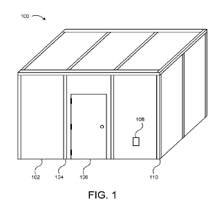
Figures 1 and 2 depict one embodiment of an enclosure 100 for
electromagnetic pulse ("EMP") shielding. Figure 1 depicts a perspective view
and
Figure 2 depicts a plan view with roof components removed so that wall
components
are visible.
[0022] EMPs may be produced by natural events such as solar flares or by
30 malicious
actors. For example, a high-altitude nuclear explosion may create a high-
altitude EMP ("HEMP"). In either case, a high-energy EMP may damage important
electrical and/or electronic equipment, such as power generation or switching
equipment, communications equipment, computer equipment, or the like. In
various
embodiments, an enclosure 100 for EMP shielding may be useful to protect such
CA 03170720 2022- 9-6
WO 2021/178726
PCT/US2021/020957
equipment inside the enclosure 100 from EMPs. Additionally, some EMPs are
human
created for non-malicious purposes such as physics research. An enclosure 100
may
be useful to separate EMP-producing equipment from EMP-sensitive equipment. In
further embodiments, an enclosure 100 for EMP shielding may also provide
effective
5 shielding from static magnetic fields, static electric fields,
electromagnetic waves such
as radio waves, microwaves, and X-rays, or the like.
[0023] In various embodiments, an enclosure 100 for EMP shielding may
include a plurality of sheets of EMP shielding material 102, disposed to
enclose a space.
In further embodiments, the enclosure 100 may include one or more EMP
shielding
10 connectors 104, 110 to bridge gaps between the sheets of EMP shielding
material 102.
EMP shielding material 102 and EMP shielding connectors 104, 110, in various
embodiments, may be capable of shielding equipment within the enclosure 100
from
electromagnetic pulses. Construction of the sheets of EMP shielding material
102 and
the EMP shielding connectors 104, 110 is described in further detail below
with
15 reference to subsequent Figures.
[0024] An enclosure 100, in some embodiments, may be a permanent (e.g.,
durable or long-lasting) building, such as a power substation. In some
embodiments,
an enclosure 100 may be a mobile or field-assembled building. For example, an
enclosure 100 may be a sensitive compartmented information facility (SCIF) to
shield
20 electronic data and communications equipment inside the SCIF from
harmful EMPs,
and to prevent detection from outside the SCIF of electromagnetic signals
generated
inside the SCIF. A portable SCIF may be an enclosure 100 on a truck or
trailer, or may
be a field-assembled building, where the sheets of EMP shielding material 102
and the
EMP shielding connectors 104, 110 are transported to a field location and
rapidly
25 assembled.
[0025] To form an enclosure 100, sheets of EMP shielding material 102 are
disposed to enclose a space. In the depicted embodiment, the space within the
enclosure
100 is fully enclosed by sheets of EMP shielding material 102 forming four
walls and
a roof (In some embodiments, a floor of an enclosure may also be formed by EMP-
30 shielding material.) A fully enclosed space may be accessed via a door
106, which may
be covered in EMP shielding material. One or more openings 108 may be provided
(e.g., in walls of a portable or field-assembled enclosure 100, in the floor
of a permanent
enclosure 100, or the like), to bring utilities such as electrical cables,
ventilation ducts,
CA 03170720 2022- 9-6
WO 2021/178726
PCT/US2021/020957
6
or the like, inside the enclosure. Such openings may be surrounded by smaller
panels
of EMP shielding material 102, in some embodiments.
[0026] In another embodiment, sheets of EMP shielding material 102 may be
disposed to partially surround or enclose a space, and the partially enclosed
space may
5 still be
referred to as being "enclosed" by the EMP shielding material 102, with the
resulting structure being referred to as an "enclosure." For example, in some
embodiments, three sheets of EMP shielding material 102 may be disposed to
form a
roughly C-shaped booth, with three walls and no roof, which may be sufficient
to
provide a desired level of shielding (e.g., between interference-producing
equipment
10 inside a
room where the booth is placed, and interference-sensitive equipment inside
the booth). Such a booth may still be referred to as an "enclosure" despite
not being
fully enclosed.
[0027] Sheets of EMP shielding material 102 may be substantially flat panels
of various sizes. For example, in an embodiment where an enclosure 100 is a
building,
15 sheets of
EMP shielding material 102 may be produced in sizes comparable to sheets
of drywall or oriented strand board (OSB) sheathing, such as in 4' by 8', 4'
by 10'
and/or 4' by 12' sizes. As another example, in an embodiment where an
enclosure 100
is for shielding a computer, sheets of EMP shielding material 102 may be
produced in
sizes comparable to comparable to the size of the front, top, and sides of a
computer
20 case. In
some embodiments, smaller sheets of EMP shielding material 102 may be cut
from larger sheets. Additionally, in some embodiments, EMP shielding material
102
may be molded or stamped to form three-dimensional structures rather than
sheets.
[0028] In some embodiments, an enclosure 100 may include support structure
other than the sheets of EMP shielding material 102. For example, vertical
sheets of
25 EMP
shielding material 102 for the walls of the enclosure 100 may be attached
(e.g.,
glued with construction adhesive) to support structure such as a concrete or
masonry
wall, wooden or metal studs, or the like. In some embodiments, however, sheets
of
EMP shielding material 102 may include an inner substrate and/or one or more
outer
substrates (as described below), which may provide sufficient rigidity so that
the sheets
30 of EMP
shielding material 102 are connectable by the EMP shielding connectors 104,
110 to form a free-standing enclosure 100, without attaching the sheets of EMP
shielding material 102 to another wall. EMP shielding material that includes
such a
substrate may be referred to as "structural" EMP shielding material 102. In
some
embodiments, sheets of structural EMP shielding material 102 may be useful for
CA 03170720 2022- 9-6
WO 2021/178726
PCT/US2021/020957
7
forming free-standing structures, but may be significantly heavier than sheets
of non-
structural EMP shielding material 102, which may be added to existing
structures
without adding the full weight of structural EMP shielding material 102.
[0029] When sheets of EMP shielding material 102 are disposed to enclose a
5 space,
gaps between sheets may allow for transmission rather than
attenuation/shielding
of EMPs and other electromagnetic waves. For example, gaps may exist between
the
edges of two adjacent sheets that are co-planar to each other in the same
wall, and corner
gaps may exist between sheets in adjacent walls. Thus, in various embodiments,
EMP
shielding connectors 104, 110, may be coupled to the sheets of EMP shielding
material
10 102, to
bridge (and shield) gaps between the sheets. In the depicted embodiment, flat
connectors 104 bridge gaps between co-planar sheets of EMP shielding material
102
(e.g., two sheets in the same wall, and angled connectors 110 bridge corner
gaps.
Referring to the plan view of Figure 2, the enclosure 100 in the depicted
embodiment
includes EMP shielding connectors 104, 110 to bridge gaps between sheets on
both the
15 interior
and the exterior. In another embodiment, an enclosure 100 may include EMP
shielding connectors 104, 110 on one side of the gaps between sheets of EMP
shielding
material 102, rather than on both sides of the gaps.
[0030] Construction of the sheets of EMP shielding material 102 and the EMP
shielding connectors 104, 110 is described in further detail below with
reference to
20 subsequent
Figures. Thicknesses of various materials and components are not depicted
to scale in the Figures, to more clearly show the relation of materials to
other materials
and components. For example, in Figure 2, the sheets of structural EMP
shielding
material 102 may be 4' wide, 8' tall, and approximately 5/8" to 3/4" thick,
but the
thickness of the sheets 102 is depicted as substantially larger, proportionate
to the width,
25 so that
the gaps between sheets 102 may more clearly be seen. Also, the EMP shielding
connectors 104, 110 may be thinner than the sheets of EMP shielding material
102 but
are depicted as thick lines so that they may be clearly seen in the plan view.
Similarly,
in Figures 3-9, layers of materials that form the sheets of EMP shielding
material and
EMP shielding connectors 104, 110 are depicted without attempting to
accurately
30 depict the
relative thicknesses of each layer, and even extremely thin layers may be
depicted with some greater thickness for greater ease in showing which layers
are
formed from which materials, and how the layers are arranged.
[0031] Figure 3 is a side view illustrating one embodiment of EMP shielding
material 300. The EMP shielding material 300 in the depicted embodiment, may
form
CA 03170720 2022- 9-6
WO 2021/178726
PCT/US2021/020957
8
a sheet of EMP shielding material 102 as described above with reference to
Figure 1.
In the depicted embodiment, the EMP shielding material 300 includes a first
set 308 of
alternating layers of ferrous metal 304 and non-ferrous metal 302, a second
set 310 of
alternating layers of ferrous metal 304 and non-ferrous metal 302, and an
electrically
5 non-
conductive layer 306 disposed between the first set 308 of alternating layers
and
the second set 310 of alternating layers.
[0032] Ferrous metal 304, in various embodiments, may refer to any
ferromagnetic metal. Ferrous metal 304 may be electrically conductive, and may
have
a magnetic permeability (y) substantially greater than the vacuum permeability
(110).
10 For
example, the relative permeability (u/kto) of ferrous metal 304 may be above
40, in
a range from 100 to several hundred, in a range from 1000 to several thousand,
or more.
Non-ferrous metal 302, in various embodiment, may be metal that is not
ferromagnetic.
Non-ferrous metal 302 may be electrically conductive and may have a relative
magnetic
permeability (p/Ato) of approximately 1.
15 [0033] A
"set- 308, 310 of alternating ferrous and non-ferrous layers, in various
embodiments, includes at least one layer of ferrous metal 304, and at least
one layer of
non-ferrous metal 302. Thus, in the depicted embodiment, each set 308, 310 of
alternating ferrous and non-ferrous layers includes one layer of ferrous metal
304, and
one layer of non-ferrous metal 302. In another embodiment, a set 308, 310 of
20
alternating ferrous and non-ferrous layers may include more than two layers,
alternating
between ferrous metal 304 and non-ferrous metal 302. For example, a set 308,
310 of
alternating ferrous and non-ferrous layers may include 4 layers, 6 layers, 8
layers, an
odd number of layers (e.g., with one more layer of ferrous metal 304 than of
non-ferrous
metal 302), or the like.
25 [0034] The
ferrous metal 304, in some embodiments, may be sheet steel, such
as cold rolled steel or galvanized sheet steel. Using galvanized steel may add
weight
but provide corrosion protection. In some embodiments, the ferrous metal 304
may be
18-gauge galvanized sheet steel, 20-gauge galvanized sheet steel, 22-gauge
galvanized
sheet steel, or other galvanized or ungalvanized sheet steel with a thickness
in a range
30 from 12-28
gauge. Use of thicker ferrous metal 304 may add weight but improve
effectiveness of the EMP shielding, while thinner ferrous metal 304 may
provide more
lightweight shielding with lower shielding effectiveness. Lower shielding
effectiveness
may be suitable for enclosures 100 where a high degree of shielding is not
needed, or
where some shielding is provided by other materials (e.g., by concrete walls).
CA 03170720 2022- 9-6
WO 2021/178726
PCT/US2021/020957
9
[0035] The non-ferrous metal 302, in some embodiments may be an electrically
conductive but nonferromagnetic metal such as aluminum or copper. In some
embodiments, the non-ferrous metal 302 may be aluminum sheet metal with a
thickness
in a range from 18-28 gauge. In some embodiments, the non-ferrous metal 302
may be
5 aluminum foil, copper foil, or the like.
[0036] In some embodiments, the ferrous metal 304 and/or the non-ferrous
metal 302 may be perforated metal, such as a metal mesh, a metal screen, sheet
metal
with slots or holes, or the like. The use of perforated metal may reduce the
weight of
the EMP shielding 300 compared to using non-perforated metal.
10 [0037] The
electrically non-conductive layer 306, in various embodiments, may
be any electrically non-conductive material such as wood, foam board,
fiberboard,
drywall, fiber-reinforced plastic, or the like. A solid material for the
electrically non-
conductive layer 306 may act as a spacer between the first and second sets
308, 310 of
alternating ferrous and non-ferrous layers, and/or as a substrate to support
the first and
15 second
sets 308, 310. An electrically non-conductive layer 306 or substrate disposed
between the first set 308 of alternating layers and the second set 310 of
alternating
layers may be referred to as an inner substrate. In some embodiments, an inner
substrate
and/or an outer substrate as described below may be or may include an aramid
fiber
material such as KEVLAR , to provide both ballistic and EMP protection.
20 [0038] In
another embodiment, however the electrically non-conductive layer
306 rnay be an air gap. For example, the first and second sets 308, 310 of
alternating
ferrous and non-ferrous layers may be coupled by small non-conductive spacer
blocks
or spacer pillars, or may be independently supported by two different
substrates, leaving
an air gap between the first and second sets 308, 310. In some embodiments,
thickness
25 of the
electrically non-conductive layer 306 may be in a range from approximately
1/8"
to approximately 1/2".
[0039] In certain embodiments, the first set 308 of alternating layers and the
second set 310 of alternating layers are both disposed with the ferrous metal
304 in
contact with the electrically non-conductive layer 306. In various
embodiments, sets
30 308 of
alternating ferrous and non-ferrous layers may include an odd number of layers
with outward-facing ferrous metal 304, an odd number of layers with outward-
facing
non-ferrous metal 302, or an even number of layers with ferrous metal 304 on
one face
and non-ferrous metal 302 on the opposite face. The applicant has discovered
by
experimentation that providing sets 308, 310 of alternating layers with the
ferrous metal
CA 03170720 2022- 9-6
WO 2021/178726
PCT/US2021/020957
304 exposed on at least one face, and positioning the sets 308, 310 of
alternating layers
with the ferrous metal 304 face disposed toward or in contact with the
electrically non-
conductive layer 306, provides better shielding than if a non-ferrous metal
302 face is
disposed toward or in contact with the electrically non-conductive layer 306.
However,
5 other
configurations with a non-ferrous metal 302 face in contact with the
electrically
non-conductive layer 306 may provide sufficiently effective shielding in some
embodiments.
[0040_1 To make a sheet of EMP shielding material 300, the layers of non-
ferrous metal 302, ferrous metal 304, and electrically non-conductive material
306 are
10 provided,
and bonded together so that the electrically non-conductive material 306 is
bonded between sets 308, 310 of alternating ferrous and non-ferrous layers, as
described above. Various adhesives will be recognized by a skilled person as
suitable
for bonding layers together. In some embodiments, to prevent corrosion and/or
delamination, edges of the first set 308 of alternating layers and the second
set 310 of
15
alternating layers (and/or of the resulting sheet of EMP shielding material
300) may be
sealed with epoxy or another waterproof material. In some embodiments, faces
of a
sheet of EMP shielding material 300 may also be weatherproofed or waterproofed
by
bonding a sheet of weatherproofed or waterproofed such as TYVEK barrier
material
to the outside of the EMP shielding material 300.
20 [0041] In
some embodiments, providing additional layers may improve the
shielding effectiveness and/or structural rigidity of the EMP shielding
material 300.
Various embodiments of EMP shielding material 300 with different or additional
layers
are described below with reference to subsequent figures.
[0042] Figure 4 is a side view illustrating another embodiment of EMP
25 shielding
material 400. The EMP shielding material 400 in the depicted embodiment,
may form a sheet of EMP shielding material 102 as described above with
reference to
Figure 1. In the depicted embodiment, the EMP shielding material 400 includes
first
and second sets 408, 410 of alternating layers of ferrous metal 404 and non-
ferrous
metal 402, and an electrically non-conductive layer 406, each of which may be
30 substantially as described above with reference to Figure 3.
[0043] Although the embodiment of EMP shielding material 300 depicted in
Figure 3, has one ferrous layer and one non-ferrous layer in each of the sets
308, 310
of alternating layers, some other embodiments of EMP shielding material may
include
similar sets of alternating layers, where at least one of the sets of
alternating layers
CA 03170720 2022- 9-6
WO 2021/178726
PCT/US2021/020957
11
comprises two ferrous layers and two non-ferrous layers. For example, in the
depicted
embodiment, the second set 410 of alternating layers includes two layers of
ferrous
metal 404, alternating with two layers of non-ferrous metal 402. In the
depicted
embodiment, the first set 408 of alternating layers includes one layer of
ferrous metal
5 404 and one layer of non-ferrous metal 402, as in Figure 3.
[0044] Figure 5 is a side view illustrating another embodiment of EMP
shielding material 500. The EMP shielding material 500 in the depicted
embodiment,
may form a sheet of EMP shielding material 102 as described above with
reference to
Figure 1. In the depicted embodiment, the EMP shielding material 500 includes
first
10 and second sets 508, 510 of alternating layers of ferrous metal 504 and
non-ferrous
metal 502, and an electrically non-conductive layer 506, each of which may be
substantially as described above with reference to Figures 3 and 4.
[0045] Although the embodiment of EMP shielding material 400 depicted in
Figure 4 has two layers of ferrous metal 404 alternating with two layers of
non-ferrous
15 metal 402 in only the second set 410 of alternating layers, some other
embodiments of
EMP shielding material may include similar sets of alternating layers, where
both the
first set of alternating layers and the second set of alternating layers
include two ferrous
layers and two non-ferrous layers. For example, in the depicted embodiment,
the first
and second sets 508, 510 both include two layers of ferrous metal 504,
alternating with
20 two layers of non-ferrous metal 502.
[0046] Figure 6 is a side view illustrating another embodiment of EMP
shielding material 600. The EMP shielding material 600 in the depicted
embodiment,
may form a sheet of EMP shielding material 102 as described above with
reference to
Figure 1. In the depicted embodiment, the EMP shielding material 600 includes
first
25 and second sets 608, 610 of alternating layers of ferrous metal 604 and
non-ferrous
metal 602, and an electrically non-conductive layer 606, each of which may be
substantially as described above with reference to Figures 3 through 5.
Additionally,
in the depicted embodiment, the EMP shielding material 600 includes an outer
substrate
612.
30 [0047] An
outer substrate 612, in various embodiments, may be a material
bonded to the outside of the EMP shielding material 600, to provide rigidity
or increase
rigidity of the EMP shielding material 600. In some embodiments, EMP shielding
material 600 with an inner substrate for the electrically non-conductive layer
606 and
an outer substrate 612 may be more rigid than other embodiments of EMP
shielding
CA 03170720 2022- 9-6
WO 2021/178726
PCT/US2021/020957
12
material, and more suitable for use as structural EMP shielding material. In
some
embodiments, the outer substrate 612 may be an electrically non-conductive
material,
such as wood, OSB, fiberboard, structural insulated sheathing (e.g.,
structural insulation
available from OX Engineered Products, LLC, of Pennsylvania), or the like.
Although
5 Figure 6
depicts an outer substrate on one side of the EMP shielding material 600, some
embodiments may include outer substrates on both sides of the EMP shielding
material
600. Thus, outer substrate(s) 612 may be bonded to one or both sets 608, 610
of
alternating layers.
[0048] Figure 7 is a side view illustrating another embodiment of EMP
10 shielding
material 700. The EMP shielding material 700 in the depicted embodiment,
may form a sheet of EMP shielding material 102 as described above with
reference to
Figure 1. In the depicted embodiment, the EMP shielding material 700 includes
first
and second sets 708, 710 of alternating layers of ferrous metal 704 and non-
ferrous
metal 702, an electrically non-conductive layer 706, and two outer substrates
712, each
15 of which
may be substantially as described above with reference to Figures 3 through
6.
[0049] In the depicted embodiment, the electrically non-conductive layer 706
is an air gap. Additionally, in this embodiment, an outer substrate 712 is
bonded to the
first set 708 of alternating layers, and another outer substrate 712 is bonded
to the
20 second set
710 of alternating layers. Thus, each set 708, 710 of alternating layers is
supported by its own outer substrate 712. In some embodiments, half-panels
that
include one of alternating layers and one substrate (e.g., the top half of
Figure 7 and the
bottom half of Figure 7) may be transported separately and assembled on
opposite sides
of an air gap, with spacers used to maintain the distance between half-panels.
25 [0050]
Figures 8 and 9 illustrate two embodiments of EMP shielding connector
800, 900. The EMP shielding connector 800 depicted in Figure 8 is a flat
connector
104 as described above with reference to Figure 1, to bridge a gap between co-
planar
sheets of structural EMP shielding material 102. The EMP shielding connector
900
depicted in Figure 9 is an angled connector 110 as described above with
reference to
30 Figure 1,
to bridge a corner gap between sheets of structural EMP shielding material
102. In the depicted embodiments, EMP shielding connectors 800, 900 each
include at
least one layer of ferrous metal 804, 904, at least one layer of non-ferrous
metal 802,
902, and a bonding material 814, 914 for bonding to sheets of structural EMP
shielding
material.
CA 03170720 2022- 9-6
WO 2021/178726
PCT/US2021/020957
13
[0051] The ferrous metal 804, 904 and non-ferrous metal 802, 902 may be
substantially as described above for sheets of EMP shielding material. In some
embodiments, ferrous metal 904 for an angled connector 900 may be a galvanized
steel
corner bead for drywall corners. The bonding material 814, 914 may be vinyl
strip
5 adhesive, double-sided acrylic adhesive, pressure-sensitive adhesive, or
the like. In the
depicted embodiment, the flat connector 800 is reversable for use on either
side of a
gap between co-planar sheets of structural EMP shielding material, and the
angled
connector 900 includes adhesive on the concave side of the angle, for use on
an exterior
corner. In another embodiment, an angled connector 900 may have layers
reversed,
10 with adhesive on the convex side of the angle, for use on an interior
corner.
[0052] The present invention may be embodied in other specific forms without
departing from its spirit or essential characteristics. The described
embodiments are to
be considered in all respects only as illustrative and not restrictive. The
scope of the
invention is, therefore, indicated by the appended claims rather than by the
foregoing
15 description. All changes which come within the meaning and range of
equivalency of
the claims are to be embraced within their scope.
CA 03170720 2022- 9-6