Note: Descriptions are shown in the official language in which they were submitted.
WO 2021/179046
PCT/AU2021/050214
Peristaltic pump
Field of the invention
[0001] The present invention relates to a peristaltic pump, in
particular a multiplex
planar peristaltic pump. The invention also concerns a rotor and a stator for
such a
pump.
Background of the invention
[0002] A peristaltic pump (also sometimes referred to as a roller
pump) is a type of
positive displacement pump used for pumping fluids, the fluid contained within
a flexible
tube mounted in a pump casing or stator.
[0003] In a typical peristaltic pump, a rotor carries a number of
circumferential rollers
mounted on bearings, each of which is arranged to compress the flexible tube.
As the
rotor rotates, a part of the tube is compressed by a roller, thus occluding
the tube and
forcing the fluid to move through the tube in the direction of movement of the
roller. The
tube is fabricated from a resilient material and thus reassumes its normal
calibre after
the compression by the roller ceases. This process of peristalsis mimics many
biological
systems (such as the action of oesophagus or the gastrointestinal tract). A
body of fluid
(or bolus) trapped between two successive rollers is thus transported at
ambient
pressure toward the pump outlet.
[0004] Typically, peristaltic pumps are employed in the pumping
of clean or sterile
fluids, as there is no contact between the pump mechanism and the content of
the tube.
Such pumps are often used in medical applications, such as to pump IV fluids
through
infusion devices, in haemodialysis systems, or in heart-lung machines to
circulate blood
during bypass surgery. Peristaltic pumps are also used to pump aggressive
fluids and
chemicals, including very viscous fluids and high solids slurries, where
isolation of the
material from the environment is important.
[0005] Peristaltic pumps may run continuously, or they may be
indexed through
partial revolutions to deliver smaller amounts of fluid. Aside from the
benefits mentioned
above, peristaltic pumps offer the advantages of low maintenance, few moving
parts,
prevention of backflow and siphon, and accurate dosing (as a fixed amount of
fluid is
1
CA 03171076 2022- 9-8
WO 2021/179046
PCT/AU2021/050214
pumped per rotation of the rotor). This latter characteristic (the ability to
provide a flow
rate directly proportional to the driving peristaltic motion) means that the
pump can
faithfully produce a predefined flow rate without the need for feedback-
control by costly
flow sensors. Further, as an in-line pump, a peristaltic pump affords the
ability to change
fluid medium without disrupting flow (unlike pressure driven pumping solutions
such as
syringe systems or pneumatic pumps). This means that various operations can be
performed on the content of a receiving reservoir in real time, e.g. medium
top-up, drug
addition, gas equilibration, etc.
[0006] Peristaltic pumps have also been adopted in biological and
biochemical
analytical workflows for various purposes including transferring of fluids,
washing and
perfusion. One key application of peristaltic pump is in in-vitro perfusion of
biological
samples.
[0007] A number of commercial peristaltic pumps are available on
the market. The
target flow rate range is usually in the range of (at the minimum) mL/min,
primarily
useful in tissue-scale/organ-scale continuous perfusion or transient
flushing/rinsing of
smaller samples. Such pumps use flexible tubing as the fluid carrier, which
tends to
degrade with time due to abrasion.
[0008] An alternative to the conventional circumferential roller
peristaltic pump is the
planar peristaltic pump. This takes the form of a thrust ball bearing
assembly, consisting
of a rotor disc carrying a ring of stainless steel balls, as illustrated in
Figure 1. The rotor
1 is rotated at a particular angular velocity, and the balls are carried in a
planar cage
disc 3 which provides the required support and spacing. A soft substrate
surface layer 2
on rotor 1 provides the friction required to rotate the balls 4, which are
arranged to
compress and roll on a silicon rubber substrate in which a fluid channel 6 is
embedded.
Stationary support disc or stator 7 underlies fluid channel 6 and substrate 5.
The
separation between rotor 1 and stator 7 is arranged such that the compression
force
exerted by balls 4 occludes fluid channel 6. As roller 1 rotates, all of the
balls 4 are
rolled in unison, resulting in the fluid trapped in the channel between two
adjacent balls
4 being pushed forward. As will be understood, if the velocity of rotor 1 is
v, cage disc 3
rotates at v/2, and the only sliding friction in the mechanism is that
sustained between
balls 4 and cage disc 3.
2
CA 03171076 2022- 9-8
WO 2021/179046
PCT/AU2021/050214
[0009] Examples of concepts around the planar peristaltic pump
include the
disclosure of US patent application no. 2014/0356849 (Vanderbilt University),
US patent
application no. 2018/0058438 (Novartis AG), US patent application no.
2018/0209552
(Vanderbilt University), European patent application no. 1,662,142 (Debiotech
S.A.), US
patent application no. 2018/0149152 (Takasago Electric, Inc) and international
patent
publication WO 2012/048261 (Vanderbilt University).
[0010] Planar peristaltic pumps allow smaller flows to be
accommodated, and recent
developments in this field include the 'on-chip pump', referring to a rotary
planar
peristaltic micropump fabricated in an elastomeric material such as
polydimethylsiloxane (PDMS) by soft lithography, suitable for microfluidic
integration. In
such a microfluidic device the tubing is a microchannel embedded into or
beneath a
planar membrane. Such devices can provide a very consistent, continuous,
controllable
flow rate at the nL-pUmin scale.
[0011] With perfusion of biological samples, parallel flow of
multiple samples is
generally required. While multiple pumps can be used for this, developments in
multiplexing have included stacking peristaltic pumps into a single assembly,
providing
multiple independent channels each operated by rotation of a rotor turned by a
common
shaft or by concentric shafts. Examples include the disclosures of US patent
no.
9,504,784 (Cole-Parmer Instrument Company LLC) and US patent application no.
2009/0035165 (Agilent Technologies Inc.).
[0012] Despite these advances, multiplexing capacity remains very
limited, creating
operational limitations particularly in clinical and laboratory environments.
[0013] Reference to any prior art in the specification is not an
acknowledgment or
suggestion that this prior art forms part of the common general knowledge in
any
jurisdiction or that this prior art could reasonably be expected to be
understood,
regarded as relevant, and/or combined with other pieces of prior art by a
skilled person
in the art.
Summary of the invention
[0014] In one aspect, the invention provides a rotor for a
peristaltic pump, the rotor
comprising a body for rotation about an axis, the body having a first side and
a second
3
CA 03171076 2022- 9-8
WO 2021/179046
PCT/AU2021/050214
side, the body supporting a plurality of spaced first rollers extending from
the body on
the first side, the first rollers positioned at a first common radius from the
axis, the body
further supporting a plurality of spaced second rollers extending from the
body on the
second side, the second rollers positioned at a second common radius from the
axis.
[0015] When used in a peristaltic pump, the first and second
rollers are thus able to
apply force substantially in the axial direction (ie. in a direction normal to
first and
second sides of the rotor body) simultaneously onto adjacent surfaces
positioned on
both sides of the body, thus increasing the pumping capacity of a single
rotor.
[0016] Preferably, the first rollers are arranged to contact the
second rollers within the
body.
[0017] In a preferred form, the spacing between the plurality of
first rollers is
substantially the same as that between the plurality of second rollers, the
first common
radius is substantially equal to the second common radius, the position of the
plurality of
first rollers is phase shifted with respect to that of the plurality of second
rollers, each of
the plurality of first rollers is arranged to contact two of the plurality of
second rollers,
and each of the plurality of second rollers is arranged to contact two of the
plurality of
first rollers.
[0018] With this arrangement, when used in a peristaltic pump,
the first rollers and the
second rollers roll against one another, with forces in the axial direction
carried by the
rolling contact of the surfaces of the rollers against each other, rather than
by sliding
contact between the rollers and the rotor body.
[0019] The rotor body may have a generally planar form and be provided with
recesses in the first and second side to receive the first and second rollers
respectively,
the recesses meeting within the body to allow contact between the first and
second
rollers.
[0020] Alternatively, the body may comprise two planar parts, a
first rotor part
providing the first side of the rotor and a second rotor part providing the
second side of
the rotor, the first and second rotor parts being mutually engageable to
retain the first
and the second rollers between them, each of the first and second rotor parts
having a
4
CA 03171076 2022- 9-8
WO 2021/179046
PCT/AU2021/050214
plurality of apertures sized to allow the first and second rollers to extend
therethrough
while remaining captive between the first and the second roller parts, wherein
the
engagement between the first and the second roller parts provides that the
plurality of
apertures in the first roller part is out of phase with the plurality of
apertures in the
second roller part.
[0021] In one form, the rotor includes a further plurality of
spaced first rollers
extending from the body on the first side, the further plurality of spaced
first rollers
positioned at a third common radius from the axis different from said first
common
radius, additionally including a further plurality of spaced second rollers
extending from
the body on the second side, the further plurality of spaced second rollers
positioned at
a fourth common radius from the axis different from said second common radius.
[0022] In this way, the rollers may be arranged in multiple
concentric rings, allowing
peristaltic pumping in multiple fluid channels disposed in a similar
concentric
arrangement.
[0023] Preferably, the spacing between the further plurality of
first rollers is
substantially the same as that between the further plurality of second
rollers, the third
common radius is substantially equal to the fourth common radius, the position
of the
further plurality of first rollers is phase shifted with respect to that of
the further plurality
of second rollers, each of the further plurality of first rollers is arranged
to contact two of
the further plurality of second rollers, and each of the further plurality of
second rollers is
arranged to contact two of the further plurality of first rollers.
[0024] In accordance with this feature, the multiple concentric
rings of rollers on one
side of the rotor body are repeated on the other side, the rotor thus carrying
multiple
sets of mutually opposed offset rings of spaced rollers. This affords a very
low wear
arrangement, with a high multiplexing capacity.
[0025] In a further aspect, the invention provides a peristaltic
pumping unit comprising
the above-defined rotor assembled with a first stator and a second stator, the
first stator
having one or more compressible fluid channels arranged to be compressed by
said
first rollers and the second stator having one or more compressible fluid
channels
arranged to be compressed by said second rollers.
CA 03171076 2022- 9-8
WO 2021/179046
PCT/AU2021/050214
[0026] Preferably, the rotor body has a generally planar form and
the first and second
stators each has a planar surface on or in which the one or more compressible
fluid
channels are provided, wherein the rotor body is sandwiched between the first
and
second stators. Preferably this is done in a way to provide substantially the
same
compression on the one or more fluid channels of the first stator as that on
the one or
more fluid channels of the second stator.
[0027] In a preferred form, the pumping unit includes an adjuster
mechanism to tune
the separation between the first and second stators in order to adjust the
compression
on the one or more fluid channels.
[0028] Such adjustment allows the fluid channels to be occluded
by the rollers of the
rotor to the extent required to ensure desired pumping performance.
[0029] The first stator may include multiple fluid channels, each
of which includes an
arcuate portion at or substantially at said first common radius from the axis.
[0030] This allows the spaced first rollers to act on more than
one fluid channel.
[0031] Preferably, the arcuate portion is of a length greater
than the spacing between
the spaced first rollers, such that the arcuate portion is simultaneously
compressed by
at least two rollers of said plurality of first rollers.
[0032] This feature enhances the pumping function, both in terms
of uniformity of flow
and in terms of robustness and tolerance.
[0033] In one form, the first stator may be at least partly
formed by a compressible
material forming a substantially planar surface and compressible arcuate
portions of
multiple fluid channels at different radii, each fluid channel arranged to be
compressed
by a different plurality of rollers to drive flow in that fluid channel, the
stator including
one or more recesses in the compressible material shaped and positioned to
relieve
compression of a particular fluid channel by passage of rollers not in the
plurality of
rollers arranged to drive fluid flow in that particular fluid channel.
6
CA 03171076 2022- 9-8
WO 2021/179046
PCT/AU2021/050214
[0034] In a further aspect, the invention provides a peristaltic
pumping assembly,
comprising a plurality of the above-defined peristaltic pumping units, stacked
to align the
axis of each rotor, including a drive shaft configured to engage and rotate
each rotor.
[0035] Hence a common shaft can be used to drive a plurality of
similar pumping
units, multiplying the pumping capacity significantly.
[0036] In a further aspect, the invention provides a stator for a
peristaltic pump,
having a body with a planar surface and two or more fluid channels, each fluid
channel
having a compressible arcuate portion on or in the planar surface of the
stator, the
arcuate portions arranged to be compressed by a plurality of rollers mounted
on a rotor,
one or each of the arcuate portions connecting to further portions of the
fluid channel
extending in a direction away from the planar surface such that one or more of
the fluid
channels take a three dimensional path within the body of the stator.
[0037] In accordance with this aspect, one or each fluid channel
follows a three
dimensional path within the stator body, different parts of a single channel
disposed in
different axial planes (ie. at different depths below the planar surface).
This allows a
wide variety of different configurations of fluid channels to be used,
including concentric
fluid channel arrangements, while avoiding interference between channels. Flow
paths
can effectively interweave and overlap by use of the different planes,
allowing great
flexibility in regard to fluid channel configuration and positioning of inlet
and outlet ports
for the channels.
[0038] In one form, the body comprises two layers, namely a
surface layer made of a
compressible material and formed to provide said planar surface and said
compressible
arcuate portions of the two or more fluid channels and an underlying support
layer
bonded to said surface layer, the support layer made of a relatively
incompressible
material in which said further portions of the fluid channels are provided.
[0039] The compressible arcuate portions of the two or more fluid channels may
be
made by a process of soft lithography applied to the surface layer.
[0040] In one form, said further portions of the two or more
fluid channels each
connect to an inlet or exit portion of the fluid channel, the inlet or exit
portion extending
7
CA 03171076 2022- 9-8
WO 2021/179046
PCT/AU2021/050214
in a radial direction, wherein the body comprises a third layer underlying and
bonded to
said support layer, said third layer formed to provide said inlet or exit
portions.
[0041] The inlet or exit portion of each of the two or more fluid channels may
be made
by a suitable machining process applied to the third layer. This could be (for
example) a
process of soft lithography (suitable if the third layer is a compressible
elastomeric
material) or micro-milling (suitable if the third layer is a more rigid
material).
[0042] In one form, two of said two or more fluid channels are
parallel channels which
connect together to provide a common channel inflow and a common channel
outflow,
the compressible arcuate portions of said two parallel channels arranged to be
compressed by the rollers of said plurality of rollers in an out-of-phase
timing, in order to
reduce the pulsatile nature of the common channel outflow.
[0043] Preferably, the compressible arcuate portions of the two
parallel channels
have a substantially common radius, such that they can be compressed by a
plurality of
spaced rollers positioned at a common radius from an axis of rotation of said
rotor.
[0044] In one form of the stator, a first and a second arcuate
portion of, respectively,
a first and second of said two or more of the fluid compressible fluid
channels are at
different radii on the stator, the first arcuate portion arranged to be
compressed by a first
plurality of rollers to drive flow in said first fluid channel, the second
arcuate portion
arranged to be compressed by a second plurality of rollers to drive flow in
said second
fluid channel, the stator body including one or more recesses interrupting the
planar
surface, shaped and positioned to relieve compression of the first fluid
channel by
passage of the plurality of rollers which are arranged to drive fluid flow in
the second
fluid channel.
[0045] In a further aspect, the invention provides a peristaltic
pumping unit comprising
the above-defined stator assembled with a rotor, the rotor supporting or
driving a
plurality of rollers, the rollers positioned to compress the arcuate portions
of said two or
more compressible fluid channels.
[0046] The present invention therefore provides a rotary planar
multiplexed
microfluidic pump. Using a single control motor, the invention allows
multiplexing the
8
CA 03171076 2022- 9-8
WO 2021/179046
PCT/AU2021/050214
pumping capability for a large number of separate parallel lines. This has
particular
application in a continuous perfusion setup for multiple biological samples,
such as
culturing media.
Brief description of the drawings
[0047] Further aspects and advantages of the present invention
and further
embodiments of the aspects described in the preceding paragraphs will become
apparent from the following description, given by way of example and with
reference to
the accompanying drawings.
[0048] Figure 1 diagrammatically illustrates in side view a
planar peristaltic pump
according to the prior art;
[0049] Figure 2 shows in perspective view a dual ring roller ball
rotor in accordance
with the present invention, depicted in partial cutaway view to illustrate the
roller balls
contained in their respective rotor recesses;
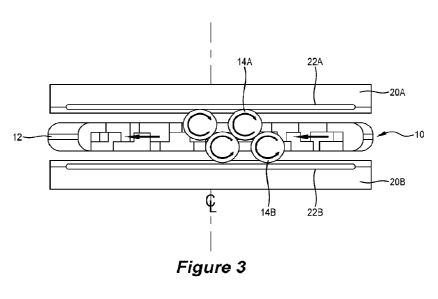
[0050] Figure 3 shows in side view the rotor of Figure 2 in a
pumping unit including
upper and lower fluid channel stator discs;
[0051] Figure 4 shows in plan view detail of the pumpting unit of
Figure 3;
[0052] Figures 5 and 6 show in perspective view two alternative
constructions of a
rotor in accordance with the present invention;
[0053] Figure 7 (exploded) and 7a illustrate a pumping assembly
comprising a stack
of the pumping units of Figure 3;
[0054] Figure 8 illustrates variants of fluid channel stator
discs;
[0055] Figures 9 and 10 illustrate different configurations of
fluid channel systems
embedded within fluid channel stator discs;
[0056] Figures 11 and 12 illustrate a further configuration of a
fluid channel system
embedded within a channel stator disc, including a resulting output flow
pattern;
9
CA 03171076 2022- 9-8
WO 2021/179046
PCT/AU2021/050214
[0057] Figure 13a depicts a variant of a channel stator disc to
address flow
disparities, with Figures 13b and 13c illustrating resulting flow
characteristics.
Detailed description of the embodiments
[0058] The dual ring roller ball rotor 10 of Figure 2 provides a
multiplex pump driver.
A planar rotor disc 12 with a central hex rotational drive shaft aperture 13
includes a
succession of shaped recesses on both sides as shown, arranged to hold an
upper ring
of evenly spaced roller balls 14A and a lower ring of evenly spaced identical
roller balls
14B. Both rings of balls 14A and 14B are at the same radius from the axial
centreline,
and sized and mounted to project a prescribed distance above and below,
respectively,
from the upper and lower faces of the disc 12.
[0059] As Figure 3 illustrates more clearly, the positioning of
the succession of roller
balls 14A is phase shifted with respect to that of roller balls 14B, with each
ball 14A
mounted to contact two successive balls 14B (and vice versa). This is achieved
by
arranging the upper ring of recesses with an angular offset from the lower
ring (so that
the angular position of each ball 14A is intermediate of that of two
successive balls
14B), with the recesses intersecting to allow the roller balls from the two
different sides
be in contact with each other.
[0060] Figure 3 also shows two channel stator discs arranged
parallel to rotor 10,
namely an upper channel stator disc 20A and a lower channel stator disc 20B.
Embedded within the resilient surfaces of stator discs 20A and 20B are upper
fluid
channel 22A and lower fluid channel 22B respectively, each fluid channel
positioned
close to the face of the channel stator disc which is adjacent rotor disc 12.
Further detail
regarding the embedded fluid channels 22A and 22B is provided below.
[0061] Channel stator discs 20A and 20B are arranged such that
the resilient
surfaces of, respectively, their lower and upper faces are compressed by balls
14A and
14B, so to occlude fluid channels 22A and 22B.
[0062] The operation of the pumping unit (provided by rotor 10 sandwiched
between
the stator discs 20A and 20B), is as follows. When rotor 10 is rotated in a
clockwise
direction (when viewed from above in Figure 3), due to the high friction
surface of stator
CA 03171076 2022- 9-8
WO 2021/179046
PCT/AU2021/050214
disc 20A roller balls 14A rotate in a clockwise direction, while roller balls
14B rotate in
an anticlockwise direction. Hence, where they are contiguous, roller balls 14A
and 14B
rotate in opposite directions at the same speed, resulting in them rolling
against one
another with no sliding friction. The only sliding friction in the mechanism
is at the points
where balls 14A, 14B contact the surfaces of the recesses in rotor disc 12,
and since
the forces on the roller balls are only in the axially aligned direction (and
thus carried by
other roller balls), this sliding friction (and therefore the wear) is
minimal.
[0063] The rolling compression of the surfaces of channel stator discs 20A and
208
results in peristaltic occlusion of both fluid channels 22A and 22B, providing
parallel fluid
flow from a single pump drive.
[0064] As Figure 4 illustrates, to further boost the multiplexing
capability of the
pumping unit, multiple fluid channels (in this example, four) are provided in
each
channel stator disc 20A, 20B, increasing to eight the number of fluid channels
operated
by a single rotor 10. More fluid channels can be used (minimising channel
length to
accommodate the maximum number of fluid channels on each stator channel stator
disc). Although not essential, ideally there should always be more than two
balls fully
occluding each fluid channel at any point of time, in order to provide an
adequate
channel sealing for the most effective pumping at ambient pressure.
[0065] For illustration purposes, Figure 4 shows in plan view
upper channel stator
disc 20A bearing on rotor 10. At least a part of each fluid channel takes a
substantially
arcuate course, arranged and positioned in such a way that it can be fully
occluded by
at least two roller balls 14A. Fluid channel 22A connects an inlet port 22Ain
to an outlet
port 22Ain, positioned towards the periphery of channel stator disc 20A as
shown.
Diametrically opposed to fluid channel 22A is a similar fluid channel 22A'
connecting an
inlet port 22A'IN to an outlet port 22K0ut. Intermediate these two fluid
channels and
mutually diametrically opposed are fluid channels 24A and 24A', which are
identical but
(in this example) of twice the cross sectional area (bore) of fluid channels
22A, 22A'.
[0066] As rotor 10 rotates in the clockwise direction, fluid
entering at ports 22Ain, etc.
is peristaltically pumped by roller balls 14A along the fluid channels to exit
at outlet ports
22A0ut, etc. While the flow in fluid channel 22A is equal to that in fluid
channel 22A',
twice that flow is pumped through fluid channels 24A and 24A'. As will be
understood,
11
CA 03171076 2022- 9-8
WO 2021/179046
PCT/AU2021/050214
the 2:1 bore ratio of fluid channels 24A/24A' to 22A/22A' is merely
illustrative. The bore
of each fluid channel can of course be selected to provide the desired fluid
flow in that
channel at a given RPM of rotor 10.
[0067] Each channel stator disc 20A, 20B is constructed of two
layers of PDMS
material, the fine fluid channels 22A etc. formed by soft lithography (as
generally known
and as discussed above). Such a microchannel has a cross sectional form that
is
approximately rectangular and is formed in the surface of one or both of the
layers of
PDMS material, those surfaces bonded together to encapsulate the channel. The
face
layer of PDMS is a relatively thin membrane layer, to afford ready compression
by the
roller balls, while the base layer is a thicker substrate layer. As will be
understood, the
base layer may be fabricated from a less resilient material (eg. a synthetic
resin such as
polymethyl methacrylate, PMMA).
[0068] It will be understood that other geometries and
fabrication techniques are
equally possible. For example, rather than a rectangular section a
microchannel may
have a circular segment cross section, for example with the same or a similar
radius to
that of roller balls 14A, 14B. This form may be achieved by micro-machining a
groove of
semicircular section of the required diameter in a more resilient base layer
(such as a
PMMA base layer), the flexible PDMS face layer forming a planar overlay
closing the
groove to form the channel. When a roller ball compresses the microchannel it
pushes
the elastomeric membrane into the arcuate groove following its curvature, to
occlude
the channel. Further, it is not necessary to form the microchannels from the
bonding of
two separate elements. They may instead be machined into a material using a
suitable
microfabrication technique, such as casting, moulding, laser machining, 3D
printing
techniques, etc.
[0069] Figures 5 and 6 illustrate two alternative constructions
of rotor 10. The
construction in Figure 5 is in many ways similar to that of Figure 2,
comprising a single
rotor disc 12 with the roller balls meeting due to the interconnection of the
succession of
retaining recesses from each side of the disc. In this way, rotor disc 12 acts
as a dual
ring ball bearing cage. Roller balls 14A, 14B may be retained in their
recesses solely by
the compressive action of the respective surfaces of channel stator discs 20A
and 20B
(such that individual roller balls can be readily removed and replaced as
required, eg. as
12
CA 03171076 2022- 9-8
WO 2021/179046
PCT/AU2021/050214
a result of wear or rust), or the construction and sizing may be of a diameter
that each
roller ball can 'pop fit' into the interior of the recess. For example, rotor
disc 12 may be
made from a slightly pliable metal material, the balls able to 'pop fit' into
the receiving
recesses immediately after subjecting rotor disc 12 to heat expansion (similar
to the
processes used in ball bearing race assembly fabrication).
[0070] As can be seen from the cutaway part of the rotor 10 of Figure 5, this
construction comprises two generally disc shaped halves 12' and 12", each
including a
ring of shaped apertures to accommodate roller balls 14A, 14B, the halves 12'
and 12"
brought together and joined to define a central annular-shaped cavity in which
roller
balls 14A contact roller balls 14B. Additional elements 16 are included to
connect (or
reinforce the connection between) rotor halves 12' and 12", to maintain a
uniform
separation between their planar outer faces (and ensure the required
separation
between the centres of roller balls 14A and 14B). As the skilled reader will
understand,
such a two-part construction is not essential, and alternative fabrication
methods may
be used to produce such a structure.
[0071] The construction of Figure 6 comprises an upper rotor disc part 12A and
a
lower rotor disc part 12B, united by a central boss portion (not fully
visible) around drive
shaft aperture 13. The interconnection is achieved in a manner that disposes
the
recesses in upper rotor disc part 12A to alternate in position with those of
lower rotor
disc part 12B. The roller balls 14A, 14B have a diameter larger than that of
the
recesses, and are placed in the recesses before parts 12A and 12B are united
so that
they are then held in place, rotor 10 becoming a single-piece component once
assembly
is complete
[0072] As shown in Figures 7 and 7a, multiples of the pumping unit described
above
are stacked to provide a multiplex pumping assembly 30, all driven by a single
rotary
hex shaft 42 sized to engage with the hex apertures 13 in rotor discs 12. In
this example
six pumping units (12 channel stator discs) are combined, boosting the
multiplexing
capability to 48 fluid channels in total.
[0073] As will be understood, hex shaft 42 engaging with hex apertures 13 is
only one
example way of applying rotational drive to rotor discs 12, and any suitable
shaping or
engagement can be used. Rotor disc 12 should preferably be able to move freely
in the
13
CA 03171076 2022- 9-8
WO 2021/179046
PCT/AU2021/050214
axial direction, so that the compressive force of roller balls 14A and 14B
normal to the
plane of rotor disc 12 (ie. in the axial direction) is distributed (and
therefore applied
evenly) between channel stator discs 20A and 20B.
[0074] Assembly 30 includes a closure plate part 34, a base
support plate part 36,
and five intermediate support plate parts 38, each of which parts 38 separates
two
pumping units. Plate parts 34, 36 and 38 each provide a planar support for
respective
channel stator discs 20A, 20B, Plate parts 34, 36 and 38 all have four corner
stanchions
39 to mutually register all of the pumping units in angular orientation, each
of corner
stanchions 39 having an axially aligned aperture therethrough, allowing all
the parts to
be mechanically clamped together by means of screw rods 40 and end nuts (not
shown).
[0075] As shown in Figure 7, each intermediate support plate 38 has a central
aperture of diameter larger than that of shaft 42. If desired, this aperture
may be
reduced and configured to provide a plurality of ring bearings for shaft 42,
to maintain
shaft 42 on the axial centreline (with shaft 42 redesigned to have a circular
section, at
least at the axial positions of the intermediate support plates 38).
Alternatively or
additionally, the circumference of rotors 12 may be increased to bear against
the
arcuate shaped inner surfaces of corner stanchions 39, so assisting in
maintaining shaft
42 on the axial centreline and assisting the dynamic stability of the
assembly.
[0076] In a prototype designed, built and tested by the
inventors, rotor 10 comprised
two rings of 18 evenly spaced stainless steel ball bearings each 5 mm in
diameter
mounted in recesses 3.2 mm in depth and 5.2 mm in diameter. Rotor disc 12 was
55
mm in diameter and 4.8 mm in thickness, with the roller ball rings mounted to
follow a
circular path 40 mm in diameter.
[0077] Ideally, rotor disc 12 is made from a material such as
acetal resin. Such a
material is low weight and fatigue resistant, displays low friction and wear,
has high
stiffness, strength and hardness and very good dimensional stability. Roller
balls 14A,
14B are made from a suitable rigid material that rolls with minimum friction,
such as
stainless steel or a suitable glass or ceramic material.
14
CA 03171076 2022- 9-8
WO 2021/179046
PCT/AU2021/050214
[0078] The axial separation between channel stator discs 20A and 20B in each
pump
unit may be adjusted to provide a prescribed degree of compression on the
stator disc
by the roller balls, in order to fully occlude the fluid channel within. In
the prototype
tested, a compression of 750 pm in depth was generated, which was found to
ensure
effective occlusion of fluid channels of 80 pm in height and 500 and 800 pm in
width
(channel bore 0.04 and 0.064 mm2, respectively). The fluid channels were
formed in the
surface of a PDMS base layer of 2.7 mm thickness, the channels then closed by
oxygen
plasma bonding of a 500 pm thick PDMS face layer to the PDMS base layer.
[0079] The dimensions provided in Figure 7a show the height and width of the
prototype six-stage multiplex pump assembly. This can be mounted to an OEM
device
arranged to drive the head of shaft 42, or alternatively engaged with a custom
motor
driver.
[0080] For yet a further increase in multiplexing capacity, the
number of rings of roller
balls 14A, 14B may be increased. This modification is illustrated in Figure 8c
(compare
Figure 8a), which shows four concentric rings of roller balls 114A on the
upper side of
rotor 110 (the arrangement replicated on the lower side).
[0081] Such an arrangement necessitates a revised design of the
channel stator
discs as shown in Figure 8d (compare Figure 8b), in which lower channel stator
disc
120B is provided with multiple fluid channels (122B, etc.) at four different
radii,
corresponding to the radii of the four rings of roller balls 114B. As will be
understood,
the flow rates across the concentric peristaltic channels must be calibrated,
as they
experience peristaltic motions of different speeds. If equal flow rates are
required,
suitable selection of fluid channel bores is necessary.
[0082] In this example a total of 11 channels are shown; using
this design of stator
disc in a six-stage multiplex pumping assembly 30 of the type shown in Figure
7 will
therefore provide a multiplexing capability of 132 fluid channels.
[0083] This type of channel arrangement is shown in further
detail in Figure 8e, in
which the multiple arcuate fluid channels of lower channel stator disc 120B
can be seen.
As will be appreciated, in this form the fluid channels can potentially
interfere with one
another, as connection of a radially inner fluid channel with its peripheral
inlet or outlet
CA 03171076 2022- 9-8
WO 2021/179046
PCT/AU2021/050214
will involve crossing the radius of another fluid channel. Whilst this can be
done by
arranging the radially directed inlet and outlet channel portions in spaces
between the
arcuate tracks of other channels, this could potentially limit the usefulness
of this
solution. In addition, the roller balls of an outer ring of balls will
intermittently occlude
those radially directed inlet and outlet channel portions, so interfering with
the pumping
action and affecting performance (see further discussion below concerning
coplanar
channel arrangements).
[0084] As the cutaway view of Figure 8e shows, the solution of the present
invention
involves the fluid channels following a three-dimensional course. To this
purpose,
channel stator disc 120B comprises three layers, a surface PDMS layer 150, a
relatively
rigid support layer 152 formed of a synthetic resin and a base PDMS layer 154.
Fluid
channel 122B includes an arcuate portion for peristaltic operation (similar to
the arcuate
fluid channel portion of Figure 4 and 8b), connecting at each end with an
axially aligned
outflow and inflow portion 156, 158, the ends of which connect respectively
with radially
aligned outflow and inflow portions 160, 162, which terminate respectively in
ports
122B0ut and 122Bin.
[0085] Axially aligned fluid channel portions 156, 158 are formed
in support layer 152
by appropriate micro-machining, while radially aligned portions 160, 162 are
formed by
soft lithography in the surface of base PDMS layer 154, before base PDMS layer
154 is
bonded to support layer 152.
[0086] As will be understood, different parts of the fluid
channels are located in
different planes of the stator disc, the use of multiple planes allowing
channel crossing
and overlapping, hence enabling the concentric multiple channel arrangement.
The
relatively rigid nature of support layer 152 means that axially aligned
channel portions
156, 158 are not compressed (which could otherwise interfere with the pumping
operation), and also prevents the localised pressure of roller balls being
transferred
through the stator disc (which might otherwise partially occlude channel
portions 160,
162).
[0087] Ideally, compression of radially aligned channel portions
160, 162 should be
avoided. With this in mind, base layer 154 need not be made from an
elastomeric
16
CA 03171076 2022- 9-8
WO 2021/179046
PCT/AU2021/050214
material, but can comprise a more rigid material such as PMMA, the channels
formed
by micro-milling or other suitable machining technique.
[0088] The different configurations of fluid channels are
illustrated further in the
examples of Figure 9 (two-layer stator construction, single plane of fluid
channels) and
Figure 10 (three-layer stator construction, two planes of fluid channels). As
will be noted
in Figure 10, the multiple plane solution allows great flexibility in
positioning of inlet and
outlet ports, thus affording superior tubing management for connecting the
pump
assembly.
[0089] For the multiplane fluid channel solution depicted in
Figures 8e and 10,
channel portions 156, 158, 160 and 162 have an approximately square cross
section (in
contrast to the 5:1 aspect ratio of the cross section of the surface arcuate
portions), in
order to minimise any occlusion that might otherwise be produced by the moving
roller
balls.
[0090] The embodiment shown in Figures 11 a and lib uses a multiplane channel
design to produce a more stable flow profile, reducing the effect of the
pulsatile nature
of peristaltic pumping. In this embodiment, fluid channel 122 splits between
input 122Bin
and output 122B0ut into two parallel channels, each having an arcuate portion
123B and
125B in a first plane near the surface of channel stator disc 120B, arcuate
portions
123B and 125B both at the same radius from the axial centreline (the radius of
the ring
of roller balls 148), thus arranged for peristaltic operation (similar to the
arcuate fluid
channel portion of Figure 4 and 8b). Forming the outer of the two parallel
channels,
arcuate fluid channel portion 123B connects to a downstream portion 1278 in a
second
plane within the body of channel stator disc 120B, while in the inner of the
two parallel
channels, a channel portion 129B disposed in the second plane connects to
downstream arcuate fluid channel portion 125B. The three-dimensional
arrangement of
the channels is more clearly shown in Figure 11a, repeated in a diametrically
opposed
channel system as shown (including arcuate fluid channel portions 123B' and
125B'
arranged for peristaltic operation).
[0091] The particular channel configuration is arranged such that
the two parallel
channels are compressed by roller balls 148 at a half-pitch phase shift (as
can be seen
by a roller ball occluding the end point of arcuate portion 123B at position
X, while
17
CA 03171076 2022- 9-8
WO 2021/179046
PCT/AU2021/050214
another roller ball occludes the inner channel at a point a half pitch from
the end point Y
of arcuate portion 125B). In this way, the pulsatile flow profiles generated
by the two
parallel channels are in antiphase, the combination being a stabilised net
flow. As will
be understood, the phase shift does not have to be an antiphase arrangement,
alternative out-of-phase arrangements may be employed.
[0092] The effect of this offset pump configuration is
illustrated in the flow profile of
Figure 12, showing flow Q against time T. Pulsatile flow qi resulting from the
peristaltic
action on arcuate portion 123B and pulsatile flow q2 resulting from the
peristaltic action
on arcuate portion 125B have out-of-phase pulse patterns, combining to produce
a net
even flow q at single stream output 122B0ut. This out-of-phase parallel
channel
occlusion operation has the advantageous effect of significantly reducing
pulsation.
[0093] The designs discussed above concerning channel stator
discs with multiple
fluid channels at different radii (see the embodiments of Figure 8d and 8e,
for example),
in which the radius of each fluid channel corresponding to that of a ring of
roller balls
114B, can be modified to avoid or reduce the need for multi-planar fluid
channels (ie.
fluid channels that follow a three-dimensional path).
[0094] Figure 13a illustrates an example of a coplanar
arrangement of stator fluid
channels, of a construction type which could (for example) replace channel
stator disc
120B illustrated in Fig. 8d and Fig. 10. Alternatively, the channel stator
disc could
feature a hybrid construction, with some fluid channels being mutually
coplanar and
others taking a three-dimensional path.
[0095]
In Figure 13a a number of coplanar fluid channels, 222B, 222'B, 2246,
224'B
are arranged at various radii within the resilient surface of lower channel
stator disc
220B. In a similar way to other embodiments discussed above, each fluid
channel is
positioned to allow engagement by a ring of roller balls arranged on a rotor
at the same
radius from rotor's centre of rotation, the roller balls exerting a
compression force to
drive peristaltic flow in the fluid channel.
[0096] As shown in Figure 13a, roller ball path 114 depicts the
movement of the ring
of roller balls arranged to drive flow in channels 222B and 224B, with rings
of roller balls
at other radii driving flow in channels 222'B and 224'6. However, roller ball
path 114
18
CA 03171076 2022- 9-8
WO 2021/179046
PCT/AU2021/050214
inconveniently intersects a 'non-pumping' portion 221B of channel 222B, this
roller
crossover inducing a brief fluidic path blockage at this point, which
undesirably affects
the flow generation of this channel. To mitigate this effect, a pocket recess
33 is
provided in the surface material of lower channel stator disc 220B, sized and
positioned
relative to portion 221B of channel 222B so to allow downward displacement of
the
fluid channel as the roller balls pass thereover. This effectively avoids or
minimises the
deformation of stator disc 220B and the peristaltic occlusion of non-pumping
segment
221'B.
[0097] In a prototype tested, a compression of 500pm in depth was generated by
the
roller balls on lower channel stator disc 220B, in which fluid channels 222B,
222'B,
224B and 224'B of 75pm thickness were embedded at a depth of 300 pm. The
overall
thickness of channel stator disc 220B was 2.8 mm, locally reduced by pocket
recess by
0.5 mm.
[0098] Figure 13b shows the flow rate in channels 222B and 222'B measured with
and without recess pocket 33 on stator disc 220B. It can be seen that
incorporation of
pocket recess 33 substantially alleviated the impact of roller crossover on
the flow rate
profile, re-aligning it to the uninterrupted profile.
[0099] Figure 13c compares the flow in channel 222'B against that
in channel 222B
across different rotor angular velocities, revealing a consistent reduction of
14.7 3.5%
in average flow rate for stator disc structure without pocket recess, and a
marginal 5.6
5.3% relative flow for a structure with pocket recess. This further supports
the function
of the pocket recess feature in flow rate maintenance for coplanar fluid
channel
arrangements.
[0100] As the skilled reader will appreciate, one or more pocket recesses may
be
provided as required for multiple fluid channels embedded within the resilient
surfaces
of both the upper and lower channel stator discs.
[0101] Additional or alternative measures can be included to
provide channel
equivalence, for instance reduction of the fluid channel cross-sectional
aspect ratio at
non-pumping channel portions. In this case, increase in channel thickness is
preferred
19
CA 03171076 2022- 9-8
WO 2021/179046
PCT/AU2021/050214
over decrease in channel width, to avoid undesirably raising the total flow
resistance,
which may otherwise limit the flow generation capacity.
[0102] In the embodiments described above and illustrated
herewith, the peristaltic
operation of the fluid channels is achieved using roller balls. However, it
will be
understood that cylindrical or other non-spherical (eg. tapered, barrel or
needle) rollers
may be used, two layers of such rollers arranged in the bearing cage provided
by rotor
disc 12.
[0103] Commercial uses of the present invention include any
applications where
parallel fluid flow (in particular, in the nL-pUmin range) is required, such
as parallel flow
perfusion for cell culture, including periodic or timed fluid transfer for
multiple fluid lines.
[0104] It will be understood that the invention disclosed and
defined in this
specification extends to all alternative combinations of two or more of the
individual
features mentioned or evident from the text or drawings. All of these
different
combinations constitute various alternative aspects of the invention.
[0105] As used herein, the term 'comprise' and variations of the
term, such as
'comprising', 'comprises' and 'comprised', are not intended to exclude further
additions,
components integers or steps.
CA 03171076 2022- 9-8