Note: Descriptions are shown in the official language in which they were submitted.
CA 03171350 2022-08-15
WO 2021/178786 PCT/US2021/021065
- 1 -
FLUID PULSE GENERATION
IN SUBTERRANEAN WELLS
TECHNICAL FIELD
This disclosure relates generally to equipment utilized and operations
performed in
conjunction with a subterranean well and, in an example described below, more
particularly
provides for fluid pulse generation in wells.
BACKGROUND
It can be advantageous in some situations to be able to periodically or
intermittently
restrict or block fluid flow through a tubular string in a well. Such fluid
flow restrictions can result
in corresponding fluid pulses being produced in the tubular string. In some
examples, the fluid
pulses can aid in advancing the tubular string through the well, such as, by
causing vibration of
the tubular string, producing a water hammer effect, and/or reducing friction
between the
tubular string and a wall of a wellbore.
Therefore, it will be appreciated that improvements are continually needed in
the art of
generating fluid pulses in subterranean wells. Such improvements may be useful
in a variety of
different well operations (for example, drilling, completion, stimulation,
injection, production,
etc.) and for a variety of different purposes.
BRIEF DESCRIPTION OF THE DRAWINGS
FIG. 1 is a representative partially cross-sectional view of an example of a
well system
and associated method which can embody principles of this disclosure.
FIG. 2 is a representative cross-sectional view of an example of a fluid pulse
generator
and a fluid motor that may be used with the FIG. 1 system and method.
FIG. 3 is a representative cross-sectional view of an example of a flex joint
section and
a bearing section of the fluid motor.
FIG. 4 is a representative cross-sectional view of an example of the fluid
pulse
generator.
CA 03171350 2022-08-15
WO 2021/178786 PCT/US2021/021065
- 2 -
FIG. 5 is a representative perspective and partially cross-sectional view of
the fluid
pulse generator.
FIG. 6 is a representative perspective and partially cross-sectional view of
the fluid
pulse generator.
FIG. 7 is a representative perspective view of an example of a ported member
of the
fluid pulse generator.
FIG. 8 is a representative top view of an example of a restrictor member and
the ported
member in a partially restricted configuration.
FIG. 9 is a representative top view of the restrictor member and the ported
member in a
substantially restricted configuration.
FIG. 10 is a representative top view of the restrictor member and the ported
member in
a substantially unrestricted configuration.
FIG. 11 comprises representative top views of the restrictor member and the
ported
member in a succession of configurations making up a complete cycle.
FIG. 12 is a representative cross-sectional view of another example of the
fluid pulse
generator and an upper portion of the fluid motor.
FIG. 13 is a representative cross-sectional view of the FIG. 12 fluid pulse
generator.
FIG. 14 is a representative cross-sectional and perspective view of the FIG.
12 fluid
pulse generator.
FIG. 15 is a representative partially cross-sectional and perspective view of
the FIG. 12
fluid pulse generator.
FIG. 16 is a representative perspective view of a restrictor member, ported
member,
bearing assembly and flex joint of the FIG. 12 fluid pulse generator.
FIG. 17 is a representative perspective view of the restrictor member, ported
member,
bearing assembly and flex joint of the FIG. 12 fluid pulse generator.
FIG. 18 is a representative perspective and partially cross-sectional view of
another
example of the fluid pulse generator and an upper portion of the fluid motor.
FIG. 19 is a representative cross-sectional view of the FIG. 18 fluid pulse
generator and
the upper portion of the fluid motor.
FIG. 20 is a representative cross-sectional view of another example of the
fluid pulse
generator and an upper portion of the fluid motor.
FIGS. 21 & 22 are representative cross-sectional views of the FIG. 20 fluid
pulse
generator in respective substantially unrestricted and substantially
restricted configurations.
CA 03171350 2022-08-15
WO 2021/178786 PCT/US2021/021065
- 3 -
FIGS. 23-32 are representative side and perspective views of a restrictor
member of the
FIG. 20 fluid pulse generator.
FIG. 33 is a representative schematic view of another example of the system
and
method.
FIGS. 34 & 35 are representative perspective and partially cross-sectional
views of
another example of the fluid pulse generator and an upper portion of the fluid
motor.
FIG. 36 is a representative cross-sectional view of a rotary valve assembly,
inner
mandrel and constant velocity joint used with the FIGS. 34 & 35 fluid pulse
generator.
FIG. 37 is a representative perspective view of the rotary valve assembly,
inner mandrel
and constant velocity joint used with the FIGS. 34 & 35 fluid pulse generator.
FIG. 38 is a representative exploded perspective view of the rotary valve
assembly and
inner mandrel used with the FIGS. 34 & 35 fluid pulse generator.
FIGS. 39, 40 & 41 are representative respective top, bottom perspective and
top
perspective views of a bearing assembly of the FIGS. 34 & 35 fluid pulse
generator.
FIGS. 42 & 43 are representative top views of the rotary valve assembly FIGS.
34 & 35
fluid pulse generator in respective substantially restricted and substantially
unrestricted
configurations.
FIGS. 44 & 45 are representative perspective views of an example of a fluidic
restrictor
element that may be used with the FIGS. 34 & 35 fluid pulse generator.
FIG. 46 is a representative side view of the fluidic restrictor element.
FIG. 47 is a representative cross-sectional view of the fluidic restrictor
element.
FIGS. 48 & 49 are representative perspective and cross-sectional views of the
fluidic
restrictor element.
FIGS. 50, 51 & 52 are representative side and cross-sectional views of another
example
of the fluidic restrictor element.
FIGS. 53, 54 & 55 are representative perspective and cross-sectional, side and
cross-
sectional views, respectively, of another example of the fluidic restrictor
element.
FIGS. 56 & 57 are representative respective side and cross-sectional views of
another
example of the fluidic restrictor element.
FIG. 58 is a representative cross-sectional view of another example of the
rotary valve
assembly.
FIG. 59 is a representative side perspective view of an example of the bearing
assembly
of the FIG. 58 rotary valve assembly.
CA 03171350 2022-08-15
WO 2021/178786 PCT/US2021/021065
- 4 -
FIG. 60 is a representative cross-sectional view of another example of the
fluid pulse
generator and an upper portion of the fluid motor.
FIGS. 61A & B are representative perspective views of the restrictor member of
the FIG.
60 fluid pulse generator in respective substantially restricted and
substantially unrestricted
configurations.
FIG. 62 is a representative schematic view of another example of the fluid
pulse
generator.
FIG. 63 is a representative cross-sectional view of the FIG. 62 fluid pulse
generator.
DETAILED DESCRIPTION
Representatively illustrated in FIGS. 1-63 is a fluid pulse generator 10 and
associated
system 12 and method which can embody principles of this disclosure. However,
it should be
clearly understood that the pulse generator 10, system 12 and method are
merely examples of
applications of the principles of this disclosure in practice, and a wide
variety of other examples
are possible. Therefore, the scope of this disclosure is not limited at all to
the details of the
specific pulse generator 10, system 12 and method examples described herein
and/or depicted
in the drawings.
In one example, the fluid pulse generator 10 can include a fluid motor and a
variable
flow restrictor. The fluid motor includes a rotor configured to rotate in
response to fluid flow
through the fluid motor. The variable flow restrictor is positioned upstream
of the fluid motor and
includes a restrictor member rotatable by the rotor relative to a ported
member to thereby
variably restrict the fluid flow. The restrictor member is longitudinally
displaceable relative to the
rotor.
In another example of a fluid pulse generator 10, system 12 and method
described
below, as a rotary valve element is rotated by a fluid motor, a resistance to
flow of a fluid is
increased when a bypass flow path is blocked, and the resistance to flow of
the fluid is
decreased when the bypass flow path is unblocked. In some examples, the same
fluid motor
may be used to rotate a drill bit and actuate the fluid pulse generator. The
fluid motor may
rotate a rotary valve element upstream of the fluid motor.
In some examples, a flex joint or constant velocity joint may be connected
between a
rotor of the fluid motor and a rotary valve element or restrictor member. The
flow of the fluid
through the fluid pulse generator may be substantially restricted only during
a minority of a
cycle of rotation of a rotary valve element or restrictor member. A rotary
valve element or
restrictor member may be connected to a fluid motor rotor, and the rotary
valve element or
restrictor member may rotate relative to a ported member of the fluid pulse
generator.
CA 03171350 2022-08-15
WO 2021/178786 PCT/US2021/021065
- 5 -
In another example described below, a fluid pulse generator 10, system 12 and
method
can include a fluidic restrictor element connected in parallel with a rotary
valve assembly. The
fluidic restrictor element and the rotary valve assembly may be upstream of a
fluid motor. A
rotary valve element of the rotary valve assembly may be rotated by a fluid
motor.
The fluidic restrictor element may include a vortex chamber. A restriction to
flow of fluid
through the vortex chamber may alternately increase and decrease in response
to the flow of
the fluid through the vortex chamber. The creation of a vortex in the vortex
chamber may be
prevented when flow through a bypass flow path is unblocked.
Referring to FIG. 1, an example of the system 12 as used with a subterranean
well is
representatively illustrated. In this example, the pulse generator 10 is
connected in a drill string
14 used to drill a wellbore 16 into an earth formation 18. For this purpose,
the drill string 14 has
a drill bit 20 connected at a distal end thereof.
Although the wellbore 16 is depicted in FIG. 1 as being vertical, in other
examples the
principles of this disclosure could be practiced in generally horizontal or
inclined sections of the
wellbore. Although the pulse generator 10 is depicted as being connected in
the drill string 14,
in other examples the pulse generator could be connected in other types of
tubular strings
(such as, an injection string, production string, completion string, etc.).
Although a fluid motor 22
is depicted in FIG. 1 as being connected between and adjacent to the pulse
generator 10 and
drill bit 20, in other examples there could be other well tools (such as,
logging tools, telemetry
tools, stabilizers, centralizers, etc.) connected between these components.
Thus, the scope of
this disclosure is not limited to any particular details of the system 12 as
depicted in FIG. 1.
In the FIG. 1 example, the drill bit 20 is rotated in order to advance the
wellbore 16 into
the formation 18. For this purpose, the drill string 14 includes the fluid
motor 22 connected
between the pulse generator 10 and the drill bit 20. The fluid motor 22 in
this example is a
Moineau-type fluid motor, and may also be referred to by those skilled in the
art as a drilling
motor or a "mud" motor. In other examples, other types of fluid motors (such
as a turbine) may
be used.
The fluid motor 22 rotates the drill bit 20 in response to flow of a fluid 24
through the drill
string 14. The fluid 24 exits the drill string 14 via nozzles (not shown) in
the drill bit 20, and then
returns to surface via an annulus 26 formed between the wellbore 16 and the
drill string.
In addition to rotating the drill bit 20, in this example the fluid motor 22
also rotates a
restrictor member of the pulse generator 10, so that flow of the fluid 24
through the pulse
generator is periodically obstructed or restricted. When the flow of the fluid
24 through the pulse
generator 10 is substantially restricted, a portion of a momentum of the fluid
24 above the pulse
generator is converted to elastic deformation of the drill string 14 above the
pulse generator,
resulting in elongation of that section of the drill string. When the flow of
the fluid 24 through the
CA 03171350 2022-08-15
WO 2021/178786 PCT/US2021/021065
- 6 -
pulse generator 10 is then substantially unrestricted, the section of the
drill string 14 above the
pulse generator longitudinally contracts. This alternating elongation and
contraction of the drill
string 14 can be used to facilitate advancement of the drill string through
the wellbore 16, and
can be particularly useful in advancing the drill string through highly
deviated wellbores,
although the scope of this disclosure is not limited to any particular purpose
or function for
which the pulse generator 10 is used.
In the FIG. 1 example, it is desired for the drill bit 20 to rotate
continuously as the
wellbore 16 is advanced through the formation 18, and flow of the fluid 24
through the fluid
motor 22 is required to produce rotation by the fluid motor, so the pulse
generator 10 is
designed to continuously permit at least some fluid flow therethrough, even
when the fluid flow
is substantially obstructed or restricted. In addition, a rate of penetration
is enhanced by
permitting substantially unrestricted or unobstructed flow of the fluid 24
through the pulse
generator 10 most of the time.
Referring additionally now to FIGS. 2-10, examples of the pulse generator 10
and fluid
motor 22 are representatively illustrated. The pulse generator 10 and fluid
motor 22 may be
used in the system 12 and method of FIG. 1, or they may be used with other
systems and
methods.
In FIG. 2, the pulse generator 10 is depicted as being connected at an upper
end of the
fluid motor 22. In this example, the fluid motor 22 is provided with a flex
joint section 28 and a
bearing section 30. An example of the flex joint and bearing sections 28, 30
is representatively
illustrated in FIG. 3.
The flex joint section 28 includes an elongated flexible rod or flex joint 32
positioned in a
generally tubular outer housing 34. An upper end of the flex joint 32 is
connected to a lower end
of a rotor 36 of the fluid motor 22. The rotor 36 is positioned in an outer
stator housing 38 of the
fluid motor 22.
The bearing section 30 includes a generally tubular outer housing 40, bearings
42 and
an inner mandrel 44 having a connector 46 at a lower end thereof. The bearings
42 support the
inner mandrel 44 for rotation in the outer housing 40. An upper end of the
inner mandrel 44 is
connected to a lower end of the flex joint 32. The connector 46 extends
outward from the outer
housing 40 and, in this example, is configured for connection to the drill bit
20 (see FIG. 1).
The flow of the fluid 24 through the fluid motor 22 passes between an outer
helical
profile of the rotor 36 and an inner helical profile of the stator housing 38.
This flow causes
rotation of the rotor 36, as well as the flex joint 32 and the inner mandrel
44 connected thereto.
As the rotor 36 rotates, it also revolves about a central longitudinal axis 48
of the fluid
motor 22. The upper end of the flex joint 32 rotates and revolves with the
rotor 36 (a type of
motion known as hypo-cyclic or epicyclic), but the lower end of the flex joint
is restrained by its
CA 03171350 2022-08-15
WO 2021/178786 PCT/US2021/021065
- 7 -
connection to the inner mandrel 44, so that the lower end only rotates about
the axis 48. Thus,
the flexibility of the flex joint 32 allows its upper end to rotate and
revolve about the axis 48,
while its lower end is constrained to only rotate about the axis 48.
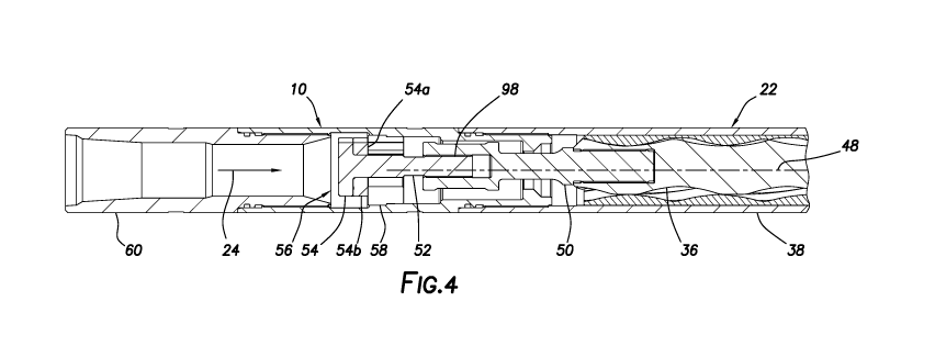
In FIGS. 4-6, various views of the pulse generator 10 connected at an upper
end of the
fluid motor 22 are representatively illustrated. In these views, it may be
seen that the pulse
generator 10 includes an inner mandrel 50 rigidly connected at an upper end of
the rotor 36.
Thus, the inner mandrel 50 rotates and revolves with the rotor 36 about the
central axis 48. In
some examples, the inner mandrel could be integrally formed with the rotor 36.
An upper end of the inner mandrel 50 is internally splined. A shaft 52 of a
restrictor
member 54 is externally splined, and is slidingly received in the upper end of
the inner mandrel
50. The splined longitudinally variable length connection 98 between the inner
mandrel 50 and
the restrictor member shaft 52 permits rotation and torque to be transmitted
from the rotor 36 to
the restrictor member 54, while providing for a variable longitudinal distance
between the rotor
and the restrictor member.
Other types of variable length connections may be used to transmit rotation
and torque
from the rotor 36 to the restrictor member 54. For example, a key carried on
the shaft 52 or in
the inner mandrel 50 could be slidingly engaged in a longitudinally extending
slot formed in the
other of them. Thus, the scope of this disclosure is not limited to use of any
particular type of
variable length connection.
The restrictor member 54 is a component of a variable flow restrictor 56 of
the pulse
generator 10. The variable flow restrictor 56 variably restricts or obstructs
the flow of the fluid
24 through the pulse generator 10. The variable flow restrictor 56 in this
example includes the
restrictor member 54 and a ported member 58.
The variable length connection 98 between the inner mandrel 50 and the
restrictor
member shaft 52 allows the flow of the fluid 24 to bias the restrictor member
54 against an
upper face of the ported member 58. This surface contact between the
restrictor member 54
and the ported member 58 facilitates generation of desired variations in the
flow of the fluid 24
by restricting leakage of fluid between contacting surfaces of the restrictor
member and ported
member.
The pulse generator 10 includes an outer housing assembly 60 that contains the
variable flow restrictor 56 and an upper portion of the inner mandrel 50. The
outer housing
assembly 60 is connected to the stator housing 38 of the fluid motor 22.
Rotation of the restrictor member 54 relative to the ported member 58 by the
rotor 36
causes the restriction to flow of the fluid 24 through the pulse generator 10
to repeatedly vary
between substantially unrestricted and substantially restricted
configurations. In other
examples, the ported member 58 could be rotated relative to the restrictor
member 54 in order
CA 03171350 2022-08-15
WO 2021/178786 PCT/US2021/021065
- 8 -
to vary the restriction to fluid flow. Thus, the scope of this disclosure is
not limited to rotation by
the rotor 36 of any specific member of the variable flow restrictor 56.
In FIGS. 7-10, an example of the restrictor member 54 and the ported member 58
are
representatively illustrated, apart from the rest of the pulse generator 10.
In these views, it may
be seen that this example of the restrictor and ported members 54, 58 are
uniquely configured
to provide for substantially unrestricted flow of the fluid 24 through the
pulse generator 10
during a majority of a rotation cycle, and to provide for substantially
restricted flow only during a
small minority of the rotation cycle.
In FIG. 7, it may be seen that the ported member 58 has an external shoulder
62 formed
thereon. The shoulder 62 abuts an internal shoulder in the outer housing
assembly 60, so that
the ported member 58 is prevented from displacing longitudinally past the
internal shoulder. In
some examples, the ported member 58 could be press-fit or otherwise secured in
the outer
housing assembly 60, in order to prevent relative rotation between the ported
member and the
outer housing assembly.
An upper face 58a of the ported member 58 has a semi-circular groove or recess
58b
formed therein. In some examples, the recess 58b may extend greater than 180
degrees about
a central bore 58c formed through the ported member 58. Multiple ports 58d
extend between
the recess 58b and a lower face 58e (see FIG. 6) of the ported member 58. The
ports 58d
permit fluid communication between the recess 58b in the pulse generator 10
and the fluid
motor 22 below (downstream of) the variable flow restrictor 56.
In FIG. 8, it may be seen that the restrictor member 54 only partially
overlaps the upper
face 58a of the ported member 58. When any of the recess 58b is not blocked by
the restrictor
member 54, the recess allows the fluid 24 to flow through all of the ports
58d. Thus, the
restriction to flow of the fluid 24 through the variable flow restrictor 56 is
dependent on how
much of the recess 58b is blocked by the restrictor member 54.
FIG. 8 also depicts an example of how the restrictor member 54 rotates and
revolves
relative to the ported member 58. The restrictor member 54 rotates about its
longitudinal axis
66 in a clockwise direction viewed from above, as indicated by arrow 64. The
rotor 36 and inner
mandrel 50 also rotate in this direction. The restrictor member 54 revolves
about the central
axis 48 in a counterclockwise direction viewed from above, as indicated by
arrow 68. The rotor
36 and inner mandrel 50 also revolve about the axis 48 in this direction. In
other examples, the
restrictor member 54 could rotate about its longitudinal axis 66 in a
counterclockwise direction
and the restrictor member could revolve about the central axis 48 in a
clockwise direction.
An upper section of the restrictor member 54 is generally cylindrical shaped,
but it has a
circumferentially extending recess 70 formed in a section of its outer
circumference. In this
CA 03171350 2022-08-15
WO 2021/178786 PCT/US2021/021065
- 9 -
example, the recess 70 extends less than 180 degrees about the outer
circumference of the
restrictor member 54.
In FIGS. 9 & 10, the variable flow restrictor 56 is depicted in respective
maximally and
minimally restricted or obstructed configurations. In FIG. 9, it may be seen
that the restrictor
member 54 is in a position in which it obstructs a large majority of a flow
area through the upper
face 58a of the ported member 58. In this position, flow of the fluid 24
through the variable flow
restrictor 56 is at a minimum.
In FIG. 10, it may be seen that the restrictor member 54 is in a position in
which a large
majority of the flow area through the upper face 58a of the ported member 58
is not obstructed
by the restrictor member. In this position, flow of the fluid 24 through the
variable flow restrictor
56 is at a maximum.
Referring additionally now to FIG. 11, a sequence of positions of the
restrictor member
54 relative to the ported member 58 for a complete 360 degree rotation of the
restrictor member
are representatively illustrated. Note that the restrictor member 54 in this
example displaces
from the maximally restricted configuration to the minimally restricted
configuration, and then
back to the maximally restricted configuration, over a full cycle comprising
360 degrees of
rotation.
Note that it is desirable in this example for a lower face 54a of the
restrictor member 54
(see FIG. 4) to be in contact with the upper face 58a of the of the ported
member 58 for
effective variation of the restriction to flow through the variable flow
restrictor 56. Preferably, the
restrictor member 54 and ported member 58 are made of durable erosion
resistant and wear
resistant materials, or at least the lower face 54a and upper face 58a
comprise such materials.
Note, also, that the flow of the fluid 24 through the variable flow restrictor
10 tends to
bias the restrictor member 54 against the ported member 58, thereby increasing
a bearing
stress between the lower face 54a and the upper face 58a. The splined
connection 98 between
the shaft 52 and the inner mandrel 50 permits the restrictor member 54 to
displace in the
direction of the flow.
In the FIGS. 2-11 example, the restrictor member 54 includes a lower portion
54b that is
made of a carbide material. An upper portion of the ported member 58 could
similarly be made
of a carbide material. Alternatively, the lower and upper faces 54a, 58a could
have a hard
facing material applied to them using any of a variety of different processes.
Any technique for
preventing or reducing wear between the faces 54a, 58a may be used in keeping
with the
principles of this disclosure.
Alternatively, one of the faces 54a, 58a could be made of a material that is
designed to
gradually wear away as the variable flow restrictor 56 is operated downhole.
In this alternative,
the face 54a or 58a could be replaced after it is sufficiently worn (perhaps
after each use).
CA 03171350 2022-08-15
WO 2021/178786 PCT/US2021/021065
- 10 -
Referring additionally now to FIGS. 12-17, another example of the pulse
generator 10 is
representatively illustrated. In this example, the restrictor member 54
rotates about the central
axis 48, but does not revolve about the central axis (e.g., in a hypo-cyclic
or epicyclic motion)
as in the FIGS. 2-11 example.
In the FIGS. 12-17 example, a flex joint 72 is used in place of the inner
mandrel 50. The
flex joint 72 is connected at its upper end to the restrictor member 54 using
a splined or other
longitudinally variable distance connection 98, and is connected at its lower
end to the upper
end of the rotor 36. The flex joint 72 in this example can be made of a
titanium material with
pressed-on steel end portions. However, the scope of this disclosure is not
limited to use of any
particular materials for any particular components of any of the variable flow
restrictor examples
described herein.
The lower end of the flex joint 72 rotates and revolves with the rotor 36
about the central
axis 48. However, a flexibility of the flex joint 72 allows the upper end of
the flex joint to be
constrained by a bearing assembly 74, so that it only rotates about the
central axis 48. Note
that ports 74a are formed through the bearing assembly 74 to provide for flow
of the fluid 24
through the bearing assembly.
In FIGS. 16 & 17, it may be seen that the restrictor member 54 has a recess
54c formed
in the lower face 54a, and multiple ports 54d extending through the restrictor
member. In this
example, the recess 54c extends more than 180 degrees about the shaft 52,
whereas the
recess 58b in the upper face 58a extends less than 180 degrees about the
central bore 58c.
The restriction to flow of the fluid 24 through the variable flow restrictor
56 is determined by how
much the recesses 54c, 58b overlap as the restrictor member 54 rotates
relative to the ported
member 58.
Referring now to FIGS. 18 & 19, another example of the pulse generator 10 is
representatively illustrated. In this example, a universal joint or constant
velocity joint assembly
76 is connected between the rotor 36 and the restrictor member 54 in place of
the flex joint 72
of the FIGS. 12-17 example.
The lower end of the joint assembly 76 rotates and revolves with the rotor 36
about the
central axis 48. However, the joint assembly 76 allows the upper end of the
joint assembly to be
constrained by the bearing assembly 74, so that it only rotates about the
central axis 48.
Operation of the FIGS. 18 & 19 example is substantially similar to the
operation of the FIGS.
12-17 example.
Referring now to FIGS. 20-32, another example of the pulse generator 10 is
representatively illustrated. In this example, the variable flow restrictor 56
is configured so that
the restrictor member 54 rotates within the ported member 58.
CA 03171350 2022-08-15
WO 2021/178786 PCT/US2021/021065
- 11 -
The restrictor member 54 is press-fit or otherwise secured onto an upper end
of the flex
joint 72, which is connected between the restrictor member and the rotor 36.
In other examples,
the constant velocity joint 76 may be used in place of, or in addition to, the
flex joint 72.
As depicted in FIGS. 20-22, the restrictor member 54 is received in the ported
member
58. An upper end of the ported member 58 is closed off, except that a
passageway and/or port
58d extends through a side wall of the ported member. The port 58d allows the
fluid 24 to flow
to an interior of the ported member 58.
The restrictor member 54 periodically obstructs the port 58d, thereby
restricting the flow
of the fluid 24 through the variable flow restrictor 56. As depicted in FIG.
21, the restrictor
member 54 is rotated to a position in which the port 58d is not obstructed by
the restrictor
member, and so maximum flow of the fluid 24 through the variable flow
restrictor 56 is
permitted. In FIG. 22, the restrictor member 54 is rotated to a position in
which the port 58d is
most obstructed by the restrictor member, and so minimal flow of the fluid 24
through the
variable flow restrictor 56 is permitted.
FIGS. 23-32 depict various views of the restrictor member 54. In these views,
it may be
seen that the restrictor member 54 is configured to permit relatively
unobstructed flow of the
fluid 24 through the variable flow restrictor 56 during most of the rotation
of the restrictor
member.
Flow of the fluid 24 is substantially restricted by the variable flow
restrictor 56 only
during a small portion of the rotation of the restrictor member 54 relative to
the ported member
58. A relatively small recess or channel 100 formed in an upper portion of the
restrictor member
54 allows a small amount of the fluid to flow through the fluid pulse
generator 10, even when
the restrictor member obstructs the port 58d.
Note that the splined connection 98 is not used in the FIGS. 20-32 example.
However,
the restrictor member 54 can longitudinally displace somewhat relative to the
ported member
58, for example, to accommodate longitudinal displacement of the rotor 36
relative to the stator
housing 38.
Another example of the fluid pulse generator 10 is representatively
illustrated in FIGS.
60-61B. In this example, the restrictor member 54 is rotated externally to
(e.g., circumferentially
about) the ported member 58. The restrictor member 54 includes an extension
54e that
obstructs or blocks flow through the port 58d in the ported member 58, but
only in a minority of
a cycle of rotation of the restrictor member.
The restrictor member extension 54e periodically obstructs the port 58d,
thereby
restricting the flow of the fluid 24 through the variable flow restrictor 56.
As depicted in FIG.
61A, the restrictor member 54 is rotated to a position in which the port 58d
is obstructed by the
restrictor member extension 54e, and so minimal flow of the fluid 24 through
the variable flow
CA 03171350 2022-08-15
WO 2021/178786 PCT/US2021/021065
- 12 -
restrictor 56 is permitted. In FIG. 61B, the restrictor member 54 is rotated
to a position in which
the port 58d is not obstructed by the restrictor member extension 54e, and so
maximum flow of
the fluid 24 through the variable flow restrictor 56 is permitted.
Referring additionally now to FIGS. 33-49, another example of the fluid pulse
generator
and system 12 is representatively illustrated. In this example, the fluid
motor 22 drives a
valve 80 that alternately prevents and permits flow through a bypass flow path
82. The bypass
flow path 82 is in parallel with a flow path 84 through a fluidic restrictor
element 86.
The fluidic restrictor element 86 may comprise any fluidic device capable of
restricting
fluid flow in response to the fluid flow through the fluidic device. Examples
of suitable fluidic
devices are described in US patent nos. 8381817, 8439117, 8453745, 8517105,
8517106,
8517107, 8517108, 9212522, 9316065, 9915107, 10415324 and 10513900. The entire
disclosures of these US patents are incorporated herein by this reference.
As depicted in FIG. 33, the fluid 24 can flow into both of the valve 80 and
the fluidic
restrictor element 86. When the valve 80 is open, the fluid 24 will
preferentially flow through the
bypass flow path 82, since it presents less resistance to the flow of the
fluid 24. When the valve
80 is closed, the fluid 24 is forced to flow through the fluidic restrictor
element 86, thereby
variably restricting the flow of the fluid 24 through the fluidic restrictor
element 86.
Note that flow of the fluid 24 is continually permitted through the fluidic
restrictor element
86 and so, even when the valve 80 is closed, the fluid 24 still flows through
the fluid motor 22.
Thus, the fluid motor 22 can continue to drive the valve 80, whether the valve
is open or closed.
In FIGS. 34 & 35, it may be seen that the valve 80 is driven in a manner
similar to the
FIGS. 18 & 19 example, with the constant velocity joint assembly 76 being used
to transmit
rotation from the rotor 36 to an internally splined inner mandrel 50
rotationally supported in the
bearing assembly 74. The flex joint 72 may be used in place of the constant
velocity joint
assembly 76 in other examples.
An externally splined shaft 52 is received in the inner mandrel 50 and is
connected to a
rotary valve element 88. The splined inner mandrel 50 and shaft 52 are the
same as or similar
to the variable length connection 98 described above.
In FIGS. 36 & 37, a rotary valve assembly 90 of the fluid pulse generator 10
is
representatively illustrated. The rotary valve assembly 90 may be used for the
valve 80 of FIG.
33 & 62, although other types of valves may be used for the valve 80 in other
examples.
The rotary valve assembly 90 may alternatively be used for the variable
restrictor 56, for
example, in the FIGS. 1-32 & 60-61B fluid pulse generator 10 embodiments. In
that case, the
rotary valve element 88 corresponds to the restrictor member 54 and the
bearing assembly 74
corresponds to the ported member 58.
CA 03171350 2022-08-15
WO 2021/178786 PCT/US2021/021065
- 13 -
The rotary valve assembly 90 in the FIGS. 36 & 37 example includes the inner
mandrel
50, the bearing assembly 74 and the rotary valve element 88. The rotary valve
element 88
includes a central internal flow passage 88a and an intersecting radially
offset flow passage
88b. The offset flow passage 88b also extends through a portion of a bearing
wear element
88c.
In this example, the wear element 88c can comprise a relatively ductile
bearing material
selected for sliding engagement with an upper face 74b of the bearing assembly
74. Although
the wear element 88c may sustain significant wear during operation of the
fluid pulse generator
10, the wear element can be conveniently replaced during routine maintenance
between jobs.
The bearing wear element 88c is in sliding contact with the upper face 74b of
the
bearing assembly 74. The ports 74a extend longitudinally through the bearing
assembly 74,
and at least one of the ports is open to flow at all times, so that fluid
communication is
continually permitted longitudinally through the bearing assembly 74.
In FIG. 38 it may be seen that a circumferentially extending recess 74c is
formed in the
upper face 74b of the bearing assembly 74. The recess 74c does not extend a
full 360 degrees
in the upper face 74b. The recess 74c does permit fluid communication between
all of the ports
74a in the bearing assembly 74, so that flow is always permitted through all
of the ports.
A portion of the upper face 74b positioned between opposite ends of the recess
74c
provides for blocking flow through the flow passage 88b in the rotary valve
element 88, as
described more fully below. Thus, a circumferential distance between the
opposite ends of the
recess 74c can be varied to correspondingly vary an extent of rotation of the
rotary valve
element 88 during which the flow passage 88b is blocked by the upper face 74b
of the bearing
assembly 74.
Note that the variable length connection 98 between the shaft 52 and the inner
mandrel
50 permits the rotary valve element 88 to be biased into contact with the
bearing assembly 74
by the flow of the fluid 24. Preferably, the rotary valve element 88 is
configured so that bearing
stress between the wear element 88c and the upper face 74b of the bearing
assembly 74 is
acceptably low to thereby reduce wear at this interface, while still
permitting flow through the
passages 88a,b to be blocked by the upper face 74b circumferentially between
the ends of the
recess 74c.
In FIGS. 39-41, various views of the bearing assembly 74 are representatively
illustrated. In these views, the manner in which the circumferential recess
74c permits fluid
communication between upper ends of the ports 74a can be clearly seen.
In FIGS. 42 & 43, top views of the rotary valve element 88 in different rotary
positions
relative to the bearing assembly 74 are depicted. In FIG. 42, the rotary valve
element 88 is in a
rotary position in which the flow passage 88b is blocked by the upper face 74b
of the bearing
CA 03171350 2022-08-15
WO 2021/178786 PCT/US2021/021065
- 14 -
assembly 74. In FIG. 43, the rotary valve element 88 is in a rotary position
in which the flow
passage 88b is not blocked by the upper face 74b of the bearing assembly 74.
Note that, no
matter the rotary position of the rotary valve element 88, flow is always
permitted through the
ports 74a.
Another example of the rotary valve assembly 90 is representatively
illustrated in FIGS.
58 & 59. In this example, the upper face 74b of the bearing assembly 74 in
concave frusta-
conical shaped. A lower face 88d of the rotary valve element 88 is
complementarily shaped
(e.g., convex frusta-conical).
The FIGS. 58 & 59 rotary valve assembly 90 operates in a manner similar to
that of the
FIGS. 34-43 example. In addition, the frusta-conical shapes of the upper and
lower faces 74b,
88d helps to align the rotary valve element 88 relative to the bearing
assembly 74.
In FIGS. 44-49, different views of the fluidic restrictor element 86 are
representatively
illustrated. In this example, the fluidic restrictor element 86 comprises no
separately moving
parts, but the fluidic restrictor element is capable of producing variable
resistance to flow in
response to fluid flow through the fluidic restrictor element. The bypass flow
path 82 also
extends through the fluidic restrictor element 86 in this example.
The bypass flow path 82 is in fluid communication with the flow passages 88a,b
in the
rotary valve element 88 (see FIGS. 34 & 35). An upper end of the rotary valve
element 88 may,
for example, be received in a lower end of the fluidic restrictor element 86,
so that the fluid 24
flowing from the bypass flow path flows into the flow passage 88a of the
rotary valve element.
In this example, the fluidic restrictor element 86 includes a vortex chamber
92 having a
central outlet 94. When flow through the bypass flow path 82 is blocked (such
as, when the
rotary valve element 88 is in the rotary position depicted in FIG. 42), the
fluid 24 will flow
through the vortex chamber 92 to the outlet 94, and then through the ports 74a
in the bearing
assembly 74, and then through the fluid motor 22. When the fluid 24 flows
through the vortex
chamber 92, the resistance to the flow of the fluid will alternately increase
and decrease as
rotational flow of the fluid in the vortex chamber alternately increases and
decreases. The
operation of the fluidic restrictor element 86 is more specifically described
in the US patents
referenced above.
When flow through the bypass flow path 82 is not blocked (such as, when the
rotary
valve element 88 is in the rotary position depicted in FIG. 43), the fluid 24
will flow through the
bypass flow path, through the flow passages 88a,b in the rotary valve element
88, and then
through the ports 74a in the bearing assembly 74, and then through the fluid
motor 22. Note
that flow through the vortex chamber 92 is continually permitted in this
example, but the fluid 24
preferentially flows through the bypass flow path 82 when it is not blocked,
since the bypass
flow path has less resistance to the flow of the fluid.
CA 03171350 2022-08-15
WO 2021/178786 PCT/US2021/021065
- 15 -
In FIGS. 50-52, another example of the fluidic restrictor element 86 is
representatively
illustrated. In this example, the fluidic restrictor element 86 includes the
bypass flow path 82,
the vortex chamber 92 and the outlet 94, but the bypass flow path is in
communication with the
vortex chamber, so that when flow through the bypass flow path is unblocked,
creation of a
vortex in the vortex chamber is prevented.
In FIG. 51, flow of the fluid 24 through the bypass flow path 82 is blocked
(such as,
when the rotary valve element 88 is in the rotary position depicted in FIG.
42, downstream of
the bypass flow path depicted in FIGS. 50-52). As a result, the fluid 24 flows
into the vortex
chamber 92, and then through the outlet 94. A vortex is created in the vortex
chamber 92,
thereby increasing the resistance to flow through the vortex chamber.
In FIG. 52, flow of the fluid 24 through the bypass flow path 82 is unblocked
(such as,
when the rotary valve element 88 is in the rotary position depicted in FIG.
43). As a result, the
fluid 24 can flow unimpeded through the bypass flow path 82, and can also exit
the vortex
chamber 92 without creating a vortex therein (via a flow path 96 in
communication with the
bypass flow path 82, as well as via the outlet 94). Thus, the resistance to
the flow of the fluid 24
through the fluidic restrictor element 86 is much less in FIG. 52 as compared
to FIG. 51.
In FIGS. 53-55 another example of the fluidic restrictor element 86 is
representatively
illustrated. In this example, the fluid 24 preferentially flows through the
bypass flow path 82
when it is unblocked, but the fluid is forced to flow through the vortex
chamber 92 when the
bypass flow path is blocked.
In FIG. 54, flow of the fluid 24 through the bypass flow path 82 is blocked
(such as,
when the rotary valve element 88 is in the rotary position depicted in FIG.
42). As a result, the
fluid 24 flows into the vortex chamber 92, and then through the outlet 94. A
vortex is created in
the vortex chamber 92, thereby increasing the resistance to flow through the
vortex chamber.
In FIG. 55, flow of the fluid 24 through the bypass flow path 82 is unblocked
(such as,
when the rotary valve element 88 is in the rotary position depicted in FIG.
43). As a result, the
fluid 24 can flow unimpeded through the bypass flow path 82. Thus, the
resistance to the flow
of the fluid 24 through the fluidic restrictor element 86 is much less in FIG.
55 as compared to
FIG. 54.
In FIGS. 56 & 57, another example of the fluidic restrictor element 86 is
representatively
illustrated. In this example, the fluidic restrictor element 86 includes the
bypass flow path 82,
the vortex chamber 92 and the outlet 94, but the bypass flow path is in
communication with the
vortex chamber, so that when flow through the bypass flow path is unblocked,
creation of a
vortex in the vortex chamber is prevented.
In FIG. 56, flow of the fluid 24 through the bypass flow path 82 is blocked
(such as,
when the rotary valve element 88 is in the rotary position depicted in FIG.
42). As a result, the
CA 03171350 2022-08-15
WO 2021/178786 PCT/US2021/021065
- 16 -
fluid 24 flows into the vortex chamber 92, and then through the outlet 94. A
vortex is created in
the vortex chamber 92, thereby increasing the resistance to flow through the
vortex chamber.
In FIG. 57, flow of the fluid 24 through the bypass flow path 82 is unblocked
(such as,
when the rotary valve element 88 is in the rotary position depicted in FIG.
43). As a result, the
fluid 24 can flow unimpeded through the bypass flow path 82, and can also exit
the vortex
chamber 92 without creating a vortex therein (via the outlet 94 and the flow
path 96 in
communication with the bypass flow path 82). Thus, the resistance to the flow
of the fluid 24
through the fluidic restrictor element 86 is much less in FIG. 57 as compared
to FIG. 56.
In the examples of FIGS. 33-57, the fluid motor 22 rotates the rotary valve
element 88
via the constant velocity joint assembly 76, the inner mandrel 50 and the
shaft 52. The flex joint
72 may be used in place of the constant velocity joint assembly 76 in other
examples.
As the rotary valve element 88 rotates, flow through the bypass flow path 82
is
unblocked during a majority of each rotation. However, when the flow passage
88b is
positioned between the circumferential ends of the recess 77c, flow through
the passages
88a,b and the bypass flow path 82 is blocked by the upper face 77b of the
bearing assembly
77, so that all of the fluid 24 is forced to flow through the vortex chamber
92 of the fluidic
restrictor element 86.
In the example of FIGS. 44-49, a vortex is alternately created and collapsed
in the
vortex chamber 92, so that the resistance to flow of the fluid 24 through the
vortex chamber
alternately increases and decreases. A frequency and an amplitude of this
alternating flow
resistance can be selected by appropriate configuration of the vortex chamber
92 and
associated flow paths in communication with the vortex chamber.
In the examples of FIGS. 50-57, a vortex is created in the vortex chamber 92
when flow
through the bypass flow path 82 is blocked. This increases the resistance to
flow of the fluid 24
through the vortex chamber 92. An amplitude of this increased flow resistance
can be selected
by appropriate configuration of the vortex chamber 92 and associated flow
paths in
communication with the vortex chamber.
When flow through the bypass flow path 82 is unblocked, the resistance to the
flow of
the fluid 24 is substantially decreased. In the examples of FIGS. 44-49 & 53-
55, the flow is
preferentially through the bypass flow path 82, so that only a minimal amount
of the fluid 24
flows through the vortex chamber 92, although a vortex can still be created in
the vortex
chamber.
In the examples of FIGS. 50-52, 56 & 57, creation of a vortex in the vortex
chamber 92
is prevented when the bypass flow path 82 is unblocked. This is due to the
flow path 96 which
connects the vortex chamber 92 to the bypass flow path 82.
CA 03171350 2022-08-15
WO 2021/178786 PCT/US2021/021065
- 17 -
Thus, as the rotary valve element 88 is rotated by the fluid motor 22, the
resistance to
flow of the fluid 24 is increased (alternating as in the FIGS. 44-49 example,
or steady state as in
the FIGS. 50-57 examples) when the bypass flow path 82 is blocked, and the
resistance to flow
of the fluid is decreased when the bypass flow path is unblocked.
Referring additionally now to FIG. 62, another example of the fluid pulse
generator 10 is
representatively illustrated. The FIG. 62 example is similar in many respects
to the FIG. 33
example. However, the FIG. 62 fluid pulse generator 10 includes an additional
bypass flow path
102 connected in parallel with the bypass flow path 82 and the flow path 84.
The bypass flow path 102 allows the fluid 24 to flow past both of the valve 80
and the
fluidic restrictor element 86. This can be useful when it is not desired for
the fluid pulse
generator 10 to generate fluid pulses, for example, when conveying the drill
string 14 into or out
of a vertical section of the wellbore 16 (see FIG. 1).
When it is desired to generate fluid pulses, the bypass flow path 102 can be
blocked to
thereby force the fluid 24 to flow through the bypass flow path 82 and the
flow path 84 as
described above for the FIG. 33 example. In order to block the bypass flow
path 102, a plug
104 (such as, a ball, a dart, etc.) can be deployed into the bypass flow path
102, so that the
plug engages a seat 106 therein, as depicted in FIG. 63.
In the FIG. 63 example, the fluid pulse generator 10 includes an excluder 108
that
prevents the plug 104 from entering the bypass flow path 82 or the flow path
84, but allows the
plug to enter the bypass flow path 102. A filter or slot 110 in the excluder
108 permits the fluid
24 to flow into the bypass flow path 82 and the flow path 84 at all times, but
the slot is narrower
than a width of the plug 104, so that the plug is excluded from passing
through the slot.
It may now be fully appreciated that the above disclosure provides significant
advancements to the art of generating fluid pulses in subterranean wells. In
various examples
described above, a fluid pulse generator 10 generates fluid pulses in response
to fluid flow 24
through the fluid pulse generator and a fluid motor 22 connected downstream of
the fluid pulse
generator.
The above disclosure provides to the art a fluid pulse generator 10 for use
with a
subterranean well. In one example, the fluid pulse generator 10 can include a
fluid motor 22
including a rotor 36 configured to rotate in response to fluid flow 24 through
the fluid motor 22, a
variable flow restrictor 56 positioned upstream of the fluid motor 22, the
variable flow restrictor
56 including a restrictor member 54 rotatable by the rotor 36 relative to a
ported member 58 to
thereby variably restrict the fluid flow 24. The restrictor member 54 is
longitudinally displaceable
relative to the rotor 36.
A variable length connection 98 may transmit rotation and torque from the
rotor 36 to the
restrictor member 54. The variable length connection 98 may comprise a splined
connection.
CA 03171350 2022-08-15
WO 2021/178786 PCT/US2021/021065
- 18 -
The fluid flow 24 may bias the restrictor member 54 against the ported member
58. A
bearing stress between surfaces 54a, 58a of the restrictor member 54 and the
ported member
58 may increase in response to the fluid flow 24. The surfaces 88d, 74b of the
restrictor
member (e.g., the rotary valve element 88) and the ported member (e.g., the
bearing assembly
74) may be frusta-conical shaped, for example, as depicted in FIG. 58.
A flow area for the fluid flow 24 through the variable flow restrictor 56 may
be more than
fifty percent open in a majority of each cycle of rotation of the restrictor
member 54. A flow area
for the fluid flow 24 through the variable flow restrictor 56 may be less than
fifty percent open in
a minority of each cycle of rotation of the restrictor member 54.
At least one of a flex joint 72 and a constant velocity joint 76 may be
connected between
the restrictor member 54 and the rotor 36.
The restrictor member 54 may rotate and revolve about a central longitudinal
axis 66 of
the fluid motor 22.
A bearing section 30 may be connected to the rotor 36 on a side of the rotor
36 opposite
the variable flow restrictor 56.
Another example of the fluid pulse generator 10 can comprise a fluid motor 22
including
a rotor 36 configured to rotate in response to fluid flow 24 through the fluid
motor 22, a variable
flow restrictor 56 positioned upstream of the fluid motor 22, the variable
flow restrictor 56
including a restrictor member 54 rotatable by the rotor 36 relative to a
ported member 58 to
thereby variably restrict the fluid flow 24, and at least one of a flex joint
72 and a constant
velocity joint 76 connected between the restrictor member 54 and the rotor 36.
A splined connection 98 may be connected between the restrictor member 54 and
the
flex joint 72 or the constant velocity joint 76. A variable length connection
98 may transmit
rotation and torque from the rotor 36 to the restrictor member 54.
The fluid flow 24 may bias the restrictor member 54 against the ported member
58. A
bearing stress between surfaces 54a, 58a of the restrictor member 54 and the
ported member
58 may increase in response to the fluid flow 24.
The ported member 58 may outwardly surround the restrictor member 54, for
example,
as depicted in FIGS. 20-32. The restrictor member 54 may be circumferentially
rotatable about
the ported member 58, for example, as depicted in FIGS. 60-61B.
The restrictor member 54 may periodically block the fluid flow 24 radially
through the
ported member 58. The restrictor member 54 may be longitudinally displaceable
within the
ported member 58.
CA 03171350 2022-08-15
WO 2021/178786 PCT/US2021/021065
- 19 -
The restrictor member 54 may block a port 58d formed through the ported member
58
less than fifty percent of a cycle of rotation of the restrictor member 54.
The fluid flow 24 may
be continually permitted through the variable flow restrictor 56.
Another fluid pulse generator 10 can comprise a fluid motor 22 including a
rotor 36
configured to rotate in response to fluid flow 24 through the fluid motor 22,
and a variable flow
restrictor 56 positioned upstream of the fluid motor 22, the variable flow
restrictor 56 including a
valve 80, 90 and a fluidic restrictor element 86, and the valve 80, 90 being
operable in response
to rotation of the rotor 36. The fluidic restrictor element 86 is configured
to generate fluid pulses
in response to the fluid flow 24 through a first flow path 84, and the valve
80, 90 is configured to
control the fluid flow 24 through a second flow path 82 connected in parallel
with the first flow
path 84.
The first and second fluid paths 84, 82 may be connected upstream of the fluid
motor
22.
The rotor 36 may be connected to a rotary valve element 88 of the valve 80,
90. The
rotor 36 may rotate the rotary valve element 88 relative to a ported bearing
assembly 74 in
response to the fluid flow 24.
At least one of a flex joint 72 and a constant velocity joint 76 may be
connected between
the rotor 36 and the rotary valve element 88. A splined connection 98 may be
connected
between the rotary valve element 88 and the flex joint 72 or the constant
velocity joint 76. A
variable length connection 98 may transmit rotation and torque from the rotor
36 to the rotary
valve element 88.
The second flow path 82 may extend through the fluidic restrictor element 86.
The fluid
flow 24 may enter the second flow path 82 upstream of a vortex chamber 92 of
the fluidic
restrictor element 86, and the fluid flow 24 may exit the second flow path 82
downstream of the
vortex chamber 92. The fluid flow 24 through the second flow path 82 may
prevent generation
of the fluid pulses by the fluidic restrictor element 86.
A third flow path 102 may be connected in parallel with the first and second
flow paths
84, 82. The fluid flow 24 through the third flow path 102 may prevent
generation of the fluid
pulses by the fluidic restrictor element 86.
A seat 106 may be formed in the third flow path 102. The seat 106 may be
blocked by a
plug 104 to prevent the fluid flow 24 through the third flow path 102.
Although various examples have been described above, with each example having
certain features, it should be understood that it is not necessary for a
particular feature of one
example to be used exclusively with that example. Instead, any of the features
described above
and/or depicted in the drawings can be combined with any of the examples, in
addition to or in
substitution for any of the other features of those examples. One example's
features are not
CA 03171350 2022-08-15
WO 2021/178786 PCT/US2021/021065
- 20 -
mutually exclusive to another example's features. Instead, the scope of this
disclosure
encompasses any combination of any of the features.
Although each example described above includes a certain combination of
features, it
should be understood that it is not necessary for all features of an example
to be used. Instead,
any of the features described above can be used, without any other particular
feature or
features also being used.
It should be understood that the various embodiments described herein may be
utilized
in various orientations, such as inclined, inverted, horizontal, vertical,
etc., and in various
configurations, without departing from the principles of this disclosure. The
embodiments are
described merely as examples of useful applications of the principles of the
disclosure, which is
not limited to any specific details of these embodiments.
In the above description of the representative examples, directional terms
(such as
"above," "below," "upper," "lower," "upward," "downward," etc.) are used for
convenience in
referring to the accompanying drawings. However, it should be clearly
understood that the
scope of this disclosure is not limited to any particular directions described
herein.
The terms "including," "includes," "comprising," "comprises," and similar
terms are used
in a non-limiting sense in this specification. For example, if a system,
method, apparatus,
device, etc., is described as "including" a certain feature or element, the
system, method,
apparatus, device, etc., can include that feature or element, and can also
include other features
or elements. Similarly, the term "comprises" is considered to mean "comprises,
but is not limited
to."
Of course, a person skilled in the art would, upon a careful consideration of
the above
description of representative embodiments of the disclosure, readily
appreciate that many
modifications, additions, substitutions, deletions, and other changes may be
made to the
specific embodiments, and such changes are contemplated by the principles of
this disclosure.
For example, structures disclosed as being separately formed can, in other
examples, be
integrally formed and vice versa. Accordingly, the foregoing detailed
description is to be clearly
understood as being given by way of illustration and example only, the spirit
and scope of the
invention being limited solely by the appended claims and their equivalents.