Note: Descriptions are shown in the official language in which they were submitted.
WO 2021/198943
PCT/IB2021/052681
1
"SYSTEM FOR EXHAUST GAS PURIFICATION OF ENDOTHERMIC
ENGINES"
*.*.*
FIELD OF THE INVENTION
The present invention concerns a system for exhaust gas purification of
endothermic
engines. In particular, such purification system is used in the motoring
sector for
endothermic engines powered both by liquid and gaseous fuels or combustibles,
i.e.
for supercharged and atmospheric Otto cycle and Diesel cycle engines with two
and
four strokes, with both carburetor and direct and indirect injection.
KNOWN PRIOR ART
According to known art, the systems for exhaust gas purification of an
endothermic
engine in use are not able to effectively purify the exhaust gases produced by
the
engine itself, thus releasing gaseous and solid substances that are highly
toxic to the
health into the air. The most renown purification systems are known under the
acronyms DPF and FAP.
The diesel particulate filter (whether of the FAP or DPF type), inserted into
the
exhaust system and integrated with the catalyst or catalytic converter,
consists of a
monolithic support based on porous silicon carbide. This allows to reduce the
size of
the particulate matter particles emitted to less than one thousandth, also
taking into
account the particles of smaller sizes (<20 nm).
The diesel particulate filter is to be regarded as a real mechanical filter
consisting of
a series of channels on whose surfaces the particulate matter is trapped,
while the
exhaust gases cross its porous walls.
The diesel particulate filters are thus real "mechanical traps" where the
powders are -
in fact - "trapped". For this reason, these diesel particulate filters require
periodic
cleaning since the "trap" channels get obstructed with particulate matter.
Such
cleaning is named regeneration. The regeneration is a flame development which
triggers a combustion process of the particulate matter inside the filter,
i.e. the
process of incinerating and reducing the size of particulate matter. On the
average,
such process occurs every 800/1000 kilometers and, in urban use, even at
intervals of
less than 300 kilometers. Two types of particulate filter systems are
essentially used
CA 03171440 2022- 9- 12
WO 2021/198943
PCT/1B2021/052681
2
by engineers: FAP or DPF. These two types of filtering systems are different
in terms
of their structure and operation. The major difference essentially lies in the
different
regeneration strategy
The particulate filter system named FAP (Filtres a Particules) belongs to the
type of
filters that use various additives based on cerium and/or iron oxides to be
regenerated, whereas the particulate filter system named DPF (Diesel
Particulate
Filter) does not use additives. However, in both cases during the regeneration
process, i.e. during the combustion of the particulate matter present in the
filter, in
particular in the post-combustion device, the exhaust gases can reach and
exceed
550 C.
Such known filtering systems are thus not able to effectively purify the gases
themselves, thus releasing gaseous and solid substances that are highly toxic
to the
health into the air, but even - following the combustion process - produce
nanoparticles of particulate matter since further reduced in terms of size,
with the
consequence that such particles, further reduced in size, can easily reach the
pulmonary alveoli of the respiratory tract, thus ending up in the blood and in
all other
internal organs of the individuals breathing them. In addition to this, there
is the
release of highly toxic water vapor (a source of acid rains among other
things) into
the atmosphere since mixed with other gaseous pollutants, such as, by way of
example and without limitations, cerine (cerium oxide) which tends to lower
the
flash point of the particulate matter, or the urea (carbonic acid diamide)
used by
modern catalysts for the containment of Nox in an attempt to solve the problem
of
pollutants present in the exhaust gases of Diesel and Otto cycle engines.
Moreover, the fact that, by activating post-combustion functions of exhaust
gases,
such anti-pollution devices (FAP and/or DPF) produce significant increases in
the
operating temperatures of the combustion chambers, thus of the exhaust gases
and
the entire exhaust line which reach and exceed 5500 just at the post-
combustion
device (FAP/DPF), in some cases causing the device and the entire machine to
catch
on fire and in any case a potential risk of the system and machine on which
the
device is installed to catch on fire, must be added.
Such known systems thus have the drawback of making particulate powders
invisible
CA 03171440 2022- 9- 12
WO 2021/198943
PCT/1B2021/052681
3
and easily to inhale, using and vaporizing chemical substances in the
environment,
and amplifying the operating temperatures of the engine, exhaust line and
surrounding environment
Other systems for exhaust gas purification of known art or the like are known.
For example, the patent W02019/196969, in the name of Werner Lohberg describes
a catalytic converter for an internal combustion engine for recovering energy
from
the combustion of fuel and air, wherein the combustion gas being generated is
conducted in a transit path through the catalytic converter along which a
diffusion
membrane resistant to high temperatures is fixed and which in turn borders a
gas
recovery collector which is kept at a lower pressure with respect to a
respective
internal pressure of the catalytic converter and any gas recovered and
collected from
the combustion gas, is restored to the combustion chamber of the engine (M) to
lower its operating temperature and thus the formation of further NOx. A swirl
chamber is inserted in the transit path and is adjacent to the diffusion
membrane. The
internal pressure of the catalytic converter is higher in the swirl chamber as
a result
of the obstacles for the combustion gases. The water is added to the
combustion gas
in the transit path upstream of the swirl chamber, in a ratio according to the
fuel
burned. The water is recovered by cooling the exhaust gases along the exhaust
line of
the engine.
The patent DE3002871, in the name of BRUNN GMBH describes a method of
purifying the exhaust gases from an internal combustion engine, such as a
diesel
engine, by cooling the exhaust gases below their dew point and, thus, by
separating
the liquid produced and the solid particles contained in the exhaust gases.
The
equipment for carrying out the method comprises an exhaust duct having a
cooling
surface connected to a cooling circuit of, for example, a refrigerator, and a
liquid
separator having absorption agents that are used to further separate the solid
particles.
The patent W02020/049184, in the name of INSTRACTION GMBH, instead
concerns a device for purifying drinking water - not exhaust gases of
endothermic
engines - in more steps by combining purifying technologies into a module.
Object of the present invention is thus to implement a system for purifying
exhaust
CA 03171440 2022- 9- 12
WO 2021/198943
PCT/1B2021/052681
4
gases of endothermic engines which has less use risks, in particular, which
does not
involve fire risks for the car on which it is installed.
Further object of the present invention is to implement a purification system
which is
more efficient than known ones and which thus leads to an abatement of the
pollutants emitted by endothermic engines with considerable benefits for the
health
of people.
Moreover, object of the present invention is to implement a purification
system
which can simply be applied also on cars currently in circulation, thus
without
needing to install it during the production step of the car.
SUMMARY OF THE INVENTION
These and further objects are reached by means of a system for the
purification of
exhaust gases of an endothermic engine, comprising at least one duct for
exhausting
the gases produced by said endothermic engine, cooling means for cooling said
exhaust gases which cross said duct so that to cause, at least in part, the
condensation
of the water vapor contained in said exhaust gases in water at least at one
area of said
exhaust duct, and means for separating the condensed water, which is condensed
by
said cooling means along the exhaust duct, from the exhaust gases and for
deviating
it along a secondary duct, said system being characterized by further
comprising
filtering means, which are arranged downstream of said separating means along
said
secondary duct, for filtering said condensed and separated water.
Such solution allows to recover a high amount of polluting powders present in
exhaust gases and of CO and/or CO2 which dissolves in water and which remains
trapped in the water itself following the separation obtained by the
separating means.
The filtering means are then able to fully purify the condensed and separated
water,
thus eliminating, following the separation, both the polluting powders that
had
remained in the condensed water and the polluting gases, which dissolve in the
water.
According to the invention, the purification system further comprises
injecting means
for injecting purified water into said exhaust duct, upstream of said cooling
means,
wherein said injecting means inject said purified water obtained from said
injecting
means at the inlet of said at least one area of said exhaust duct.
CA 03171440 2022- 9- 12
WO 2021/198943
PCT/1B2021/052681
Such solution allows to exploit at least part of the purified water to carry
out an
injection and consequent nebulization of the purified water into the exhaust
duct,
upstream of the area of the exhaust duct where the cooling means operate The
injection of perfectly purified water not only allows to favor the cooling of
exhaust
5 gases
but also facilitates the "capture" of inert particles (or polluting powders)
present in exhaust gases and in gases soluble in the water itself, such as CO
and CO2,
thanks to the nebulization of the purified water.
Moreover, said cooling means comprise a closed circuit inside which a
refrigerant
fluid circulates, preferably but not limitedly the R1234YF mixture; said
closed
circuit comprises at least one first heat exchange length, arranged at said
area, for
exchanging heat with said exhaust duct so that to directly or indirectly
cause, at least
in part, the condensation of the water vapor contained in said exhaust gases.
Moreover, said cooling means comprise, along said closed circuit, a compressor
and
a gas expansion valve, wherein said compressor is downstream of said first
heat
exchange length and said expansion valve is upstream of said at least one
first heat
exchange length.
Moreover said separating means comprise at least one centrifuge, preferably of
the
conical type and, even more preferably of the two-stage type.
According to a preferred embodiment of the invention, the system comprises one
or
more collection tanks for collecting the condensed and separated water, which
are
functionally arranged downstream of said separating means along said secondary
duct, between said separating means and said filtering means of said condensed
and
separated water.
Moreover, said filtering means for filtering said condensed and separated
water
comprise at least one activated carbon filter and/or at least one filter
containing
cationic resin and/or at least one sedimentation filter.
Such activated carbon filter and/or such filter containing cationic resin
and/or such
sedimentation filter can be replaced after a predetermined number of
kilometers
traveled by the car on which the purification system is installed. In
practice, by
simply replacing the activated carbon filter and/or the filter containing the
cationic
resin and/or a sedimentation filter, it is possible to provide to the regular
maintenance
CA 03171440 2022- 9- 12
WO 2021/198943
PCT/1B2021/052681
6
of the purification device.
Moreover, according to a preferred embodiment of the invention, said injecting
means comprise at least one connection duct for directly or indirectly
connecting said
filtering means to said exhaust duct, at least one injector arranged upstream
of said
area of said exhaust duct, and at least one pump for supplying the purified
water to
said at least one injector.
Moreover, at least one collection tank for collecting from said filtering
means said
purified water used by said injecting means, is functionally arranged between
said
injecting means and said filtering means.
Always according to the invention, said separating means are adapted to direct
said
exhaust gases devoid at least in part of said condensed water, along an end
length of
said exhaust duct. Advantageously, said system comprises at least one
filtering
device comprising at least one impregnated activated carbon filter and/or at
least one
absolute filter of the HEPA type, preferably of the H14 type or higher,
arranged
along said end length of said exhaust duct, downstream of said separating
means.
Moreover, said cooling means further comprise a condenser arranged along at
least
one second heat exchange length of said closed circuit; said condenser
comprising
immersion radiator cores and said second heat exchange length crosses a
hermetic
container containing a first coolant. Advantageously, said first refrigerant
liquid
comprises a water and glycol mixture.
The invention also provides a transport vehicle comprising an endothermic
engine, a
system for purifying the exhaust gases coming from said endothermic engine
according to one or more of claims 1 to 12, and a cooling system for cooling
said
endothermic engine, advantageously said cooling system comprises a closed
circuit,
a pump arranged along said closed circuit for circulating a second refrigerant
and
immersion radiator cores arranged inside said hermetic container.
Said second refrigerant liquid advantageously comprises a water and glycol
mixture
Moreover, the transport vehicle comprises a heat exchange system for cooling
said
refrigerant fluid and said second refrigerant liquid; said heat exchange
system
comprises a closed circuit inside which said first refrigerant liquid
circulates, a pump
for circulating said first refrigerant liquid, a refrigeration device for said
first
CA 03171440 2022- 9- 12
WO 2021/198943
PCT/1B2021/052681
7
refrigerant liquid and said hermetic container. Advantageously, said heat
exchange
system comprises a portion for the exchange of heat with said exhaust gases
and with
said first heat exchange length of said refrigeration means
Preferably, said refrigeration device comprises at least one Peltier cell.
Finally, said vehicle comprises an air conditioning device inside the
passenger
compartment, said cooling means of said purification system being functionally
connected to said air conditioning device.
DESCRIPTION OF THE FIGURES
These and further aspects of the present invention will become clearer in the
following detailed description of a preferred embodiment provided herein by
way of
example only and without limitations, with reference to the accompanying
figures, in
which:
Figure 1 is a schematic view of the system for exhaust gas purification
according to
the invention, operating in combination with an endothermic engine of a
transport
vehicle;
Figure 2 is a schematic view of the hermetic container for cooling the
refrigerant
fluid of the cooling means of the exhaust gas and the refrigerant liquid of
the cooling
means of the endothermic engine.
DETAILED DESCRIPTION OF A PREFERRED EMBODIMENT OF THE
PRESENT INVENTION
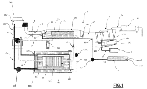
With particular reference to such figures, 1 denotes the system for exhaust
gas
purification according to the present invention.
In an extremely simplified way, some essential components present inside a
generic
transport vehicle 200 are shown in figure 1 for understanding the solution
suggested
in the present patent application. The transport vehicle 200 can be of the
road or
special type, already registered and/or in circulation, and of any size and
type. By
way of example and without limitations, the vehicle 200 could also be for rail
transport and/or anyhow for any vehicle in which an endothermic engine is
used.
The vehicle 200 comprises an endothermic engine 100 of the Diesel cycle type
and a
purification system 1 for the exhaust gases (or exhausted gases) coming from
the
endothermic engine 100.
CA 03171440 2022- 9- 12
WO 2021/198943
PCT/1B2021/052681
8
It should be observed that an endothermic engine of the Otto type would anyhow
fall
within the protection scope of the present invention.
The purification system 1 for the exhaust gases S of the endothermic engine
100
comprises a duct 2 for exhausting the gases produced by the endothermic engine
100
and means 3 for cooling the exhaust gases S which cross the duct 2 so that to
cause,
at least in part, the condensation of the water vapor contained in the exhaust
gases in
condensed water AC at one area 21 of the exhaust duct 2, and means 4 for
separating
the condensed water AC, condensed by the cooling means 3 along the exhaust
duct
2, from the exhaust gases S and for deviating it along a secondary duct 10.
The purification system 1 further comprises filtering means 5, which are
arranged
downstream of said separating means 4 along the secondary duct 10, for
filtering the
condensed and separated water AC.
In this case, the separating means 4 comprise a two-stage centrifuge 50 of the
conical
type. In another embodiment not shown herein, such separating means 4 can
comprise a single-stage centrifuge of the conical type, or a single-stage
centrifuge not
of the conical type, anyhow falling within the protection scope of the present
invention.
Such solution thus allows to filter the water present in the exhaust gas S of
the
combustion engine 100 from impurities. More precisely, the purified water AD
recovered by the effect of the reconversion of the water vapor present in the
exhaust
gases S is centrifuged in the conical two-stage centrifuges, thus forcing all
polluting
particles to mix with the water itself. Said mixing produces an increase in
the weight
and volume of all solid particles and the dissolution of the gaseous ones,
thus
eliminating the possibility to reintroduce them into the air. Such inert
particles are
then restrained by the filtering means 5, thus generating a completely
purified water
AD.
Moreover, the purification system 1 comprises means 30 for injecting the
purified
water AD into the exhaust duct 2 from the filtering means 5. Such injecting
means 3
are able to inject and thus to nebulize the purified water AD, at the
aforementioned
area 21 of the exhaust duct 2. In particular, said injecting means inject the
purified
water AD upstream of the area 21 of the exhaust duct 2.
CA 03171440 2022- 9- 12
WO 2021/198943
PCT/1B2021/052681
9
Such solution thus allows to filter the water present in the exhaust gas S of
the
combustion engine 100 from impurities and to use it, once purified, to capture
further
impurities present in the polluting exhaust gas S More precisely, the purified
water
AD recovered by the effect of the conversion of the water vapor is mixed with
the
exhaust gases S and centrifuged in the conical two-stage centrifuge, thus
forcing all
the polluting particles to mix with the water itself. Moreover, the injection
of water
also allows to favor the cooling of the exhaust gases and the "capture" of
gaseous
and/or inert particles (or polluting powders) present in exhaust gases is
favored,
thanks to the nebulization of the purified water.
According to the embodiment described herein, said cooling means 3 comprise a
closed circuit 40 inside which a refrigerant fluid, such as for example the
R1234YF
mixture, circulates. In further embodiments, such refrigerant fluid can also
be
different from the R1234YF mixture, without thereby departing from the
protection
scope of the present invention. The closed circuit 40 comprises a first heat
exchange
length 41 for exchanging heat with the exhaust duct 2 arranged at the area 21
of the
exhaust duct 2, so that to cause, at least in part, the condensation of the
water vapor
contained in said exhaust gases S. Such heat exchange length can be in direct
or
indirect contact with the exhaust gas S. In practice, the heat exchange length
41 can
comprise a plurality of ducts inside which the refrigerant fluid flows. In the
embodiment described herein, the ducts are not in direct contact with the
exhaust
gases, but a further carrier liquid is cooled along said first heat exchange
length 41
which in turn causes the cooling of the exhaust gases crossing the area 21 of
the
exhaust duct 2. In a further embodiment of the invention, such ducts of the
first heat
exchange length 41 can also be in direct contact with the exhaust gases S.
Moreover, the cooling means 3 comprise, along the closed circuit 40, a
compressor
42 and a gas expansion valve 43, wherein the compressor 42 is downstream of
the
heat exchange length 41 and the expansion valve 43 is upstream of the heat
exchange
length 41.
As shown in figure 1, the purification system 1 comprises two collection tanks
60 for
collecting the condensed and separated water AC, which are functionally
arranged
along the secondary duct 10 between the separating means 4 and the filtering
means
CA 03171440 2022- 9- 12
WO 2021/198943
PCT/1B2021/052681
5 of the condensed water. Such collection tanks 60 are in the initial portion
of such
secondary duct 10.
The number of collection tanks 60 of the condensed and centrifuged waters
depends,
in this case, on the fact that there is a least one two-stage centrifuge 50,
in further
5
embodiments the number of collection tanks 60 of the condensed water could
also be
of a single unit without thereby departing from the protection scope of the
present
invention.
According to the embodiment described herein, said filtering means 5 for
filtering
the condensed and separated water comprise an activated carbon filter, a
filter
10
containing cationic resin and/or a sedimentation filter. Such filters can be
replaced at
the exceeding of a predetermined number of kilometers traveled by the car or
of
operating hours of the machine on which the purification system 1 is
installed.
It should be observed that, although the filtering means 5 described herein
comprise
at least one activated carbon filter, at least one filter containing cationic
resin and at
least one sedimentation filter, in other embodiments the filtering means 5 can
anyhow contain also only one activated carbon filter or also only one cationic
resin
filter or also only one sedimentation filter, or a combination of only two of
such
filters, without thereby departing from the protection scope of the present
invention.
According to the embodiment shown in figure I, such injecting means 30
comprise a
connection duct 31 for directly or indirectly connecting the filtering means 5
to the
exhaust duct 2, an injector 33 arranged upstream of the area 21 of the exhaust
duct 2,
i.e. upstream of the first heat exchange length 41 of the cooling means 3, and
a pump
32 for supplying the purified water AD to the injector 33.
According to the embodiment shown, a collection tank 15 for collecting the
purified
water AD from the filtering means 5 and used by the injecting means 30 is
comprised
between the injecting means 30 and the filtering means 5.
The injection of purified water AD and its consequent nebulization, allows to
bring
forward the cooling of the exhaust gases 41 and to simultaneously capture, at
least
initially, part of the fine inert and polluting powders contained in the
exhaust gas S,
also together with part of the gases which can be dissolved in water, such as
CO2 and
CO.
CA 03171440 2022- 9- 12
WO 2021/198943
PCT/1B2021/052681
11
The excess purified water AD present in the collection container 15 can be
eliminated through an outlet port (not shown herein) which can be opened at
the
exceeding of a predetermined level of purified water AD reached in the
container 15,
as occurs for the condense of the air conditioning systems.
Always as shown in figure 1, the separating means 4 are adapted to direct the
exhaust
gases S devoid at least in part of the condensed water AC, along an end length
2a of
the exhaust duct 2. Moreover, the system 1 comprises a filtering device 80 in
turn
comprising an impregnated activated carbon filter and an absolute filter of
the HEPA
H14 type or higher, which are arranged in series along the end length 2a of
the
exhaust duct 2, downstream of the separating means 4. In further embodiments,
the
filtering device 80 can also comprise only the impregnated activated carbon
filter or
also only an absolute filter of the HEPA H14 type or higher, without thereby
departing from the protection scope of the present invention.
It should be observed that the HEPA filter and the activated carbon filter are
positionable along the end length 2a of the exhaust duct 2 since the exhaust
gases S
reach such section 2a at a temperature of less than 60 C, i.e. at a
temperature not
greater than that to which the filters can resist.
Always according to the embodiment described herein, the cooling means 3
further
comprise a condenser 85 arranged along at least one second heat exchange
length 86
of the closed circuit 40. Such condenser 85 comprises first immersion radiator
cores,
whereas said second section 86 crosses a hermetic container 120 containing a
first
refrigerant liquid. Thus, the condenser 85 is immersed inside the container
120. Such
first refrigerant liquid comprises water and glycol.
The second heat exchange length 86 of the cooling means 3 and the condenser
85,
both immersed inside the hermetic container 120, are shown in figure 2. It is
possible
to see how such second heat exchange length 86 crosses the container 120 and
comprises an inlet section 86a and an outlet section 86b. The refrigerant
fluid
circulating in the circuit 40 enters the section 86a, pushed by the compressor
42 and
then, once condensed, comes out of the section 86b to reach the expansion
valve 43
to then reach the evaporator 41, i.e. the first heat exchange length.
The invention also concerns a vehicle 200 which comprises, in addition to
CA 03171440 2022- 9- 12
WO 2021/198943
PCT/1B2021/052681
12
comprising an endothermic engine 100 and a system 1 for purifying the exhaust
gases 1 coming from the endothermic engine 100 as described above and anyhow
according to one or more of claims 1 to 12, a cooling system 101 for the
endothermic
engine 100. Such cooling system 101 comprises a closed circuit C, a pump 102
arranged along the closed circuit C for circulating a second refrigerant
liquid, such as
for example water and glycol or other refrigerant liquid in further
embodiments, and
radiator cores by immersion 103 arranged inside the hermetic container 120.
Still in figure 2, the radiator cores 103 arranged inside the hermetic
container 120 are
shown. It is possible to see how such radiator cores 103 have an inlet section
103a of
the refrigerant fluid (the outlet section 103b is visible in figure 1) and an
outlet
section 103b. The refrigerant fluid circulating in the circuit C enters from
the section
103a, pushed by the pump 102 and then comes out of the outlet section 103b to
reach
the combustion engine 100 and cause its cooling.
Always as shown in figures 1 and 2, the vehicle 200 further comprises a heat
exchange system for cooling the refrigerant fluid and the second refrigerant
liquid.
Such heat exchange system comprises a closed circuit 300 inside which the
first
refrigerant liquid circulates, a circulation pump 301 for the first
refrigerant liquid, a
refrigeration device 302 for the first refrigerant liquid and the
aforementioned
hermetic container 120 inside which both the first radiator cores 86 and the
second
radiator cores 103 are present. Such hermetic container 120 has an inlet
section 120a
of the first refrigerant liquid and an outlet section 120b of the first
refrigerant liquid,
together with a cap 120c for inspecting and filling the closed circuit 300.
The
circulation is continuous inside the closed circuit 300 and the refrigeration
of such
fluid is ensured by the refrigeration means 3 and, in the event of excessively
high
ambient temperatures, also by means of the refrigeration device 302 which
considerably increases the refrigeration capacity of the system. The heat
exchange
system further comprises a portion 303 for the exchange of heat with the
exhaust
gases S and with the first heat exchange length 41 of the refrigeration means
3. In
particular, as mentioned above, the ducts of the plurality of ducts of the
first heat
exchange length 41 are contained inside a heat exchange portion 303, which is
preferably cylindrical and filled with such first refrigerant liquid. Such
cylindrical
CA 03171440 2022- 9- 12
WO 2021/198943
PCT/1B2021/052681
13
portion, which corresponds in size substantially to the area 21 of the exhaust
duct 2,
is crossed by a plurality of ducts inside which the exhaust gases S flow. In
practice,
such ducts inside which the exhaust gases S flow are immersed in the first
refrigerant
liquid which is in turn cooled by means of the first length 41 of the
refrigeration
means 3.
It should be observed that although up to here both the first refrigerant
liquid and the
second refrigerant liquid comprise a water and glycol mixture, the refrigerant
liquid
can be different for both one or the other refrigerant liquid in other
embodiments,
without thereby departing from the protection scope of the present invention.
According to a particular embodiment of the invention, the refrigeration
device 302
of the heat exchange system for cooling the first refrigerant liquid and the
refrigerant
fluid comprises a plurality of Peltier cells.
Such Peltier cells are mainly operated during the warm season, when there is a
need
to increase the cooling of the area 21 of the exhaust duct 2. In fact, the
cooling in the
area 21 of the exhaust duct 2 is generally obtained by means of the compressor
42 of
the cooling means 3, when the refrigerant fluid crosses the first heat
exchange length
41 of the closed circuit 40.
It should be observed that in the embodiment described herein, the
refrigeration
device 302 is in one of the two branches of the circuit 300 which connect the
hermetic container 120 to the portion 303 for the exchange of heat with the
exhaust
gases S and with the first heat exchange length 41 of the refrigeration means
3, in a
further embodiment, however, the refrigeration device, i.e. one or more
Peltier cells,
can also be arranged on both the branches of the closed circuit 300 or on
another
branch of the closed circuit 300, without thereby departing from the
protection scope
of the present invention.
Finally, the vehicle 200 further comprises an air conditioning device present
inside
the passenger compartment of the vehicle itself. Advantageously, the cooling
means
3 of the purification system 1 are functionally connected to the air
conditioning
device.
The car further comprises a series of temperature 140 and level 141 sensors
adapted
to ensure the perfect operations of both the purification system 1 and the
vehicle 200.
CA 03171440 2022- 9- 12
WO 2021/198943
PCT/1B2021/052681
14
Finally, it should be observed that the vehicle 200 comprises a control unit
(not
shown herein) which, depending on the signals coming from the aforementioned
sensors 140 and 141, allows to change the speed of the compressor 42 and/or
pumps
102 and 301 and, thus, the flow rate of the refrigerant fluid and of the first
and
second refrigerant liquids, so that the temperature of the exhaust gases at
the outlet of
the area 41 of the exhaust duct 2 is kept constant or, anyhow, fluctuating
within a
predetermined temperature range and which simultaneously ensures the proper
cooling of the endothermic engine 100.
CA 03171440 2022- 9- 12