Note: Descriptions are shown in the official language in which they were submitted.
- 1 -
TITLE OF THE INVENTION
CHAIR WITH MOLDED PANEL
FIELD OF THE INVENTION
[0ow] The following invention relates to seating and in certain embodiments
to seating designed for theaters, auditoriums, meeting rooms, event spaces
and/or lecture rooms/halls. In some cases these seats are "fixed" in that they
are bolted or otherwise secured to the floor they rest on.
BACKGROUND OF THE INVENTION
[0002] One of the challenges with large seating projects is that each designer
or architect will want different design features, depending on the budget and
room design. As a result, many large orders of seats involve a seat being
semi-custom designed and then manufactured based on the volume of seats
for a particular job.
[0003] As a result, each seat with different options will often share some
component compatibility, but not others. For example, seats with a wood
back or a plastic back or upholstered back often each require different back
support pieces which are generally not interchangeable. Similar issues exist
with a number of other components. This creates parts inventory increases
and customization increases which leads to increased cost in that a high end
wood panel back and seat chair involves a very different process than a less
expensive plastic backed chair.
[0004] Furthermore, while some situations it may be desirable to have
an upholstered rear of the back and/or bottom of the seat, these areas can be
subject to wear and tear. The solution is often to provide a slab foam cushion
with upholstery on top of a wood or plastic support structure. As a result,
the
seat or backrest surface is cushioned and upholstered whereas the opposite
surface (rear surface of backrest, bottom surface of seat) is made of a more
durable material. However, the downside of this is that the more comfortable
Date Recue/Date Received 2022-10-26
- 2 -
webbing and injection molded foam cannot be used as the whole purpose of
that design is to allow the bottom of the seat to flex down to provide added
comfort in less thickness. The hard wood or plastic support would detract
from this comfort or alternately will require much more foam, which is more
expensive and increases the chair envelope ¨ a feature that can be
undesirable given fire code restrictions and free space egress requirements
for long rows of chairs in large auditoriums.
SUMMARY OF THE INVENTION
[0005] It is therefore an object of the present invention to provide a seat
which is inexpensive to manufacture but also provides the ability to add
customized or premium design features while retaining the same basic chair
structure.
[0006] It is a further object to provide an injection molded seat/back
which can have rigid shells added while not detracting from comfort.
[0007] It is a further object to provide a chair which can achieve a
relatively small envelope.
mug Herein, the terms "inner" and "outer' are used to refer to
particular surfaces/areas of the seat or back or their respective cushions.
The
inner surfaces of the seat/back would be the ones that the user puts weight on
when sitting, i.e. the upper surface of the seat or the forward surface of the
backrest, as applicable. The outer surface would be those that the user does
not actually sit/rest directly on, i.e. the lower surface of the seat or the
rear
surface of the backrest, as applicable. As described herein in certain
instances, the foam cushion's outer surface is not necessarily the outermost
surface and is not necessarily visible, but rather faces the rigid plate's
inner
surface and in some embodiments the arrangement allows for the foam
cushion to deflect within this space. Thus, these terms are used in context in
Date Recue/Date Received 2022-09-14
- 3 -
that an "outer" surface might refer to a rear surface or a lower surface,
depending on the configuration.
pm% These and other objects are achieved by providing a support
frame with thin or flexible supports extending across that frame. A foam
cushion is provided and the support frame and thin/flexible supports are
molded in the cushion. A rigid panel is attached to the support frame/cushion
and provides a cavity with space therein allowing the bottom of the foam
cushion to deflect into that space without interference from the rigid panel.
[0olo] In one aspect a chair is provided comprising at least one
support. Each support includes a support frame, a flexible support structure
extending across at least a portion of said support frame, a foam cushion
wherein substantially all of said support frame and said flexible support
structure are molded within said foam cushion and a rigid panel arranged
adjacent an outer surface of said foam cushion, wherein said rigid panel is
affixed to said support frame and an inner surface of said rigid panel is
spaced away from the outer surface of said foam cushion to allow said foam
cushion to deflect within a space between said inner surface and said outer
surface.
[0011] In certain aspects said rigid panel is made from an injection
molded polymer. In certain aspects the rigid panel includes wood. In other
aspects the wood is a veneer affixed to an injection molded polymeric part
and the veneer is positioned on the bottom of the rigid panel. In yet other
aspects the at least one support comprises two supports, a first one of the
two
supports being a seat and a second one of the two supports being a backrest.
In other aspects. In yet another aspect, the support frame defines a perimeter
and comprises metal tubes and a polymer connector holding the metal tubes
in a spaced arrangement to define at least part of the support frame. In other
aspects the rigid panel includes one or more protrusions extending from the
inner surface towards the lower surface, each protrusion configured to receive
Date Recue/Date Received 2022-09-14
- 4 -
a fastener which creates a larger protrusion. In still other aspects the
fastener
is configured to interact with a narrowing slot in the support frame to affix
said
rigid panel to said support frame, particularly the screw head will be
retained
in the narrower side of the narrowing slot when slid into place. In yet other
aspects the foam cushion is upholstered and the fastener secures to the
narrowing slot through a hole in an outer surface of the upholstery in the
foam
cushion and the foam cushion provided without a hole adjacent to the fastener
in the inner surface of the foam cushion.
[0012] Other objects are achieved by providing a chair comprising a
frame, a seat and a backrest, the seat and backrest supported by the frame.
The seat includes a seat support frame attached to the frame; a seat support
structure extending across at least a portion of said seat support frame; a
foam cushion wherein substantially all of said seat support frame and said
seat support structure are molded within said foam cushion; and a rigid panel
arranged adjacent an outer surface of said foam cushion, wherein said rigid
panel is affixed to said seat support frame and an inner surface of said rigid
panel is spaced away from the outer surface of said foam cushion to allow
said foam cushion to deflect within a space between said inner surface and
said outer surface. The backrest includes a backrest support frame attached
to the frame, the backrest support frame is molded within a backrest foam
cushion. A backrest rigid panel having a cavity wherein at least part of said
backrest foam cushion is positioned within the cavity of the backrest rigid
panel.
[0013] In some aspects a wood veneer is secured adjacent to an outer
surface of the rigid panel. In other aspects a wood veneer secured adjacent to
an outer surface of the backrest rigid panel. In other aspects the seat is
pivotable relative to the frame. In other aspects a rotation mechanism is
attached to the frame and includes a pin which extends through a hole in the
rigid panel.
Date Recue/Date Received 2022-09-14
- 5 -
[0014] Yet other objects are achieved by providing a chair which
includes a seat support frame and a seat support structure extending across
at least a portion of said support frame. A foam cushion and substantially all
of said support frame and said support structure are molded within said foam
cushion. A rigid panel has a cavity and the rigid panel arranged adjacent an
outer surface of said foam cushion with at least part of said foam cushion
positioned within the cavity, wherein said rigid panel is affixed to said
support
frame and an inner surface of said rigid panel faces the outer surface of said
foam cushion.
[0015] In certain aspects a decorative panel is positioned at least
partially within a second cavity in the rigid panel. In other aspects the
second
cavity is positioned at an outer surface of rigid panel. In other aspects the
support frame defines a perimeter and comprises metal tubes and a polymer
connector holding the metal tubes in a spaced arrangement to define at least
part of the support frame. In still other aspects the rigid panel includes one
or
more protrusions extending from the inner surface towards the lower surface,
each protrusion configured to receive a fastener which secures to the polymer
connector.
[0016] Other objects are achieved by providing a chair including a seat
support frame comprised of at least two tubes spaced apart by a polymer
connector, the seat support frame supporting a foam cushion. A rigid panel
has a cavity and the rigid panel is arranged adjacent an outer surface of said
foam cushion with at least part of said foam cushion positioned within the
cavity, wherein said rigid panel is affixed to said support frame and an inner
surface of said rigid panel faces the outer surface of said foam cushion.
[0017] Other objects are achieved by providing a chair with at least one
support, each support includes a support frame including at least one
narrowing slot and a foam cushion attached to said support frame and
including a lower surface. A rigid panel is arranged adjacent an outer surface
Date Recue/Date Received 2022-09-14
- 6 -
of said foam cushion, wherein said rigid panel is affixed to said support
frame,
said rigid panel includes an inner surface and said rigid panel includes one
or
more protrusions extending from the inner surface towards the lower surface.
The protrusion is configured to interact with the at least one narrowing slot
in
the support frame to affix said rigid panel to said support frame without the
fastener being accessible from a top surface of the cushion.
[0018] In certain aspects the protrusion includes a fastener and part of
the protrusion is integrally molded in the rigid panel. In other aspects the
inner surface of said rigid panel is spaced away from the outer surface of
said
foam cushion to allow said foam cushion to deflect within a space between
said inner surface and said outer surface. In still other aspects a flexible
support structure extends across at least part of said support frame and
wherein the support frame and flexible support structure are substantially
embedded in the foam cushion. In still other aspects the narrowing slot in the
support frame is provided in a metal part which is part of the support frame
and wherein the support frame is a seat support frame.
[0019] Other objects are achieved by providing a chair including a seat
support frame and a foam cushion supported by the seat support frame. A
rigid panel has a cavity and the rigid panel arranged adjacent an outer
surface
of said foam cushion with at least part of said foam cushion positioned within
the cavity, wherein said rigid panel is affixed to said support frame and an
inner surface of said rigid panel faces the outer surface of said foam
cushion.
[0020] In one aspect the foam cushion is upholstered and the fastener
secures to the narrowing slot through a hole in the foam cushion and the foam
cushion provided without a hole adjacent to the fastener in the inner surface
of the foam cushion and without a hole adjacent to the fastener in the
upholstery.
[0021] Other objects are achieved by providing a chair including a
frame, a seat and a backrest, the seat and backrest supported by the frame.
Date Recue/Date Received 2022-09-14
- 7 -
The seat includes a seat support frame attached to the frame; a seat support
structure extending across at least a portion of said seat support frame; and
a
foam cushion. A rigid panel is arranged adjacent an outer surface of said
foam cushion, wherein said rigid panel is affixed to said seat support frame
with a portion of the seat within a cavity of said rigid panel. The backrest
includes a backrest support frame attached to the frame, the backrest support
frame including a backrest foam cushion. A backrest rigid panel has a cavity
and at least part of said backrest is positioned within the cavity of the
backrest
rigid panel.
[0022] Other objects are achieved by providing a chair including a seat
support frame comprised of at least two tubes spaced apart by a connector,
the seat support frame supporting a foam cushion. A rigid panel has
protrusions which fit into narrowing passages in the connector from a lower
side of the foam cushion to secure the rigid panel to the seat support frame
such that the fasteners are not accessible from an upper side of the foam
cushion.
[0023] In one aspect a cavity in the rigid panel is provided and the rigid
panel is arranged adjacent an outer surface of said foam cushion with at least
part of said foam cushion positioned within the cavity. The rigid panel is
affixed to said support frame and an inner surface of said rigid panel faces
the
outer surface of said foam cushion. In other aspects the protrusions fit into
the narrowing passages at a wider end of the narrowing passages and are
retained within the narrowing passages when the protrusions are positioned at
a narrower end of the narrowing passages.
[0024] Other objects of the invention and its particular features and
advantages will become more apparent from consideration of the following
drawings and accompanying detailed description.
Date Recue/Date Received 2022-09-14
- 8 -
BRIEF DESCRIPTION OF THE DRAWINGS
[0025] FIG. 1 is a perspective view of a chair according to the present
invention.
[0026] FIG. 2 is a perspective view of FIG. 1 with the foam/upholstery
removed.
[0027] FIG. 3 is a top view of FIG. 2.
[0028] FIG. 4 is a detail view of FIG. 3.
[0029] FIG. 5 is an exploded view of FIG. 2.
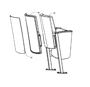
[0030] FIG. 5A is a rear perspective exploded view of FIG. 1.
[0031] FIG. 6 is a rear perspective view of FIG. I.
[0032] FIG. 6A is a section view of FIG. 1 through the middle of the
chair.
[0033] FIG. 7 is a front perspective view of FIG. 1 with the seat in the
up position.
[0034] FIG. 8 a front perspective view of FIG. 7.
[0035] FIG. 9 is a perspective view of a component of the chair in FIG.
1
[0036] FIG. 10 is a perspective view of another component of the chair
of FIG. 1
[0037] FIG. 11 is a perspective view of the right support of the chair of
FIG. I.
[0038] FIG. 12 is a perspective view of the left support of the chair of
FIG. 1.
Date Recue/Date Received 2022-09-14
- 9 -
[0039] FIG. 13 is a rear perspective view of the chair of FIG. 1 with
decorative pieces and foam removed from the back.
[0040] FIG. 14 is a detail view of FIG. 13.
p0411 FIG. 15 is a rear view of the chair of FIG. 1 in the upholstered
back configuration.
[0042] FIG. 16 shows an assembly process for the chair.
[0043] FIG. 17 shows a perspective view of an embodiment of the chair
according to the present invention with the seat cushion removed.
[0044] FIG. 18 shows a top view of FIG. 17.
[0045] FIG. 19 shows a perspective view of a component of the seat
bottom of FIG. 17.
[0046] FIG. 20 shows a detail perspective view of the seat bottom
support structure of FIG. 17.
DETAILED DESCRIPTION OF THE INVENTION
[0047] Referring now to the drawings, wherein like reference numerals
designate corresponding structure throughout the views. The following
examples are presented to further illustrate and explain the present invention
and should not be taken as limiting in any regard.
[0048] A chair according to the present invention is shown in FIG. 1 an
the following figures. The chair 1 includes a seat 6, a backrest 4 and a frame
including e.g. frame pieces 34/36 with legs 24 that bolt to a floor/riser or
other
fixed structure. The back cushion 9 and the seat cushion 7 are upholstered
foam and optional side panels 5 can be provided, depending on the aesthetic
requirements. FIG. 2 shows the chair of FIG. 1 but with the cushions 7/9
removed so that the interior support structure can be seen. The back support
12 provides a metal frame which is molded over in foam. The seat frame 10
Date Recue/Date Received 2022-09-14
- 10 -
is also molded over in foam with both the seat and backrest being further
upholstered. Rigid panel 8 is provided to secure to the seat and the seat
frame 10 to provide added protection and durability along with the desired
aesthetic.
[0049] FIG. 3 depicts the webbing 15 which wraps around metal frame
parts 14 across the seat. The webbing may also weave in with front to back
webbing 15'. It is understood that only some of the webbing is shown to avoid
drawing clutter. This arrangement can also be used for the backrest.
Additional details on the webbing and arrangement of the surround foam is
shown and described in U.S. 7,690,732. The front of the frame 10 includes a
polymeric part 16 which is preferably injection molded and secured with
fasteners 20 to the rigid panel 8. These fasteners insert into narrowing
openings in that a hole can be cut in the bottom of the foam/upholstery of the
seat and the fasteners inserted into the larger holes shown and then slid down
into position into the narrowed section. As a result, the fastener head is
retained in position but is not accessible from the upper surface of the seat
or
from the inner surface of the backrest (the upper and inner surfaces here
referring to those the user would sit on). In this manner, the rigid panel can
be secured to the seat in a discrete way such that the fasteners are not
visible
or may be considered blind fasteners. In certain aspects, the foam may be
molded with a lower void where the narrowing openings are located, for
example cylinder/oval shaped protrusions may extend from the bottom of the
mold to contact the plates 2002 or the holes 52 in order to inhibit foam from
closing these areas. As a result, the protrusion of the bottom rigid panel can
insert into that void easily, particularly the screw which may be considered
part of the protrusion. The upholstery cover may be designed to overlap the
lower perimeter of the seat by a small amount such as 0.5 to 1 inches, thus
leaving this void accessible to the screw for securing the rigid panel to the
bottom. A similar structure can be employed for the backrest and the
Date Recue/Date Received 2022-10-26
- 11 -
corresponding narrowing openings. Further support of the rigid panel may be
provided by the pin/pin support of the rotation mechanism inserting through a
hole in the rigid panel located at the rotation axis of the seat. As shown in
FIG. 15, fasteners and a plug covering the fastener can be used on the rear of
the panel 8 to secure the panel to the rear support 18 of the seat frame. FIG.
3 further depicts foam 17 which molds over the webbing 15/15'. Since the
foam and webbing or other flexible support provide both adequate support
and cushion, the seat can be thinner than slab foam seats. However, the
comfort of this design may sometimes rely on the ability for the lower surface
of the seat to deflect down. Slab foam arrangements generally prevent this
movement as a rigid wood support would not allow such deflection. In the
arrangement shown, the seat cushion is relatively thin compared to the space
provided by the rigid panel 8 and as a result, there is free space between the
lower/outer surface of the foam cushion and the upper/inner surface of the
rigid panel 8. This is free space is generally in the area of the two sided
black
arrow 600 in FIG. 6A. As a result of this free space, when the user sits on
the
seat, the lower surface of the foam cushion deflects downwards and is not
restricted by the rigid panel. Thus the comfort and softness of the seat is
controlled by the flexible support/webbing and the foam while still giving the
look of a rigid lower panel of the seat. As can be seen, some or all of the
foam cushion may rest inside the cavity defined by the interior of the rigid
panel 8.
[0050] Referring to FIG. 5, the rear of the seat is shown in exploded
view with the cushion removed. The plastic panel 4 is provided with an outer
or rear cavity that decorative panel 22 fits into. Typically glue will be used
for
securing. Although the fasteners 20 are shown connected to the frame 12, it is
understood that when assembling, typically the fasteners 20 will be threaded
into the posts/protrusions 32, a hole cut in the rear upholstery and the
fasteners inserted. As seen in FIG. 6, the decorative panel rests in the rear
cavity of the rigid panel 41 of the back. This decorative panel may be e.g.
Date Recue/Date Received 2022-09-14
- 12 -
wood veneer, wood look materials or a printed/sublimated/hydro dipped
panel. Other manners of decorating the panel can be used. Due to the
decorative panel 22 sitting within the rear cavity of the rigid panel 41, the
edges of the decorative panel 22 are protected. This is particularly useful
for
wood, plywood and especially thin materials as the edges could otherwise
become damaged. The normal solution to the problem of providing a wood
panel on the back and solving for edge damage is to use a relatively thick
sheet of wood/plywood. However, this is more expensive and carries with it
the downsides of slab foam previously described. It is also contemplated that
the panels 41/22 can be not be used in the chair, depending on what design is
preferable. In this manner, all the same parts used for constructing the chair
can be used, just the panels 41/22 are removed and the upholstered back is
then visible. This allows for multiple different aesthetic options for the
chair
without requiring separate inventory for upholstered back surface, plastic
back
surface or wood back surface options. This increases flexibility for the
customer but limits inventory/cost for the manufacturer. FIG. 5A shows how
the panels 41/22 can both be used, just panel 41 or no panels can be used
without different inventory of parts. If the panels 41/22 are not used, the
foam
cushion 21, specifically its upholstered rear side would be visible.
[0051] FIGS 7 and 8 show a similar assembly process for the back as
compared to FIGS. 5 and 6 as the back. Specifically, the foam is not shown
on the seat and polymer part 16 can be seen (and in further detail in FIG.
10).
The rigid panel 8 includes a cavity on the inside for the foam seat to sit in
along with an outer cavity that the decorative panel 24 can sit in (typically
glued in). The pin/pin support can extend into hole 13 to further secure the
panel 8 and the fasteners in the protrusions of the rigid panel 8 secure to
the
plastic support part 16.
[0052] FIG. 9 depicts the rear panel 41. Protrusions 32 extend from the
inner surface into the inner cavity. These protrusions 32 would also be
provided on the bottom rigid panel 8. The rear panel in FIG. 9 includes a wing
Date Recue/Date Received 2022-09-14
- 13 -
area 30 which allows for securing to plate 38 (FIG. 14). The holes 46 allow
the same bolt/bushing/fastener combination to be used regardless of if the
rear panel 41 is used or not. FIG. 10 shows the polymeric part with channels
26. These channels are preferably designed to snap over tubes 14 to create
the seat frame. Channels 27 may be provided for e.g. bands/ band clamps/
tie wraps to wrap around the interface between parts 14 and 16 to ensure the
seat frame remains assembled under load. The holes 52 are provided with
narrowing openings to retain the fastener head 20 and allow for insertion and
then sliding to secure. The polymeric part 16 is provided with supporting rib
28 structures to allow for adequate rigidity without requiring a solid piece
of
plastic in the front. The seat support design provides a structure that can be
assembled with less welding and/or tube bending or without welding and/or
tube bending, thus requiring less skilled labor to create the seat support.
This
allows for reduced cost of manufacture while maintaining overall quality.
[0053] FIG. 11 and 12 show the left and right components of the frame.
As can be seen, the outer surface 36 is provided without holes, but holes 34
are seen on the inner surface. When the back frame 12 is assembled via
plate 38, rivets 40 can feed into and are secured to this hole 34. The result
is
that the rear of the seat frame does not have visible fasteners on the upper
side. The back frame is also provided with tabs including narrowing openings
or catches to hold the fastener head in position. As stated earlier, the
fasteners can be inserted through holes cut in the rear of the foam/upholstery
of the seat/back to attach panels 8/41 as the case may be.
[0054] FIG. 16 shows an exemplary process by which the chair may be
manufactured. As shown, the seat/back support frame(s) are provided 100.
These frames are placed in the mold and foam is injected 102. The support
frames may include flexible supports extending across the frame perimeters
or more rigid supports and these become substantially surrounded/embedded
in the foam. It is understood that some portions may not be fully embedded
as a result of the injection molding, but the overwhelming majority will be
Date Recue/Date Received 2022-09-14
- 14 -
incased in foam. The molded frames are then removed and upholstery
covers added 104. Holes are cut in the cover and foam 106 near the
protrusions where the fasteners 20 secure. Alternately, the molding process
may include protrusions which extend into the mold to inhibit foam from
covering the narrowing holes/catches the fasteners 20 interact with. These
protrusions would extend from the rear surface to the height within the mold
of
these narrowing holes/catches. With these cut holes/provided holes, the
fasteners can be aligned 108 and slid to secure the rigid panel 8/41 to the
respective support frame 110. Optionally, the decorative panel is attached
112, e.g. by gluing and the seat and back are assembled to the support
frame. The seat may be assembled on site via a drop-in rotation mechanism
or other rotation mechanism. The back may also be assembled to the frame
on site. The rigid panel described herein is preferably made of thin injection
molded plastic, thus the thin nature of the design may make it somewhat
flexible, but the part would still be considered rigid because when secured to
the support frame, twisting becomes less prevalent and a relatively hard
surface is provided by the rigid panel in comparison to the softer foam
cushion. The rigidity may, for example, be considered to be provided by the
material used, e.g. HDPE, LDPE, Nylon or other polymeric/ polymeric
composite materials of relatively higher durometers.
[0055] Referring to FIGS. 17-20 an alternate arrangement of the seat
bottom support and panel is depicted. The seat bottom uses the same
cushion structure having the flexible webbing and surround/injection molded
foam as in prior designs discussed herein. The seat frame includes a
different front assembly and rear assembly. The rear assembly is a thicker
tube 2006 which provides a counter weight for the gravity lift seat. The front
assembly is shown as two bars 2000 with plates 2002 welded at spaced
locations between the tubes. These plates 2002 include the same narrowing
opening used to attach the seat bottom/back in other embodiments. The bars
2000 are optionally bolted or riveted 2004 to the side support tubes. The
front
Date Recue/Date Received 2022-09-14
- 15 -
bar/plate assembly replaces the polymeric part depicted in FIG. 10 in the
embodiment shown. The decorative panel shown in FIG. 19 is preferably
injection molded like the others shown and described herein. The panel
includes posts/protrusions 32' that have holes therein to receive fasteners to
secure the panel to the seat bottom as in other embodiments of the decorative
panels shown and described herein. The protrusion may be considered to
include the fastener (screw) as part thereof. The screw can be adjusted to
ensure the screw head fits into the narrowing opening provided by the seat.
[0056] A rear protrusion 2008 is also molded to the panel at the back
and adjacent to screw hole 2010. In this manner, positive engagement with
the rear of the seat can be made between the plastic of the panel and the
seat. Through hole 2012 receives the pin for the connection/tilt mechanism
which is used to allow the seat to pivot/rotate and also provides further
securing of the decorative panel to the seat cushion. In this manner, if the
panel is bumped or kicked, that force will largely be supported by the rear
protrusions 2008 as opposed to creating shear forces on the screw passing
through the screw hole 2010 and securing to the rear of the frame. The
decorative panel shown in FIG. 19 also includes the appropriate cavity/space
as found in other embodiments described herein. This allows the cushion to
deflect when sat on and preferably a lower perimeter of the seat sits at least
partially within the cavity with the cushioned portion of the seat protruding
from the top of the panel. The panel can include the outer recess for
receiving the decorative plate, for example wood veneer.
[0057] Although the invention has been described with reference to a
particular arrangement of parts, features and the like, these are not intended
to exhaust all possible arrangements or features, and indeed many other
modifications and variations will be ascertainable to those of skill in the
art.
Date Recue/Date Received 2022-09-14