Note: Descriptions are shown in the official language in which they were submitted.
WO 2021/231970
PCT/US2021/032619
COMMUNICATING WITH AND CONTROLLING LOAD CONTROL SYSTEMS
CROSS REFERENCE
100011 This application claims priority from U.S. Provisional
Patent Application No.
63/025,075, filed May 14, 2020, which is incorporated by reference in its
entirety herein.
BACKGROUND
100021 A user environment, such as a residence, an office
building, or a hotel for
example, may be configured to include various types of load control systems.
For example, a
lighting control system may be used to control the lighting loads in the user
environment. A
motorized window treatment control system may be used to control the natural
light provided to
the user environment. A heating, ventilating, and air conditioning (HVAC)
system may be used
to control the temperature in the user environment.
SUMMARY
100031 One or more computing device may be implemented in a load
control system to
perform communication with and control of load control devices. The load
control devices may
comprise lighting control devices capable of being controlled to lighting
intensity values and
having different color settings The one or more computing devices may display
a graphical user
interface that enables configuration of scenes for controlling zones of
lighting control devices
configured to control corresponding lighting loads.
100041 The graphical user interface may include a scene
identification interface that
comprises an indication of each of a plurality of scenes that may be
configured for an area of the
load control system. The graphical user interface may include a zone
identification interface that
identifies each of one or more zones with a corresponding lighting intensity
and color setting.
The graphical user interface may include a control interface that comprises a
lighting intensity
bar for configuring the lighting intensity and/or a palette for configuring
the color setting for at
least one of the one or more zones.
1
CA 03174192 2022- 9- 29
WO 2021/231970
PCT/US2021/032619
100051 The one or more computing devices may receive a selection
of a scene indicated
in the scene identification interface. In response to receiving the selection
of the scene, the one or
more computing devices may update the lighting intensity and the color setting
identified for
each of the one or more zones in the zone identification interface according
the selected scene.
The one or more computing devices may receive a selection of a zone identified
in the zone
identification interface. In response to receiving the selection of the zone,
the one or more
computing devices may update the lighting intensity bar and the palette with
the respective
lighting intensity setting and color setting that are stored in the selected
scene for the selected
zone.
100061 The one or more computing devices may receive change to at
least one of the
lighting intensity setting or the color setting via the control interface. A
change may be
configured to cause a change from a first lighting intensity setting to a
second lighting intensity
setting or a first color setting to a second color setting. The one or more
computing devices may
control the lighting intensity or the color setting of the corresponding
lighting load in the selected
zone to the second lighting intensity setting or the second color setting.
100071 The one or more computing devices may receive an
indication from a user to save
the change to the selected scene and update system configuration data to
control the selected
zone to the second lighting intensity setting or the second color setting in
response to an
activation of the selected scene. In response to receiving a triggering event
configured to trigger
the activation of the selected scene, the one or more zones may be controlled
according to the
updated system configuration data.
100081 The lighting intensity bar may be configured to display in
at least one of a first
and a second of a plurality of resolution states to enable different
resolutions of control for a
user. When the lighting intensity bar is displayed in the graphical user
interface in the first
resolution state, the one or more computing devices may receive a first input
from the user in the
lighting intensity bar that is configured to cause the lighting intensity to
change over a first range
of lighting intensity values from a current lighting intensity value to a
first lighting intensity
value The first input may cause a control indicator in the lighting intensity
bar to move by a
2
CA 03174192 2022- 9- 29
WO 2021/231970
PCT/US2021/032619
first distance on the graphical user interface to indicate the change in the
lighting intensity over
the first range of lighting intensity values.
100091 The one or more computing devices may receive an
indication to change the
lighting intensity bar from the first resolution state to the second
resolution state. When the
lighting intensity bar is displayed in the graphical user interface in the
second resolution state,
the one or more computing devices may receive a second input from the user in
the lighting
intensity bar. The second input may cause the lighting intensity to change
over a second range of
lighting intensity values from the first lighting intensity value to a second
lighting intensity
value. The second input may cause the control indicator in the lighting
intensity bar to move by
a second distance on the graphical user interface to indicate the change in
the lighting intensity
over the second range of lighting intensity values. The second distance over
which the control
indicator moves may be greater than or equal to the first distance. The second
range of lighting
intensity values may be less than the first range of lighting intensity values
over which the
lighting load is controlled.
BRIEF DESCRIPTION OF THE DRAWINGS
100101 The patent or application file contains at least one
drawing executed in color.
Copies of this patent or patent application publication with color drawing(s)
will be provided by
the Office upon request and payment of the necessary fee.
100111 Figure 1 is a system diagram that illustrates an example
load control system that
includes control-devices.
100121 Figure 2 is a block diagram of an example network device.
100131 Figures 3A and 3B are flowcharts depicting an example
procedure for configuring
and/or controlling a load control system.
100141 Figures 4A-4G show example graphical user interfaces of an
application that may
allow a user to determine scene information and to control a load control
system and/or one or
more load control devices
3
CA 03174192 2022- 9- 29
WO 2021/231970
PCT/US2021/032619
100151 Figures 5A-5Z show additional example graphical user
interfaces of an
application that may allow a user to determine scene information and to
control a load control
system and/or one or more load control devices.
100161 Figure 6 is a block diagram of an example system
controller.
100171 Figure 7 is a block diagram of an example control-target
device.
100181 Figure 8 is a block diagram of an example control-source
device.
DETAILED DESCRIPTION
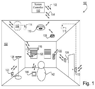
100191 Figure 1 shows a high-level diagram of an example load
control system 100.
Load control system 100 may include a system controller 150 and load control
devices for
controlling (e.g., directly and/or indirectly) one or more electrical loads in
a user environment
102 (also referred to herein as a load control environment). Example user
environments/load
control environments 102 may include one or more rooms of a home, one or more
floors of a
building, one or rooms of a hotel, etc. As an example, load control system 100
may enable the
automated control of lighting systems, shades, and heating, ventilating, and
air conditioning
(HVAC) systems in the user environment, among other electrical loads.
100201 The load control devices of load control system 100 may
include a system
controller 150, control-source devices (e.g., elements 108, 110, 120, and 122
discussed below),
and control-target devices (e.g., elements 112, 113, 116, 124, and 126
discussed below) (control-
source devices and control-target devices may be individually and/or
collectively referred to
herein as load control devices and/or control devices). The system controller
150, the control-
source devices, and the control-target devices may be configured to
communicate (transmit
and/or receive) messages, such as digital messages (although other types of
messages may be
communicated), between one another using wireless signals 154 (e.g., radio-
frequency (RF)
signals), although wired communications may also be used. "Digital" messages
will be used
herein for discussion purposes only.
100211 The control-source devices may include, for example, input
devices that are
configured to detect conditions within the user environment 102 (e.g., user
inputs via switches,
4
CA 03174192 2022- 9- 29
WO 2021/231970
PCT/US2021/032619
occupancy/vacancy conditions, changes in measured light intensities, and/or
other input
information) and in response to the detected conditions, transmit messages to
control-target
devices that are configured to control electrical loads in response to
instructions or commands
received in the messages. The control-target devices may include, for example,
load control
devices that are configured to receive messages from the control-source
devices and/or the
system controller 150 and to control respective electrical loads in response
to the received
messages. A single control device of the load control system 100 may operate
as both a control-
source device and a control-target device.
100221 According to one example, the system controller 150 may be
configured to
receive the messages transmitted by the control-source devices, to interpret
these messages based
on a configuration of the load control system, and to then transmit messages
to the control-target
devices for the control-target devices to then control respective electrical
loads. In other words,
the control-source devices and the control-target device may communicate via
the system
controller 150. According to another and/or additional example, the control-
source devices may
directly communicate with the control-target devices without the assistance of
the system
controller 150. The system controller may still monitor such communications.
According to a
further and/or additional example, the system controller 150 may originate and
then
communicate messages with control-source devices and/or control-target
devices. Such
communications by the system controller 150 may include
programming/configuration data (e.g.,
settings) for the control devices, such as configuring scene buttons on light
switches.
Communications from the system controller 150 may also include, for example,
messages
directed to control-target devices and that contain instructions or commands
for the control-target
devices to control respective electrical loads in response to the received
messages. For example,
the system controller 150 may communicate messages to change light levels, to
change shade
levels, to change HVAC settings, etc. These are examples and other examples
are possible.
100231 Communications between the system controller 150, the
control-source devices,
and the control-target devices may be via a wired and/or wireless
communications network as
indicated above. One example of a wireless communications network may be a
wireless LAN
where the system controller, control-source devices, and the control-target
devices may
communicate via a router, for example, that is local to the user environment
102. For example,
CA 03174192 2022- 9- 29
WO 2021/231970
PCT/US2021/032619
such a network may be a standard Wi-Fi network. Another example of a wireless
communications network may be a point-to-point communications network where
the system
controller, control-source devices, and the control-target devices communicate
directly with one
another using, for example, Bluetooth, Wi-Fi Direct, a proprietary
communication channel, such
as CLEAR CONNECIlm, etc. to directly communicate. Other network configurations
may be
used such as the system controller acting as an access point and providing one
or more
wireless/wired based networks through which the system controller, the control-
source devices,
and the control-target devices may communicate.
100241
For a control-target device to be responsive to messages from a control-
source
device, the control-source device may first need to be associated with the
control-target device.
As one example of an association procedure, a control-source device may be
associated with a
control-target device by a user 142 actuating a button on the control-source
device and/or the
control-target device. The actuation of the button on the control-source
device and/or the
control-target device may place the control-source device and/or the control-
target device in an
association mode for being associated with one another. In the association
mode, the control-
source device may transmit an association message(s) to the control-target
device (directly or
through the system controller). The association message from the control-
source device may
include a unique identifier of the control-source device. The control-target
device may locally
store the unique identifier of the control-source, such that the control-
target device may be
capable of recognizing messages (e.g., subsequent messages) from the control-
source device that
may include load control instructions or commands. The control-target device
may be
configured to respond to the messages from the associated control-source
device by controlling a
corresponding electrical load according to the load control instructions
received in the messages.
This is merely one example of how control devices may communicate and be
associated with
one another and other examples are possible. According to another example, the
system
controller 150 may receive configuration instructions from a user that specify
which control-
source devices should control which control-target devices. Thereafter, the
system controller
may communicate this configuration information to the control-source devices
and/or control-
target devices.
6
CA 03174192 2022- 9- 29
WO 2021/231970
PCT/US2021/032619
100251 As one example of a control-target device, load control
system 100 may include
one or more lighting control devices, such as the lighting control devices 112
and 113. The
lighting control device 112 may be a dimmer, an electronic switch, a ballast,
a light emitting
diode (LED) driver(s), and/or the like. The lighting control device 112 may be
configured to
directly control an amount of power provided to a lighting load(s), such as
lighting load 114.
The lighting control device 112 may be configured to wirelessly receive
messages via signals
154 (e.g., messages originating from a control-source device and/or the system
controller 150),
and to control the lighting load 114 in response to the received messages One
will recognize
that lighting control device 112 and lighting load 114 may be integral and
thus part of the same
fixture or may be separate.
100261 The lighting control device 113 may be a wall-mounted
dimmer, a wall-mounted
switch, or other keypad device for controlling a lighting load(s), such as
lighting load 115. The
lighting control device 113 may be adapted to be mounted in a standard
electrical wall box. The
lighting control device 113 may include one or more buttons for controlling
the lighting load
115. The lighting control device 113 may include a toggle actuator. Actuations
(e.g., successive
actuations) of the toggle actuator may toggle (e.g., turn off and on) the
lighting load 115. The
lighting control device 113 may include an intensity adjustment actuator
(e.g., a rocker switch or
intensity adjustment buttons). Actuations of an upper portion or a lower
portion of the intensity
adjustment actuator may respectively increase or decrease the amount of power
delivered to the
lighting load 115 and thus increase or decrease the intensity of the receptive
lighting load from a
minimum intensity (e.g., approximately 1%) to a maximum intensity (e.g.,
approximately 100%).
The lighting control device 113 may include a plurality (two or more) of
visual indicators, e.g.,
light-emitting diodes (LEDs), which may be arranged in a linear array and that
may illuminate to
provide feedback of the intensity of the lighting load 115.
100271 The lighting control device 113 may be configured to
wirelessly receive messages
via wireless signals 154 (e.g., messages originating from a control-source
device and/or the
system controller 150). The lighting control device 113 may be configured to
control the
lighting load 115 in response to the received messages.
7
CA 03174192 2022- 9- 29
WO 2021/231970
PCT/US2021/032619
100281 The load control system 100 may include one or more other
control-target
devices, such as a motorized window treatment 116 for directly controlling the
covering material
118 (e.g., via an electrical motor); ceiling fans; a table top or plug-in load
control device 126 for
directly controlling a floor lamp 128, a desk lamp, and/or other electrical
loads that may be
plugged into the plug-in load control device 126; and/or a temperature control
device 124 (e.g.,
thermostat) for directly controlling an HVAC system (not shown). The load
control system 100
may also, or alternatively, include an audio control device (e.g., a speaker
system) and/or a video
control device (e.g., a device capable of streaming video content). Again,
these devices may be
configured to wirelessly receive messages via wireless signals 154 (e.g.,
messages originating
from a control-source device and/or the system controller 150). These devices
may be configured
to control respective electrical loads in response to the received messages.
100291 Control-target devices, in addition to being configured to
wirelessly receive
messages via wireless signals and to control respective electrical loads in
response to the
received messages, may also be configured to wirelessly transmit messages via
wireless signals
(e.g., to the system controller 150 and/or an associated control device(s)). A
control-target
device may communicate such messages to confirm receipt of messages and
actions taken, to
report status (e.g., light levels), etc. Again, control-target devices may
also or alternatively
communicate via wired communications.
100301 With respect to control-source devices, the load control
system 100 may include
one or more remote-control devices 122, one or more occupancy sensors 110, one
or more
daylight sensors 108, and/or one or more window sensors 120. The control-
source devices may
wirelessly send or communicate messages via wireless signals, such as signals
154, to associated
control-target devices for controlling an electrical load. The remote-control
device 122 may send
messages for controlling one or more control-target devices after actuation of
one or more
buttons on the remote-control device 122. One or more buttons may correspond
to a preset scene
for controlling the lighting load 115, for example. The occupancy sensor 110
may send
messages to control-target devices in response to an occupancy and/or vacancy
condition (e.g.,
movement or lack of movement) that is sensed within its observable area. The
daylight sensor
108 may send messages to control-target devices in response to the detection
of an amount of
light within its observable area. The window sensor 120 may send messages to
control-target
8
CA 03174192 2022- 9- 29
WO 2021/231970
PCT/US2021/032619
devices in response to a measured level of light received from outside of the
user environment
102. For example, the window sensor 120 may detect when sunlight is directly
shining into the
window sensor 120, is reflected onto the window sensor 120, and/or is blocked
by external
means, such as clouds or a building. The window sensor 120 may send messages
indicating the
measured light level. The load control system 100 may include one or more
other control-source
devices. Again, one will recognize that control-source devices may also or
alternatively
communicate via wired communications.
100311 Turning again to the system controller 150, it may
facilitate the communication of
messages from control-source devices to associated control-target devices
and/or monitor such
messages as indicated above, thereby knowing when a control-source device
detects an event and
when a control-target device is changing the status/state of an electrical
load. It may
communicate programming/configuration information to the control devices. The
system
controller 150 may also be the source of control messages to control-target
devices, for example,
instructing the devices to control corresponding electrical loads. As one
example of the later, the
system controller may run one or more time-clock operations that automatically
communicates
messages to control-target devices based on configured schedules (e.g.,
commands to lighting
control device 113 to adjust light 115, commands to motorized window treatment
116 for
directly controlling the covering material 118, etc.) For description purposes
only, shades will
be used herein to describe functions and features related to motorized window
treatments.
Nonetheless, one will recognize that features and functions described herein
are applicable to
other types of window coverings such as drapes, curtains, blinds, etc. Other
examples are
possible.
100321 According to a further aspect of load control system 100,
the system controller
150 may be configured to communicate with one or more network devices 144 in
use by a
user(s) 142, for example. The network device 144 may include a personal
computer (PC), a
laptop, a tablet, a smart phone, or equivalent device. The system controller
150 and the network
device 144 may communicate via a wired and/or wireless communications network.
The
communications network may be the same network used by the system controller
and the control
devices, or may be a different network (e.g., a wireless communications
network using wireless
signals 152). As one example, the system controller 150 and the network device
144 may
9
CA 03174192 2022- 9- 29
WO 2021/231970
PCT/US2021/032619
communicate over a wireless LAN (e.g., that is local to the user environment
102). For example,
such a network may be a standard Wi-Fl network provided by a router local to
the user
environment 102. As another example, the system controller 150 and the network
device 144
may communicate directly with one-another using, for example, Bluetooth, Wi-Fl
Direct, etc.
Other examples are possible such as the system controller acting as an access
point and
providing one or more wireless/wired based networks through which the system
controller and
network device may communicate.
100331 In general, the system controller 150 may be configured to
allow a user 142 of the
network device 144 to determine, for example, the configuration of the user
environment 102
and load control system 100, such as rooms in the environment, which control
devices are in
which rooms (e.g., the location of the control devices within the user
environment, such as which
rooms), to determine the status and/or configuration of control devices (e.g.,
light levels, HVAC
levels, shade levels), to configure the system controller (e.g., to change
time clock schedules), to
issue commands to the system controller in order to control and/or configure
the control devices
(e.g., change light levels, change HVAC levels, change shade levels, change
presets, etc.), etc.
Other examples are possible.
100341 The load control system 100 of Figure 1 may be configured
such that the system
controller 150 is only capable of communicating with a network device 144 when
that device is
local to the system controller, in other words, for the two to directly
communicate in a point-to-
point fashion or through a local network specific to the user environment 102
(such as a network
provided by a router that is local to the user environment). It may be
advantageous to allow a
user of network device 144 to communicate with the system controller 150 and
to control the
load control system 100 from remote locations, such as via the Internet or
other public or private
network. Similarly, it may be advantageous to allow third-party integrators to
communicate with
the system controller 150 in order to provide enhanced services to users of
user environment 102.
For example, a third-party integrator may provide other systems within user
environment 102. It
may be beneficial to integrate such systems with load control system 100.
100351 Figure 2 shows an example block diagram of network device
280 (this diagram
may also apply to the network devices 144, a remote network device, or another
computing
CA 03174192 2022- 9- 29
WO 2021/231970
PCT/US2021/032619
device capable of network communications, for example). Network device 280 may
include one
or more general purpose processors, special purpose processors, conventional
processors, digital
signal processors (DSPs), microprocessors, microcontrollers, integrated
circuits, programmable
logic devices (PLD), application specific integrated circuits (ASICs), or the
like and/or may
further include other processing element(s) such as one or more graphic
processors (hereinafter
collectively referred to as control circuits(s) 202). Control circuit(s) 202
may control the
functionality of the network device and may execute the control/configuration
application 203, in
addition to other software applications such an operating system(s), database
management
systems, etc., to provide features and functions as describe herein. The
control circuit(s) 202
may also perform signal coding, data processing, power control, input/output
processing, and any
other functionality that enables the network device 280 to perform as
described herein. The
network device 280 may also include one or more memory 204 (including volatile
and non-
volatile memory) which may be non-removable memory and/or a removable memory.
100361 Memory 204 may be communicatively coupled to the control
circuit(s) 202. Non-
removable memory 204 may include random-access memory (RAM), read-only memory
(ROM), a hard disk(s), or any other type of non-removable memory storage.
Removable
memory 204 may include a subscriber identity module (SIM) card, a memory
stick, a memory
card, or any other type of removable memory. The one or more memory 204 may
store the
control/configuration application 203 and may also provide an execution space
as the
processor(s) execute the control/configuration application. Network device 280
may also include
a visual display screen(s)/terminal(s) 206 that may be communicatively coupled
to the control
circuit(s) 202. Together with control circuit(s) 202, visual display screen(s)
206 may display
information to the user via one or more GUI based interfaces/GUI based
"window(s)" as
described herein. The display screen(s) 206 and the control circuit(s) 202 may
be in two-way
communication, as the display screen 206 may include a touch sensitive visual
screen component
configured to receive information from a user and providing such information
to the control
circuit(s) 202
100371 Network device 280 may also include one or more
input/output (I/O) devices 212
(e.g., a keyboard, a touch sensitive pad, a mouse, a trackball, audio speaker,
audio receiver, etc.)
that may be communicatively coupled to the control circuit(s) 202. The I/O
devices may allow
11
CA 03174192 2022- 9- 29
WO 2021/231970
PCT/US2021/032619
the user to interact with the control/configuration application 203, for
example. Network device
280 may further include one or more transceivers/ communications circuits
(collectively,
communications circuit(s) 208) for communicating (transmitting and/or
receiving) over wired
and/or wireless communication networks, for example. The communications
circuit(s) 208 may
include an Itf transceiver(s) or other circuit(s) configured to perform
wireless communications
via an antenna(s). Communications circuit(s) 208 may be in communication with
control
circuit(s) 202 for transmitting and/or receiving information. Each of the
components within the
network device 280 may be powered by a power source 210. The power source 210
may include
an AC power supply and/or DC power supply, for example. The power source 210
may generate
a supply voltage(s) Vcc for powering the components within the network device
280.
100381 In addition to including GUI based software components,
for example, that
provide the graphical features and visual images described herein, the
control/configuration
application 203 may also include a logic engine(s) for providing features of
the GUI and features
of the application in general as described herein. The GUI based software
components and/or
logic engine may be one or more software based components that include
instructions, for
example, that are stored on and/or execute from one or more tangible memory
devices/components of the network device as indicated above. Features of the
control/configuration application may also and/or alternatively be provided by
firmware and/or
hardware in addition to/as an alternative to software based components. Again,
network device
280 is an example and the control/configuration application may execute on
other types of
computing devices.
100391 As indicted, network device 280 may be similar to the
network device 144 (e.g.,
including an external network device accessed via a cloud), as described
herein. Accordingly,
the control/configuration application may communicate with the other devices
of the user
environment (e.g., the system controller, control-source devices, control-
target devices etc.) via a
network local to the user environment (such as a Wi-Fi network). Nonetheless,
one will
recognize that the control/configuration application 203/network device 280
may communicate
with other devices using other communication systems and/or protocols, etc. In
addition, the
control/configuration application 203 is described herein as being a self-
contained application
that executes on the network device 280 and communicates messages with the
system controller,
12
CA 03174192 2022- 9- 29
WO 2021/231970
PCT/US2021/032619
for example. In other words, logic of the control/configuration application
and generated
graphics associated with the application are described herein as executing
from the network
device. Nonetheless, features and/or graphics of the control/configuration
application may be
implemented in other fashions, such as a web hosted application with the
network device
interfacing with the web hosted application using a local application (e.g., a
web browser or
other application) for providing features and functions as described herein.
As one example, the
system controller may function as the web host.
100401 In general, while a user environment may include control
devices that the
control/configuration application/network device 280 may interact with,
control, and/or
configure via a system controller (e.g., the system controller 150), the user
environment may also
include other types of control devices that may be, for example, Wi-Fi enabled
and/or internet of
things enabled control devices for example (e.g., devices that are configured
to communicate via
wireless and/or wired based networks, such as HomeKit). For description
purposes, such other
control devices (e.g., control devices to which the control/configuration
application and/or
network device 280 does not communicate with via the system controller) may be
referred to
herein as Wi-Fi enabled and/or HomeKit enabled control devices. Nonetheless,
one will
recognize that the features described herein are not limited to Wi-Fi enabled
and/or HomeKit
enabled control devices. Examples of such other control devices may include
lighting control
devices/bulbs, thermostats, fans, etc.
100411 Network device 280 and the Wi-Fi enabled control devices,
for example, may be
configured to directly communicate with each other without having to
communicate through a
system controller (e.g., if the network device is also HomeKit enabled),
and/or may
communicate via one or more cloud based servers, for example, again without
communicating
through the system controller. According to one aspect of the
control/configuration application
203 described herein, assuming the network device 280 is configured to
communicate with such
Wi-Fi enabled control devices (e.g., via HomeKit), for example, the
control/configuration
application may be configured to also interact with, control, and/or configure
these devices, in
addition to control devices. In so doing, the control/configuration
application may combine
within the graphical interfaces described herein information obtained from
such Wi-Fi enabled
13
CA 03174192 2022- 9- 29
WO 2021/231970
PCT/US2021/032619
devices, for example, and information obtained on control devices that are
controlled by the
system controller.
100421 The control/configuration application 203 may also provide
interfaces that allow a
user to control and/or configure both Wi-Fi enabled control devices, for
example, and control
devices that are controlled by the system controller. For ease of description,
the
control/configuration application 203 will be described herein as interacting
with control devices
of a load control system. Nonetheless, similar functionality as described
herein may also apply
to Wi-Fi enabled devices that may not be controlled via the system controller
and to which the
network device may directly and/or indirectly communicate. One will also
recognize that the
control/configuration application described herein may alternatively control
Wi-Fi enabled
devices, for example, with which the network device 280 is configured to
directly and/or
indirectly control/interact with. Again, one will further recognize that while
control/configuration application 203 is described herein in the context of a
load control system
and communication systems, the features and functions of the
control/configuration application
are applicable to other types of control devices, load control systems, and
communication
systems including for example, Wi-Fi enabled and/or HomeKit enabled systems
100431 As one example, the network device 280 may display to a
user via a visual display
screen 206 an icon associated with the control/configuration application 203.
The network
device 280 may detect the selection of the icon by the user (e.g., such as
detecting the using
touching the icon) and in response, may start (e.g., which may also be
referred to herein as
launching, running, executing, activating and/or invoking) the
control/configuration application
203. The control/configuration application may be started in other ways,
including the network
device being configured to automatically start the application upon being
reset and/or powered
on. In response to being started or launched, the control/configuration
application (in addition to
performing security/authentication procedures, for example) may communicate
one or more
messages to the system controller, for example, to obtain/request/query for
various information,
such as status/state and/or configuration information of the load control
system, and use this
information to initially generate and display to the user via the display
screen of the network
device 280 a graphical user interface. Again, at starting, for example, the
control/configuration
application may also communicate with Wi-Fi enabled devices, for example, the
network devices
14
CA 03174192 2022- 9- 29
WO 2021/231970
PCT/US2021/032619
have been configured to communicate with. Thereafter, the
control/configuration application
may continue to request and/or receive various information from the system
controller at various
times depending on what information the control/configuration application may
need to display
to the user and/or is being generated by the system controller. Again, the
control/configuration
application 203 may also communicate with Wi-fi enabled devices in a similar
fashion.
[0044] Upon receiving information requests from the
control/configuration application
203 (such as requests for status and configuration information), the system
controller may
respond by communicating with control devices and/or a database(s), for
example, to determine
and provide the requested information and respond to the control/configuration
application with
one or more response messages. In addition to determining status and
configuration of the load
control system, for example, the control/configuration application 203 may
also allow a user to
communicate messages to the system controller to modify, edit, or change the
configuration
and/or state of the load control system as further described herein. In
addition, the system
controller may also asynchronously provide status and configuration
information to the
control/configuration application (e.g., provide an indication of status/state
changes of control
devices without the control/configuration application querying for such
changes). The
control/configuration application may use this information to update various
graphical user
interfaces displayed to the user via the network device 280. Again, Wi-Fi
enabled devices and
the control/configuration application and/or network device may interact in
similar fashions.
[0045] Before turning to the various graphical user interfaces,
the control/configuration
application 203 may provide to a user, a description of example types of
information the
control/configuration application may request/receive and/or configure, for
example, to generate
interfaces is discussed. For example, as described herein, the
control/configuration application
may request/obtain this information from another device (e.g. system
controller and/or one more
control source devices). Also, or alternatively, the information may be
maintained or stored
locally (e.g., stored at the memory device(s) 204). In addition to receiving
this information, the
control/configuration application may also alter such information at the
system controller, as
described herein.
CA 03174192 2022- 9- 29
WO 2021/231970
PCT/US2021/032619
100461 The control/configuration application may request/obtain
information related to
the configuration and current state/status of a load control system from
another device in the load
control system, such as the system controller and/or one or more control
source devices (e.g., the
remote-control device 122). Also, or alternatively, the network device 280 may
itself store or
maintain the configuration and current state/status information (e.g. , or a
subset of the
configuration and current stat/status information), and the
control/configuration application 203
may request/obtain this information from the memory device(s) 204. Such
information may
include, for example, the specific control devices that are part of the load
control system
including an identifier that indicates the type of the control device The
specific control device
types may include, for example, one or more lighting control devices (also
referred to herein also
as lighting devices) that each directly controls one or more respective
electrical lighting
loads/lights, one or more temperature control devices (such as and hereinafter
also referred to as
a thermostat device(s)) that directly control respective HVAC systems, one or
more ceiling fan
devices (also referred to herein as fan devices) that each directly controls
one or more respective
fans (e.g., on, off, fan speed), one or more audio control devices (e.g., a
speaker system), and one
or more window shade devices that each directly controls positions or levels
of one or more
respective shades (One will recognize that while shade devices and shades are
discussed herein
as an example of motorized window treatments and window covering, other types
of motorized
window treatments and window coverings are possible such as drapes, curtains,
blinds, etc.).
100471 The control source devices may include one or more
keypads, such as wall-
mounted keypads, tabletop keypads, and/or remote-control/handheld keypads and
devices (e.g.,
remote-control device 122). As an example, a given keypad may include one or
more actuators
such as buttons (although other types of actuators are possible), and may be
configured to control
one or more control devices/electrical loads (e.g., lighting control
devices/lighting load(s),
HVAC system(s), shade(s), fan(s), and/or speaker(s), etc.). A keypad may
include different
types of actuators such as on/off actuators, raise lower actuators for lights
or shades, fan speed
actuators, scene actuators, etc. For example, a scene actuator may set one or
more control
devices/electrical loads controlled by the keypad to a pre-set configuration
(e.g., a scene, as
described herein).
16
CA 03174192 2022- 9- 29
WO 2021/231970
PCT/US2021/032619
100481 The configuration and current state/status information may
also include a location
indicator for each control device that may indicate a location of the device
within the user
environment and/or the location of the electrical loads the device controls.
This indicator may be
in the form of a location name (e.g., a text string) and/or an indicator that
may be translated into
a location name (e.g., a text string), although other mechanisms may be used.
For example,
assuming the user environment is a home, possible locations may include
standard locations like
"kitchen," "living room," "family room," "dining room," "master bedroom,"
"bedroom," "master
bathroom," "bathroom," "basement," "front porch," "office," "lobby,"
"conference room," etc.
Locations may also include sub-locations in a room like "basement ¨ sitting
area," "basement ¨
game area," basement ¨ work area," basement ¨ storage area," etc. Locations
may also include
user defined/customized locations like: "Mary's bedroom," "John's bedroom,"
etc. The location
of a control device may be programmed into the load control system (and stored
in database, for
example) by a user when installing the system within the user environment. One
will recognize
these are examples.
100491 For lighting control devices, the configuration and
current state/status information
may also include a type indicator that may indicate a type of a lighting
load(s) (also referred to
herein as a light(s)) controlled by the control device. A type of a lighting
load may include, for
example, the function/purpose of the lighting load within its defined location
and/or
indicate/suggest a specific location of the lighting load within its defined
location (e.g., ceiling
light vs floor lamp). A type indicator may be in the form of a name/function
(e.g., a text string)
and/or an indicator that may be translated into a name/function (e.g., a text
string), although
other mechanism may be used. As an example, assuming the user environment is a
home,
standard types may include ceiling or overhead light, chandelier, pendant(s),
table lamp(s), floor
lamp(s), sconce(s), sink light(s) (e.g., for a kitchen or bathroom), island
light(s) (e.g., for a
kitchen), closet light(s), accent lights, downlights, desk area lights, etc.
Types may also include
user defined/customized types. The type of lighting load may be programmed
into load control
system (and stored in a database, for example) by a user when installing the
system within the
user environment. One will recognize these are examples. Types may also apply
to other
control devices such as fans, shades, and keypads. Again, the type indicator
may provide an
indication of a specific function and or location within the device's defined
location. Other
17
CA 03174192 2022- 9- 29
WO 2021/231970
PCT/US2021/032619
example types may include "left shade," "right shade," "center shade," "wall
keypad," "tabletop
keypad," etc.
100501 As described herein, the current state/status information
may also include a
current status/state and/or configuration of one or more of the control
devices. For example, for
a lighting control device the status information may include whether the
respective lighting
load(s) are in an on or off state, and if in the on state whether it is a
dimmed state and possibly
further the dimming level, color setting, vibrancy setting, etc. The
control/configuration
application may allow the user to modify scenes and to create new scenes via
the network
device. For an occupancy sensor, the status information may include, for
example, whether the
sensor has detected an occupancy event/condition and/or is in an occupancy
state, has detected a
continued occupancy event/condition and/or is in a continued occupancy state,
and/or has
detected a vacancy condition and/or is in a vacancy state. Again, these are
examples and other
information is possible.
100511 As another example, a device in the load control system,
such as the system
controller and/or one or more control source devices, may maintain information
related to one or
more pre-programmed scenes that may be actuated by a user from an application,
such as the
control/configuration application 203 or a control source device, such as the
remote-control
device 122. A scene may include, for example, certain settings for one or more
lights, shades,
etc. The device may maintain respective scene configuration information in a
database. The
control/configuration application may request/obtain information related to
these pre-
programmed scenes and as further described below, thereafter allow the user,
via the network
device, to a select a given scene, resulting in the control/configuration
application instructing the
another device (e.g., the system controller and/or one more control source
devices) to configure
control devices according to the selected scene (e.g., set one more light
levels, fan speeds, shade
levels, etc.). As also described below, the control/configuration application
may allow a user to
modify the pre-programmed scenes maintained and to create and store new scenes
that may
subsequently be selected by the user. After the scenes are created and stored,
the scenes may be
assigned. For example, a scene may be assigned to one or more zones in the
load control system,
and enabled by, for example, pressing a certain button at a remote control
device.
18
CA 03174192 2022- 9- 29
WO 2021/231970
PCT/US2021/032619
100521 As a still further example, various time clock schedules
may be maintained where
a schedule may be, for example, a certain setting for one or more control
devices (e.g., lights,
shades, etc.) that the system controller or one more control-source devices
automatically
configure based on the schedule. For example, the system controller may
maintain respective
time clock schedules in a database and the status of these schedules, such as
whether a given
schedule is active, inactive, or disabled. The control/configuration
application may obtain
control information related to these time clock schedules and as further
described below,
thereafter allow the user via the network device to modify these schedules and
to create new
schedules.
100531 A load control system may be configured and/or controlled
according to one or
more defined scenes. Also, or alternatively, the load control system may be
further divided into
one or more areas or locations (e.g., depending on the size of the load
control system or user
environment), and each of the areas or locations within the load control
system may be
configured and/or control according to one or more scenes. The scenes may be
activated, for
example, in response to a button press at a control source device (e.g.,
remote control device
122), via a graphical user interface on a network device (e.g., the network
devices 144, 280),
and/or based on a time clock, as described herein.
100541 As described herein, the devices in a load control system
may be grouped or
organized together based on their respective location within the user
environment. For example,
the devices in a load control system may be grouped and/or organized based on
their respective
location in the user environment (e.g., the devices in a single room may be
organized or grouped
together). After the devices are grouped or organized based on their location
in the user
environment, the devices may also be assigned to a certain zone. For example,
the lighting
devices in a certain location of a user environment may be assigned to a zone
based on their
respective function (e.g., the lighting control devices that are intended to
emit light a certain
surface, such as desk, may be grouped or organized together in a "Desk Area"
zone).
100551 Grouping or organizing the devices in a load control
system based on their
location and then assigning them to a zone (e.g., based on their function) may
allow a user to
configure or control the devices within a load control system more
efficiently. For example, as
19
CA 03174192 2022- 9- 29
WO 2021/231970
PCT/US2021/032619
the number of device in the load control system increases, the settings that
may be configured by
the user may also increase. And without grouping or organizing the device into
a more
manageable subset of devices, the user may fail to accurately and efficiently
control the
increased number of devices in the load control system. Moreover, the
capabilities and, as a
result, the configurable settings of each of the devices may differ, further
increasing the
complexity of configuring or controlling the load control system. If, however,
the devices are
grouped by their respective location and then assigned to a zone (e.g., based
on their respective
function), the user may configure the devices in the load control system by
zone, which may
improve the accuracy and efficiency of configuring and controlling the load
control system.
100561 After the devices in a load control system are organized
and grouped by location
and subsequently assigned to a zone, a user may collectively configure or
control the devices that
are assigned to a given zone. Further, since the devices that are assigned to
a given zone based
on their respective function, the settings for devices in that zone (e.g.,
lighting intensity and/or
color) may be configured to be the same, which may improve the accuracy and
efficiency of
configuring and controlling the load control system.
100571 Figures 3A and 3B are flowcharts that illustrate example
procedures for
configuring or controlling a load control system. Referring first to Figure
3A, there is shown an
example procedure 300 for displaying and updating system configuration data
for a load control
system. The procedure 300 may be performed by a control/configuration
application, such as the
control/configuration application 203, and may enter at 301. For example, the
procedure 300
may enter in response to an indication from a user to update the system
configuration data (e.g.,
configuration and current state/status information) for a load control system
(e.g., via a network
devices, such as the network devices 144, 280). The procedure 300 may be
performed after the
devices in a load control system have been grouped or organized by their
respective location in a
user environment and subsequently assigned to zones. Also, or alternatively,
the procedure 300
may be performed prior to the devices in a load control system being grouped
or organized by
their respective location in a user environment and/or assigned to a zone,
which may be stored
and/or maintained in the system configuration data.
CA 03174192 2022- 9- 29
WO 2021/231970
PCT/US2021/032619
100581 At 302, the control/configuration application may retrieve
the system
configuration data for the load control system. For example, the system
configuration data may
indicate or otherwise describe the devices that are configured in the load
control system. The
system configuration data may include a unique identifier of the locations or
areas of the user
environment/load control system that the devices are organized or grouped by.
The system
configuration data may also include a unique identifier of the zones within
each of the locations
or areas that the devices are assigned to, and/or one or more defined scenes
for controlling the
devices assigned to the zones. The system configuration data may be retrieved
from a single
device (e.g., a system controller, such as the system controller 150), or
portions of the system
configuration data may be retrieved from multiple devices (e.g., a system
controller, network
device, one or more control source devices, and/or one or more control target
devices). The
system configuration data may also be obtained from devices external to the
load control system,
such as from cloud based system or other load control systems to which a given
load control
system is integrated with.
100591 After retrieving the system configuration data, the
control/configuration
application may display a representation of the system configuration data
(e.g., or a portion of
the system configuration data) at 304. For example, the control/configuration
application may
display a representation of a defined scene for controlling one or more zones
in an area of user
environment or load control system via a graphical user interface. In
addition, one or more
lighting control device configured to control a corresponding lighting load
may be assigned to
each of the one or more zones. The graphical user interface may display
various controls or
control interfaces based on the lighting control device/lighting loads
assigned to a given zone.
For example, the graphical user interface may display a lighting intensity
(e.g., via lighting
intensity bar) for each of the one or more zones in the defined scene and/or a
palette that
identifies a color setting for controlling each of the one or more zones in
the scene. The palette
may be configured to display colors at different color temperatures at which
the lighting control
devices/lighting loads are capable of being controlled to, or a full color
gamut of colors at which
the lighting control devices/lighting load are capable of being controlled to.
100601 At 306, the control/configuration application may receive
updates or changes to
the system configuration data, for example, from a user. As described herein,
changes to the
21
CA 03174192 2022- 9- 29
WO 2021/231970
PCT/US2021/032619
system configuration data may include changes or updates to the settings
(e.g., lighting intensity,
color, CCT, vibrancy, etc.) for a defined scene. Accordingly, the
control/configuration
application may receive changes or updates to the system configuration data
via the displayed
lighting intensity and/or palette. Figures 4A to 4G and Figures 5A to 5Z
illustrate example
graphical user interfaces that may be displayed by the control/configuration
application to
represent the system configuration data and/or receive updates to the system
configuration data.
100611 At 308, control/configuration application may determine
whether there are
additional updates to the system configuration data. If the
control/configuration application
determines that there are additional updates, the control/configuration
application may receive
the additional updates. If, however, the control/configuration application
determines that there
are no additional updates, the control/configuration may store or send (e.g.,
store the updated
configuration data locally or send the configuration data to another device,
such as a system
controller) the updated system configuration data at 310 and the procedure 300
may exit at 311.
For example, the control/configuration application may determine that there
are no additional
updates when the control/configuration application receives an indication from
a user that there
are not additional updates to the system configuration data (e.g., selecting a
"Save" or "Finished"
button, such as the "Save to Scene" button 438 described herein with respect
to Figure 4B).
100621 Referring now to Figure 3B, there is shown an example
procedure 350 for
controlling a load control system based on a system configuration data, which,
as described
herein, may be defined or updated using the procedure 300. The procedure 350
may be
performed by a single device. For example, the procedure 350 may be performed
by a system
controller, a lighting control device, a network device, or another control
device to perform
control using the system configuration data stored thereon. Also, or
alternatively, the procedure
350 may be performed by multiple devices (e.g., a portion of the procedure 350
may be
performed by a first load control device and another portion of the procedure
350 may be
performed by a second load control device). For example, the system controller
may retrieve the
system configuration data (e.g., either locally or from another device) and
perform control based
on the system configuration data (e.g., by transmitting one or more message
that include control
instructions to perform control based to one or more lighting control devices
based on the system
configuration data).
22
CA 03174192 2022- 9- 29
WO 2021/231970
PCT/US2021/032619
100631 As illustrated in Figure 3B, the procedure 350 may be
performed in response to
the detection of a triggering event at 351. A triggering event may be an event
that causes the
devices in a load control system to be controlled according to the system
configuration data. For
example, as described herein, a triggering event may be caused by a user
actuation for activating
a scene (e.g. , by pressing a button that corresponds to a scene at a remote
control device); a
scheduled event (e.g., based on a time clock); and/or a sensor event (e.g., an
occupancy sensor
detecting occupancy). Accordingly, the system configuration data may be
retrieved at 352. As
described herein, the system configuration data may be stored at a system
controller and/or
across one or more other devices (e.g., remote-devices, network devices,
lighting control devices,
other control devices, etc.). Therefore, the system configuration data may be
retrieved from a
system controller and/or from one or other devices in the load control system.
After retrieving
the system configuration data, control may be performed based on the system
configuration data
at 354. For example, control may be performed by transmitting one or more
messages that
include control instructions to the load control device(s) based on the system
configuration data.
In another example, the control instructions may be stored locally thereon for
performing control
of the electrical load via the load control device. The procedure 350 may exit
at 355.
100641 Turning now to Figures 4A-5Z they illustrate example
graphical user interfaces of
control/configuration applications that may be executed at least in part on a
network device, such
as the control/configuration application 203 of the network device 280, for
configuring or
controlling a load control system. For example, Figures 4A-4G and Figures 5A-
5Z may
illustrate graphical user interfaces that may be displayed by the
control/configuration application
to display and/or update the system configuration data for a load control
system. Again, the
network device may be similar to the network devices 144, 280 as described
herein and may be a
personal computer (PC), a laptop, a tablet, a smart phone, or equivalent
device, for example,
although it may also be another type of computing device. The
control/configuration application
may be a graphical user interface (GUI) based application that may provide a
GUI based
interface/GUI based "window(s)" to a user via the network device and may allow
a user of the
network device to interact with, control, and/or configure control devices
within a user
environment (e.g., user environment 102) or load control system (e.g., the
load control system
100). For description purposes only, the load control system 100 of user
environment 102 and
23
CA 03174192 2022- 9- 29
WO 2021/231970
PCT/US2021/032619
the communication systems described with respect to Figure 1 will be used
herein as an example
load control system and communication system to describe the
control/configuration application.
Nonetheless, the features and functions of the control/configuration
application described herein
are applicable to other types of control devices, load control systems, and
communication
systems. As an example, the user environment 102 may be a residence or home
and the user of
the network device may be a resident of the home. Nonetheless, the example
control/configuration application may also be applicable to other types of
user environments,
such as a building, hotel, etc. and the user of the network device may be a
system administrator.
[0065] Figures 4A to 4G and Figures 5A to 5Z show example
graphical user interfaces
that may be displayed by a control/configuration application. The graphical
user interfaces may
provide for the control of one or more lighting control devices, for example,
by defining one or
more scenes. In addition, the lighting loads may be located at a residential
home or commercial
space. Accordingly, the graphical user interfaces of Figures 4A to 4F may be
used to control or
configure the control devices in a space. Referring now to Figure 4A, there is
shown a graphical
user interface 410 that may be displayed by the control/configuration
application. The graphical
user interface 410 may be displayed to a user via the network device 280, for
example. The
graphical user interface 410 may be similar to the other graphical user
interfaces described herein
(e.g., the graphical user interface 500 etc.). Although Figure 4A illustrates
one type of example
graphical user interface that may be displayed to provide configuration or
control, other types of
graphical user interfaces may also be used to control or configure the control
devices in a space.
[0066] The graphical user interface 410 may include a number of
tiles 411, 413, 415,
417, 419, 421, 423. Each of tiles 411, 413, 415, 417, 419, 421, 423 may convey
information to
the user and/or allow for user-selection for providing additional information
and/or
configuration. Each of the tiles 411, 413, 415, 417, 419, 421, 423 may provide
information
about devices in a preselected area within a floor of a building An energy
tile 411 may indicate
an amount of energy usage and/or savings. An alerts tile 413 may provide
alerts about devices in
the system. A schedules tile 415 may provide information about scheduled
events to the user
and/or allow a user to schedule events in the system. For example, after
selection of the
schedules tile 415, the user may configure lighting schedules for controlling
lighting control
devices in the system. A lights tile 417 may provide information about current
lighting
24
CA 03174192 2022- 9- 29
WO 2021/231970
PCT/US2021/032619
configurations in the system and/or allow a user to configure control of
lighting control devices
and/or lighting loads within the system. A shades tile 419 may provide
information about current
shade configurations in the system and/or allow a user to configure control of
shades within the
system. An occupancy tile 421 may provide information about current occupancy
conditions in
the system and/or allow a user to configure control of devices within the
system in response to
occupancy and/or vacancy events/conditions. A devices tile 423 may allow a
user to manage and
perform maintenance of devices.
[0067] A scene indicator 412 may be displayed in the lights tile
417. The scene indicator
412 may be an indication of the scene set for one or more lighting control
devices of the
preselected area (e.g., the "Bright" scene as shown in Figure 4A). The scene
indicator 412 may
be selectable or configurable, and/or may allow the user to select or define
the scene for one or
more lighting control devices (e.g., the one or more lighting control devices
in the preselected
area). After selecting the scene indictor 412, the control application may
display a graphical user
interface that provides a user with the ability to configure the settings
(e.g., static settings) for a
scene. As an example, after selecting the scene indicator 412, the
control/configuration
application may display the graphical user interface 410a to configure the
static settings for a
scene, as described herein with respect to Figures 4B to 4G. As another
example, the
control/configuration application may also, or alternatively, display the
graphical user interface
500 to configure the static settings for a scene, as described herein with
respect to Figures 5A to
5Z.
[0068] Turning now for Figure 4B, there is shown an example of
the graphical user
interface 410a that may be displayed by the control/configuration application
to control the
lighting intensity defined for scenes (e.g., after selection of the scene
indicator 412). The
graphical user interface 410a may be provided for configuring scenes in
response to the scene
indicator 412 (shown in Figure 4A), for example. The graphical user interface
410a may include
scene icons 414. The scene icons 414 may indicate the scenes that are defined
for the particular
area of the load control system. For example, referring to Figure 4B, the
defined scenes may
include: "Bright," "Cleaning," "Event," "Relax," and "Off." As described
herein, the scenes
CA 03174192 2022- 9- 29
WO 2021/231970
PCT/US2021/032619
defined for the area of the load control system may be stored and/or
maintained at the system
controller. Further, when a scene is selected, the system controller may
transmit one or more
messages that include control instructions to control the loads as defined by
the scene. In
addition, the scenes defined for the area of the load control system may be
selected via the
graphical user interface 410a. rt he scenes (e.g., and their respective
configurations) may be
communicated to a system controller. In response, the scenes may be activated
by the system
controller. Each of the scenes may be separately configurable and/or
programmable via the
graphical user interlace 410a. Further, the scene that is presently being
configured/programmed
and is active may be indicated by being highlighted. For example, referring to
Figure 4B, the
"Bright" scene may be that scene that is presently being configured/activated.
100691 After configuration, a scene may be activated via a
graphical user interface, such
as the graphical user interface 410a, or a control device, such as the remote-
control device 122.
For example, as described herein, the remote-control device 122 shown in FIG.
1 may include
one or more buttons, each of which may correspond to a configured scene of
FIG. 4B. The scene
may then be activated by actuating (e.g., pressing) the button on a graphical
user interface or
control device (e.g., remote control device) that corresponds to that scene.
Upon activation, the
configurations defined for the scene may be retrieved. For example, the
configurations may be
stored and retrieved from the graphical user interface, the control device,
and/or a system
controller, such as the system controller 150. Also, or alternatively, the
configurations for the
scene, or portions thereof, may be stored at and/or retrieved from multiple
devices. For example,
part of the configuration for a scene may be stored and retrieved from the
system controller, and
another part of the configuration for the scene may be stored at and/or
retrieved from the control
device. After the configuration for the scene has been retrieved, one or more
messages including
control instructions may be transmitted to control one or more load control
devices based on the
configuration of the scene.
100701 The lighting control devices configured for being
controlled in a given scene may
be organized into one or more zones. Referring to Figure 4B, the "Bright"
scene may include a
"Front Downlight" zone, a "Desk Area" 1 zone, a "Desk Area 2" zone, a "Desk
Area 3" zone,
and a "Hallway- zone. Each of the zones may be separately controllable via a
respective control
26
CA 03174192 2022- 9- 29
WO 2021/231970
PCT/US2021/032619
interface. For example, the "Desk Area 1" zone may be controlled by the
control interface 418
and the "Hallway" zone may be controlled by control interface 430.
100711 The control interface of a respective zone may vary based
on the load control
device associated with the zone. For example, referring to Figure 4B, the load
control device
associated with the "Desk Area 1" zone may be a dimmer. Accordingly, control
interface 418
may include an indicator 432, control line 436, and/or actuators 422, 420a,
420b. The indicator
432 may indicate the configured lighting intensity for the -Desk Area 1" zone
(e.g., 50% as
shown in Figure 4B). As described herein, the actuator 422 may be actuated
along the control
line 436 to control the lighting intensity of the "Desk Area 1" zone.
Similarly, actuator 420a may
be actuated to decrease the lighting intensity of the "Desk Area 1" zone and
actuator 420b may
be actuated to increase the lighting intensity of "Desk Area 1" zone Though
described herein as
a control line 436, the control line 436 may be another type of control
indicator or actuator
configured to control and/or indicate the lighting intensity value.
100721 The load control device associated with the "Hallway- zone
may be an electrical
switch. Accordingly, the graphical user interface 410a may include control
interface 430 to
control the lighting intensity of the "Hallway" zone. Control interface 430
may include an
indictor 434 to indicate the state of the Hallway zone and an actuator 424 to
control the state on
the "Hallway" zone. For example, referring to Figure 4B, the "Hallway" zone
may be set to On
or Off.
100731 The lighting intensities of the respective zones in a
scene may be uniformly
controlled. Accordingly, the graphical user interface 410a may include master
control actuators
416a, 416b. The master control actuators 416a, 416b may be used to uniformly
increase and/or
decrease the lighting intensities of each of the zones. Referring now to
Figure 4B, master control
actuator 416a may be actuated to uniformly decrease the lighting intensity
(e.g., or brightness) of
each of the zones and master control actuator 416b may be actuated to
uniformly increase the
lighting intensity of each of the zones. In addition, the actuators 416a, 416b
may respectively
increase and decrease the lighting intensity of each of the zones by a
relative amount to a current
lighting intensity setting (e.g., respectively increase or decrease the
lighting intensity of each of
the zones by 1%).
27
CA 03174192 2022- 9- 29
WO 2021/231970
PCT/US2021/032619
100741 Two or more zones may similarly be associated with one
another for common
color and/or intensity control. For example, the "Desk Area 1" zone and the
"Front Downlights"
zone may be associated with one another for common control. Each zone may be
controlled by
the master control actuators 416a, 416b, or through control of one of the
zones. The graphical
user interface 410a may include an indicator, such as a lock symbol or other
indicator, to indicate
each of the zones being collectively controlled.
100751 The graphical user interface 410a may include a rename
light and scenes button
426. The rename light and scenes button 426 may be actuated to adjust the name
of the lights
and/or scenes defined for the area of the load control system. The graphical
user interface 410a
may include a save scene button 438, which, when actuated may save the
configuration of and/or
changes to a respective scene.
100761 The graphical user interface 410a may include a "Live
Changes Enabled" actuator
428. When the Live Changes Enabled actuator 428 is enabled (e.g., as show in
Figure 4B), the
lighting controls that are defined by the user via the graphical user
interface 410a may be present
at the respective lighting control devices in the load control system. For
example, control
instructions that indicate the defined lighting intensities may be transmitted
to the respective
lighting control devices, and the lighting control devices may transition to
indicate the lighting
intensities. In response, the user may be provided with live and real-time
feedback of the defined
lighting intensities. When the "Live Changes Enabled" actuator 428 is
disabled, the lighting
controls may be defined by the user via the graphical user interface 410a and
may be saved for
being implemented in the defined zones in the area when the defined scene is
triggered (e.g., via
occupancy event/condition, actuation of a button, a scheduling event, etc.).
100771 A scene may define the intensity and/or correlated color
temperature of a
respective zone, assuming the lighting loads are configured to emit colored
light. Turning now to
Figure 4C, the graphical user interface 410a may be displayed by the
control/configuration
application to control the warm or cool color temperatures defined by a zone.
As shown in in
Figure 4C, when a respective scene further defines a color temperature, the
scene indicators 414
may be highlighted with the color temperature defined for the scene (not
shown). The graphical
user interface 410a may include a master color control box 416c. The master
color control box
28
CA 03174192 2022- 9- 29
WO 2021/231970
PCT/US2021/032619
416c may be used by the user to uniformly control the color temperature
defined for each of the
zones in a scene. For example, referring to Figure 4C, the color temperature
defined for each of
the zones in the Bright scene may be set to 4500 K. When the color temperature
is set to different
colors for one or more of the zones for the area, the master color control box
416c may be set to
a default or null value. A value may be entered into the master color control
box 416c to
automatically conform the color temperatures in each of the zones.
100781 The graphical user interface 410a may include a control
interface 440 to control
the lighting intensity and color temperature defined for a zone (e.g., the
"Desk Area" zone as
shown in Figure 4C). The control interface 440 may include an indicator 442, a
"warm/cool"
actuator 446, a palette 448, an actuator 444, and/or a control line 450. The
palette 448 may show
a range of colors ranging from cool colors 443a at the top of the palette 448
to warm colors 443b
at the bottom of the palette 448. As described herein, these colors may
correspond to colors that
lie along the black body curve. For example, the palette 448 may show colors
along a range of
correlated color temperatures (CCTs) ranging from "warm white" (e.g., roughly
2600 K-3700 K)
at 443b, to "neutral white" (e.g., 3700 K-5000 K) to "cool white" (e.g., 5000
K-8300 K) at 443a.
The actuator 444 may be superimposed over the palette 448. The actuator 424
may be
movable/slide-able (e.g., here vertically movable) along the control line 450
to select different
CCTs along the black body curve.
100791 The control interface 440 may include similar indicators
and/or controls for
controlling the intensity of the lighting control devices as illustrated in
the control interface 418
shown in Figure 4B. For example, the control interface 440 may include an
indicator 432,
control line 436, and/or actuators 422, 420a, 420b. The control interface 440
may allow the user
to control the intensity and color temperature of lighting control devices in
the defined zone.
100801 A scene may provide for full color control of a respective
zone. Turning now to
Figure 4D, the graphical user interface 410a may be displayed by the
control/configuration
application to control the full color defined by a zone. The graphical user
interface 410a may
include a control interface 452 to control the lighting intensity and full
color for a zone (e.g., the
"Front Downlights" zone as shown in Figure 4D). The control interface 452 may
include control
line 436 and actuators 422, 420a, 420b to control the lighting intensity of
the "Front Downlight"
29
CA 03174192 2022- 9- 29
WO 2021/231970
PCT/US2021/032619
zone. The control interface 452 may include a palette 454 showing a plurality
of colors that lie
within the color gamut formed by the various RGBW LEDs, for example, that make
up the one
or more lighting loads in the defined zone.
100811 The one or more lighting loads in the defined zone may be
controlled to provide
full color and/or the warm/cool colors on the black body curve. The control
interface 452 may
include a warm/cool color tab 421a and full color tab 421b. Selection of the
warm/cool color tab
421a may display a palette in the control interface 452 that is similar to the
palette 448 shown in
the control interface 440 for the "Desk Area" zone to allow the user to define
warm/cool color
temperatures for the lighting control devices in the "Front Downlights" zone.
Selection of the
full color tab 421b may display the palette 454 that provides colors available
for full color
control.
100821 The user may select a location within the color palette
454 to define a color for
the corresponding zone. The color palette 454 is displayed such that different
color bands are
displayed from top to bottom (e.g., red, yellow, green, teal, blue, purple,
etc.). The color palette
454 is displayed such that a user may select the x-y coordinates on an x-axis
and a y-axis
corresponding to a given color. The color palette 454 may include white colors
on the far-right
side of the color palette 454, though the white colors may be located in other
areas of the color
palette 454.
100831 Turning now to Figure 4E, the control interface may
identify a user selection on
the color palette 454. Superimposed over the palette 454 may be an actuator
458 that identifies a
user selection within the color palette 454. The actuator 458 may be
movable/slide-able by the
user to any of a plurality of locations/colors within palette 454. The
graphical user interface
410a may display together with actuator 458 two perpendicular control lines
that intersect at the
center of the actuator 458. These control lines and the intersection point may
move with the
actuator 458 as it is moved by a user within palette 454, or as the user
selects another location
within the palette 454 independently. These control lines may assist the user
in moving actuator
458 either horizontally or vertically. Accordingly, actuator 458 may allow a
user to configure
the zone such that the zone produces colored light at a color point that lies
within the color gamut
CA 03174192 2022- 9- 29
WO 2021/231970
PCT/US2021/032619
formed by the various RGBW LEDs, e.g., that make up the one or more lighting
loads of the
defined zone.
100841 The color gamut formed by the various RGBW LEDs that make
up the lighting
load may be referenced using an x-y coordinate system. Accordingly, the
control interface 452
may include a coordinate indicator 456. The coordinate indicator 456 may
illustrate the x-y
coordinates of the selected color. For example, referring to Figure 4E, the
color selected for the
-Front Downlights" zone may be indicated by the x-y coordinates [0.123, 0.455]
indicating a
value on the x-axis and the y-axis.
100851 Upon the full color tab 421b being actuated by a user from
control interface 452,
or prior to the color being defined for the zone, the control/configuration
application may
initially display control interface 452 without actuator 458 and without the
control lines, as
shown in Figure 4D. Upon the user performing a selection within the palette
454, the graphical
user interface 410a may display actuator 458 and the control lines at a
relative point within
palette 454 to indicate the color being defined and/or produced by the one or
more lighting loads
within the zone.
100861 The graphical user interface 410a may include a "Show
Advanced Options"
button 460, which, when actuated may cause the graphical user interface 410a
to display
advanced options for control of a scene. Figure 4F shows an example of the
graphical user
interface 410a displaying advanced options for control of a scene. As shown in
Figure 4F, the
graphical user interface 410a may include an Include box 462, Fade time box
464, Delay time
box 466, and/or Vibrancy selector 468 for each of the respective zones in the
area. When the
Include box 462 is selected, the respective zone may be included in the scene.
For example,
referring to Figure 4F, the -Front Downlights" and -Desk Area . . ." zones may
be included in
the Bright scene.
100871 Fade time box 464 may be used by the user to select the
fade time of a zone when
the selected scene is implemented. The fade time may be the period of time
over which a
respective zone is to transition to the lighting intensity and/or color
temperature and/or color
defined by a scene. For example, referring to Figure 4F, the Front Downlights
zone may
transition, at the time the Bright scene is implemented, from a current
lighting intensity to a 50%
31
CA 03174192 2022- 9- 29
WO 2021/231970
PCT/US2021/032619
lighting intensity and from a current color temperature/color to a color
temperature of 4500K
over a period of 2 seconds. Similarly, the Delay time box 466 may be used by
the user to select
the delay time of a zone when the selected scene is implemented. The delay
time may include the
period of time during which a respective zone delays the transition indicated
by the scene. For
example, referring to Figure 4F, at the time the Bright scene is implemented
the -Front
Downlights" zone may delay the transition to a 50% lighting intensity and a
color temperature of
4500K for 2 seconds. The delay may be implemented prior to the fade time.
Accordingly, upon
a user implementing the Bright scene, the "Front Downlights" may wait 2
seconds before
transitioning from a current intensity and color temperature/color to a 50%
lighting intensity and
a color temperature of 4500K over a 2 second period of time.
100881 The graphical user interface may include a "Vibrancy"
selector 468. The
Vibrancy selector 468 may be used by the user to select the vibrancy for a
particular zone within
a scene. For example, the vibrancy may adjust the wavelength of the light
emitted by the zone,
which may affect the color of the light (e.g., the reflected light) on objects
within the zone. The
increased/decreased vibrancy may increase/decrease saturation of the color of
objects in the area
without changing the color of the light when the user looks at the light
(e.g., the color of the
emitted light). The Vibrancy selector 468 may allow the user to select a
relative level of
vibrancy (e.g., between zero and one-hundred percent) for
increasing/decreasing the vibrancy of
the one or more lighting loads for a defined zone. Changing the relative level
of vibrancy may
include decreasing or increasing the intensity of one or more white LEDs that
make up the one or
more lighting loads for a defined zone, thereby increasing or decreasing
vibrancy, respectively.
Changing vibrancy in this manner may also include changing the intensities of
other LEDs (e.g.,
red, green, and/or blue LEDs) of the loads in the zone to maintain the same
color output of the
lighting loads (e.g., to maintain the same (or approximately the same)
chromaticity coordinates
of the mixed color output of the lighting loads in the zone). Vibrancy
selector 468 may be
referred to as an adjustable vibrancy mode.
100891 The user may select the information button 469 to obtain
information about how
the vibrancy may be selected for a zone. Figure 4G is an example display 474
that may be shown
if the user selects the information button 469. The vibrancy may be changed
for each of the
zones that are configured for control along the black body curve. The vibrancy
may be enabled
32
CA 03174192 2022- 9- 29
WO 2021/231970
PCT/US2021/032619
for zones that are defined for control using the warm/cool color temperature
palette. The
vibrancy may be controlled for lighting control devices in a zone that are
being controlled along
the black body curve, as the lighting control devices may be using a number of
colored LEDs to
generate the color temperatures that are generated along the black body curve,
while also
allowing variation in the use of different LEDs to increase the color being
reflected to saturate
the colors in the area (e.g., by reducing the intensities of the white LEDs).
For zones that are
being controlled using full color, the vibrancy control may be limited to
colors that are within a
predefined range of the colors. For example, referring to the color palette
454 shown in Figure
4D and 4E, the vibrancy control may be limited to a predefined set of colors
on the right side of
the palette 454 indicated in Figure 4G. The predefined colors may be the 10%
or 20% of colors
on the right side of the palette. Vibrancy control may be disabled when the
user selects colors in
the palette that are outside of this predefined set of colors, as it may not
be possible to render
these colors in multiple ways using, for example, different intensities of RGB
and white LEDs.
100901 Referring again to Figure 4F, the graphical user interface
410a may control the
lighting intensity of different zones or lighting control devices separately,
while controlling the
color temperature in uniform. For example, the graphical user interface 410a
may include control
interfaces 470a, 470b to control the lighting intensities of two or more zones
(e.g., "Desk Area 1"
and "Desk Area 2") separately and control interface 472 to control the color
temperature of the
two or more zones in uniform. The control interfaces 470a, 470b may each
include an indicator
432, a control line 436 and actuators 422, 420a, 420b to separately control
the lighting intensity
of their respective zones or lighting control devices. Similarly, the control
interface 472 may
include an indicator 442, a palette 448, an actuator 444, and/or a control
line 450 to uniformly
control the color temperature of the zones. Though control interface 472
includes a warm/cool
color palette 448 for setting a color temperature along the black body curve,
full color control
may similarly be implemented.
100911 Referring now to Figure 5A, there is shown another example
graphical user
interface 500 that may be displayed by the control/configuration application
to a user via a
network device. The user may use the graphical user interface 500 to configure
and/or control
one or more lighting control devices, which may each be assigned to a
respective zone. The
graphical user interface 500 may be displayed to enable selection of an area
indicator 412a that
33
CA 03174192 2022- 9- 29
WO 2021/231970
PCT/US2021/032619
defines an area within which one or more scenes are defined. The area
indicator 412a may be
selected to edit or define predefined scenes within the area. A user may
interact with the
graphical interface 500 to configure/define a given scene in an area. For
example, the graphical
user interface 500 may display a list of areas and/or sub-areas in the load
control system that may
be configured. As shown in Figure 5A, for example, the list of areas that may
be configure
include: "Lobby," "Open Office," "Conference Room A," "Executive Office," and
"Open
Office." These areas may be sub-areas of a larger area, such as a floor in a
building (e.g., "Floor
1") and/or a portion of a floor (e.g., "North Wing," "South Wing", etc.).
After selecting the area
to configure by selecting the corresponding area indicator, the graphical user
interface 500 may
display scenes that may be further configured/defined for that area.
100921 After selection of a defined area, the
control/configuration information may
access the zones in the configuration information that are defined for the
selected area and enable
control/configuration of the zones in the area. For example, as shown in
Figure 5A, the user may
have selected to configure the "Lobby" area by selecting the area indicator
412a shown in Figure
5A, which may cause the graphical user interface to display the scene icons
504a, 504b, 504c,
504d, shown in Figure 5B, that may each be respectively configured via
graphical user interface
500.
100931 As shown in Figure 5B, the graphical user interface 500
may be used to configure
and store the intensity and/or color settings for one or more lighting control
devices for a
corresponding scene in the selected area. The graphical user interface 500
shown in Figure 5B
may include a scene identification interface 519. The scene identification
interface 519 may
include an indication of each of the plurality of scenes defined for the
selected area. For example,
the scene identification interface 519 may include one or more scene icons
504a, 504b, 504c,
504d, which may be examples of similar scene icons 414 described herein. As
described herein,
the scene icons 504a, 504b, 504c, 504d may indicate the scenes that are
defined for the particular
area of the load control system. For example, the scene icons 504a, 504b,
504c, 504d may
correspond to respective buttons on a remote control device or keypad in the
selected area. When
the button on a graphical user interface or a device (e.g., remote control
device) that corresponds
to a given scene is selected, the remote control device or a system controller
may transmit one or
messages including control instructions to control the one or more lighting
control devices in that
34
CA 03174192 2022- 9- 29
WO 2021/231970
PCT/US2021/032619
area based on the configurations of the selected scene. The displayed
interface may return to the
graphical user interface 500 shown in Figure 5A (or another interface, such as
the graphical user
interface 410 shown in Figure 4A) after selection of the back button 502.
100941 The scenes that correspond to the scene icons 504a, 504b,
504c, 504d may be
configured and saved to the network device using the control/configuration
application that is
being used to display the graphical user interface 500. In another example,
the scenes that
correspond to the scene icons 504a, 504b, 504c, 504d may be predefined (e.g.,
using a design
software on another computing device) and the scene icons 504a, 504b, 504c,
504d may be
displayed and selected on the graphical user interface 500 for changing the
settings for the
selected scene.
10095] The graphical user interface 500 may indicate the selected
scene that is being
configured. For example, the graphical user interface 500 includes a "Daytime"
scene icon 504a,
a "Night" scene icon 504b, an "Evening" scene icon 504c, and a "Cleaning"
scene icon 504d.
Each of the scenes icons 504a, 504b, 504c, 504d may enable the corresponding
scene to be
separately configurable and/or programmable via the graphical user interface
500. For example,
the "Daytime" scene icon 504a is indicated as being selected for configuration
of the "Daytime"
scene by highlighting "Daytime" scene icon 504a with a different color on the
graphical user
interface 500 than the other scene icons 504b, 504c, 504d.
100961 After selection of the "Daytime" scene icon 504a for
configuration of the
"Daytime" scene, the current settings for the "Daytime" scene may be displayed
in the graphical
user interface 500. The network device may also send one or more messages that
causes the
lighting control devices in the respective zones that are included in the
"Daytime" scene to be
controlled in the user environment according to the settings of each of the
lighting control
devices in the "Daytime" scene in order to allow the user to preview the
scene, which may allow
for the user to efficiently and accurately configure the scene in real time.
100971 After the settings for the selected scene have been
displayed in the graphical user
interface 500, the settings for the selected scene may be configured The
"Flash" button 506 may
be selected to identify the lighting control devices that are included in the
zone or zones that are
a part of the selected scene corresponding to the Daytime" scene icon 504a.
After the "Flash"
CA 03174192 2022- 9- 29
WO 2021/231970
PCT/US2021/032619
button 506 is selected, the user may select the zone for identification, for
example, by selecting
the tile that corresponds to that zone. In response to the selection of the
"Flash" button 506 and
the zone for identification, the network device may send a message to the
lighting control
devices in the zone including control instructions for identifying themselves
to the user in the
user environment. For example, the lighting control devices in the zone
selected for
identification may flash on and off a predefined number of times, for a
predefined period of time,
or until receiving another message instructing the lighting control devices to
stop identifying
themselves. Referring to Figure 5B, for example, after selecting the "Flash"
button 506 and the
tile 510, the lighting control devices located in the "Chandelier 1" zone may
flash on and off,
which, as described herein, may assist the user in accurately and efficiently
configuring the one
or more lighting control devices. Similarly, if the user were to select a the
"Flash" button 506
with a different zone, such as the "Chandelier 2" zone, the lighting control
devices in the
"Chandelier 2" zone may flash on and off. Though the lighting control devices
are described as
identifying themselves in the user environment by flashing, the lighting
control devices may
identify themselves by otherwise changing an intensity, changing a color or
color temperature, or
otherwise identifying themselves (e.g., flashing for a set period of time,
flashing until the flash
button 506 is unselected).
100981 The graphical user interface 500 may include a zone
identification interface 517.
The zone identification interface may be populated with tiles that identify
each of the one or
more zones in the selected scene corresponding to the scene icon 504a. Each
tile may be
displayed with a corresponding lighting intensity and color setting for the
selected scene
corresponding to the scene icon 504a. For example, referring to Figure 5B, the
graphical user
interface may display a tile 510 to illustrate the settings for the
"Chandelier 1" zone, and a tile
546 to illustrate the settings for the "Chandelier 2" zone. The tile 510, may
include a zone
identifier 512, to show the identifier assigned to a given zone (e.g.,
"Chandelier 1", as shown in
Figure 5B). The user may select the zone identifier 512 to adjust the
identifier or name assigned
to a given zone. For example, the identifier assigned to the zone associated
with tile 510 may be
"Chandelier 1" and the user may select the zone identifier 512 to adjust the
identifier or name
assigned to that zone. The zone identifier 512 may correspond to a unique
identifier in the load
36
CA 03174192 2022- 9- 29
WO 2021/231970
PCT/US2021/032619
control system for controlling the lighting control devices in the zone. The
user may scroll down
the graphical user interface 500 to display tiles for additional zones defined
for the area.
100991 The tile 510 may include alighting intensity box 514. The
lighting intensity box
514 may provide the configured lighting intensity for the -Chandelier 1" zone
in the selected
scene. The lighting intensity box 514 may show the current lighting intensity
for the "Chandelier
1" zone (e.g., when previewing the settings for the scene) as the lighting
intensity is being
changed, or the configured lighting intensity for when the zone is implemented
during the
"Daytime" scene. The tile 510 may include color temperature box 516. The color
temperature
box 516 may define a warm/cool color temperature for setting a color
temperature along the
black body curve. The color temperature box 516 may provide the configured
color temperature
(e.g., in degrees Kelvin) for the "Chandelier 1" zone in the selected scene.
Similarly, the tile
546, which illustrates the settings defined or configured for the "Chandelier
2" zone, may include
a full color box 544, which may show the configured color for the "Chandelier
2- zone that is
capable of full color. The color temperature box 516 may show the current
color temperature for
the "Chandelier 1" zone (e.g., when previewing the settings for the scene) as
the color
temperature is being changed, or the configured color temperature for when the
zone is
implemented during the "Daytime" scene. Similarly, the full color box 544 may
show the
current color for the "Chandelier 2" zone, or the configured color for the
"Chandelier 2" zone
when the "Daytime" scene is activated. The user may change the lighting
intensity or the color
temperature by changing the values in the lighting intensity box 514 or the
color temperature box
516, respectively.
1001001 The user may select a zone for configuration by selecting
the title associated with
a given zone. For example, as show in Figure 5B, the user may select the tile
510 to configure
the "Chandelier 1" zone. The graphical user interface 500 may indicate the
selected zone that is
being configured, for example, by highlighting an outline around the tile for
that zone (e.g., as
shown in Figure 5B). After selecting the zone for configuration, the user may
use the graphical
user interface 500 to configure the respective settings of that zone for the
selected scene.
1001011 The graphical user interface 500 may include a control
interface 550 that may be
used to configure the settings of the selected zone corresponding to the tile
510. The control
37
CA 03174192 2022- 9- 29
WO 2021/231970
PCT/US2021/032619
interface 550 may include control type icons 528, 530, 532, 534, 536. Each of
the control type
icons 528, 530, 532, 534, 536 may correspond to a type of control that a user
may configure for
the selected zone. The control interface 550 may display different settings
for configuring
different types of control based on the control type icon that is selected.
For example, as
illustrated in Figure 5B, control type icon 528 may be selected to configure
the color temperature
settings (e.g., intensity and/or warm/cool color) for a zone; control type
icon 530 may be selected
to configure the full color settings (e.g., intensity and/or color) for a
zone; control type icon 532
may be selected to configure the vibrancy settings for a zone; control type
icon 534 may be
selected to configure the fade settings (e.g., rate at which the selected zone
transitions to the
settings defined by the scene) for a zone; and control type icon 536 may be
selected to configure
the delay (e.g., the period of time after which the zone begins the transition
to the setting defined
by the scene) for a zone.
1001021 A user may select one of the control type icons 528, 530,
532, 534, 536 to
configure the settings for the selected zone. After selection, the graphical
user interface 500 may
indicate the control type icon that has been selected by the user by
highlighting the selected
control type icon. In Figure 5B, the control type icon 528 is indicated as
being selected by an
underline of the control type icon 528. After a control type icon is selected
by a user, the
graphical user interface 500 may display one or more settings corresponding to
the control type.
1001031 After selection of the control type icon 528, the control
interface 550 may display
a lighting intensity bar 542 and/or a color temperature bar 540 for enabling
configuration of the
intensity and color temperature settings respectively for the selected zone.
The control interface
550 may be updated in response to receiving the selection of the zone being
configured (e.g., in
response to the selected zone corresponding to the tile 510). For example, the
control interface
550 may be updated with the settings for the selected zone that is being
configured. The control
interface 550 may update the lighting intensity bar and the color temperature
bar 540 with the
lighting intensity setting and the color temperature settings that are stored
in the selected scene
for the selected zone. Other settings, such as full color settings, fade
settings, or delay settings
may also be populated in the control interface 550 in response to the
selection of the zone being
configured. The pre-population of the control settings may be a starting point
for configuration
and/or updating the settings for one or more zones.
38
CA 03174192 2022- 9- 29
WO 2021/231970
PCT/US2021/032619
1001041 The user may configure the lighting intensity of the
selected zone by selecting a
portion of the lighting intensity bar 542. The lighting intensity bar 542 may
include a moveable
(e.g., vertically moveable) control line 537 that indicates the selected
intensity level (e.g., as a
percentage) within the intensity bar 542. The user may select a location
within the lighting
intensity bar 542 and the network device may move the control line 537 to the
selected location
within the lighting intensity bar 542 to indicate the selected light
intensity. The user may select
the control line 537 itself and move the control line 537 to indicate the
selected intensity (e.g., as
a percentage) within the intensity bar 542. The portion of the lighting
intensity bar 542 between
0% and the selected lighting intensity percentage at the control line 537 may
be filled (e.g., filled
with a different color) to indicate the selected lighting intensity. Though
described herein as a
control line 537, the control line 537 may be another type of control
indicator or actuator
configured to control and/or indicate the lighting intensity value
1001051 In response to the selection of a lighting intensity in
the lighting intensity bar 542,
the network device on which the control interface 550 is being displayed may
send a message
configured to control the lighting loads in the selected zone to the selected
lighting intensity. The
control interface 550 may include a lighting intensity box 520, which may
provide the lighting
intensity selected within the lighting intensity bar 542 for configuring the
selected zone (e.g.,
50% as shown in Figure 5B). The lighting intensity box 520 may display the
selected lighting
intensity in text, which may allow the selected lighting intensity to be more
easily identifiable to
the user. A user may enter a desired lighting intensity value into the
lighting intensity box 520.
Also, or alternatively, the user may configure the selected lighting intensity
value using the
actuator button 548. The selection of the actuator button 548 may adjust the
control interface
550 to display fine-tune adjustment buttons for more granular control of the
intensity level, as
further described herein with reference to Figure 5X herein.
1001061 The color temperature bar 540 may include a palette 552
and/or an actuator 538.
As described herein, the palette 552 may show a range of colors ranging from
cool colors at the
top of the palette 552 to warm colors at the bottom of the palette 552. These
colors may
correspond to colors that lie along the black body curve. For example, the
palette 552 may show
colors along a range of correlated color temperatures (CCTs) ranging from
"warm white" (e.g.,
roughly 2600 K-3700 K) to "neutral white" (e.g., 3700 K-5000 K) to "cool
white" (e.g., 5000 K-
39
CA 03174192 2022- 9- 29
WO 2021/231970
PCT/US2021/032619
8300 K). The actuator 538 may be superimposed over the palette 552. The
actuator 538 may be
movable (e.g., vertically movable) within the palette 552 and may be used to
select different
CCTs along the black body curve.
1001071 The color indicator box 524 may show the selected color
temperature, which may
provide the color temperature selected within the color temperature bar 540
for configuring the
selected zone (e.g., 3200K, as illustrated in Figure 5B). The color indicator
box 524 may display
the selected color temperature in text, which may allow the selected color
temperature to be more
easily identifiable to the user. A user may enter a desired color temperature
value into the color
indicator box 524 and the color temperature may be reflected by the actuator
538 over the palette
552. The lighting intensity box 514 and/or the color temperature box 516 in
the tile 510 may be
maintained as the current settings stored for the zone in the scene while the
settings are being
updated for the zone using the control interface 550. The settings in the
lighting intensity box
514 and/or the color temperature box 516 in the tile 510 may be updated after
the user actuates
the "Save to" button 522, which, when actuated, may save the configuration of
and/or changes to
the zone for the respective scene.
1001081 Rather than manually selecting a color temperature with
the actuator 538, the user
may automatically configure the color temperature for the selected lighting
intensity value by
actuating the daylight button 526. When the user actuates the daylight button
526, the color
temperature may be automatically selected by the control/configuration
application. When
selected, the daylight button 526 may automatically set the color temperature
for a zone based on
the lighting intensity defined for the zone. For example, the color
temperature may be
automatically selected using a relationship (e.g., a pre-determined or pre-
defined relationship)
between the color temperature and the selected lighting intensity for the
zone. The automatically
selected color temperature may mimic the color temperature of a dimmed
incandescent lamp
(e.g., black-body dimming) at the selected lighting intensity. Each lighting
intensity value may
be stored in a dataset with a corresponding color temperature value that is
accessed by the
control/configuration application for automatically selecting the color
temperature value.
1001091 When the user actuates the daylight button 526, the
graphical user interface 500
may display a window, such as the window 570 shown in Figure 5D, for selecting
whether the
CA 03174192 2022- 9- 29
WO 2021/231970
PCT/US2021/032619
color temperature should automatically change with the lighting intensity
value. The window
570 may include an "On" button 572 and an "Off' button 574. If the user
actuates the "On"
button 572, the color temperature for the zone may be automatically selected
based on the
lighting intensity defined for the zone. Each lighting intensity may be
defined in storage with a
corresponding color temperature value on the black-body curve. As the user
changes the lighting
intensity value towards 0%, the intensity values may correspond to warmer
color temperature
values along the black-body curve. As the user increases the lighting
intensity value toward
100%, the intensity values may correspond to cooler color temperature values
along the black-
body curve. For example, the color temperature may mimic warm dimming. If the
user actuates
the "Off" button 574, the user may manually select the color temperature for
the zone and the
dimming may be performed at that color temperature value. Hence, through
daylight button 526
and user interface 570 a user may activate/deactivate (turn on/off) the
daylighting feature
whereby color temperature automatically may change/be automatically set based
on the lighting
intensity value. Further, a user may simply define a scene for a given zone by
actuating the
daylight button 526 and actuating the "On" button in window 570 whereby the
color temperature
of the lighting control devices is automatically changed/set based on the
lighting intensity value
defined for the scene (e.g., the color temperature for the zone is
automatically set based on the
lighting intensity defined for the scene). In addition, when the daylight
button 526 is selected, the
lighting devices in the zone may be set to the auto vibrancy state, as
described herein.
1001101 After the user selects the "On" button 572, the color
temperature bar 540 in the
control interface 550 shown in Figure 5B may be blank, faded out, may not be
displayed, or
otherwise indicate (e.g., in text being overlaid on the color temperature bar
540) that the color
temperature settings are being automatically controlled. When the color
temperature settings are
being automatically controlled, the color temperature bar 540 in the control
interface may be
disabled to disable manual control of the color temperature by the user. When
the color
temperature settings are being automatically controlled, the daylight button
526 may still be
selectable to display the window 570 shown in Figure SD and allow the user to
turn on/off the
automatic selection of the color temperature settings.
1001111 Referring again to Figure 5B, a user may select other
control type icons 530, 532,
534, 536 for configuring the respective settings associated with the selected
control type icon for
41
CA 03174192 2022- 9- 29
WO 2021/231970
PCT/US2021/032619
the zone in the scene. For example, when the user selects control type icon
530 to configure the
full color settings of the zone, the control interface 550 may display a
lighting intensity bar for
selecting the lighting intensity and a color palette that shows plurality of
colors that lie within the
color gamut formed by the various RGBW LEDs that are available for full color
control (e.g.,
similar to the color palette 454 illustrated in Figures 4D and 51). The full
color settings may
include the color temperature values for on the black-body curve, as described
herein. The user
may select a location within the color palette to define a color for the
corresponding zone and
similarly use the lighting intensity bar 542 to control an intensity of the
selected color. When the
user selects the control type icon 532 to configure the vibrancy settings of
the zone, the control
interface 550 may display a vibrancy bar (e.g., similar to the lighting
intensity bar 542) and/or a
vibrancy selector (e.g., similar to the "Vibrancy" selector 468 shown in
Figures 4F and 5Y) that
allows the user to select the vibrancy for the selected zone or automatically
optimize the CRT
value for the light emitted in the zone as discussed below. When the user
selects the control type
icon 534 to configure the fade settings for a zone, the control interface 550
may display a time
bar (e.g., similar to the lighting intensity bar 542) and/or time box (e.g.,
text box for time) that
allows the user to select a fade time over which the zone may be configured to
fade into the
selected scene. When the user selects the control type icon 536 to configure
the delay settings
for a zone, the control interface 550 may display a time bar (e.g., similar to
the lighting intensity
bar 542) and/or time box (e.g., text box for time) that allows the user to
select a delay time prior
to implementing the scene. After the user completes configuring the setting
for the zone, the
user may actuate the -Save to" button 522, which, when actuated, may save the
configuration of
and/or changes to the respective scene.
1001121 In response to the selection of the "Save to" button 522,
the user may also select
another scene to which to store the configuration for one or more zones. For
example, the user
may select the "Save to" button 522 and then select the scene icon 504b (e.g.,
"Night" scene), the
scene icon 504c (e.g., "Evening" scene), and/or the scene icon 504d (e.g.,
"Cleaning" scene) to
save the current configuration for controlling one or more selected zones in
response to the
triggering event for the selected scene. The network device may identify the
zone in the selected
scene for which the configuration is being stored and store the lighting
intensity and/or color
setting in the configuration data with the zone identifier(s) for being
controlled in response to
42
CA 03174192 2022- 9- 29
WO 2021/231970
PCT/US2021/032619
activation of the selected scene. Although lighting intensity and color
setting are provided as
examples, other configuration data may similarly be saved.
1001131 The lighting control devices in a given load control
system may have different
lighting capabilities. For example, some of the lighting control devices may
be capable of
performing full color and color temperature control, while other lighting
control devices may be
limited to performing intensity control. As described herein, the tile 510 may
include an Affected
button 518. The user may select the Affected button 518 to configure the
settings (e.g., intensity,
color, color temperature, etc.) in the zone that are affected when the
corresponding scene is
implemented. The Affected button 518 may be displayed when a given zone is
selected for
configuration in the scene, as shown by the selected tile 510.
1001141 When the user actuates the Affected button 518, the
graphical user interface 500
may display a window, such as window 560 as shown in Figure 5C, that includes
settings for
configuring the portions of the selected zone that are affected/unaffected by
the control settings
for a scene. The window 560 may include an "All affected- button 562, an
"Intensity only"
button 564, a "Color only- button 566, and/or an "Unaffected- button 568. The
user may select
one of the buttons 562, 564, 566, 568 to indicate which settings of a given
zone are affected by a
scene when the scene is implemented/activated. For example, when the user
selects the "All
affected" button 562, the zone will be set to the color and lighting intensity
settings defined for
the scene when the scene is implemented. Similarly, when the user selects the
"Unaffected"
button 568, the zone's color and lighting intensity settings will be
unaffected by the configured
settings for the scene when the scene is implemented/activated. When the zone
is selected to be
unaffected by the scene, the lighting control devices in the zone may remain
at their present
lighting intensity and/or color when the scene is implemented in the load
control system. When
the user selects the "Intensity only" button 564, the lighting control devices
in the zone may be
set to the lighting intensity settings defined by the scene when the scene is
implemented, but the
color of the lighting control devices may be unaffected/remain at their
current settings. When the
user selects the "Color only" button 566, the lighting control devices in the
zone may be set to
the color settings defined by the scene when the scene is implemented, but the
lighting intensity
of the lighting control devices may be unaffected/in at their current
settings.
43
CA 03174192 2022- 9- 29
WO 2021/231970
PCT/US2021/032619
1001151 Referring again to Figure 5B, the graphical user interface
500 may include a
"Master Control" button 508. The "Master Control" button 508 may be used to
uniformly
configure and/or control light settings across all of the zones in a scene at
the same time. For
example, a user may uniformly configure and/or control the lighting settings
(e.g., lighting
intensity or color temperature settings) of each of the zones in a scene at
the same time by
selecting "Master Control" button 508. When the lighting control devices in
each of the zones in
the scene are configured at the same lighting intensity (e.g., the lighting
intensity of the
Chandelier 1 zone, the Chandelier 2 zone, the Pendants 1 zone, the Pendants 2
zone, the
Pendants 3 zone, the Pendants 4, etc. are the same), that lighting intensity
of each of the lighting
loads in the scene may be displayed on the lighting intensity bar 542 and the
lighting intensity
may be collectively controlled to the same lighting intensity. This may allow
for an "absolute
control" of each of the zones in a scene, i.e., control of each of the zones
in a scene to the same
lighting intensity. When the lighting control devices in each of the zones in
the scene are at the
different lighting intensities (e.g., the lighting intensity of one or more of
the lighting control
devices in the Chandelier 1 zone, the Chandelier 2 zone, the Pendants 1 zone,
the Pendants 2
zone, the Pendants 3 zone, the Pendants 4, etc. are different), the user may
perform "relative
control" of each lighting control device, i.e., to similarly raise and/or
lower the lighting
intensities of the lighting loads in each of the zones of the scene at the
same time relative to each
zones current configuration.
1001161 Figures 5E and 5F show additional examples of the
graphical user interface 500
that may be displayed by the control/configuration application to a user via a
network device to
enable master control of the lighting control devices in each of the zones to
be controlled for a
given scene. As described herein, the "Master Control" button 508 may be
selected to
collectively configure and/or control the zones in a scene Looking first at
the configuration of
the lighting intensity of the zones in a scene, Figures 5E and 5F illustrate
that, in response to the
selection of the "Master Control" button 508, the user interface 500 may
display different
features for enabling collective control of multiple zones based on whether
the lighting intensity
is the same or different in the zones configured for being controlled in the
scene. The control
interface 550 of the graphical user interface 500 may be updated in response
to selection of the
44
CA 03174192 2022- 9- 29
WO 2021/231970
PCT/US2021/032619
"Master Control" button 508 shown in Figure 5B, or portions thereof may be
updated in a
portion of the graphical user interface 500. The control of the
1001171 Referring to Figure 5E, after selecting the "Master
Control" button 508, the
control interface 550 may enable absolute control of the zones in the scene
based on the lighting
intensity of the zones being the same (here, 50%) upon actuation of the
"Master Control" button
508. When the zones that are being collectively configured and/or controlled
are at the same
lighting intensity value (e.g., the lighting intensity of the Chandelier 1
zones, the Chandelier 2
zone, and the Pendants zones are the same), the network device may determine
to display the
control interface 550 that enables absolute control of the zones. The control
interface 550 may
include the light intensity bar 542 that identifies the common lighting
intensity value of the zones
being collectively controlled (e.g., 50% as shown in Figure 5E). The user may
perform absolute
control to uniformly configure the lighting intensity across the zones by
adjusting the lighting
intensity reflected in the lighting intensity bar 542 as described herein.
Similarly, the user may
adjust the common lighting intensity for the zones in the intensity box 520
and/or by selecting
the actuator button 548, as described herein.
1001181 As certain zones may be configured to be affected or
unaffected by the lighting
intensity being configured, the selection of the "Master Control" button 508
may cause the
control interface 550 to ignore the current configuration of the affected and
unaffected zones and
the control interface 550 may cause the common lighting intensity to be
displayed for each of the
affected zones, which may be stored after selection of the lighting intensity
in the lighting
intensity bar 542. The lighting intensity value that is indicated in the tiles
for each zone may be
updated based on the affected or unaffected setting that is stored with the
zone for each tile. For
example, the lighting intensity values displayed in the tiles 510, 546 may be
updated to reflect
the common lighting intensity value being selected in the lighting intensity
bar. In another
example, if one of the zones represented by the tiles 510, 546 is configured
to be unaffected by
the changes in the common lighting intensity, the lighting intensity value in
the tile 510, 546 for
the unaffected zone may not change with the selection of the common lighting
intensity value.
The common lighting intensity value may be updated for the affected zones.
CA 03174192 2022- 9- 29
WO 2021/231970
PCT/US2021/032619
1001191 As shown in Figure 5F, after selecting the "Master
Control" button 508, the
control interface 550 may enable relative control of the lighting control
devices based on the
lighting intensity values of the zones being different upon actuation of the
"Master Control"
button 508. The relative control of the different zones may cause different
control instructions to
be sent to each of the zones, rather than performing absolute control by
transmitting the same
control instructions to each zone.
1001201 When the zones that are being collectively configured or
controlled are currently
set to a different lighting intensity value (e.g., as the lighting intensity
of the Chandelier 1 zone,
the Chandelier 2 zone, and the Pendants zones are different), the network
device may determine
to update the control interface 550 for enabling relative control of the
zones. The lighting
intensity bar 542 of the control interface 550 may include actuators 582a,
582b, which may
respectively be used to enable a relative increase or decrease in the lighting
intensity values
across the multiple zones relative to each zones current setting. For example,
a user may actuate
or tap actuator 582a to perform a relative increase in the lighting intensity
across the multiple
zones by 1%, though another predefined relative amount may be chosen.
1001211 Actuating the actuator 582a may enable a relative increase
in the lighting intensity
of each of the zones in the scene (e.g., Chandelier 1 zone, Chandelier 2 zone,
and Pendants may
each be increased by 1%), resulting in the lighting intensity of the
Chandelier 1 zone being
increased to 57% and the Chandelier 2 zone being increased to 51%. Each of the
Pendants zones
will be similarly increased by 1%. Actuating the actuator 582b may enable a
relative decrease in
the lighting intensity of each of the zones in the scene (e.g., Chandelier 1
zone, Chandelier 2
zone, and Pendants may each be decreased by 1%), resulting in the lighting
intensity of the
Chandelier 1 zone being decreased to 55% and the Chandelier 2 zone being
decreased to 49%.
Each of the Pendants zones will be similarly decreased by 1%. Also, or
alternatively, the user
may hold actuators 582a, 582b to continuously perform a relative increase or
decrease the
lighting intensity across the multiple zones, respectively. When the lighting
intensity in the
zones are different, the intensity box 520 may indicate that the lighting
intensity in the zones are
different (e.g., by including text that the lighting intensities are "mixed"
or are not uniform).
46
CA 03174192 2022- 9- 29
WO 2021/231970
PCT/US2021/032619
1001221 When the lighting intensities of the different zones for
the scene are set to
different intensities, the lighting intensities may be synchronized for
absolute control. As shown
in Figure 5F, the control interface 550 may include a "Set to same" button 584
that may be
configured to synchronize the lighting control devices of the zones in a scene
to the same
lighting intensity when the lighting intensities across two or more of the
zones are different. 'The
user may select the "Set to same" button 584 such that each of the zones may
be set to the same
lighting intensity. For example, upon actuation of the "Set to same" button
584 the lighting
intensity for each zone may be set to one of the lighting intensities of one
of the zones in the
scene, or to a default value. Each zone may be further configured by the user
via any of the
lighting intensity bar 542, actuator button 548, or the lighting intensity box
520. As another
example, upon actuation of the "Set to same" button 584, the user may then
select a lighting
intensity value to which the other zones should synchronize their lighting
intensity values. For
example, after a user selects the "Set to same" button 584, the user may
select a lighting intensity
value in the lighting intensity bar 542 to which to set the lighting intensity
settings for each of the
zones in the scene. The lighting intensity bar 542 may be enabled in response
to the "Set to
same" button 542. After selection of the "Set to same" button 584, the
lighting intensity bar 542
may be updated as shown in Figure 5E to allow the user to select a lighting
intensity value. The
control interface 550 may then similarly control each of the zones in the
scene to the same
lighting intensity, as shown in Figure 5E, for example. After changing the
lighting intensity in
the control interface 550, the user may save the settings for the zone by
actuating the "Save to"
button 522, which may save the configuration of and/or changes to the zone for
the respective
scene. After the zones are configured using the "Master Control" button 508
and/or the "Set to
Same" button 542, the user may continue to update the configuration of the
individual zones
(e.g., by configuring lighting intensity values, color settings, affected or
unaffected
configurations, etc.)
1001231 The "Master Control" button 508 may also be used to
uniformly configure and/or
control additional settings for the zones in a scene. For example, as
illustrated in Figure 5E, the
color temperature settings may be collectively configured for the zones in a
scene upon selection
of the "Master Control- button. After selecting the control type icon 528, the
graphical user
interface 500 may display the control interface 550 to allow for selection of
color temperature
47
CA 03174192 2022- 9- 29
WO 2021/231970
PCT/US2021/032619
settings for the zones in the scene. As shown in Figure 5E, the color
temperature settings for
each zone indicated by tiles 510 and 546 are different (e.g., the color
temperature values of the
Chandelier 1 zone, the Chandelier 2 zone, and the Pendants zones are
different). The color
indicator box 524 may thus indicate that the color settings for two or more of
the zones are
different (e.g., by including text that the color temperature settings are -
mixed" or are not
uniform). When the zones in the scene are configured with different color
temperature/full color
settings, the color temperature bar 540 in the control interface 550 may be
blank, faded out, may
not be displayed, or otherwise indicate the different color temperature
settings. When the zones
in the scene are configured with different color temperature settings, the
color temperature bar
540 may be disabled. When the zones in the scene are configured with the same
color
temperature settings, the color temperature bar 540 may be enabled. When the
color temperature
bar 540 is enabled, a user may select the daylight button 526 to configure
each of the zones with
the same color temperature setting for a corresponding lighting intensity
value selected on the
lighting intensity bar 542.
1001241 The control interface 550 may include a "Set to the same"
button 584a. The "Set
to the same" button 584a may enable/allow the color temperature settings of
the zones in the
scene to be synchronized to the same color temperature value. After the user
selects the "Set to
same" button 584a, the color temperature bar 540 may be updated as shown in
Figure 5F to
allow the user to select a color temperature value to which the color
temperature settings for each
of the zones (e.g., the color temperature values of the Chandelier I zone, the
Chandelier 2 zone,
and the Pendants zones) may be set. For example, the color temperature bar 540
may display the
color temperature palette 552 and/or indications of color temperature values
to allow the user to
select a common color temperature setting for the zones. As the zones are
different color
temperature/color values, the color temperature bar 540 may fail to provide an
indication of a
selected color temperature setting, and the color temperature settings
indicated in each of the
tiles representing the different zones may fail to be updated, until the user
performs a selection.
1001251 The user may select a location in the color temperature
bar 540 to select a color
temperature value to which the color temperature settings for each of the
zones (e.g., the color
temperature values of the Chandelier 1 zone, the Chandelier 2 zone, and the
Pendants zones)
may be set. After the user selection within the color temperature bar 540, the
color temperature
48
CA 03174192 2022- 9- 29
WO 2021/231970
PCT/US2021/032619
bar may display the actuator 538, as shown in Figure 5G, to indicate the
selected color
temperature value for each of the zones in the scene. The user interface 500
may update the
color temperature settings indicated in each of the tiles to identify the
selected color temperature
value as shown. The color indicator box 524 may also be updated to reflect the
common color
temperature value. The color temperature settings for each of the zones may
then be collectively
configured and/or controlled using absolute control through actuation of
actuator 538 and/or
entry of a color temperature value in color indicator box 524.
1001261 As certain zones may be configured to be affected or
unaffected by the color
temperature settings being configured, the selection of the "Master Control"
button 508 may
cause the control interface 550 to ignore the current configuration of the
affected and unaffected
zones and the control interface 550 may cause the common color temperature
settings to be
displayed for each of the affected zones, which may be stored after selection
of the color
temperature in the color temperature bar 540. The color temperature value that
is indicated in
the tiles for each zone may be updated based on the affected or unaffected
setting that is stored
with the zone for each tile. For example, the color temperature values
displayed in the tiles 510,
546 may be updated to reflect the common color temperature value being
selected in the color
temperature bar 540. In another example, if one of the zones represented by
the tiles 510, 546 is
configured to be unaffected by the changes in the common color temperature,
the color
temperature value in the tile 510, 546 for the unaffected zone may not change
with the selection
of the common color temperature value. The common color temperature value may
be updated
for the affected zones.
1001271 Figures 5H-5J illustrate an example of the user interface
500 in which the full
color settings of the zones in a scene may be uniformly controlled in response
to the "Master
Control" button 508. As illustrated in Figure 511, after selecting the "Master
Control" button 508
and then the control type icon 530, the control interface 550 of the graphical
user interface 500
may enable a user to synchronize full color control for each of the zones
configured for full color
in the scene. For example, the control interface 550 may display a full color
bar 540a that may
enable the user to select the full color settings for one or more zones. The
full color settings,
which may include the color temperature or warm-dim settings, for each zone
indicated by tiles
may be different (e.g., the full color values of the Chandelier 1 zone, the
Chandelier 2 zone, and
49
CA 03174192 2022- 9- 29
WO 2021/231970
PCT/US2021/032619
the Pendants zones are different). The color indicator box 524 may indicate
that the full color
settings for each of the zones are different (e.g., by including text that the
full color settings are
"mixed" or are not uniform). When the zones in the scene are configured with
different full
color settings, the full color bar 540a in the control interface 550 may be
blank, faded out, may
not be displayed, or otherwise indicate that the full color settings of the
zones are different.
When the zones in the scene are configured with different full color settings,
the full color bar
540a may be disabled. When the zones in the scene are configured with
different color
temperature settings, the full color bar 540a may be disabled
[00128] The "Set to the same" button 584a may enable a user to
synchronize the full color
settings of the zones in the scene to the same full color values. After the
user selects the "Set to
same" button 584a, the full color bar 540a may be updated as shown in Figure
51 to allow the
user to select a full color value to which the full color settings for each of
the zones (e.g., the
Chandelier 1 zone, the Chandelier 2 zone, and the Pendants zones) may be set.
For example, the
full color bar 540a may display a full color palette 586 and/or indications of
available full color
values to allow the user to select a common full color setting for the zones.
The full color palette
586 may show a plurality of colors that lie within the color gamut formed by
the various LEDs of
the lighting loads in the zones. As the zones are set to different color
values, the full color bar
540a may fail to provide an indication of a selected full color settings, and
the full color settings
indicated in each of the tiles representing different zones may fail to be
updated, until the user
performs a selection.
[00129] The user may select a location in the full color bar 540a
to select a color value to
which the full color settings for each of the zones (e.g., the Chandelier 1
zone, the Chandelier 2
zone, and the Pendants zones) may be set. Referring now to Figure 5J, after
the user selection
within the full color bar 540a, the full color bar may display an actuator 588
to indicate the
selected color value for each of the zones in the scene. As described herein,
the actuator 588
may be movable/slide-able by the user to any of a plurality of
locations/colors within full color
palette 586. The color indicator box 524 may illustrate the x-y coordinates of
the selected color
on an x-axis and a y-axis, respectively. For example, referring to Figure 5J,
the purple color
selected for the color of the zones in the scene may be indicated by the x-y
coordinates "0.271,
1.019". The graphical user interface 500 may update the full color settings
indicated in each of
CA 03174192 2022- 9- 29
WO 2021/231970
PCT/US2021/032619
the tiles to identify the selected color values as shown in FIG. 5J. The full
color settings for each
of the zones may then be collectively configured and/or controlled using
absolute control via
actuator 588 or box color indicator box 524. After the configuration of the
color temperature
settings or the full color settings using the master control, the user may
configure each of the
zones from the selected color individually and/or indicate whether a zone will
be affected or
unaffected by the color temperature settings or the full color settings that
have been selected.
1001301 As certain zones may be configured to be affected or
unaffected by the color
settings being configured, the selection of the "Master Control" button 508
may cause the control
interface 550 to ignore the current configuration of the affected and
unaffected zones and the
control interface 550 may cause the common full color settings to be displayed
for each of the
affected zones, which may be stored after selection of the full color value in
the full color bar
540a. The full color value that is indicated in the tiles for each zone may be
updated based on
the affected or unaffected setting that is stored with the zone for each tile.
For example, the full
color values displayed in the tiles 510, 546 may be updated to reflect the
common full color
value being selected in the full color bar 540a. In another example, if one of
the zones
represented by the tiles 510, 546 is configured to be unaffected by the
changes in the common
full color value, the full color value in the tile 510, 546 for the unaffected
zone may not change
with the selection of the common full color value. The common full color value
may be updated
for the affected zones.
1001311 The control/configuration application may adjust the
graphical user interface's
display based on the screen size of the network device. For example, Figures
5K and 5L illustrate
an example graphical user interface 501 that may be displayed by the
control/configuration
application when the display of the network device is smaller (e.g., smaller
than that display of
the network device that displays the graphical user interface 500). Further,
as the display of the
network device that displays the graphical user interface 501 is smaller, the
graphical user
interface 501 may allow a user to configure a single setting from the
graphical user interface 501,
rather than simultaneously configure multiple settings (e.g., as shown in the
graphical user
interface 500). For example, the user interface 501 may separately display the
lighting intensity
settings and the color control settings (e.g., color temperature, full color)
for configuration and/or
control.
51
CA 03174192 2022- 9- 29
WO 2021/231970
PCT/US2021/032619
1001321 As illustrated in Figures 5K and 5L, the control interface
550 may display a single
bar for configuring the settings of the zones. For example, the control
interface 550 shows the
lighting intensity bar 542. As the lighting intensity bar 542 may be displayed
separately from the
color temperature bar 540 or the full color bar 540a, the configuration of the
lighting intensity
may have a separate/additional control type icon 528a for enabling control of
the lighting
intensity settings. The selection of the control type icon 528 may separately
cause the control
interface 550 to display the color temperature bar 540 for configuration of
the color temperature
settings. The selection of the control type icon 530 may separately cause the
control interface
550 to display the full color bar 540a for configuration of the full color
settings. Similarly,
selection of the control type icon 532 may cause the control interface 550 to
display a vibrancy
bar (e.g., such as the vibrancy bar 598 described herein with respect to
Figure 5Y), while
selection of the control type icon 534 may be selected to configure the fade
settings (e.g., rate at
which the selected zone transitions to the settings defined by the scene) for
a zone and/or
selection of the control type icon 536 may cause the control interface 550 to
display a time bar
(e.g., similar to the time bar 503 described herein with respect to Figure
5Z).
1001331 The user may similarly control and/or configure the zones
in the scene using the
graphical user interface 501 as described herein for graphical user interface
500. For example,
the user may actuate the "Master Control" button 508, which, as described
herein, may be used
to uniformly configure and/or control settings for the zones in a scene. The
control interface 550
may enable absolute control of the lighting control devices in the zones when
the settings are the
same. For example, as illustrated in Figure 5K, the control interface 550 may
include the lighting
intensity bar 542, which, as described herein, may be used to uniformly
configure the lighting
intensity, for example, by selecting a portion of the lighting intensity bar
542.
1001341 Referring now to Figure 5L, the control interface 550 of
the graphical user
interface 501 may allow for relative control of the lighting control devices
in the zones when the
zones that are being collectively configured and/or controlled are at
different settings (e.g., the
lighting intensity values of the Chandelier 1 zone, the Chandelier 2 zone, and
the Pendants zones
are different) as describe herein. For example, as illustrated in Figure 5L,
the lighting intensity
bar 542 may include the actuators 582a, 582b. And, as described herein, a user
may actuate or
tap actuator 582a to perform a relative increase in the lighting intensity
across the zones by 1%.
52
CA 03174192 2022- 9- 29
WO 2021/231970
PCT/US2021/032619
Similarly, the user may actuate or tap actuator 582b to perform a relative
decrease in the lighting
intensity across the zones by 1%, though other predefined intensities may be
implemented.
1001351
Referring again to Figure 5B, the graphical user interface 500 displayed
by the
control/configuration application may be updated to display different
resolutions of lighting
intensity on the lighting intensity bar 542 and/or the color temperature bar
540 for configuration
and/or control of the zones in a scene on the network device. The lighting
intensity bar 542 may
include indications of lighting intensity values, such as perceived lighting
intensity values such
as 20%, 40%, 60%, and 80%, or other values as a default. For example, the user
may actuate the
lighting intensity bar 542 and hold down for a period of time to put the
lighting intensity bar 542
into a fine-tuning mode and thus change a resolution state of the lighting
intensity bar 542. The
user may change the resolution state in other ways, for example, by actuating
another button on
the graphical user interface 500 or performing another actuation on the
lighting intensity bar 542.
The user may swipe in a direction across the lighting intensity bar 542 to
change the resolution
state. The user may pinch the user's fingers closer together or further away
from each other on
the lighting intensity bar 542 to enable a fine-tuning mode and change the
lighting intensity bar
542 to a lower-resolution state or a higher-resolution state, respectively.
The control interface
550 shown in Figure 5B may be updated as shown in Figure 5M in response to the
actuation of
the lighting intensity bar 542 (e.g., press and holding down on the lighting
intensity bar 542 for a
period of time, swipe in a direction, pinch to zoom, etc.). As shown in Figure
5M, once in the
fine-tuning mode the light intensity bar 542 may be updated to show a
different resolution state
of the lighting intensity bar 542. The lighting intensity bar 542 may be
further updated to display
different resolution states to allow a user to make even further granular
changes in lighting
intensity or faster changes in lighting intensity in response to additional
actuations on the lighting
intensity bar 542 (e.g., swipes across the lighting intensity bar 542 to
achieve increase the
resolution). For example, once in the fine-tuning mode as described herein, a
user may swipe
across the lighting intensity bar 542 one or more times in a first direction
(e.g., right) to increase
the resolution state of the lighting intensity bar 542. Similarly, the user
may swipe across the
lighting intensity bar 542 one or more times in a second direction (e.g.,
left) to decrease the
resolution state of the lighting intensity bar 542 and to possibly exit the
fine-tuning mode. And as
the user swipes across lighting intensity bar 542 in a given directions, the
resolution state of the
53
CA 03174192 2022- 9- 29
WO 2021/231970
PCT/US2021/032619
lighting intensity bar 542 may increase or decrease, respectively. Though
swipes in a certain
direction are provided as an example, other input may be provided by the user
to activate
different resolution states. For example, the user may activate a button on
the graphical user
interface. The user may pinch the user's fingers closer together or further
away from each other
to enable lower and higher resolution states, respectively.
[00136] As indicated, the user may actuate the lighting intensity
bar 542 (e.g., press and
hold anywhere on the lighting intensity bar 542 for a predefined period of
time, swipe across the
lighting intensity bar 542, or pinch and expand the user's fingers) to cause
the graphical user
interface 500 to provide a fine-tuning mode that provides the user with a
higher-resolution state
or a lower-resolution state of the lighting intensity bar 542. With higher-
resolution states, as
compared to FIG. 5B for example, of the lighting intensity bar 542 the user
may be allowed to
more precisely select or identify the lighting intensity value for a zone. The
higher-resolution
state may allow a user to identify the difference in more precise changes in
the lighting intensity
value of a zone in real time as adjustments are being made to the lighting
intensity values of the
zone in the space. The higher-resolution state may allow for changes in the
same or smaller
increments than in a lower resolution state. For example, the lighting
intensity bar 542 shown in
FIG. 5B may be in a lower-resolution state that allows for changes in
increments of five or ten
percent in the intensity values, while the higher-resolution state shown in
FIG. 5M for the
lighting intensity bar 542 may allow for changes in smaller increments (e.g.,
one percent).
[00137] After entering the fine-tuning mode as shown in Figure 5M
and providing the user
with a finer resolution as compared to that shown in Figure 5B for example,
the user may swipe
in a first direction (e.g., swipes to the right) across the lighting intensity
bar 542 to activate a
higher-resolution state of the lighting intensity bar 542 as shown in Figure
5N. Upon entering the
fine-tuning mode as shown in Figure 5M and in response to the user swiping in
the first direction
as shown in Figure 5N, tick marks may be displayed on the lighting intensity
bar 542 to more
precisely indicate lighting intensity values. The tick marks at the higher-
resolution states may
indicate lower-percentage changes in the lighting intensity than at lower-
resolution states. For
example, a lower-resolution state of the lighting intensity bar 542 may
provide tick marks at each
ten-percent marker, while a higher-resolution state of the lighting intensity
bar 542 may include
tick marks at every five-percent marker. Each of the lighting intensity bars
542 of Figure 5B,
54
CA 03174192 2022- 9- 29
WO 2021/231970
PCT/US2021/032619
Figure 5M, and Figure 5N may allow a user to adjust the lighting intensity in
a zone at the same
increment (e.g., 1%), or a different predefined increment. However, the
resolution state of the
lighting intensity bar 542 of Figure 5B may make such fine adjustments
difficult due to the
potential inaccuracy of the selection of smaller incremental values with a
user's finger at lower
resolution states, while the resolution state of the lighting intensity bar
542 of Figure 5M may
make this easier, and the resolution state of the lighting intensity bar 542
of Figure 5N may make
this yet easier. The higher-resolution state may allow a user to identify the
difference in more
precise changes of a zone in real time as adjustments are being made in the
space. In general, a
user may move between the different resolution states (e.g., via actuations,
such as swipes, of the
lighting intensity bar 542) depending on the user's desired precision in
setting a given intensity
level.
[00138] The user interface 500 may include a coach-mark
indication 592a as shown in
Figure 5M that indicates to the user that the user can swipe in the first
direction (e.g., "Swipe
Right") to display a higher-resolution state that is available. For example,
after the user enters
the fine-tuning mode of Figure 5M, the user interface 500 may provide the
coach-mark
indication 592a to indicate that additional higher-resolution states are
available to the user. The
coach-mark indication 592a may be overlaid on top of the lighting intensity
bar 542 to indicate
that the user has swiped in the first direction or can swipe in the first
direction to provide a
higher-resolution state of the lighting intensity bar 542, such as swiping to
the right in the
lighting intensity bar 542 of Figure 5M to obtain the lighting intensity bar
542 of Figure 5N.
[00139] There may be multiple resolution states that may be
provided as the user
continues to swipe/move in a given direction (e.g., more than two as shown
here). For example,
there may be multiple higher-resolution states that may be displayed as the
user continues to
swipe in the first direction (e.g., swipe to the right) across the lighting
intensity bar 542. In
response to each user swipe in the first direction, additional tick marks may
be displayed on the
lighting intensity bar 542 to indicate additional values. Each swipe in the
first direction may
correspond to a different state of the lighting intensity bar 542. For
example, after a first swipe
to the right across the lighting intensity bar 542, the lighting intensity bar
542 may include tick
marks that indicate each 10% increase in lighting intensity values. After a
second swipe to the
right across the lighting intensity bar 542, the lighting intensity bar 542
may include tick marks
CA 03174192 2022- 9- 29
WO 2021/231970
PCT/US2021/032619
that indicate each 5% increase in lighting intensity values. After a third
swipe to the right across
the lighting intensity bar 542, the lighting intensity bar 542 may include
tick marks that indicate
each 1% increase in lighting intensity values. The user interface 500 may
continue to provide
the coach-mark indication 592a after the user has swiped in the first
direction to indicate that the
user may continue to swipe in the first direction to provide a higher-
resolution state of the
lighting intensity bar 542.
1001401 In response to the user entering the fine-tuning mode and
swiping in the first
direction on the lighting intensity bar 542, the higher-resolution state of
the lighting intensity bar
542 may provide a zoomed-in sub-portion of the lighting intensity bar 542 as
shown in Figures
5M and 5N for example. Each resolution state of the lighting intensity bar 542
may correspond
to a predefined sub-portion that defines a percentage of the lighting
intensity bar 542 to be
provided above and/or below the current lighting intensity value (e.g.,
indicated by the control
line 537). For example, with each swipe to the right on the lighting intensity
bar 542, the control
interface 550 may display additional tick marks and zoom in closer to the
current lighting
intensity value that is selected at the time the user performs the swipe. Each
time the user swipes
in the first direction, the zoomed-in view of the lighting intensity bar 542
may show a smaller
predefined lighting intensity range above the control line 537 and a smaller
predefined lighting
intensity range below the control line 537. The zoomed-in resolution states of
the lighting
intensity bar may allow the lighting intensity bar 542 to occupy the same
space in the user
interface 500, but allow for a greater distance between each lighting
intensity value for finer
adjustments to be made to the lighting intensity values within the same
distance on the user
interface. The zoomed-in sub-portion of the lighting intensity bar 542 may
allow for more
gradual changes in the intensity of the lighting load in response to changes
in the control line 537
over the same distance as a zoomed-out view of the lighting intensity bar 542.
A lower-
resolution state that has a zoomed out view may allow for more rapid or larger
changes in the
intensity of the lighting load in response to changes in the control line 537
over the same
distance on the light intensity bar, as compared to a higher-resolution state.
In other words, for a
given defined movement by a user in each of the lighting intensity bars 542 as
shown in Figures
5A, 5M, and 5N for example, the resulting change in intensity level will be
different in each
interface, with the lighting intensity change being less in lighting intensity
bar 542 of Figure 5N
56
CA 03174192 2022- 9- 29
WO 2021/231970
PCT/US2021/032619
as compared to lighting intensity bar 542 of Figure 5M and similarly lighting
intensity bar 542 of
Figure 5B. As the control line 537 of the lighting intensity bar 542 is moved
up or down,
additional lighting intensity values may be displayed, such that the lighting
intensity bar is
displaying a total predefined range of lighting intensity values for the
resolution state. When a
higher or lower resolution state is selected resulting in a zoomed-in or
zoomed-out view of the
lighting intensity bar 542, the control interface may update the lighting
intensity bar 542 to
include values that center around the control line 537. For example, the
lighting intensity bar
542 may be displayed with a predefined range of lighting intensity values
above and below the
control line 537. If the predefined range of lighting intensity values are not
available above or
below the control line 537 due to the range meeting a low-end (e.g., 0%) or
high-end (e.g.,
100%) lighting intensity, the control interface 550 may start at the low-end
or high-end intensity
and display the total predefined range for the resolution state.
1001411 A higher-resolution state allows for more gradual changes
in the intensity of the
lighting load in response to changes in the control line 537 over the same
distance of the lighting
intensity bar 542, as compared to a lower-resolution state. A lower-resolution
state may allow
for more rapid changes in the intensity of the lighting load in response to
changes in the control
line 537 over the same distance on the lighting intensity bar 542, as compared
to a higher-
resolution state. For example, referring to FIG. 5M, the control interface 550
may receive a user
input that causes the control interface 550 to move the control line 537 in
the lighting intensity
bar 542 from a first lighting intensity value (e.g., 40%) to a second lighting
intensity value (e.g.,
50%). The input may be a selection of the second lighting intensity value
(e.g., 50%) or a
selection of the control line 537 at the first lighting intensity value (e.g.,
40%) and dragging the
control line 537 to a second lighting intensity value (e.g., 50%). The control
line 537 may be
moved a distance 555 on the lighting intensity bar 542 to reflect the change
in the lighting
intensity value from the first lighting intensity value (e.g., 40%) to the
second lighting intensity
value (e.g., 40%). Referring now to Figure 5N, the control interface 550 may
receive a user
input that causes the control interface 550 to move the control line 537 in
the lighting intensity
bar 542 by the same distance 555. However, as the lighting intensity bar is
being displayed in a
higher-resolution state the range of lighting intensity values over which the
lighting loads in the
zone are being configured to be controlled may be relatively smaller. For
example, in the higher-
57
CA 03174192 2022- 9- 29
WO 2021/231970
PCT/US2021/032619
resolution state of the lighting intensity bar 542 shown in Figure 5N, the
movement of the
control line 537 over the distance 555 may control the lighting intensity from
a first lighting
intensity value (e.g., 61%) to a second lighting intensity value (e.g., 64%)
that comprises a
relatively smaller range of lighting intensity values. In fact, the user may
move the control line
537 a larger distance than the distance 555 on the lighting intensity bar 542
at the higher-
resolution state shown in Figure 5N and still control the lighting loads in
the zone within a
smaller range of lighting intensity values than if the user moved the control
line 537 the distance
555 on the lighting intensity bar 542 at the lower-resolution state shown in
Figure 5M.
1001421 The user may be able to maintain visual contact with the
lighting control devices
in the zone as the lighting intensity value is changed in the higher-
resolution state and visually
identify more subtle changes that result in the user environment as a result
of more subtle
changes in the lighting intensity value within the lighting intensity bar 542
to enable the user to
set (e.g., save) a more precise lighting intensity value for the zone in a
given scene.
1001431 As shown in Figure 5N, the user may swipe in a second
direction (e.g., swipe to
the left) across the lighting intensity bar 542 to activate a lower-resolution
state of the lighting
intensity bar 542. The user interface 500 may include a coach-mark indication
592b that
indicates to the user that the user has swiped in the second direction to
display a lower-resolution
state and/or can swipe in the second direction (e.g., "Swipe Left") to display
a lower-resolution
state that is available. For example, after the user swipes in the second
direction on the interface
of Figure 5N, the user interface 500 may provide the coach-mark indication
592b to indicate that
additional lower-resolution states are available to the user, with a
subsequent swipe left resulting
in a lower resolution state. The coach-mark indication 592b may also, or
alternatively, be
displayed when the user has reached the highest resolution state of the
lighting intensity bar 542
or when a higher-resolution state is unavailable, in which case a swipe left
may move to a lower
resolution state. The coach-mark indication 592b may be overlaid on top of the
lighting intensity
bar 542 to indicate that the user can swipe in the second direction to provide
a lower-resolution
state of the lighting intensity bar 542.
1001441 Each swipe in the second direction may revert the lighting
intensity bar 542 to a
lower-resolution state that includes predefined tick marks for indicating a
corresponding
58
CA 03174192 2022- 9- 29
WO 2021/231970
PCT/US2021/032619
resolution. For example, after a first swipe to the left across the lighting
intensity bar 542, the
lighting intensity bar 542 may include tick marks that indicate each 5%
increase in lighting
intensity values. After a second swipe to the left across the lighting
intensity bar 542, the
lighting intensity bar 542 may include tick marks that indicate each 10%
increase in lighting
intensity values. After a third swipe left across the lighting intensity bar
542, the lighting
intensity bar 542 may remove each of the tick marks or otherwise revert to an
original resolution
state of the lighting intensity bar 542. Each resolution state may provide a
different display in
the lighting intensity bar 542 and/or a different type of control. For
example, the resolution of
the incremental steps for control may change as the resolution state changes.
The resolution state
of the lighting intensity bar 542 shown in FIG. 5B may allow the user to
control the lighting
intensity value in 10% increments, the higher-resolution state of the lighting
intensity bar 542
shown in FIG. 5M may allow the user to control the lighting intensity value in
5% increments,
and the higher-resolution state of the lighting intensity bar 542 shown in
FIG. 5N may allow the
user to control the lighting intensity value in 1% increments. The user
interface 500 may
continue to provide the coach-mark indication 592b after the user has swiped
in the second
direction to indicate that the user may continue to swipe in the second
direction to provide a
lower-resolution state of the lighting intensity bar 542. As an alternative,
upon reaching the
highest resolution state, such as shown in Figure 5N, a swipe in the second
direction may return
the user to an original resolution state of the lighting intensity bar 542,
such as shown in Figure
5B.
1001451
In response to the user swiping in the second direction on the lighting
intensity
bar 542, the lower-resolution state of the lighting intensity bar 542 may
provide a zoomed-out
sub-portion of the lighting intensity bar 542. Each resolution state of the
lighting intensity bar
542 may correspond to a predefined sub-portion that defines a percentage of
the lighting
intensity bar 542 to be provided above and/or below the current lighting
intensity value (e.g.,
indicated by the control line 537). For example, with each swipe to the left
on the lighting
intensity bar 542, the control interface 550 may display fewer tick marks and
zoom out further
from the current lighting intensity value that is selected at the time the
user performs the swipe.
Each time the user swipes in the second direction, the zoomed-out view of the
lighting intensity
bar 542 may show a larger predefined lighting intensity range above the
control line 537 and a
59
CA 03174192 2022- 9- 29
WO 2021/231970
PCT/US2021/032619
larger predefined lighting intensity range below the control line 537. The
zoomed-out resolution
states of the lighting intensity bar may allow the lighting intensity bar 542
to occupy the same
space in the user interface 500, and allow for a smaller distance between each
lighting intensity
increment for faster adjustments to be made to the lighting intensity value
within the same
distance on the user interface. In other words, for a given defined movement
by a user in each of
the lighting intensity bars 542 as shown in Figures 5B, 5M, and 5N for
example, the resulting
change in intensity level will be different in each interface, with the
lighting intensity change
being more in lighting intensity bar 542 of Figure 5B as compared to lighting
intensity bar 542 of
Figure 5M and similarly lighting intensity bar 542 of Figure 5N for the same
movement in
control line 537.
[00146] As shown in Figures 5M and 5N, the lighting intensity bar
542 may be in a
higher-resolution state that may be zoomed in such that the user may be unable
to see the entire
range of values in the lighting intensity bar 542. For example, a high-end
portion and/or a low-
end portion of the lighting intensity bar 542 may be outside of the current
view of the user. If the
control line 537 reaches the high-end or low-end, or a predefined distance
from the high-end or
the low-end, of the current view of the lighting intensity bar 542, the
control interface 550 may
change to enable the user to continue to provide control across the entire
range of the lighting
intensity bar 542. For example, the range of values displayed in the lighting
intensity bar 542
may scroll up or down (e.g., when the location of the control line 537 is a
predefined distance
from the high-end or low-end, respectively, of the lighting intensity bar
542).
[00147] Referring again to Figure 5B, the graphical user interface
500 displayed by the
control/configuration application may be updated to display different
resolutions of color
temperature on the color temperature bar 540 for configuration and/or control
of the zones in a
scene on the network device. The color temperature bar 540 may include
indications of color
temperature values at 2000K, 3000K, 4000K, and 5000K, or other values as a
default. For
example, the user may actuate the color temperature bar 540 for a period of
time to put the color
temperature bar 540 into a fine-tuning mode and thus to change a resolution
state of the color
temperature bar 540, as similarly described above for the lighting intensity
bar 542. The control
interface 550 shown in Figure 5B may be updated as shown in Figure 50 in
response to the
actuation of the color temperature bar 540 (e.g., holding down on the color
temperature bar 540
CA 03174192 2022- 9- 29
WO 2021/231970
PCT/US2021/032619
for a period of time, swiping right, pinching fingers to expand, etc.). As
shown in Figure 50, the
color temperature bar 540 may be updated to show a different resolution state
of the color
temperature bar 540. The color temperature bar 540 may be updated to display
different
resolution states to allow for more granular changes in color temperature or
faster changes in
color temperature. A higher-resolution state may allow for more gradual
changes in the color
temperature of the lighting load in response to changes in the actuator 538
over the same distance
on the color temperature bar 540, as compared to a lower-resolution state. A
lower-resolution
state may allow for more rapid changes in the color temperature of the
lighting load in response
to changes in the actuator 538 on the color temperature bar 540, as compared
to a higher-
resolution state.
1001481 As indicated, the user may actuate the color temperature
bar 540 (e.g., press and
hold anywhere on the color temperature bar 540 for a predefined period of
time, swipe across the
color temperature bar 540, etc.) to cause the graphical user interface 500 to
provide a fine-tuning
mode that provides the user with a higher-resolution state or a lower-
resolution state of the color
temperature bar 540. The higher-resolution state, as compared to Figure 5 for
example, of the
color temperature bar 540 the user may be allowed to more precisely select or
identify the color
temperature value for a zone. The higher-resolution state may allow a user to
identify the
difference in more precise changes in the color temperature value of a zone in
real time as
adjustments are being made to the color temperature values of the zone in the
space. The user
may be able to maintain visual contact with the lighting control devices in
the zone as the color
temperature value is changed and visually identify more subtle changes that
result in the user
environment as a result of more subtle changes in the color temperature value
within the color
temperature bar 540 to enable the user to set (e.g., save) a more precise
color temperature bar
540 for the zones in a given scene.
1001491 After entering the fine-tuning mode of Figure 50 and
providing the user with a
finer resolution as compared to that shown in Figure 5B, for example, the user
may swipe in a
first direction (e.g., swipes to the right) across the color temperature bar
540. In response to the
user swiping in the first direction, tick marks may be displayed on the color
temperature bar 540
to more precisely indicate color temperature values, such as shown by color
temperature bar 540
of Figure 5P. The tick marks at the higher-resolution states may be indicate
lower-percentage
61
CA 03174192 2022- 9- 29
WO 2021/231970
PCT/US2021/032619
changes in the color temperature than at lower-resolution states. For example,
a lower-resolution
state of the color temperature bar 540 may provide tick marks at each 500K
change in color
temperature, while a higher-resolution state of the color temperature bar 540
may include tick
marks at each 100K change in color temperature. Each of the color temperature
bars 540 of
Figure 5B, Figure 50, and Figure 5P may allow a user to adjust the color
temperature in a zone
at the same increment level (e.g., 1 degree). However, the resolution state of
the color
temperature bar 540 of Figure 5B may make such fine adjustments difficult,
while the resolution
state of the color temperature bar 540 of Figure 50 may make this easier, and
the resolution state
of the color temperature bar 540 of Figure 5P may make this yet easier. Each
resolution state
may provide a different display in the color temperature bar 540 and/or a
different type of
control. For example, the resolution of the incremental steps for control may
change as the
resolution state changes. The resolution state of the color temperature bar
540 shown in FIG. 5B
may allow the user to control the color temperature value in 2500K increments,
the higher-
resolution state of the color temperature bar 540 shown in FIG. 50 may allow
the user to control
the color temperature value in 1000K increments, and the higher-resolution
state of the color
temperature bar 540 shown in FIG. 5P may allow the user to control the color
temperature value
in 500K increments. In general, a user may move between the different
resolution states (e.g.,
via actuations, such as swipes, of the color temperature bar 540) depending on
the user's desired
precision in setting a given color temperature.
1001501 A higher-resolution state allows for more gradual changes
in the color
temperature of the lighting load in response to changes in the actuator 538
over the same distance
of the color temperature bar 540, as compared to a lower-resolution state. A
lower-resolution
state may allow for more rapid changes in the color temperature of the
lighting load in response
to changes in the actuator 538 over the same distance on the color temperature
bar 540, as
compared to a higher-resolution state. For example, referring to FIG. 50, the
control interface
550 may receive a user input that causes the control interface 550 to move the
actuator 538 in the
color temperature bar 540 from a first color temperature value (e.g., 4000K)
to a second color
temperature value (e.g., 3300K). The input may be a selection of the second
color temperature
value (e.g., 3300K) or a selection of the actuator 538 at the first color
temperature value (e.g.,
4000K) and dragging the actuator 538 to the second color temperature value
(e.g., 3300K). The
62
CA 03174192 2022- 9- 29
WO 2021/231970
PCT/US2021/032619
actuator 538 may be moved a distance 557 on the color temperature bar 540 to
reflect the change
in the color temperature value from the first color temperature value (e.g.,
4000K) to the second
color temperature value (e.g., 3300K). Referring now to Figure 5P, the control
interface 550
may receive a user input that causes the control interface 550 to move the
actuator 538 in the
color temperature bar 540 by the same distance 557. However, as the actuator
538 is being
displayed in a higher-resolution state the range of color temperature values
over which the
lighting loads in the zone are being configured to be controlled may be
relatively smaller. For
example, in the higher-resolution state of the color temperature bar 540 shown
in Figure 5P, the
movement of the actuator 538 over the distance 557 may control the color
temperature from a
first color temperature value (e.g., 4000K) to a second color temperature
value (e.g., 3600K) that
comprises a relatively smaller range of color temperature values. In fact, the
user may move the
actuator 538 a larger distance than the distance 557 on the color temperature
bar 540 at the
higher-resolution state shown in Figure 5P and still control the lighting
loads in the zone within a
smaller range of color temperature values than if the user moved the actuator
538 the distance
557 on the color temperature bar 540 at the lower-resolution state shown in
Figure 50.
[00151] The user may be able to maintain visual contact with the
lighting control devices
in the zone as the color temperature value is changed in the higher-resolution
state and visually
identify more subtle changes that result in the user environment as a result
of more subtle
changes in the color temperature value within the color temperature bar 540 to
enable the user to
set (e.g., save) a more precise color temperature settings for the zone in a
given scene.
[00152] The graphical user interface 500 may also overlay a coach-
mark indications 592a,
592b on top of the color temperature bar 540, as shown in Figure 50 and Figure
5P and as
similarly described herein for the lighting intensity bar 542. The coach-mark
indications 592a,
592b may indicate that the user can swipe to display a higher-resolution state
or lower-resolution
state, respectively. The user may swipe in a first direction (e.g., swipes to
the right) across the
color temperature bar 540 to activate a higher-resolution state of the color
temperature bar 540,
as illustrated in Figure 50. In response to the user swiping in the first
direction, tick marks may
be displayed on the color temperature bar 540 to more precisely indicate color
temperature
values such as shown by color temperature bar 540 of Figure 5P.
63
CA 03174192 2022- 9- 29
WO 2021/231970
PCT/US2021/032619
1001531 As described herein, there may be multiple resolution
states that may be
provided as the user continues to swipe in a given direction. For example,
there may be multiple
higher-resolution states that may be displayed as the user continues to swipe
in the first direction
(e.g., swipe to the right) across the color temperature bar 540. In response
to each user swipe in
the first direction, additional tick marks may be displayed on the color
temperature bar 540
and/or may correspond to a different state of the color temperature bar 540.
Similarly, the user
may swipe in a second direction (e.g., swipe to the left) across the color
temperature bar 540 to
activate a lower-resolution state of the color temperature bar 540. And, as
described herein, tick
marks may be removed from the color temperature bar 540 response to the user
swiping in the
second direction. Further, the color temperature bar 540 may display fewer
tick marks between
the color temperature values with each swipe in the second direction. As an
alternative, upon
reaching the highest resolution state, such as shown in Figure 5P, a swipe in
the second direction
may return the user to an original resolution state of the color temperature
bar 540, such as
shown in Figure 5B.
1001541 In response to the user swiping in the second direction on
the color temperature
bar 540, the lower-resolution state of the color temperature bar 540 may
provide a zoomed-out
sub-portion of the color temperature bar 540. Each resolution state of the
color temperature bar
540 may correspond to a predefined sub-portion that defines a percentage of
the color
temperature bar 540 to be provided above and/or below the current color
temperature value (e.g.,
indicated by the actuator 538). For example, with each swipe to the left on
the color temperature
bar 540, the control interface 550 may display fewer tick marks and zoom out
further from the
current color temperature value that is selected at the time the user performs
the swipe. The
zoomed-in sub-portion of the color temperature bar 540 may allow for more
gradual changes in
the intensity of the lighting load in response to changes in the actuator 538
over the same
distance as a zoomed-out view of the color temperature bar 540. A lower-
resolution state that
has a zoomed out view may allow for more rapid changes in the color
temperature of the lighting
load in response to changes in the actuator over the same distance on the
light intensity bar, as
compared to a higher-resolution state.
1001551 As shown in Figures 50 and 5P, and as described herein for
lighting intensity bar
542, the color temperature bar 540 may be in a higher-resolution state that
may be zoomed in
64
CA 03174192 2022- 9- 29
WO 2021/231970
PCT/US2021/032619
such that the user may be unable to see the entire range of values in the
color temperature bar
540 (e.g., as shown in Figure 5P). For example, a high-end portion and/or a
low-end portion of
the color temperature bar 540 may be outside of the current view of the user.
If the actuator 538
reaches the high-end or low-end, or a predefined distance from the high-end or
the low-end, of
the current view of the color temperature bar 540, the control interface 550
may change to enable
the user to continue to provide control across the entire range of the color
temperature bar 540.
For example, the range of values displayed in the color temperature bar 540
may scroll up or
down (e.g., when the location of the actuator 538 is a predefined distance
from the high-end or
low-end, respectively, of the color temperature bar 540). Overall and as
similarly described for
or lighting intensity bar 542, for a given defined movement by a user in each
of the color
temperature bars 540 as shown in Figures 5B, 50, and 5P for example, the
resulting change in
color temperature will be different in each interface, with the color
temperature change being
less in color temperature bar 540 of Figure 5P as compared to color
temperature bar 540 of
Figure 50 and similarly color temperature bar 540 of Figure 5B.
1001561 As described herein, the control/configuration application
may adjust the
graphical user interface's display based on the screen size of the network
device. For example,
Figures 5Q, 5R, and 5S illustrate an example graphical user interface 590 that
may be displayed
by the control/configuration application when the display of network device is
smaller (e.g.,
smaller than that display of the network device that displays the graphical
user interface 500).
Further, as the display of the network device that displays the graphical user
interface is smaller,
the graphical user interface may allow a user to configure a single setting,
rather than
simultaneously configure multiple settings. For example, the user interface
590 may separately
display the lighting intensity settings and the color temperature/full color
settings for
configuration and/or control. The user may similarly control and/or configure
the zones in the
scene using the graphical user interface 590. For example, the user may
actuate the lighting
intensity bar 542 (e.g., press and hold anywhere on the lighting intensity bar
542 for a predefined
period of time, swipe across the lighting intensity bar 542, or otherwise
actuate the lighting
intensity bar 542) to cause the graphical user interface 590 to provide a fine-
tuning mode that
provides the user with a higher-resolution state or a lower-resolution state
of the lighting
intensity bar 542.
CA 03174192 2022- 9- 29
WO 2021/231970
PCT/US2021/032619
1001571 As shown in Figures 5Q, 5R, and 5S, the graphical user
interface 590 may be used
to control the lighting intensity of the one or more lighting control devices
assigned to a
respective zone. Similar to the graphical user interface 500 described herein,
the user may swipe
across the lighting intensity bar 542 to adjust the resolution state of the
lighting intensity bar 542.
For example, in response to a continued actuation of the lighting intensity
bar 542, tick marks
may be displayed on the lighting intensity bar 542 to more precisely indicate
lighting intensity
values, as illustrated in Figures 5Q-5S.
1001581 The graphical user interface 590 may also overlay the
coach-mark indications
592a, 592b on top of the lighting intensity bar 542. The coach-mark
indications 592a, 592b may
indicate that the user can swipe to display a higher-resolution state or lower-
resolution state,
respectively. As described herein, the higher-resolution state may provide
tick marks for lower-
percentage changes in the lighting intensity than at lower-resolution states.
Similarly, the lower-
resolution state may provide tick marks for higher-percentage changes in the
lighting intensity
than at higher-resolution states.
1001591 Although not shown, the control/configuration application
may adjust the
graphical user interface's display to configure the color temperature values
based on the screen
size of the network device. For example, the control/configuration application
may adjust the
graphical user interface for configuration of the color temperature values in
a manner similar to
the graphical user interface 590 described in Figures 5Q, 5R, and 5S and as
describe herein in
Figures 5B, 50 and 5P. Similar to the examples described in Figures 5Q, 5R,
and 5S, the
graphical user interface may display a control interface that includes the
color temperature bar
540. Further, a user may actuate the color temperature bar 540 (e.g., press
and hold anywhere on
the color temperature bar 540, swipe across the color temperature bar 540, or
otherwise actuate
the color temperature bar 540) to cause the graphical user interface 500 to
provide a fine-tuning
mode that provides the user with a higher-resolution state or a lower-
resolution state of the color
temperature bar 540 as described herein in Figures 5B, 50 and 5P.
1001601 Figures 5T to 5W provide another example of a fine-tuning
mode. For example,
Figures 5T to 5W illustrate and example graphical user interface 591 that may
be displayed by
the control/configuration application. The graphical user interface 591 may be
displayed in a
66
CA 03174192 2022- 9- 29
WO 2021/231970
PCT/US2021/032619
control interface wider-screen application (e.g., such as the control
interface 550 shown in FIG.
5B for example). The graphical user interface 591 may be displayed as an
alternative option to
the graphical user interface 500, or the configuration may similarly be
incorporated into the
graphical user interface 500. For example, the configuration of the control
interface 580, or
portions thereof, may be incorporated into the control interface 500 of the
graphical user
interface 500.
1001611 Referring first to Figure 5T, the graphical user interface
591 may be configured to
display a control interface 580. The control interface 580 may display a tile
510a that may be
selected to illustrate the settings for the "Overhead" zone. The control
interface 580 may include
the "Save to" button 522, the "Flash" button 506, and control type icons 528a,
530 as similarly
describe herein. In addition, the control interface 580 may include a lighting
intensity bar 542a.
1001621 The control interface 580 may be displayed in response to
the selection of the
control type icon 528a. The lighting intensity bar 542a may be an example of
or similar to the
lighting intensity bar 542. The lighting intensity bar may be configured to
display a perceived
lighting intensity levels 593 and measured lighting intensity levels 595. The
lighting intensity
box 520 may display the perceived lighting intensity levels 593. The human eye
responds to
lower light levels by enlarging the pupil, allowing more light to enter the
eye. This response
results in a difference between measured and perceived lighting intensity
levels. Relatively
smaller changes in measured lighting levels at lower intensity levels (e.g.,
zero to ten percent for
measured lighting intensity levels) may be perceived as relatively larger
changes in lighting
intensity levels. The perceived lighting intensity level may indicate the
lighting intensity level of
a given lighting load that is perceived by a user, which may change as the
measured lighting
intensity levels (e.g., measured in foot-candles) change. The perceived
lighting intensity may
indicate how bright a given lighting load appears to the users. The measured
lighting intensity
level may indicate the lighting intensity level of a given lighting load, as
measured in foot-
candles. The perceived lighting intensity level may be calculated as a
function of the measured
lighting intensity level. An example, is provided in Equation 1 below:
,\I
Equation 1: Perceived Light Level (%) = 100 X Measured Light (%)
100
67
CA 03174192 2022- 9- 29
WO 2021/231970
PCT/US2021/032619
1001631 As illustrated in Figure 5T, the control interface 580 may
be configured to a fine-
tuning mode to enable finer granularity in the adjustment of the lighting
intensity level in the
lighting intensity bar 542a. For example, the control interface may be
configured to enable finer
granularity in the adjustment of the lighting intensity level in the lighting
intensity bar 542a via
the resolution button 594. The resolution button 594 may be actuated to enable
different
resolution states for the intensity bar 542a. When actuated to enable a higher-
resolution state,
the resolution button 594 may enable a user to adjust the lighting intensity
level to a finer
granularity, for example, by displaying the lighting intensity bar 542a at the
higher-resolution
state (e.g., similar to the fine-tuning mode described in Figures 5M to 5N).
1001641 Figure 5U, for example illustrates an example where the
resolution button 594 has
been actuated to enable to the higher-resolution state of the lighting
intensity bar 542a. The
lighting intensity bar 542b may be displayed in response to the actuation of
the resolution button
594 at a higher-resolution state than the lighting intensity bar 542a. For
example, the lighting
intensity bar 542b may be configured to display additional tick marks as
compared to the lighting
intensity bar 542a that represent additional values and smaller changes in
lighting intensity
levels. The tick marks in the lighting intensity bar 542b may be included at a
lower-percentage
changes in the lighting intensity than the resolution state of the lighting
intensity bar 542a. The
lighting intensity bar 542b may take up a large portion of the control
interface 580, as the
lighting intensity bar 542b is providing a higher-resolution of control. When
actuated, the
control interface 580 may also be configured to change the icon associated
with the resolution
button 594 to indicate that the resolution button 594 has been actuated.
1001651 The higher-resolution state of the lighting intensity bar
542b may allow the user
to more precisely select or identify the lighting intensity value for a zone.
The higher-resolution
state may allow a user to identify the difference in more precise changes in
the lighting intensity
value of a zone in real time as adjustments are being made to the lighting
intensity values of the
zone in the space. The user may be able to maintain visual contact with the
lighting loads in the
zone as the lighting intensity value is changed and visually identify more
subtle changes that
result in the user environment as a result of more subtle changes in the
lighting intensity value
within the lighting intensity bar 542. The higher-resolution state may enable
the user to set (e.g.,
save) a more precise lighting intensity value for the zone in a given scene.
The resolution button
68
CA 03174192 2022- 9- 29
WO 2021/231970
PCT/US2021/032619
594 may again be actuated to disable the higher-resolution state from being
displayed, which
may cause the control interface 580 to display the lighting intensity bar 542a
having a lower-
resolution state. Put differently, the control interface 580 may be configured
to transition
between displaying the lighting intensity bar 542a and the lighting intensity
bar 542b to display
different resolution states in response to actuations of the resolution button
594. As described
herein, the higher-resolution state allows for more gradual changes in the
intensity of the lighting
load over a smaller range of intensity values in response to changes in the
control line 537 over
the same distance of the lighting intensity bar 542a, as compared to a lower-
resolution state. A
lower-resolution state may allow for more rapid changes in the intensity of
the lighting load over
a larger range of intensity values in response to changes in the control line
537 over the same
distance on the lighting intensity bar 542a, as compared to a higher-
resolution state. Once the
user has selected an intensity value in either the lighting intensity bar 542a
or 542b, the user may
select the "Save to" button 522 to save the lighting intensity level to the
selected zones for the
selected scene. Further, although two different resolution states, the
control/configuration
application and/or the control interface 580 may be configured to provide any
number of
resolutions states of the lighting intensity bar. In addition, multiple
gestures or actuations may
be used to transition between the various resolution states (e.g., actuating
the resolution button
594, swiping across the lighting intensity bar, as illustrated in Figures 5M
to 5S, etc.).
1001661 In addition, the higher-resolution state of the lighting
intensity bar 542b shown in
FIG. 5U may provide a zoomed-in sub-portion of the lighting intensity bar 542a
shown in FIG.
5T. As the higher-resolution state is providing more detailed intensity values
to the user, only a
portion of the intensity values may be displayed. For example, while the
lighting intensity bar
542a may provide lighting intensity values from 0% to 100% (in perceived
lighting intensity),
the lighting intensity bar 542b may provide lighting intensity values from 59%
to 81%. The
higher-resolution state of the lighting intensity bar 542b may allow the user
to make finer
adjustments to the lighting intensity levels of lighting loads in response to
similar input on the
user interface. For example, while the tick marks of the lighting intensity
bar 542a indicate 20%
increases in the lighting intensity value, the tick marks of the lighting
intensity bar 542b indicate
1% increases in the lighting intensity value. The higher-resolution state may
allow for finer
adjustments as the control line 537 is moved across the user interface. For
example, the higher-
69
CA 03174192 2022- 9- 29
WO 2021/231970
PCT/US2021/032619
resolution state allow for more gradual changes in the lighting intensity of
the lighting load in
response to changes in the control line 537 over the same distance on the
lighting intensity bar
542b, as compared to a lower-resolution state. The lower-resolution state may
allow for more
rapid changes in the lighting intensity of the lighting load in response to
changes in the control
line 537 over the same distance on the lighting intensity bar 542b, as
compared to a higher-
resolution state.
1001671 Figures 5V to 5W illustrate another example of a fine-
tuning feature when
performing color control. For example, as illustrated in Figure 5V, the
control interface 580 may
be configured to display in response to actuation of the control type icon 530
for enabling
selection of color settings for a selected zone (e.g., "Clicky Lamp" zone)
indicated by the tile
510b. The control interface 580 may be configured to display the color
indicator box 524, the
full color palette 586a, and the actuator 588 (e.g., when the control type
icon 530 is actuated, as
described herein). In addition, the control interface 580 may include the
resolution button 594
and a picture button 596. The picture button 596 may allow a user to select
the color value based
on a picture or image. For example, using the picture button 596, a user may
capture an image of
a given color, and the control/configuration application may configure the
color value for the
zone based on the image. The resolution button 594 may enable a higher-
resolution mode and
finer granularity in the adjustment of the color. Figure 5W illustrates an
example of the control
interface 580 when the resolution button 594 is actuated to enable the higher-
resolution mode.
As shown in Figure 5W, the control interface 580 may be configured to display
a full color
palette 586b when the resolution button 594 is actuated. The full color
palette 586b may be
displayed at a higher-resolution state than the full color palette 586a. In
addition, the full color
palette 586b may be configured to take up a larger portion of the control
interface 580 than the
full color palette 586a. With the full color palette 586b being displayed at
the higher resolution
state, the control interface may be configured to enable finer granularity in
the adjustment of the
full color of a given load. For example, since the full color palette 586b
displays a larger portion
of the control interface 580, a user may be provided with an increased
granularity of selecting the
color setter using the actuator 588.
1001681 The higher-resolution state of the full color palette 586b
may allow the user to
more precisely select or identify the color setting for a zone. The higher-
resolution state may
CA 03174192 2022- 9- 29
WO 2021/231970
PCT/US2021/032619
allow a user to identify the difference in more precise changes in the color
value of a zone in real
time as adjustments are being made to the color values of the zone in the
space. The higher-
resolution state of the full color palette 586b may include more colors over a
larger surface area
for user selection, or the same colors over a larger surface area. The higher-
resolution state of
the full color palette 586b may include a zoomed-in sub-portion of the lower-
resolution state of
the full color palette 586a. For example, a portion of the colors may be
displayed that surround
the actuator 588 (e.g., a predefined area around the actuator 588). The user
may be able to
maintain visual contact with the lighting loads in the zone as the color value
is changed and
visually identify more subtle changes that result in the user environment as a
result of more
subtle changes in the color value within the full color palette 586b to enable
the user to set (e.g.,
save) a more precise color value for the zone in a given scene. The resolution
button 594 may
again be actuated to enable a lower-resolution mode, which may cause the
control interface 580
to display the full color palate 586a. Put differently, the control interface
580 may be configured
to transition between displaying the full color palette 586a and the full
color palette 586b in
response to actuations of the resolution button 594.
1001691 A higher-resolution state allows for more gradual changes
in the full color values
of the lighting load in response to changes in the actuator 588 over the same
distance of the full
color palette 586a, as compared to a lower-resolution state. A lower-
resolution state may allow
for more rapid changes in the full color values of the lighting load in
response to changes in the
actuator 588 over the same distance on the full color palette 586a, as
compared to a higher-
resolution state. For example, referring to FIG. 5V, the control interface 580
may receive a user
input that causes the control interface 580 to move the actuator 588 in the
full color palette 586a
from a first full color value on the x-axis or the y-axis to a second full
color value. The first full
color value and the second full color value may be indicated as a different
value on one of the x-
axis or the y-axis, or on both the x-axis and the y-axis, of the full color
gamut. The input may be
a selection of the second full color value or a selection of the actuator 588
at the first full color
value and dragging the actuator 588 to the second full color value. The
actuator 588 may be
moved a distance on the full color palette 586a to reflect the change in the
color value from the
first full color value to the second full color value. Referring now to Figure
5W, the control
interface 580 may receive a user input that causes the control interface 580
to move the actuator
71
CA 03174192 2022- 9- 29
WO 2021/231970
PCT/US2021/032619
588 in the full color palette 586a by the same distance. However, as the
actuator 588 is being
displayed in a higher-resolution state the range of full color values over
which the lighting loads
in the zone are being configured to be controlled may be relatively smaller.
For example, in the
higher-resolution state of the full color palette 586a shown in Figure 5W, the
movement of the
actuator 588 in a distance on at least one of the x-axis or the y-axis may
control the full color
value from a first full color value to a second full color value that
comprises a relatively smaller
range of full color values.
1001701 Once the user has selected a color setting in either the
full color palette 586a or
586b, the user may select the "Save to" button 522 to save the color setting
to the selected zones
for the scene. Further, although two different resolution states are described
for selecting color
settings for a scene, the control/configuration application and/or the control
interface 580 may be
configured to provide any number of resolutions states of the full color
palette. In addition,
multiple gestures or actuations may be used to transition between the various
resolution states
(e.g., actuating the resolution button 594, swiping across the full color
palette, as illustrated in
Figures 5M to 5S, etc.).
1001711 Different resolution states may similarly be displayed for
a color temperature bar,
such as the color temperature bar 540, in response to actuations of a
resolution button. For
example, an actuation of a button may cause the color temperature bar to be
displayed in a
higher-resolution state that includes additional tick marks for additional
color temperature
values. The color temperature bar may also be displayed over a larger portion
of the user
interface in the higher-resolution state. The resolution button may be
selected to return the color
temperature bar to a lower resolution state.
1001721 Referring again to Figure 5B, the control interface 550
may enable finer
granularity in the adjustment of the lighting intensity level in the lighting
intensity bar 542. For
example, the user may select the actuator button 548 to enable finer
granularity adjustment in the
lighting intensity bar 542. As shown in Figure 5X, the lighting intensity bar
542 may display
fine-tune adjustment buttons 597a, 597b after user selection of the actuator
button 548. As
illustrated herein, the control interface may display fine-tune adjustment
buttons 597a, 597b next
to or within a predefined portion of the lighting intensity bar 542. And, as
described herein, a
72
CA 03174192 2022- 9- 29
WO 2021/231970
PCT/US2021/032619
user may actuate the fine-tune adjustment buttons 597a, 597b to respectively
increase or decrease
the lighting intensity of the zone a predefined intensity value. For example,
actuations of the
fine-tune adjustment buttons 597a, 597b may allow the user to more easily
perform more precise
or granular selections of the lighting level, which may be reflected in the
lighting intensity bar
542 and/or the lighting intensity box 520. 'The fine-tune adjustment buttons
597a, 597b may
respectively be used to increase or decrease the lighting intensity value for
the selected zone. For
example, a user may actuate or tap fine-tune adjustment button 597a to
increase the lighting
intensity by a predefined percentage (e.g., 1%, 3%, 5%, etc.). Similarly, a
user may actuate or tap
fine-tune adjustment button 597b to decrease the lighting intensity by a
predefined percentage
(e.g., 1%, 3%, 5%, etc.). Also, or alternatively, the user may hold fine-tune
adjustment buttons
597a, 597b to continuously increase or decrease the lighting intensity,
respectively. The
predefined percentage by which the lighting intensity may be increased or
decreased by the fine-
tune adjustment buttons 597a, 597b may correspond to the resolution state at
which the lighting
intensity is being displayed, as described herein with respect to Figures 5M
to 5N. For example,
the fine-tune adjustment buttons 597a, 597b may increase or decrease the
lighting intensity by a
smaller amount (e.g., 1%) when the lighting intensity bar 542 is at a higher-
resolution state. The
actuators 597a, 597b may increase or decrease the lighting intensity by a
larger amount (e.g.,
5%) when the lighting intensity bar 542 is at a lower-resolution state.
Although not shown, the
ability to perform finer granularity adjustments using the actuators 597a,
597b and the ability to
adjust the resolution states of the lighting intensity bar 542 and the color
temperature bar 540,
may also be available when the "Master Control" button 508 is selected.
1001731 The graphical user interface 500 may display vibrancy
controls in the control
interface 550 for selecting the vibrancy settings for one or more zones in a
given scene. As
described herein, a user may tune the individual colors that make light at a
given color (e.g., full
color or CCT) by adjusting the vibrancy settings of a given zone, which may
affect the light
reflected off of objects in the space and/or the SPD of the light. A
respective lighting load may
be configured to one of two states or modes with respect to vibrancy: an auto
vibrancy
state/mode, and/or an adjustable state/mode (e.g., the user may manually
select the vibrancy
level). As described herein, the control type icon 532 may be selected to
configure the vibrancy
73
CA 03174192 2022- 9- 29
WO 2021/231970
PCT/US2021/032619
settings for a zone. As a result, the vibrancy controls and/or settings for
one or more zones may
be displayed after selecting the control type icon 532.
1001741 Referring now to Figure 5Y, the control interface 550 may
include an
-Auto/Manual" actuator 589. If, for example, the -Auto/Manual" actuator 589 is
set to
"Manual," as illustrated in Figure 5Y, the lighting devices in the zone may be
configured to the
adjustable vibrancy state/mode and the control interface 550 may include a
vibrancy bar 598,
which may provide the user with the ability to manually adjust vibrancy
levels. As shown, the
vibrancy bar 598 may be displayed with the lighting intensity bar 542. The
vibrancy bar 598 may
further include a moveable control line 595, which may be used like the
lighting intensity bar
542 and the moveable control line 537. For example, a user may select a
location within the
vibrancy bar 598 and the network device may move the control line 3842 to the
selected location
within the vibrancy bar 598 to indicate the selected vibrancy. Also, or
alternatively, the user
may select the control line 595 itself and move the control line 595 to
indicate the selected
vibrancy within the vibrancy bar 598 or enter a value in box 599.
1001751 In general, increasing/decreasing vibrancy may
increase/decrease the apparent
saturation of the color of objects in the space without changing (or
substantially without
changing) the color point of the lighting load. Vibrancy may be enabled for
lighter or less
saturated colors (e.g., colors towards the right side of the full color
palette 586, towards the black
body curve). For example, the effect produced by adjusting the vibrancy via
the control line 595
may decrease as the color saturation increases. The vibrancy may be disabled,
or less
controllable, for more saturated colors (e.g., colors toward the left side of
the full color palette
586). For example, as the selected color point on the full color palette 586
becomes more
saturated (e.g., toward the left of the full color palette 586, away from the
black body curve),
flexibility in changing the color mixing of RGBW LEDs, for example, to
increase vibrancy while
maintaining the desired color point may be reduced, as there may be fewer
color mixing options
of the RGBW LEDs to achieve the desired color or CCT.
1001761 Moving the control line 595 upwards along the vibrancy bar
598 may increase the
vibrancy of the lighting loads in a zone for a selected color. As described
herein, the lighting
loads may be RGBW lighting loads, although one of ordinary skill in the art
will understand that
74
CA 03174192 2022- 9- 29
WO 2021/231970
PCT/US2021/032619
the concepts disclosed herein may be applicable to lighting loads with at
least four LEDs having
different spectra. As the vibrancy of a lighting load is increased, the
contribution of the white, or
substantially white, LED(s) (e.g., yellow and/or mint green LED) of the
lighting load in a zone
may decrease (e.g., given a certain color point and/or CCT), while increasing
one or more of the
KGB LEDs to maintain the color point while increasing saturation. Similarly,
moving control
line 595 downwards along the vibrancy bar 598 may decrease the vibrancy of the
lighting loads
in a zone. In addition, as the vibrancy of the lighting loads is decreased,
the contribution of the
white, or substantially white, LED(s) of the lighting loads in the zone may
increase (e.g., given a
certain color point of CCT) and correspondingly decreasing the intensity of
one or more of the
RGB LEDs. The user may select a color point for a lighting load (using color
temperature bar
540 or full color bar 540a) and adjust the vibrancy of the lighting load
(e.g., by moving the
control line 595 along the vibrancy bar 598) at the selected color point. Also
or alternatively, the
user may select the vibrancy of a lighting load and adjust the color point of
the lighting load
given the selected vibrancy.
1001771 Although not shown in Figure 5Y, the "Auto/Manual"
actuator 589 may be set to
"Auto." When the "Auto/Manual" actuator 589 is set to "Auto," the lighting
devices in the zone
may be configured to the auto vibrancy state/mode and the
control/configuration application may
automatically configure the CRI value of the lighting loads for the zone based
on the selected
color. The control/configuration application may automatically configure the
CRI value of the
zone such that the CRI values of the light emitted in the zone is optimized
(e.g., optimizing the
CRI value towards or above a threshold CRI value based on the desired color).
For example, the
control applicant may adjust the CRI value of the zone such the CRI value of
the emitted light is
optimized towards or above a threshold CRI value. In certain instances (e.g.,
for certain color
point or CCT) the CRI value may be unable to be a value that is greater than
or equal to the CRI
threshold value. In those instances, the "Auto/Manual" actuator 589 being set
to "Auto," may
cause the lighting loads to increase the CRI value towards (e.g., as close as
possible to) the CRI
threshold value.
1001781 As described herein, in certain scenarios, increasing the
CRI value to be greater
than or equal to the CRI threshold value (e.g., setting "Auto/Manual- actuator
589 to "Auto-)
may automatically change the vibrancy. As a result, when the "Auto/Manual"
actuator 589 is
CA 03174192 2022- 9- 29
WO 2021/231970
PCT/US2021/032619
"Auto" the vibrancy of the lighting loads in a zone may automatically increase
and/or decrease,
which may be reflected in the control line 595 along the vibrancy bar 598
being automatically
moved. In addition, when the "Auto/Manual" actuator 589 to "Auto", the
vibrancy of the lighting
loads may be automatically determined and/or may be unconfigurable by the
user. For example,
the control line 595 and vibrancy bar 598 may be disabled (e.g. , grayed out
and/or non-
configurable) when the "Auto/Manual" actuator 589 is set to "Auto," and may be
enabled (as
shown in Figure 5Y) when the "Auto/Manual" actuator 589 is set to "Manual".
However, when
the "Auto/Manual" actuator 589 is "Auto" and vibrancy control is disabled to
the user, the
control line 595 may still be moved along across the vibrancy bar 598 by the
control/configuration application to indicate the automatically selected
vibrancy level based on
the determined CRI value.
1001791
The user may adjust the color or CCT of the lighting loads in a zone while
the
Auto/Manual- actuator 589 to "Auto-, for example. As the user adjusts the
color or CCT value,
the Auto/Manual" actuator 589 being "Auto" may automatically adjust vibrancy
of lighting
loads based on the determined CRT value. In addition, as described herein, the
"Auto/Manual"
actuator 589 being set to "Auto" may cause the CRI of the lighting loads to be
increased to a
value greater than or equal to the CRT threshold value as the user adjusts the
color point.
1001801
As described herein, each scene may be comprised of zones of lighting
control
devices that have different lighting capabilities (e.g., lighting intensity
dimming, color
temperature control, full color control, vibrancy control, etc.). The
control/configuration
application executing on the lighting control device may identify the lighting
capabilities of
different lighting control devices and provide different control types for
configuration based on
the lighting capabilities of the lighting control devices in the zones being
configured.
1001811
Referring now to Figure 5Z, the graphical user interface 500 may
dynamically
adjust based on the lighting capabilities (e.g., lighting intensity dimming,
color temperature
control, full color control, vibrancy control, etc.) of the lighting control
devices that are being
configured. For example, the control interface 550 in the graphical user
interface 500 may
display the control types for configuration that are applicable to the
lighting control devices in
the selected zones. For example, the control interface 550 shown in Figure 5Z
provides the
76
CA 03174192 2022- 9- 29
WO 2021/231970
PCT/US2021/032619
control type icon 536 as the single control type that may be configured for
the selected zone
being configured. The zone may include lighting control devices that have the
capability of
transitioning to an on state or an off state, but that may be incapable of
controlling lighting
intensity, color temperature, full color, vibrancy, or other lighting
capabilities. The control
interface 550 may include an actuator 547, which may be similar to and
function like the actuator
424 described in Figure 4B. For example, a user may toggle the actuator 547 to
transition the
lighting control devices in a zone to an on state or to an off state when the
scene is configured.
1001821 Because the lighting control devices that are being
configure have limited
capabilities (e.g., capable of transitioning to an on state or an off state),
the control interface 550
may omit control type icons 528, 530, 532, 534 that correspond to other
lighting capabilities. As
described herein, the control type icon 536 may be selected to configure the
delay (e.g., the
period of time after which the zone begins the transition to the setting
defined by the scene) for a
zone. Accordingly, when the control type icon 536 is selected the control
interface 550 may
further include time bar 503. And a user my adjust the time bar 503 to
configure the delay for the
zone, for example, by scrolling through the values on the time bar 503 to
input the desired
number of hours, minutes, and/or seconds of delay. The control interface 550
may be similarly
updated to include other control type icons that correspond to the
capabilities of other types of
lighting control devices as they are included in one or more zones being
configured. For
example, the control type icon 528 may be displayed to enable configuration of
the color
temperature settings (e.g., intensity and/or warm/cool color) for a zone when
the lighting control
devices are capable of controlling color temperature. The control type icon
530 may be
displayed to enable configuration of the full color settings (e.g., intensity
and/or color) for a zone
when the lighting control devices are capable of controlling full color. The
control type icon
528a may be displayed to enable configuration of the lighting intensity
settings for a zone when
the lighting control devices are capable of dimming control.
1001831 Figure 6 is a block diagram illustrating another example
system controller 600
(such as system controller 150 and 250a/250b, described herein). The system
controller 600 may
include one or more general purpose processors, special purpose processors,
conventional
processors, digital signal processors (DSPs), microprocessors,
microcontrollers, integrated
circuits, programmable logic devices (PLD), field programmable gate arrays
(FPGA),
77
CA 03174192 2022- 9- 29
WO 2021/231970
PCT/US2021/032619
application specific integrated circuits (ASICs), or any suitable controller
or processing device or
the like (hereinafter collectively referred to as processor(s) or control
circuit(s) 602). The
control circuit 602 may be configured to execute one or more software-based
applications that
include instructions that when executed by the control circuit may configure
the control circuit to
perform signal coding, data processing, power control, input/output
processing, or any other
function, process, and/or operation for example that enables the system
controller 600 to perform
as described herein. One will recognize that functions, features, processes,
and/or operations
described herein of the system controller 600 may also and/or alternatively be
provided by
firmware and/or hardware in addition to and/or as an alternative to software-
based instructions.
The control circuit 602 may store information in and/or retrieve information
from the memory
604, including configuration information/configuration information file(s),
backup file(s),
creation times, and signature(s) as described herein. Memory 604 may also
store software-based
instructions for execution by the control circuit 602 and may also provide an
execution space as
the control circuit executes instructions. Memory 604 may be implemented as an
external
integrated circuit (IC) or as an internal circuit of the control circuit 602.
Memory 604 may
include volatile and non-volatile memory modules/devices and may be non-
removable memory
modules/devices and/or a removable memory modules/devices. Non-removable
memory may
include random-access memory (RAM), read-only memory (ROM), a hard disk, or
any other
type of non-removable memory storage. Removable memory may include a
subscriber identity
module (SIM) card, a memory stick, a memory card, or any other type of
removable memory.
One will appreciate that the memory used to store configuration information
file(s), and/or
backup file(s), and/or computer-executable (e.g., software-based)
instructions, etc. that may be
the same and/or different memory modules/devices of the system controller. As
one example,
configuration information file(s) and computer-executable (e.g., software-
based) instructions
may be stored in non-volatile memory modules/devices while backup(s) may be
stored in
volatile and/or non-volatile memory modules/devices. The computer-executable
instructions
may be executed by the control circuit 602 to operate as described herein.
1001841 The system controller 600 may include one or more
communications
circuits/network interface devices or cards 606 for transmitting and/or
receiving information.
The communications circuit 606 may perform wireless and/or wired
communications. The
78
CA 03174192 2022- 9- 29
WO 2021/231970
PCT/US2021/032619
system controller 600 may also, or alternatively, include one or more
communications
circuits/network interface devices/cards 608 for transmitting and/or receiving
information. The
communications circuit 606 may perform wireless and/or wired communications.
Communications circuits 606 and 608 may be in communication with control
circuit 602. The
communications circuits 606 and/or 608 may include radio frequency (RI')
transceivers or other
communications modules configured to perform wireless communications via an
antenna(s).
The communications circuit 606 and communications circuit 608 may be
configured to perform
communications via the same communication channels or different communication
channels.
For example, the communications circuit 606 may be configured to communicate
(e.g., with a
network device, over a network, etc.) via a wireless communication channel
(e.g.,
BLUETOOTH , near field communication (NFC), WIFIO, WI-MAX , cellular, etc.)
and the
communications circuit 608 may be configured to communicate (e.g., with
control devices
and/or other devices in the load control system) via another wireless
communication channel
(e.g., WI-Fl or a proprietary communication channel, such as CLEAR
CONNECTTm).
[00185] The control circuit 602 may be in communication with an
LED indicator(s) 612
for providing indications to a user. The control circuit 602 may be in
communication with an
actuator(s) 614 (e.g., one or more buttons) that may be actuated by a user to
communicate user
selections to the control circuit 602. For example, the actuator 614 may be
actuated to put the
control circuit 602 in an association mode and/or communicate association
messages from the
system controller 600.
[00186] Each of the modules within the system controller 600 may
be powered by a power
source 610. The power source 610 may include an AC power supply or DC power
supply, for
example. The power source 610 may generate a supply voltage Vcc for powering
the modules
within the system controller 600. One will recognize that system controller
600 may include
other, fewer, and/or additional modules.
[00187] Figure 7 is a block diagram illustrating an example
control-target device 700, e.g.,
a load control device, as described herein. The control-target device 700 may
be a dimmer
switch, an electronic switch, an electronic ballast for lamps, an LED driver
for LED light
sources, an AC plug-in load control device, a temperature control device
(e.g., a thermostat), a
79
CA 03174192 2022- 9- 29
WO 2021/231970
PCT/US2021/032619
motor drive unit for a motorized window treatment, or other load control
device. The control-
target device 700 may include one or more communications circuits/network
interface devices or
cards 702. The communications circuit 702 may include a receiver, an RF
transceiver, and/or
other communications module configured to perform wired and/or wireless
communications via
communications link 710. The control-target device 700 may include one or more
general
purpose processors, special purpose processors, conventional processors,
digital signal
processors (DSPs), microprocessors, microcontrollers, integrated circuits,
programmable logic
devices (PLD), field programmable gate arrays (FPGA), application specific
integrated circuits
(ASICs), or any suitable controller or processing device or the like
(hereinafter collectively
referred to as processor(s) or control circuit(s) 704). The control circuit
704 may be configured
to execute one or more software-based applications that include instructions
that when executed
by the control circuit may configure the control circuit to perform signal
coding, data processing,
power control, input/output processing, or any other function, feature,
process, and/or operation
for example that enables the control-target device 700 to perform as described
herein. One will
recognize that functions, features, processes, and/or operations described
herein for the control-
target device 700 may also and/or alternatively be provided by firmware and/or
hardware in
addition to and/or as an alternative to software-based instructions. The
control circuit 704 may
store information in and/or retrieve information from the memory 706. For
example, the
memory 706 may maintain a registry of associated control devices and/or
control configuration
information. Memory 706 may also store computer-executable (e.g., software-
based)
instructions for execution by the control circuit 704 and may also provide an
execution space as
the control circuit executes instructions. Memory 706 may be implemented as an
external
integrated circuit (IC) or as an internal circuit of the control circuit 704.
Memory 706 may
include volatile and non-volatile memory modules/devices and may be non-
removable memory
modules/devices and/or a removable memory modules/devices. Non-removable
memory may
include random-access memory (RAM), read-only memory (ROM), a hard disk, or
any other
type of non-removable memory storage. Removable memory may include a
subscriber identity
module (SIM) card, a memory stick, a memory card, or any other type of
removable memory.
The control circuit 704 may also be in communication with the communications
circuit 702.
CA 03174192 2022- 9- 29
WO 2021/231970
PCT/US2021/032619
1001881 The control-target device 700 may include a load control
circuit 708. The load
control circuit 708 may receive instructions from the control circuit 704 and
may control an
electrical load 716 based on the received instructions. The load control
circuit 708 may send
status feedback to the control circuit 704 regarding the status of the
electrical load 716. The load
control circuit 708 may receive power via a hot connection 712 and a neutral
connection 714 and
may provide an amount of power to the electrical load 716. The electrical load
716 may include
any type of electrical load.
1001891 The control circuit 704 may be in communication with an
actuator 718 (e.g., one
or more buttons) that may be actuated by a user to communicate user selections
to the control
circuit 704. For example, the actuator 718 may be actuated to put the control
circuit 704 in an
association mode or discovery mode and may communicate association messages or
discovery
messages from the control-target device 700. One will recognize that control-
target device 700
may include other, fewer, and/or additional modules.
1001901 Figure 8 is a block diagram illustrating an example
control-source device 800 as
described herein. The control-source device 800 may be a remote control
device, an occupancy
sensor, a daylight sensor, a window sensor, a temperature sensor, and/or the
like. The control-
source device 800 may include one or more general purpose processors, special
purpose
processors, conventional processors, digital signal processors (DSPs),
microprocessors,
microcontrollers, integrated circuits, programmable logic devices (PLD), field
programmable
gate arrays (FPGA), application specific integrated circuits (ASIC s), or any
suitable controller or
processing device or the like (hereinafter collectively referred to as
processor(s) or control
circuit(s) 802). The control circuit 802 may be configured to execute one or
more software-
based applications that include instructions that when executed by the control
circuit may
configure the control circuit to perform signal coding, data processing, power
control,
input/output processing, or any other function, feature, process, and/or
operation for example that
enables the control-source device 800 to perform as described herein. One will
recognize that
functions, features, processes, and/or operations described herein for the
control-source device
800 may also and/or alternatively be provided by firmware and/or hardware in
addition to and/or
as an alternative to computer-executable (e.g., software-based) instructions.
The control circuit
802 may store information in and/or retrieve information from the memory 804.
Memory 804
81
CA 03174192 2022- 9- 29
WO 2021/231970
PCT/US2021/032619
may also store computer-executable (e.g., software-based) instructions for
execution by the
control circuit 802 and may also provide an execution space as the control
circuit executes
instructions. Memory 804 may be implemented as an external integrated circuit
(IC) or as an
internal circuit of the control circuit 802. Memory 804 may include volatile
and non-volatile
memory modules/devices and may be non-removable memory modules/devices and/or
a
removable memory modules/devices. Non-removable memory may include random-
access
memory (RAM), read-only memory (ROM), a hard disk, or any other type of non-
removable
memory storage. Removable memory may include a subscriber identity module
(SIM) card, a
memory stick, a memory card, or any other type of removable memory.
1001911 The control-source device 800 may include one or more
communications
circuits/network interface devices or cards 808 for transmitting and/or
receiving information.
The communications circuit 808 may transmit and/or receive information via
wired and/or
wireless communications via communications circuit 808. The communications
circuit 808 may
include a transmitter, an RF transceiver, and/or other circuit configured to
perform wired and/or
wireless communications. The communications circuit 808 may be in
communication with
control circuit 802 for transmitting and/or receiving information.
1001921 The control circuit 802 may also be in communication with
an input circuit(s)
806. The input circuit 806 may include an actuator(s) (e.g., one or more
buttons) and/or a sensor
circuit (e.g., an occupancy sensor circuit, a daylight sensor circuit, or a
temperature sensor
circuit) for receiving input that may be sent to a control-target device for
controlling an electrical
load. For example, the control-source device may receive input from the input
circuit 806 to put
the control circuit 802 in an association mode and/or communicate association
messages from
the control-source device. The control circuit 802 may receive information
from the input circuit
806 (e.g. , an indication that a button has been actuated or sensed
information). Each of the
modules within the control-source device 800 may be powered by a power source
810. One will
recognize that control-source device 800 may include other, fewer, and/or
additional modules.
1001931 In addition to what has been described herein, the methods
and systems may also
be implemented in a computer program(s), software, firmware, or other computer-
executable
instructions incorporated in one or more computer-readable media for execution
by a
82
CA 03174192 2022- 9- 29
WO 2021/231970
PCT/US2021/032619
computer(s) or processor(s), for example. Examples of computer-readable media
include
electronic signals (transmitted over wired or wireless connections) and
tangible/non-transitory
computer-readable storage media. Examples of tangible/non-transitory computer-
readable
storage media include, but are not limited to, a read only memory (ROM), a
random-access
memory (RAM), removable disks, and optical media such as CD-ROM disks, and
digital
versatile disks (DVDs).
1001941
While this disclosure has been described in terms of certain embodiments
and
generally associated methods, alterations and permutations of the embodiments
and methods will
be apparent to those skilled in the art. Accordingly, the above description of
example
embodiments does not constrain this disclosure. Other changes, substitutions,
and alterations are
also possible without departing from the spirit and scope of this disclosure
83
CA 03174192 2022- 9- 29