Note: Descriptions are shown in the official language in which they were submitted.
CA 03174492 2022-09-01
WO 2021/183933 PCT/US2021/022176
METHODS AND SYSTEMS FOR DETECTION AND
NOTIFICATION OF POWER OUTAGES AND POWER QUALITY
RELATED APPLICATIONS
[0001] This application claims priority to U.S. Provisional Patent
Application No.
62/989,415, filed on March 13, 2020, the entirety of which is incorporated
herein by reference.
TECHNICAL FIELD
[0002] The subject matter of the application relates generally to methods
and systems for
detection and notification of power outages and power quality in electrical
systems.
BACKGROUND
[0003] Consumers continue to rely more heavily on the availability of
uninterrupted
electricity for a wide variety of activities, such as powering communications
devices, computing
devices, medical devices, heating and cooling appliances, refrigeration, and
the like. However,
according to the U.S. Energy Information Administration (ETA), the average
U.S. electricity customer
was without power for 250 minutes and experienced 1.3 outages of power in
2016. The amount of
time a customer was without power nearly doubled in 2017 to an average of 470
minutes (7.8 hours)
with an average of 1.4 outages. In 2016 the longest outages were on the order
of 20 hours, while in
2017 that number increased to a little higher than 40 hours. Often, these
outages are unplanned and
in some cases, can go undetected by, e.g., a homeowner who is away from home.
These outages can
have a significant impact on almost every aspect of daily life¨including
health and safety¨so
immediate detection and notification of outages is very important.
[0004] Currently available technology for detecting power outages
typically relies on the use
of a backup battery and/or a generator that can temporarily provide
electricity to a power outage
detection device and supporting communication equipment. However, batteries
have a limited
lifetime and add cost to the outage detection device. Replacement of batteries
creates an ongoing
maintenance burden for the user. In addition, in some cases, activation of a
battery backup could
1
CA 03174492 2022-09-01
WO 2021/183933 PCT/US2021/022176
result in an undesirable delay between when the outage begins and when the
backup electricity supply
is activated and able to provide power to the detection device.
[0005] Additionally, electrical generation, transmission and distribution
systems are getting
more complex. The transition to energy sources that produce less carbon
dioxide (CO2) means there
will be a combination of many different generation methods including wind,
solar, nuclear, battery,
natural gas and coal. Homes and businesses will increasingly have on-premise
methods of generating
energy and all of these generation systems are superimposed on an electrical
grid with various levels
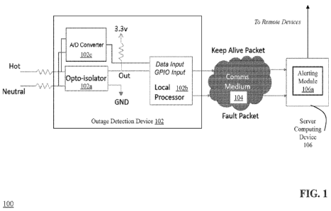
of aging and exposure to the environment. Switching between various generation
types can cause
surges and sags in voltage, and other power quality concerns. Aging and
environmental exposure
causes transformers and electrical inter-connections to deteriorate and fail.
Surges, sags and
deteriorating equipment can cause home electronics and appliances to fail as
well as create very
dangerous situations where electrocution and electrical fires can occur. In a
residential setting, fires
often begin in walls or other hidden cavities and gain significant heat and
headway before they are
detected by home occupants or smoke detectors, leading to significant damage.
Electrical
malfunctions are one of the leading causes of residential home fires. Because
of the hidden nature of
the ignition source, electrical fires are also a disproportionate cause of
death. Electrical fires are
estimated to cause 420 deaths, 1,370 injuries, and $1.4B in residential
damages annually.
[0006] Current technology does not provide a homeowner with much needed
information
about the quality of power they receive from the utility. For example, a
homeowner may be aware
of lights flickering or frequent loss of sensitive electronics equipment
without being alerted to very
serious issues in the electrical connection to their home or within the home's
electrical network.
Furthermore, damage to and deterioration of the United States electric grid is
increasing risk and
liability for the grid's utility owners and their customers. For example, a
recent Pacific Gas & Energy
(PG&E) Fire Incident Data Report shows that PG&E experienced over 2,400 grid-
caused fires from
2014 through 2019. These fires resulted in excess of $13B in liability and
precipitated PG&E's filing
for bankruptcy. In another example, a Texas Wildfire Mitigation Project study
found that 4,000 fires,
2
CA 03174492 2022-09-01
WO 2021/183933 PCT/US2021/022176
most local and of little consequence, but also larger conflagrations, were
caused by utility
transmission or distribution system events taking place in a period of less
than four years preceding
that study. In addition to wildfires, increases in transformer fires and
explosions and other
catastrophic grid events are linked to deteriorating utility equipment. In one
horrific example, in mid-
July of 2019 firefighters were called to downtown Madison, Wisconsin, where a
high-voltage
transformer had exploded and caught fire. Another recent event was the
American Electric Power
(AEP) Texas substation transformer explosion and fire at the end of July 2019.
Finally, in February
2021, the state of Texas experienced a devastating failure of its power grid
due to a severe winter
storm, resulting in loss of life and millions of people without electricity in
below-freezing
temperatures.
[0007] As noted above, utility grid-caused fires have resulted in very
large economic damage,
and often significant mortality, every year. Many power system components
(e.g., switches,
insulators, transformers) provide trouble-free service for decades, but
transmission and distribution
components eventually fail. Wildfires and other damage to property and life
can be triggered via a
number of mechanisms including: downed lines, vegetation contact, conductor
slap, arcing of
damaged or deteriorating equipment, repetitive faults, and apparatus failures.
Therefore, rapid
detection and mitigation of these issues is crucial to preventing catastrophic
fire events.
SUMMARY
[0008] Therefore, what is needed is are methods and systems for detecting
power outages and
power quality in electrical systems in real time or near real time, and for
notifying relevant users
(including electrical grid operators and/or governmental officials) of the
outages and/or undesirable
changes in power quality or hazardous conditions in the electrical system. The
techniques described
herein advantageously provide for the detection of power outages, evaluation
of power quality, and
identification of electrical system hazards based upon detected frequency of
alternating current (AC)
electricity received by an outage detection device, and also provide for
immediate notification of the
3
CA 03174492 2022-09-01
WO 2021/183933 PCT/US2021/022176
power outages to remote devices¨including in some embodiments, using
communication equipment
that is powered by the electrical system that experiences the outage right
before the communication
equipment goes offline due to the outage. Also, in some embodiments, the
methods and systems
described herein leverage a single monitoring device, or a few monitoring
devices, that plug into an
existing electrical outlet¨instead of complicated, expensive, or dangerous
installation of other power
outage detection devices and/or monitoring components (such as connecting to
circuit breakers or
electrical panels). The technology described herein not only beneficially
provides homeowners and
business owners insight into power quality and potential for hazards, but with
multiple homes using
the methods and systems described herein, the technology provides insight to
utilities about any issues
and give them the ability to be proactive to fix issues before a hazard
becomes dangerous.
[0009] The invention, in one aspect, features a system for detection and
notification of
electrical power outages. The system comprises a sensor device coupled to a
circuit and a server
computing device. The sensor device periodically transmits a keepalive packet
to the server
computing device. The sensor device detects an input signal generated by
electrical activity on the
circuit. The sensor device generates an output signal based upon the detected
input signal. The sensor
device monitors the generated output signal during each of a plurality of
clock cycles having a
predefined duration. During each clock cycle, the sensor device determines
whether a rising edge
occurred in the generated output signal and transmits a fault packet to the
server computing device
when the rising edge occurred prior to a predetermined clock value in the
clock cycle or when no
rising edge occurred in the clock cycle. The sensor device initiates a new
clock cycle. The server
computing device receives the fault packet from the sensor device. The server
computing device
listens for one or more keepalive packets from the sensor device. The server
computing device
transmits a power outage notification to one or more remote computing devices
when no keepalive
packets are received from the sensor device for at least a defined time period
after the fault packet is
received. The server computing device transmits a power restoration
notification to the one or more
4
CA 03174492 2022-09-01
WO 2021/183933 PCT/US2021/022176
remote computing devices when one or more keepalive packets are subsequently
received from the
sensor device after the power outage notification is transmitted.
[0010] The invention, in another aspect, features a computerized method
of detection and
notification of electrical power outages. A sensor device coupled to a circuit
periodically transmits a
keepalive packet to a server computing device. The sensor device detects an
input signal generated
by electrical activity on the circuit. The sensor device generates an output
signal based upon the
detected input signal. The sensor device monitors the generated output signal
during each of a
plurality of clock cycles having a predefined duration. During each clock
cycle, the sensor device
determines whether a rising edge occurred in the generated output signal and
transmits a fault packet
to the server computing device when the rising edge occurred prior to a
predetermined clock value in
the clock cycle or when no rising edge occurred in the clock cycle. The sensor
device initiates a new
clock cycle. The server computing device receives the fault packet from the
sensor device. The
server computing device listens for one or more keepalive packets from the
sensor device. The server
computing device transmits a power outage notification to one or more remote
computing devices
when no keepalive packets are received from the sensor device for at least a
defined time period after
the fault packet is received. The server computing device transmits a power
restoration notification
to the one or more remote computing devices when one or more keepalive packets
are subsequently
received from the sensor device after the power outage notification is
transmitted.
[0011] Any of the above aspects can include one or more of the following
features. In some
embodiments, the input signal comprises an alternating current (AC) voltage
sine wave with a
plurality of zero crossings. In some embodiments, the output signal is a
voltage curve having a
plurality of rising edges corresponding to the zero crossings of the input
signal. In some
embodiments, the keepalive packet comprises power quality data including one
or more of: root mean
square (RMS) voltage, frequency of the voltage sine wave, relative phase angle
of the voltage sine
wave, amplitude of the voltage sine wave harmonics, or any number of measures
of high frequency
CA 03174492 2022-09-01
WO 2021/183933 PCT/US2021/022176
noise amplitude. In some embodiments, each clock cycle has a predefined
duration of 9 milliseconds.
In some embodiments, the predetermined clock value in the clock cycle is 8.33
milliseconds.
[0012] The invention, in another aspect, features a system for detection
and notification of
electrical power quality. The system comprises one or more sensor devices
coupled to a circuit and
a server computing device. The one or more sensor devices detect an input
signal generated by
electrical activity on the circuit. The one or more sensor devices generate an
output signal based
upon the detected input signal. The one or more sensor devices transmit power
quality data to the
server computing device, the power quality data based upon the output signal.
The server computing
device receives the power quality data from the one or more sensor devices.
The server computing
device analyzes the power quality data in conjunction with historical power
quality data received
from the one or more sensor devices to detect one or more power quality
events. The server
computing device transmits a power quality notification to one or more remote
computing devices
based upon the detected power quality events.
[0013] The invention, in another aspect, features a computerized method
of detection and
notification of electrical power quality. A sensor device coupled to a circuit
detects an input signal
generated by electrical activity on the circuit. The sensor device generates
an output signal based
upon the detected input signal. The sensor device transmits power quality data
to a server computing
device, the power quality data based upon the output signal. The server
computing device receives
the power quality data from the sensor device. The server computing device
analyzes the power
quality data in conjunction with historical power quality data received from
the sensor device to detect
one or more power quality events. The server computing device transmits a
power quality notification
to one or more remote computing devices based upon the detected power quality
events.
[0014] Any of the above aspects can include one or more of the following
features. In some
embodiments, the detected one or more power quality events comprise one or
more of: surge events,
surge jump events, sag events, sag jump events, brownout events, swell jump
events, high frequency
(HF) filter jump events, frequency jump events, recurring power quality
problems, phase angle jump
6
CA 03174492 2022-09-01
WO 2021/183933 PCT/US2021/022176
events, loose neutral events, or generator activation events. In some
embodiments, the server
computing device further correlates (i) the detected one or more power quality
events with zero or
more external events and/or (ii) a detected power quality event from a first
sensor device with a
detected power quality event from one or more other sensor devices.
[0015] In some embodiments, the server computing device detects a loose
neutral event by:
analyzing, for a single sensor device, a number and amplitude of surge events,
surge jump events,
and sag events recorded by the single sensor device within a predetermined
time period which do not
correlate with matching power quality events from any other sensor devices in
proximity to the single
sensor device; and generating a loose neutral event when an average number of
the surge events is
greater than a first defined number per day, or an average number of the surge
jump events having a
magnitude greater than a defined percentage of a nominal voltage is greater
than a second defined
number per day, or an average number of the sag events is greater than a third
defined number per
day.
[0016] In some embodiments, the output signal comprises one or more of:
root mean square
(RMS) voltage, frequency of the voltage sine wave, relative phase angle of the
voltage sine wave,
amplitude of the voltage sine wave harmonics, or any number of measures of
high frequency noise
amplitude. In some embodiments, the server computing device detects a surge
event by: analyzing a
plurality of sequential data points of RMS voltage from one or more sensor
devices; and generating
a surge event when the RMS voltage is greater than a predefined threshold
percentage of a nominal
voltage for a number of consecutive data points. In some embodiments, the
predefined threshold
percentage varies based upon the number of consecutive data points in which
the RMS voltage is
greater than a minimum threshold percentage.
[0017] In some embodiments, the server computing device detects a
brownout event by:
analyzing a plurality of sequential data points of RMS voltage from one or
more sensor devices; and
generating a brownout event when the RMS voltage is less than a predefined
threshold percentage of
a nominal voltage for a number of consecutive data points. In some
embodiments, the predefined
7
CA 03174492 2022-09-01
WO 2021/183933 PCT/US2021/022176
threshold percentage varies based upon the number of consecutive data points
in which the RMS
voltage is less than a minimum threshold percentage.
[0018] In some embodiments, the server computing device detects a sag
jump event by:
analyzing a plurality of sequential data points of RMS voltage from one or
more sensor devices; and
generating a sag jump event for each of one or more drops of RMS voltage that
occurred in the
plurality of sequential data points and that are larger than a predefined
threshold percentage of a
nominal voltage.
[0019] In some embodiments, the server computing device detects a swell
jump event by:
analyzing a plurality of sequential data points of RMS voltage from one or
more sensor devices; and
generating a swell jump event for each of one or more increases of RMS voltage
that occurred in the
plurality of sequential data points and that are larger than a predefined
threshold percentage of a
nominal voltage.
[0020] In some embodiments, the server computing device detects a HF
Filter jump event by:
analyzing a plurality of sequential data points of HF amplitude data from one
or more sensor devices;
calculating a mean of the HF amplitude data; and when the mean is greater than
one, generating an
HF Filter jump event when the HF amplitude data increases by more than a
threshold multiple of the
mean, or when the mean is less than one, generating an HF Filter jump event
when the HF amplitude
data increases above a predefined threshold.
[0021] In some embodiments, the server computing device detects a
frequency jump event
by: analyzing a plurality of sequential data points of frequency data from one
or more sensor devices;
calculating an average of the frequency data; calculating a standard deviation
of the frequency data;
and generating a frequency jump event when the frequency increases by more
than a predefined
threshold from the average, or generating a frequency jump event when (i) the
standard deviation
changes from less than a first frequency to greater than a second frequency or
(ii) the standard
deviation changes from greater than the second frequency to less than the
first frequency.
8
CA 03174492 2022-09-01
WO 2021/183933 PCT/US2021/022176
[0022] In some embodiments, the server computing device detects a
generator activation
event by: analyzing, for a single sensor device, whether any power outage
events and frequency
events were detected by the single sensor device during a predetermined time
period; and generating
a generator activation event when the single sensor device detected a power
outage event followed
by a frequency standard deviation change to greater than a predefined
threshold within a defined
period of time of the power outage event and the frequency standard deviation
change was not
associated with a correlated external event.
[0023] In some embodiments, the one or more external events comprise
lightning activity
events, electrical grid monitoring events, and energy pricing events. In some
embodiments, the
detected power quality event from the first sensor device and the detected
power quality event from
one or more other sensor devices are of a same event type. Such power quality
events that have the
same event type (including but not limited to the same or similar power
quality characteristics,
durations, start times, stop times, geographic locations, and the like) are
referred to herein as
"correlated events" or "matching events."
[0024] Other aspects and advantages of the invention will become apparent
from the
following detailed description, taken in conjunction with the accompanying
drawings, illustrating the
principles of the invention by way of example only.
BRIEF DESCRIPTION OF THE DRAWINGS
[0025] The advantages of the invention described above, together with
further advantages,
may be better understood by referring to the following description taken in
conjunction with the
accompanying drawings. The drawings are not necessarily to scale, emphasis
instead generally being
placed upon illustrating the principles of the invention.
[0026] FIG. 1 is a block diagram of a system for detection and
notification of electrical power
outages.
9
CA 03174492 2022-09-01
WO 2021/183933 PCT/US2021/022176
[0027] FIGS. 2A and 2B comprise a flow diagram of a computerized method
of detection and
notification of electrical power outages.
[0028] FIG. 3 is a diagram of an exemplary 60 Hz voltage signal captured
by the outage
detection device.
[0029] FIG. 4 is a diagram of an exemplary input signal received by the
outage detection
device and an exemplary output signal generated by the outage detection
device.
[0030] FIG. 5A is a detailed timing diagram showing the output signal
generated by the
outage detection device and the corresponding value of the global power outage
flag when power
outages are detected by the outage detection device.
[0031] FIG. 5B is a graph of output signals from a plurality of different
outage detection
devices when a power outage has occurred.
[0032] FIG. 6A is an exemplary user interface of a remote computing
device that depicts a
power outage notification received from the server computing device.
[0033] FIG. 6B is an exemplary user interface of a remote computing
device that depicts a
power restoration notification received from the server computing device
[0034] FIG. 7 is a diagram which shows the results of testing the
detection efficiency of the
outage detection device.
[0035] FIG. 8 is a graph of the ITI (CBEMA) curve.
[0036] FIG. 9 is a block diagram of a networked system for power quality
detection and
notification.
[0037] FIG. 10 is a flow diagram of a computerized method of analyzing
power quality data.
[0038] FIG. 11 is a graph showing the output signal generated by a
plurality of different
outage detection devices during a grid surge event.
[0039] FIG. 12 is a graph showing the output signal generated by a
plurality of different
outage detection devices during a brownout event.
CA 03174492 2022-09-01
WO 2021/183933 PCT/US2021/022176
[0040] FIG. 13 is a graph showing the output signal generated by a
plurality of different
outage detection devices during a sag jump event.
[0041] FIG. 14 is a graph showing the output signal generated by a
plurality of different
outage detection devices during a swell jump event.
[0042] FIG. 15 is a graph showing the output signal generated by a
plurality of different
outage detection devices during a HF Filter jump event.
[0043] FIG. 16 is a graph showing the output signal generated by a
plurality of different
outage detection devices during a frequency jump event.
[0044] FIG. 17A is a graph of nominal Voltage Root Mean Square (RMS)
readings captured
by an outage detection device.
[0045] FIG. 17B is a graph of Voltage RMS readings captured by an outage
detection device
showing an example loose neutral connection.
[0046] FIG. 17C is a graph of Voltage RMS readings captured by an outage
detection device
before and after resolution of a loose neutral connection.
[0047] FIG. 18 is a diagram of a user interface displayed on a remote
computing device that
shows historical Voltage RMS readings detected by an outage detection device.
[0048] FIG. 19 is a diagram of a user interface displayed on a remote
computing device that
shows a month's worth of power quality events detected by an outage detection
device.
[0049] FIG. 20A is a diagram of a user interface that shows push
notification alerts sent by
the server computing device to a remote computing device for display.
[0050] FIG. 20B is a diagram of a user interface that shows a list of
power quality notifications
relating to an outage detection device.
[0051] FIG. 20C is a diagram of a user interface that shows a detailed
power surge event alert
notification sent by the server computing device to a remote computing device
for display.
[0052] FIG. 20D is a diagram of a user interface that shows a detailed
power brownout event
alert notification sent by the server computing device to a remote computing
device for display.
11
CA 03174492 2022-09-01
WO 2021/183933 PCT/US2021/022176
[0053] FIG. 20E is a diagram of a user interface that shows a recurring
power quality
problems alert notification sent by the server computing device to a remote
computing device for
display.
[0054] FIG. 21A is a diagram of a geographic map generated by the server
computing device
that depicts the location of detected power outage events by a network of
outage detection devices.
[0055] FIG. 21B is a diagram of a detail view of the geographic map
generated by the server
computing device that depicts the location of detected power outage events by
a network of outage
detection devices.
[0056] FIG. 22A is a diagram of a geographic map generated by the server
computing device
that depicts the location of detected grid surge and brownout events by a
network of outage detection
devices.
[0057] FIG. 22B is a diagram of a detail view of the geographic map
generated by the server
computing device that depicts the location of detected grid surge and brownout
events by a network
of outage detection devices.
[0058] FIG. 23 is a diagram of a detail view of a geographic map
generated by the server
computing device that depicts the location of detected grid sag jump events by
a network of outage
detection devices.
[0059] FIG. 24 is a diagram of a detail view of a geographic map
generated by the server
computing device that depicts the location of detected grid swell jump events
by a network of outage
detection devices.
[0060] FIG. 25A is a diagram of a geographic map generated by the server
computing device
that depicts the location of detected grid frequency jump events by a network
of outage detection
devices.
[0061] FIG. 25B is a diagram of a detail view of the geographic map
generated by the server
computing device that depicts the location of detected grid frequency jump
events by a network of
outage detection devices.
12
CA 03174492 2022-09-01
WO 2021/183933 PCT/US2021/022176
[0062] FIG. 26 is a diagram of a geographic map generated by the server
computing device
that depicts the location of detected high frequency (HF) filter jump events
by a network of outage
detection devices.
DETAILED DESCRIPTION
[0063] FIG. 1 is a block diagram of a system 100 for detection and
notification of electrical
power outages. The system 100 includes an outage detection device 102, a
communications medium
104, and a remote computing device 106. The outage detection device 102
comprises an opto-isolator
102a that connects to the hot wire and neutral wire of the electrical power
system in order to monitor
electrical current (e.g., 120 VAC, 60 Hz) for the purposes described herein.
The opto-isolator 102a
is also connected to a ground (GND). An exemplary 60 Hz voltage signal
captured by the outage
detection device is shown in FIG. 3. The opto-isolator 102a generates an
output signal (Out) based
upon the received electrical current that is provided to a processor 102b of
the outage detection device
102. The processor 102b analyzes the output signal from the opto-isolator 102a
and transmits data
(e.g., packet-based communication) to a server computing device 106 which,
based upon the data
received from the outage detection device 102, can transmit outage
notifications to one or more
remote computing devices (not shown). An exemplary power outage detection
device 102 is the
TingTm Sensor available from Whisker Labs, Inc. of Germantown, Maryland.
[0064] The outage detection device 102 also contains an Analog-to-Digital
(A/D) converter
102c which reads input signals from the hot wire and neutral wire. In some
embodiments, the input
signals may be filtered or transformed prior to the signals being read by the
A/D converter 102c. The
A/D converter 102c generates certain power quality data to transmit to the
server, including but not
limited to RMS Voltage, Peak Voltage, Frequency, Phase, High Frequency (HF)
amplitude and
amplitudes of harmonics. It can be appreciated that other power quality
measures can be calculated
and this list is not meant to be exhaustive. Power quality data is transmitted
regularly to the server
13
CA 03174492 2022-09-01
WO 2021/183933 PCT/US2021/022176
computing device at a regular time interval and is included as part of the
"keep alive packet" shown
in FIG. 1 and described herein.
[0065] The communications medium 104 enables the other components of the
system 100 to
communicate with each other in order to perform the process of detection and
notification of electrical
power outages as described herein. The medium 104 may be a local network, such
as a LAN
including one or more components (e.g., routers, modems) connected to the
electrical wiring that is
being monitored by the system 100, or a wide area network, such as the
Internet and/or a cellular
network. In some embodiments, the network 104 is comprised of several discrete
networks and/or
sub-networks (e.g., cellular to Internet) that enable the components of the
system 100 to communicate
with each other. The communications medium 104 can comprise wired and/or
wireless components.
[0066] The server computing device 106 is a combination of hardware,
including one or more
special-purpose processors and one or more physical memory modules, and
specialized software
modules that are executed by a processor of the server computing device 106,
to receive data from
other components of the system 100, transmit data to other components of the
system 100, and
perform functions for detection and notification of electrical power outages
as described herein. In
some embodiments, the server computing device 106 comprises an alerting module
106a, which is a
specialized set of computer software instructions programmed onto a dedicated
processor in the
server computing device 106 and can include specifically-designated memory
locations and/or
registers for executing the specialized computer software instructions.
Further explanation of the
specific processing performed by the alerting module 106a will be provided
below.
[0067] As can be appreciated, in some cases it is beneficial to correlate
other outside events
(e.g., events that are external to the power grid / power system) with power
quality events. For
example, if a lightning strike is closely correlated with a surge power
quality event, then the system
100 can issue a more urgent notification warning to the end user (e.g., a
visual and audible alert
message on multiple end user devices), especially if the amplitude of the
surge event is at an
amplitude which could cause significant damage to appliances in the home. A
homeowner may be
14
CA 03174492 2022-09-01
WO 2021/183933 PCT/US2021/022176
extra vigilant to monitor immediate hazards in the home if he or she knows
that a very strong surge
was caused by a direct hit of a lightning strike. It may also be beneficial to
correlate power quality
events with other grid monitoring devices such as an automatic circuit
recloser device. In this way, a
utility could utilize the technology described herein to correlate events from
the recloser device to
power quality events in a home or business. External events can be correlated
with power quality
events to limit the distribution or to elevate the criticality of the
notification to the end users.
[0068] In some embodiments, the outage detection device 102 is coupled
via a 120 VAC plug
to an electrical outlet of a branch circuit in a building electrical system,
which in turn is connected to
a utility power grid. Although FIG. 1 depicts a single outage detection device
102, it should be
appreciated that the system 100 can comprise two or more outage detection
devices positioned to
sense electrical activity in a power distribution system. Multiple sensors
sending data to a server
computing device can provide increased sensitivity and work together to
provide information on the
power outages and power quality of the electrical system and/or power grid. It
should be further
appreciated that a single location (e.g., a home) may have multiple outage
detection devices installed,
and also that the system 100 can be configured to receive data from a
plurality of outage detection
devices each installed in a different location (as described below with
respect to FIG. 9).
[0069] As noted above, the outage detection device 102 is communicably
coupled to server
computing device 106 via a communication medium 104. In one embodiment, the
outage detection
device 102 is equipped with communication components (e.g., antenna, network
interface circuitry)
that enable the outage detection device 102 to communicate with the server
computing device 106
via a wireless connection (i.e., using wireless components such as routers
and/or modems of the
communication medium 104).
[0070] FIGS. 2A and 2B comprise a flow diagram of a computerized method
200 of detection
and notification of electrical power outages, using the system 100 of FIG. 1.
An outage detection
device (e.g., outage detection device 102), coupled to a branch circuit of a
power distribution system,
detects (202) an input signal generated by electrical activity on the branch
circuit. The outage
CA 03174492 2022-09-01
WO 2021/183933 PCT/US2021/022176
detection device 102 generates (204) an output signal based upon the detected
input signal. FIG. 4
is a diagram of an exemplary input signal 402 received by the outage detection
device 102 and an
exemplary output signal 404 generated by the outage detection device 102. As
shown in FIG. 4, the
input signal 402 comprises a typical alternating current (AC) voltage signal
(such as an AC sine wave)
with zero crossings (e.g., 402a, 402b) occurring approximately 8.33
milliseconds (ms) apart.
[0071] The opto-isolator 102a of outage detection device 102 receives the
input signal 402
via the hot and neutral connections to the power distribution system
(including the electrical grid)
and converts the input signal 402 into the output signal 404. As shown in FIG.
4, the output signal
404 comprises a voltage curve having a plurality of rising edges (e.g., 404a,
404b) that generally
correspond to the zero crossings of the input signal 402, in that the rising
edges occur approximately
8.33 ms apart. The diagram 406 in FIG. 4 depicts the input signal 402 and the
output signal 404
superimposed, to show the correspondence of the signals. It should be
appreciated that, depending
upon the electrical system to which the outage detection device 102 is coupled
(including the
spectrum of electronic devices that may be coupled to the electrical system),
one or more different
points on the plurality of rising edges in the output signal 404 can
correspond to the zero crossings of
the input signal 402¨for example, the start of the rising edges in the output
signal 404 can correspond
to the zero crossings of the input signal 402, the midpoint between start and
peak of the rising edges
can correspond to the zero crossings, or the peak of the rising edges can
correspond to the zero
crossings. It should further be appreciated that the same points on each
rising edge (e.g., start,
midpoint, peak) should occur approximately 8.33 ms apart. The output signal
404 is transmitted to
the processor embedded in the outage detection device (see FIG. 1), which
monitors the output signal
404 as described below. It should be appreciated that the exact timing of the
zero crossings described
herein is for example purposes only, and corresponds to standard timing of
U.S. power systems. The
algorithms and techniques described herein here can be modified to
automatically detect and adjust
to differing timing of international power systems.
16
CA 03174492 2022-09-01
WO 2021/183933 PCT/US2021/022176
[0072] Turning back to FIG. 2A, when the outage detection device 102 is
powered up and
connected to the server computing device 106, the outage detection device 102
periodically transmits
(206) a keepalive packet to the alerting module 106a of server computing
device 106. The keepalive
packet is used to inform the server computing device 106 that the outage
detection device 102 is
receiving electrical power (i.e., there is no power outage at the
corresponding location) and that the
outage detection device 102 is online. For example, the processor 102b of the
outage detection device
102 executes a main thread that runs continuously and sends the keepalive
packet to the server
computing device 106 at a regular 1/4 second interval. In some embodiments,
the keepalive packet
can additionally contain other regularly monitored data that is generated by
the A/D converter 102c
as described above, such as the measured root mean square (RMS) voltage of the
power distribution
system, the frequency of the voltage sine wave, the relative phase angle of
the sine wave, amplitude
of the sine wave harmonics and any number of measures of the high frequency
noise amplitude.
Examples of certain, non-limiting types of power quality data that can be
captured and transmitted
by the outage detection device 102 are described in U.S. Patent No.
10,641,806, titled "Detection of
Electric Discharges that Precede Fires in Electrical Wiring," which is
incorporated herein by
reference.
[0073] In addition, the main thread monitors a global power outage flag.
When the power
outage flag is set (e.g., to 1), the main thread sends a fault packet to the
server computing device 106
(e.g., indicating a power outage) and resets the power outage flag to 0.
Additional detail about the
power outage flag and fault packet is described below.
[0074] The outage detection device 102 monitors (208) the generated
output signal during
each of a plurality of clock cycles having a defined duration. For example,
the processor 102b of
outage detection device 102 can create a timer (or timeout clock) that
cyclically counts down from 9
ms (-55 Hz frequency) to zero, and then resets. When the timer reaches zero,
the processor 102b
calls an interrupt to the main thread (the "timeout interrupt"). In addition,
the processor 102b calls
17
CA 03174492 2022-09-01
WO 2021/183933 PCT/US2021/022176
an interrupt to the main thread (the "opto-isolator interrupt") when the
processor detects a rising edge
in the output signal (i.e., signal 404 in FIG. 4) received from the opto-
isolator 102a.
[0075] When the processor 102b calls the opto-isolator interrupt, the
processor 102b of outage
detection device 102 determines (210) whether a rising edge occurred in the
generated output signal
404. For example, the processor 102b counts how many clock ticks occurred
since the time of the
last opto-isolator interrupt. When either (i) a rising edge occurred in the
generated output signal 404
prior to a predetermined clock value in the clock cycle (for example, if the
last opto-isolator interrupt
occurred less than 7.6 ms ago (-65 Hz frequency) or (ii) a rising edge did not
occur in the generated
output signal 404 during the clock cycle (for example, the last opto-isolator
interrupt occurred more
than 9 ms ago¨thereby triggering the timeout interrupt described above), this
indicates a loss of
power. As a result, the processor 102b sets the global power outage flag to 1.
As described above,
the main thread executed by the processor 102b is monitoring the global power
outage flag and when
the main thread sees the flag set to 1, the processor of output detection
device 102 transmits (212) a
fault packet to the alerting module 106a of server computing device 106 and
initiates (214) a new
clock cycle for monitoring the generated output signal 404 (e.g., by reloading
or resetting the timeout
clock to 9 ms).
[0076] FIG. 5A is a detailed timing diagram showing the output signal
generated by the
outage detection device 102 and the corresponding value of the global power
outage flag when power
outages are detected by the outage detection device 102. As shown in FIG. 5A,
the trace 510
corresponds to the output signal 404 generated by the outage detection device
102. The solid black
line 502 indicates the value of the global power outage flag in the main
thread of the processor 102b,
and the dotted black line 504 indicates when the main thread finishes sending
a fault packet to the
server computing device 106. For example, the processor 102b detects a power
outage at time ti and
sets the global power outage flag to 1. Then, at time t2, the main thread of
processor 102b reads the
global power outage flag as 1 and starts transmitting a fault packet to server
computing device 106.
At time t3, the main thread finishes sending the fault packet to server
computing device 106. The
18
CA 03174492 2022-09-01
WO 2021/183933 PCT/US2021/022176
processor 102b detects a second power outage at time t4 (which could
correspond to the same overall
power outage) and begins transmitting a second fault packet to server
computing device at time t5.
Then, at time t6, the processor 102b finishes sending the second fault packet.
[0077] Alternatively, when a rising edge occurred in the generated output
signal 404 at a
predetermined clock value in the clock cycle (i.e., at approximately 8.33 ms),
the opto-isolator
interrupt process does not set the global power outage flag to 1 (and the
timeout interrupt does not
trigger). As a result, the processor 102b of output detection device 102
merely initiates (214) a new
clock cycle for monitoring the generated output signal 404 (e.g., by reloading
or resetting the timeout
clock to 9 ms).
[0078] FIG. 5B is a graph of output signals from a plurality of different
outage detection
devices when a power outage has occurred. As shown in FIG. 5B, each line
(e.g., line 512)
corresponds to voltage readings from an output signal of a different outage
detection device. Shortly
before 05:48, a power outage occurred¨which is reflected in the graph at line
ti where the readings
from each device suddenly stop. In the following few minutes, power is
restored at different times
to each of the outage detection devices¨indicated by the arrows labeled 'power
restoration.'
[0079] Turning to FIG. 2B, in the event that the outage detection device
102 transmits a fault
packet to the server computing device 106, the alerting module 106a receives
(216) the fault packet
and listens (218) for keepalive packets from the outage detection device 102.
As described
previously, the main thread of the processor 102b of outage detection device
102 is configured to
transmit a keepalive packet to the server computing device 106 every 1/4
second. When the alerting
module 106a receives a fault packet and does not subsequently detect any
keepalive packets for at
least a defined time period (e.g., 5 seconds) after the fault packet is
received, the alerting module
106a transmits (220) a power outage notification to one or more remote
computing devices.
[0080] In some embodiments, the alerting module 106a can transmit the
power outage
notifications via one or more communications channels and/or communication
protocols¨such as
email, text (e.g., SMS), automated phone call¨to remote computing devices like
mobile phones,
19
CA 03174492 2022-09-01
WO 2021/183933 PCT/US2021/022176
smart watches, smart devices, tablets, laptops, etc. In some embodiments, the
alerting module 106a
can transmit the power outage notifications to computing devices associated
with different
organizations via, e.g., webhook API callbacks, or by utilizing services from
cloud computing
providers such as Amazon Web Services (AWS) Simple Notification Service. In
one example, the
remote computing device can comprise a mobile application (app) that is
configured to receive push
notifications from the alerting module 106a that, when received, automatically
activate functionality
of the mobile app to alert a user of the remote computing device (e.g., pop-up
message, audible alert,
and/or haptic alert (vibration)) that a power outage is occurring at the
corresponding location of the
outage detection device 102. FIG. 6A is an exemplary user interface of a
remote computing device
(e.g., a smart phone) that depicts a power outage notification received from
the alerting module 106a.
As shown in FIG. 6A, the power outage notification includes a visual symbol
602 indicating a power
outage event and a detailed description 604 including a time and location of
the power outage.
[0081] After transmitting the power outage notification, the alerting
module 106a returns to
listening for keepalive packets from the outage detection device 102. When the
alerting module 106a
subsequently detects one or more keepalive packets (either within the defined
time period or after the
defined time period has elapsed) after the power outage notification is
transmitted, the alerting
module 106a transmits (222) a power restoration notification to the one or
more remote computing
devices. As described above with respect to the power outage notification, the
remote computing
devices can receive the power restoration notification from the alerting
module 106a and activate
functionality of the remote computing device to alert a user of the device
that power has been restored.
FIG. 6B is an exemplary user interface of a remote computing device that
depicts a power restoration
notification received from the alerting module 106a. As shown in FIG. 6B, the
power restoration
notification includes a visual symbol 606 indicating a power restoration event
and a detailed
description 608 including a time and location of the power restoration.
[0082] It should be appreciated that reliability of the power outage
detection methodology
described herein can depend upon the connectivity between the outage detection
device 102 and the
CA 03174492 2022-09-01
WO 2021/183933 PCT/US2021/022176
server computing device 106, as well as depending upon the availability of
intermediate equipment
which supports that connectivity. For example, the power outage detection
device 102 may be
connected to a local WiFi router (e.g., installed in a home or business),
which in turn is connected to
an internet modem or router, which in turn is connected to other components
within a corresponding
Internet provider's network before the connection finally reaches the server
computing device 106
that detects the power outage event. As a result, the fault packets must be
sent by the outage detection
device 102 and traverse each segment of the communication medium 104 (e.g.,
network) which may
or may not be powered by the same power distribution system and power lines
before one or more of
these devices loses power and can no longer transmit, re-transmit, and/or
relay the fault packets to
the next link in the overall connection. It should be appreciated that if the
fault packets do not reach
the server computing device 106, then the server computing device 106 cannot
distinguish if the
keepalive packets stopped because of loss of communication connectivity (e.g.,
an Internet outage)
or instead due to a power outage at the location of the outage detection
device 102. Therefore, rapid
detection of power outages and transmission of fault packets is essential to
the advantages provided
by the methods and systems described herein.
[0083] In order to determine the effectiveness of detecting power outages
using this method,
tests were performed using two power outage detection devices set up in two
different locations. Each
power outage detection device was placed on a programmable switch so that
power could be turned
off automatically once per day over several months. FIG. 7 is a diagram which
shows the results of
the testing. As shown in FIG. 7, the power outage detection devices 102
successfully detected power
outages 95% of the time on average, with a maximum of 100% detection
efficiency and a minimum
of 71% detection efficiency.
[0084] Also, it should be appreciated that another advantage provided by
the techniques
described herein is the improved power outage detection and notification
efficiency with scale of
installation of the power outage detection devices in proximity to each other.
For example, when
multiple power outage detection devices are in proximity to each other, for
example on the same
21
CA 03174492 2022-09-01
WO 2021/183933 PCT/US2021/022176
voltage transformer which powers multiple homes, the efficiency of detecting
power outages
increases. If a power outage detection device 102 installed in at least one of
the homes on the same
electrical network is able to communicate a fault packet to the server
computing device 106, and the
keepalive packets stop arriving at the same time, then a power outage
notification can be sent to
remote devices associated with each customer on the network. The same approach
can be used for a
wider area electrical grid outage: if dozens of homes are powered by the same
substation, then in the
event of a power outage at that substation, only one power outage detection
device 102 installed at a
single home of the dozens of homes serviced by the substation needs to
successfully transmit a fault
packet to the server computing device 106 in order to generate a power outage
notification to a remote
device associated with customers in each of the dozens of homes. Conversely,
if a dozen homes are
powered by the same substation and the outage detection device 102 installed
at each of the homes
does not transmit a fault packet prior to loss of communications of the
keepalive packets, then it can
be safely assumed that the outage was the result of another non-power related
occurrence (e.g., an
Internet Service Provider (ISP) outage), and not the result of loss of power.
[0085] Another important feature of the methods and systems described
herein is the
capability to monitor the power quality of the electrical power received by
the outage detection device
102 of the system 100 and provide information relating to the power monitoring
to both customers
(e.g., the homeowner where the power outage detection device 102 is installed)
and utility providers.
As mentioned previously, the power outage detection device 102 can capture
additional data about
the electrical power during its regular monitoring for power outages (such as,
e.g., measured root
mean square (RMS) voltage of the power distribution system, the frequency of
the voltage sine wave,
the relative phase angle of the sine wave, amplitude of the sine wave
harmonics and any number of
measures of the high frequency noise amplitude), and the outage detection
device 102 can transmit
the data to the server computing device 106 (e.g., as part of the transmission
of keepalive packets to
the server computing device).
[0086] As will be described in greater detail below, the outage detection
device 102 can send
22
CA 03174492 2022-09-01
WO 2021/183933 PCT/US2021/022176
Vrms samples of the voltage to the server computing device 106 each 1/4 second
(or 20 Vrms
readings per second). This enables the server computing device 106 to monitor
for surges and sags in
the voltage, which can cause damage to appliances or sensitive electronics
devices that are also
coupled to the power distribution system. FIG. 8 is a graph known as the ITI
(CBEMA) curve. The
graph shows the acceptable voltage levels within an envelope of voltage
amplitude over a time
duration. For example, a very short duration (-16 milliseconds) with a large
voltage amplitude (300
volts) generally does not impact a device being powered on a circuit, but if
the voltage amplitude
remains at 300 volts for more than five seconds, it could cause damage to any
devices on the electrical
network. Additionally, when multiple power outage or surge and sag events
occur over many days
for a single location, it is recommended that the customer reach out to their
electric utility. Recurring
power quality problems can cause damage to appliances and sensitive
electronics and may indicate
more severe problems with electrical power lines coming to the residence which
could cause electrical
fires.
[0087] For example, if the amplitude and duration of voltage data
streaming to the alerting
module 106a exceed the bounds of the CBEMA curve above nominal voltage levels,
the alerting
module 106a sends a "Power Surge" notification message to the device of the
end user. If the
amplitude and duration of voltage data streaming to the alerting module 106a
exceed the bounds of
the CBEMA curve below nominal voltage levels, the alerting module 106a sends a
"Power
Brownout" notification to the end user's device.
[0088] In some embodiments, other information gathered from the voltage
signal can also
indicate power quality problems. For example, a measurement of the voltage
sine wave frequency
which has a very high variance might signal that the home is no longer using
utility power, but has
switched over to a generator backup. A large jump change in sine wave
frequency might be an
indicator that something has changed on the grid, such as a power producing
plant has gone offline.
This typically results in a large drop in frequency. Or, this event may
indicate that a new power-
producing plant has come online which can result in a large jump up in
frequency. The system 100
23
CA 03174492 2022-09-01
WO 2021/183933 PCT/US2021/022176
can utilize algorithms to detect that a generator has been turned on in a
home, such as measuring the
frequency variance over the previous five seconds, and if the variance exceeds
a threshold, after a
power outage has been detected, the system 100 can send a notification to the
end user's device and/or
a utility monitoring device that the home is now on generator power. When the
frequency variance
falls back to a normal variance, then the system 100 can send a notification
that the home has been
restored to utility power.
[0089] While large deviations of RMS voltage outside of the limits of the
CBEMA curve are
most damaging to equipment in the home, smaller changes in RMS voltage can be
indicators of
activity within the home which can also alert a homeowner to faults with
devices or to hazardous
conditions. One such hazardous condition is knows as a loose neutral. A loose
neutral occurs when
the neutral line which normally holds the voltage level within the home to
"ground" becomes
disconnected. The result of a loose neutral is that the voltage on a single
leg is much less stable and
includes a much higher occurrence of jumps in the positive direction
(increases in voltage). This is
due to the imbalance of impedances on each leg which occurs when independent
devices on each leg
turn on and off. Large devices which run off of 220V do not create any
noticeable difference in
voltage jumps.
[0090] Additionally, when multiple power outage or surge and sag events
occur over many
days for a single location, it is recommended that the customer reach out to
their electric utility.
Recurring power quality problems can cause damage to appliances and sensitive
electronics and may
indicate more severe problems with electrical power lines coming to the
residence which could cause
electrical fires. A recurring power quality problem may be limited to a single
home, in which case, it
is likely a loose neutral, or it may occur regularly with homes on the same
transformer or substation.
In these cases, the recurring power quality problem may indicate a failure at
a common transformer
or at the substation.
[0091] FIG. 9 is a block diagram of a networked power quality detection
and notification
system 900. The system 900 of FIG. 9 uses many of the same devices as
described above with respect
24
CA 03174492 2022-09-01
WO 2021/183933 PCT/US2021/022176
to FIG. 1, so those descriptions will not be repeated here. As shown in FIG.
9, the system 900
comprises a plurality of outage detection devices 902, 910, 912 installed at
different locations (e.g.,
homes, businesses) in a geographic area. These outage detection devices 902,
910, 912 provide power
quality data as described above to a server computing device 906 via a
communications network 904.
The server computing device 906 analyzes the power quality data received from
the plurality of
outage detection devices 902, 910, 912 utilizing one or more power quality
analysis algorithms (as
will be described below) to detect power quality events and generate event
notification messages that
are distributed to one or more remote computing devices 908a, 908b controlled
by end users (e.g.,
homeowners, business owners, utilities, etc.). It should be appreciated that
an outage detection device
(e.g., device 902) can be located at the same location as a remote computing
device (e.g., device
908a)¨for example, a homeowner can install the outage detection device 902 at
his or her home and
view notification messages at any of several different computing devices
associated with the
homeowner, such as computing devices located at the home or mobile devices
that the user takes with
them.
[0092] FIG. 10 is a flow diagram of a computerized method of analyzing
power quality data
using the system 900 of FIG. 9. Upon receiving the power quality data, the
server computing device
906 detects (1002) one or more power quality events occurring based upon the
received power quality
data. The server computing device 906 can store the captured power quality
data as historical data
for future reference as described herein. In some instances, it can be
appreciated that no power quality
events occurred in the power quality data received by the server computing
device 906, so no further
action is taken.
[0093] When one or more power quality events are detected, the server
computing device 906
correlates (1004) the detected one or more power quality events to one or more
external events that
may have contributed to or influenced the power quality events. For example,
lightning strikes or
other weather activity may have occurred in the same geographic area as the
homes or businesses
being monitored by the outage detection devices 902, 910, 912. In another
example, the electrical
CA 03174492 2022-09-01
WO 2021/183933 PCT/US2021/022176
grid equipment may have executed an automatic reclosure event, in which a
circuit recloser on the
grid sensed a fault condition and temporarily shut off power to a portion of
the grid that services
homes and businesses with the outage detection devices 902, 910, 912
installed. In yet another
example, changes to electricity demand on certain portions of the grid (e.g.,
energy pricing events)
may occur that affects the power quality to homes and businesses utilizing the
outage detection
devices 902, 910, 912.
[0094] Once the correlation step is complete, the server computing device
906 analyzes
(1006) the power quality events and external events using one or more power
quality algorithms as
described herein. It should be appreciated that the power quality algorithms
are exemplary, and other
types of algorithms can be utilized with the methods and systems described
herein. Further, it should
be appreciated that, in some embodiments, the outage detection device 902,
910, 912 installed at each
location can perform some or all of the power quality analysis described
herein as being performed
by the server computing device 906 (e.g., to provide real-time customized
power quality analysis for
a particular location).
[0095] After analyzing the power quality events and external events, the
server computing
device 906 performs (1008) historical power event analysis for, e.g., the
particular location,
geographic area, and/or any number of outage detection devices 902, 910, 912.
As described below,
the system can leverage historical event data in order to detect recurrent
power quality issues (e.g.,
sags, surges, etc.) that may be indicative of structural deficiencies with the
grid and/or the home
wiring system (such as a loose neutral) and which can only be detected by
analyzing power quality
data over a longer period of time, such as several days, weeks, or months.
Finally, the server
computing device 906 transmits (1010) one or more event notification messages
(e.g., alert messages)
based upon the above power event analysis that are then distributed to one or
more remote computing
device 908a, 908b as will be described in detail below.
[0096] The general structure of a power quality algorithm executed by the
server computing
device is as follows:
26
CA 03174492 2022-09-01
WO 2021/183933 PCT/US2021/022176
[0097] 1. The server computing device 906 captures and queues a plurality
of seconds of
incoming power quality data.
[0098] 2. The server computing device 906 detects power quality events in
the incoming
power quality data based on pre-defined data types and pre-defined rules
(e.g., as determined from a
historical data queue), including executing one or more specific power quality
algorithms on the
incoming data. The server computing device 906 labels the detected power
quality events with certain
data points, such as: time of the event, location of the event, and various
detected or calculated
quantities relative to the event (e.g., measured root mean square (RMS)
voltage of the power
distribution system, the frequency of the voltage sine wave, the relative
phase angle of the sine wave,
amplitude of the sine wave harmonics and any number of measures of the high
frequency noise
amplitude).
[0099] 3. The server computing device 906 adds the detected power quality
events to an
event correlation queue to detect correlated events (i.e., from multiple
outage detection devices or
external events). For example, the external event data can be obtained from
one or more remote
computing devices¨in the case of lightning strikes, the server computing
device 906 can, e.g.,
communicate with a server in a lightning detection network to identify
lightning events. As can be
appreciated, correlated events typically occur within a time delta of the
above-detected power quality
events, within a location delta of the locations of the outage detection
devices 902, 910, 912, and are
generally the same type of events (including but not limited to the same or
similar power quality
characteristics, durations, start times, stop times, geographic locations, and
the like). In some
embodiments, a minimum number of outage detection devices may be required to
agree before a
correlated event is detected in order to minimize false detections.
[0100] 4. The server computing device 906 stores the detected power
quality events and
correlated events to, e.g., long-term storage such as a NoSQL database or
other type of archival
storage.
27
CA 03174492 2022-09-01
WO 2021/183933 PCT/US2021/022176
[0101] 5. The server computing device 906 transmits power quality
notification messages to
one or more remote computing devices 908a, 908b based on the detected power
quality events,
correlated events, and in some embodiments, historical events (e.g., generated
by tracking the power
quality data for a particular outage detection device 902, 910, 912 and/or
geographical area over a
period of time).
[0102] The following are examples of algorithms that can be used by the
server computing
device 906 to detect specific power quality conditions and events.
Surge Event
[0103] Generally, a surge event occurs when conditions on the electrical
grid result in excess
voltage being delivered to the home. In order to detect a surge event, the
server computing device
906 can analyze the incoming power quality data as below.
[0104] 1. The server computing device 906 captures and queues a defined
amount (e.g., six
seconds) of incoming RMS voltage data.
[0105] 2. If the server computing device 906 determines that the RMS
voltage exceeds a
predefined threshold percentage (e.g., 120%) of a nominal voltage for a number
of consecutive data
points (or is otherwise outside of the upper part of the CBEMA curve), the
server computing device
906 adds a "surge" event to an event queue with, e.g., the UTC time of the
event, the location (e.g.,
location data such as GPS, lat/lon, cellular-based data, etc.) associated with
the point of installation
for the outage detection device that captured the incoming data), and the
maximum value of RMS
voltage. It should be appreciated that, in some embodiments, the predefined
threshold percentage can
vary based upon the number of consecutive data points in which the RMS voltage
is greater than a
minimum threshold percentage.
[0106] 3. The server computing device 906 adds the detected surge event
to be evaluated
along with other surge events in a correlation event queue. The correlation
event queue is evaluated
to produce correlated events, which as an example includes "grid surge events"
that are within a
28
CA 03174492 2022-09-01
WO 2021/183933 PCT/US2021/022176
defined time period (e.g., 400 milliseconds) and a defined proximity (e.g.,
ten kilometers) of the
detected surge event and, in some embodiments, may require a minimum number of
events to agree.
[0107] 4. The server computing device 906 stores the detected surge event
and correlated
grid surge events to, e.g., long-term storage.
[0108] 5. The server computing device 906 transmits alert notification
messages relating to
the detected surge event and correlated events to remote computing device 908a
(such as mobile
phones, smart devices, wearables, etc.) associated with individual homeowners
where the surge event
has been detected and/or transmit notification messages relating to the
detected surge event and
correlated events (including external events, if detected) to remote computing
device 908b of the
related utilities or other grid operators.
[0109] FIG. 11 is a graph showing the output signal generated by a
plurality of different
outage detection devices during a grid surge event. As shown in FIG. 11, each
line in the graph (e.g.,
line 1102) represents the output signal from a different outage detection
device. Around 14:17:10
(time t1), a surge event occurred, resulting in a power outage. The RMS
voltage signals received by
the server computing device 906 from each of the outage detection devices
increased significantly
from their prior levels¨indicating a surge of voltage was received by the
outage detection devices.
Brownout Event
[0110] Generally, a brownout event occurs when conditions on the
electrical grid result in an
extended drop in the voltage being delivered to the home. In order to detect a
brownout event, the
server computing device 906 can analyze the incoming power quality data as
below.
[0111] 1. The server computing device 906 captures and queues a defined
amount (e.g., six
seconds) of RMS voltage data.
[0112] 2. If the server computing device 906 determines that the RMS
voltage is less than a
predefined threshold percentage (e.g., 70%) of a nominal voltage for a number
of consecutive data
points (or is otherwise below the CBEMA curve), the server computing device
906 adds a "brownout"
event to the event queue with, e.g., the UTC time of the event, the location,
and the minimum value
29
CA 03174492 2022-09-01
WO 2021/183933 PCT/US2021/022176
of RMS voltage. It should be appreciated that, in some embodiments, the
predefined threshold
percentage can vary based upon the number of consecutive data points in which
the RMS voltage is
less than a minimum threshold percentage.
[0113] 3. The server computing device 906 adds the detected brownout
event to be evaluated
along with other brownout events in a correlation event queue. The correlation
event queue is
evaluated to produce correlated events, which as an example includes "grid
brownout events" that
are within a defined time period (e.g., 400 milliseconds) and a defined
proximity (e.g., ten kilometers)
of the detected brownout event and, in some embodiments, may require a minimum
number of events
to agree.
[0114] 4. The server computing device 906 stores the detected brownout
event and correlated
grid brownout events to, e.g., long-term storage.
[0115] 5. The server computing device 906 transmits alert notification
messages relating to
the detected brownout event and correlated events to remote computing device
908a associated with
individual homeowners where the brownout event has been detected and/or
transmit notification
messages relating to the detected brownout event and correlated events to
remote computing device
908b of the related utilities or other grid operators.
[0116] FIG. 12 is a graph showing the output signal generated by a
plurality of different
outage detection devices during a brownout event. As shown in FIG. 12, each
line in the graph (e.g.,
line 1202) represents the output signal from a different outage detection
device. Around 21:02:34
(time t1), a brownout event occurred. The voltage RMS signals received by the
server computing
device 906 from each of the outage detection devices dropped significantly
over a few cycles and
then returned to approximately the same voltage levels¨indicating a brownout
event was captured
at the outage detection devices.
CA 03174492 2022-09-01
WO 2021/183933 PCT/US2021/022176
Sag Jump Event
[0117] Generally, a sag jump event occurs when conditions on the
electrical grid result in a
brief drop in the voltage being delivered to the home. In order to detect a
sag jump event, the server
computing device 906 can analyze the incoming power quality data as below.
[0118] 1. The server computing device 906 captures and queues a defined
amount (e.g., six
seconds) of RMS voltage data.
[0119] 2. The server computing device 906 determines whether one or more
RMS voltage
drops occurred that are larger than a predefined threshold percentage (e.g.,
2.5%) of a nominal
voltage, and the server computing device 906 generates a "sag jump" event for
each detected voltage
drop.
[0120] 3. The server computing device 906 adds the detected sag jump
event(s) (including,
e.g., the UTC time of the event, the location, and the maximum value of RMS
voltage drop) to a
correlation event queue.
[0121] 4. The server computing device 906 evaluates all sag jump events
in the correlation
event queue to identify sag jump events that occurred within a defined time
period (e.g., 400
milliseconds) and a defined proximity (e.g., ten kilometers) of each other. In
some embodiments, a
minimum number of events may be required to identify correlated events.
[0122] 5. The server computing device 906 stores the identified sag jump
event(s) and
correlated events to, e.g., long-term storage.
[0123] 5. The server computing device 906 transmits alert notification
messages relating to
the detected sag jump event(s) and correlated events to remote computing
device 908a associated
with individual homeowners where the sag jump event(s) have been detected
and/or transmit
notification messages relating to the sag jump event(s) and correlated events
to remote computing
device 908b of the related utilities or other grid operators.
[0124] FIG. 13 is a graph showing the output signal generated by a
plurality of different
outage detection devices during a sag jump event. As shown in FIG. 13, each
line in the graph (e.g.,
31
CA 03174492 2022-09-01
WO 2021/183933 PCT/US2021/022176
line 1302) represents the output signal from a different outage detection
device. Around 21:02:35
(time t1), a sag jump event occurred. The RMS voltage signals received by the
server computing
device 906 from each of the outage detection devices dropped significantly and
then almost
immediately returned to approximately the same voltage levels¨indicating a sag
jump event was
captured at the outage detection devices.
Swell Jump Event
[0125] Generally, a swell jump event occurs when conditions on the
electrical grid result in
an increase in the voltage being delivered to the home. In some cases, a swell
jump event can occur
when a heavy load turns off in the electrical system. In order to detect a
swell jump event, the server
computing device 906 can analyze the incoming power quality data as below.
[0126] 1. The server computing device 906 captures and queues a defined
amount (e.g., six
seconds) of RMS voltage data.
[0127] 2. The server computing device 906 determines whether one or more
RMS voltage
increases occurred that are larger than a predefined threshold percentage
(e.g., 2.5%) of a nominal
voltage, and the server computing device 906 generates a "swell jump" event
for each detected
voltage increase.
[0128] 3. The server computing device 906 adds the detected swell jump
event(s) (including,
e.g., the UTC time of the event, the location, and the maximum value of RMS
voltage increase) to a
correlation event queue.
[0129] 4. The server computing device 906 evaluates all swell jump events
in the correlation
event queue to identify swell jump events that occurred within a defined time
period (e.g., 400
milliseconds) and a defined proximity (e.g., ten kilometers) of each other. In
some embodiments, a
minimum number of events may be required to identify correlated events.
[0130] 5. The server computing device 906 stores the identified swell
jump event(s) and
correlated events to, e.g., long-term storage.
32
CA 03174492 2022-09-01
WO 2021/183933 PCT/US2021/022176
[0131] 6. The server computing device 906 transmits alert notification
messages relating to
the detected swell jump event(s) and correlated events to remote computing
device 908a associated
with individual homeowners where the swell jump event(s) have been detected
and/or transmit
notification messages relating to the swell jump event(s) and correlated
events to remote computing
device 908b of the related utilities or other grid operators.
[0132] FIG. 14 is a graph showing the output signal generated by a
plurality of different
outage detection devices during a swell jump event. As shown in FIG. 14, each
line in the graph
(e.g., line 1402) represents the output signal from a different outage
detection device. Around
01:33:50 (time t1), a swell jump event occurred. The voltage RMS signals
received by the server
computing device 906 from each of the outage detection devices almost
immediately increase to
higher voltage levels¨indicating a swell jump event was captured at the outage
detection devices.
High Frequency (HF) Filter Event
[0133] As mentioned above, the outage detection device 902, 910, 912 can
monitor certain
power quality data including high frequency amplitude of power coming into the
home, which can
cause damage to wiring and appliances in the home. In order to detect a high
frequency filter event,
the server computing device 906 can analyze the incoming power quality data as
below.
[0134] 1. The server computing device 906 captures and queues a defined
amount (e.g., six
seconds) of High Frequency (HF) amplitude data.
[0135] 2. The server computing device 906 calculates a sliding mean of
the High Frequency
(HF) amplitude data. If the mean is greater than one, then the server
computing device 906 generates
a HF Filter event when the HF amplitude data jumps by more than a predefined
multiple (e.g., five)
of the mean. If the mean is less than one, then the server computing device
906 generates an event
when the HF amplitude data jumps above a predefined threshold (e.g., five). It
can be appreciated
that, in some embodiments, the selected jump thresholds for identifying HF
Filter events may vary
based on different signal to noise thresholds or other features of the HF
data.
33
CA 03174492 2022-09-01
WO 2021/183933 PCT/US2021/022176
[0136] 3. The server computing device 906 adds the HF Filter event(s)
(including, e.g., the
UTC time of the event, the location, and the magnitude of the HF amplitude
jump) to a correlation
event queue.
[0137] 4. The server computing device 906 evaluates all HF Filter jump
events in the
correlation event queue to identify HF Filter events that occurred within a
defined time period (e.g.,
400 milliseconds) and a defined proximity (e.g., ten kilometers) of each
other. In some embodiments,
a minimum number of events may be required to identify correlated events.
[0138] 5. The server computing device 906 stores the identified HF Filter
event(s) and
correlated events to, e.g., long-term storage.
[0139] 6. The server computing device 906 transmits alert notification
messages relating to
the detected HF Filter event(s) and correlated events to remote computing
device 908a associated
with individual homeowners where the HF Filter event(s) have been detected
and/or transmit
notification messages relating to the HF Filter event(s) and correlated events
to remote computing
device 908b of the related utilities or other grid operators.
[0140] FIG. 15 is a graph showing the output signal generated by a
plurality of different
outage detection devices during a HF Filter jump event. As shown in FIG. 15,
each line in the graph
(e.g., line 1502) represents the output signal from a different outage
detection device. Around
14:15:20 (time t1), an HF Filter jump event occurred. The frequency signals
received by the server
computing device 906 from each of the outage detection devices almost
immediately increase to
higher levels and are much noisier with wide variation of frequencies in each
signal¨indicating an
HF Filter jump event was captured at the outage detection devices.
[0141] It should be appreciated that the system can be further configured
to detect incipient
arcing events on the electrical grid. For example, when the system detects
multiple HF Filter events
over time without any changes in voltage or frequency of phase angle, the
system can determine that
the HF Filter events correspond to an incipient arcing event¨thereby detecting
a dangerous condition
at a very early stage. The system can then alert the grid operator and/or
utility provider that the arcing
34
CA 03174492 2022-09-01
WO 2021/183933 PCT/US2021/022176
condition exists as well as a possible geographic area or location of the
condition, so that the operator
can quickly assess and remedy the problem.
Frequency Event
[0142] As mentioned above, the outage detection device 902, 910, 912 can
monitor certain
power quality data including frequency of power coming into the home, which
under certain
conditions¨including sudden increases or decreases¨can cause damage to wiring
and appliances in
the home. In order to detect a frequency event, the server computing device
906 can analyze the
incoming power quality data as below.
[0143] 1. The server computing device 906 captures and queues a defined
amount (e.g., six
seconds) of frequency data.
[0144] 2. The server computing device 906 calculates a sliding average of
the frequency data.
If the frequency jumps by more than a predefined threshold (e.g., 0.05 Hz)
from the average, then the
server computing device 906 generates a frequency event. The server computing
device 906 also
calculates the standard deviation of the frequency and generates a frequency
event if (i) standard
deviation changes from less than a lower threshold (e.g., 0.025Hz) to greater
than a higher threshold
(e.g., 0.05 Hz) or (ii) if the standard deviation changes from greater than
the higher threshold (e.g.,
0.05Hz) to less than the lower threshold (e.g., 0.025Hz).
[0145] 3. The server computing device 906 adds the frequency event
(including, e.g., the
UTC time of the event, the location, the maximum value of the frequency jump
and the standard
deviation of the frequency) to a correlation event queue.
[0146] 4. The server computing device 906 evaluates all frequency events
in the correlation
event queue to identify frequency events that occurred within a defined time
period (e.g., 400
milliseconds) and a defined proximity (e.g., ten kilometers) of each other. In
some embodiments, a
minimum number of events may be required to identify correlated events.
[0147] 5. The server computing device 906 stores the identified frequency
event and
correlated events to, e.g., long-term storage.
CA 03174492 2022-09-01
WO 2021/183933 PCT/US2021/022176
[0148] 6. The server computing device 906 transmits alert notification
messages relating to
the detected frequency event and correlated events to remote computing device
908a associated with
individual homeowners where the frequency event have been detected and/or
transmit notification
messages relating to the frequency event and correlated events to remote
computing devices 908 of
the related utilities or other grid operators.
[0149] FIG. 16 is a graph showing the output signal generated by a
plurality of different
outage detection devices during a frequency jump event. As shown in FIG. 16,
each line in the graph
represents the output signal from a different outage detection device. Note
that in this graph, the
output signals for each of the outage detection devices are very close
together, giving the graph an
appearance of having a single line. Around 19:53:00 (time t1), a frequency
event occurred. The
frequency signals received by the server computing device 906 from each of the
outage detection
devices drop to lower frequencies and then begin to rise¨indicating a
frequency event was captured
at the outage detection devices.
Loose Neutral Event
[0150] As mentioned above, a loose neutral is a very dangerous condition
that can exist in the
wiring of a home. Typically, a loose neutral wire becomes disconnected from
its point of connection
which can cause abnormally high or low voltage conditions at outlets within a
home. In some cases,
the current will flow to ground through other devices in a home, for example
through a television set
to the cable TV connection. Because large currents may flow through cable TV
cables or other
conductors which or not designed to handle such large currents, this can
result in arcing, or situations
where the conductor becomes very hot, burning its insulation off and even
causing damage to its
surroundings¨potentially leading to an electrical fire. In some instances, a
neutral wire can be
resistive. The neutral's resistance is low enough to conduct some electricity,
but too high to conduct
as well as it should. In these cases, the neutral can become very hot at the
location where the
resistance is higher than normal, which may also cause a fire. In order to
detect a loose neutral event,
the server computing device 906 can analyze the incoming power quality data as
below.
36
CA 03174492 2022-09-01
WO 2021/183933 PCT/US2021/022176
[0151] 1. The server computing device 906 retrieves historical power
quality event data and
historical correlated event data for the particular outage detection device
902, 910, 912 from, e.g.,
long-term storage. For example, as noted above, the system can capture and
record power quality
data from an outage detection device in a particular home over time and store
the data in long-term
storage, in order to establish a historical record of power quality events
associated with the home.
[0152] 2. The server computing device 906 evaluates, for a single outage
detection device
902, the number and amplitude of surge events, surge jump events, sag events
that were recorded for
that outage detection device 902 within a predetermined time period (such as
within the last seven
days) and which are not correlated with other events.
[0153] 3. If the average number of surge events is greater than a
predefined threshold (e.g.,
one) per day, or the average number of surge jump events with magnitude
greater than a predefined
threshold percentage (e.g., 10%) of a nominal voltage is greater than a
predefined threshold (e.g., ten)
per day, or the average number of sag events is greater than a predefined
threshold (e.g., ten) per day
(as exemplary conditions), the server computing device 906 generates a loose
neutral event and can
store the loose neutral event data in, e.g., long-term storage.
[0154] 4. The server computing device 906 transmits a notification
message relating to the
loose neutral event to, e.g., a remote computing device 908a associated with
the user. In some
embodiments, the notification message can be also sent to, e.g., a remote
computing device 908b
associated with a utility provider servicing the home so that they can
determine potential repairs to
ameliorate the loose neutral condition.
[0155] As an example, FIGS. 17A-17C are graphs generated from power
quality data
captured by an outage detection device 902 relating to a loose neutral event.
FIG. 17A depicts a
graph of nominal Voltage RMS readings captured by an outage detection
device¨as shown in FIG.
17A, the Voltage RMS value is relatively constant over time. But, when a loose
neutral exists, the
outage detection device 902 captures many large positive jumps (e.g., > +10%
of the nominal value)
of the Voltage RMS value¨as shown in the graph of FIG. 17B. Similarly, FIG.
17C is a graph that
37
CA 03174492 2022-09-01
WO 2021/183933 PCT/US2021/022176
shows the Voltage RMS readings captured by an outage detection device 902
before and after
resolution of a loose neutral. As shown in FIG. 17C, the Voltage RMS readings
contain many large
jumps prior to the resolution point 1702, then the Voltage RMS readings return
to the range of
nominal values without the large jumps.
[0156] Below is a table detailing the number of loose neutral connections
detected by outage
detection devices in a real world deployment of the system described herein:
Month # of Loose Neutrals Detected
January 2020 1
February 2020 1
March 2020 4
April 2020 1
May 2020 2
June 2020 1
July 2020 1
August 2020 5
September 2020 3
October 2020 5
November 2020 11
December 2020 32
January 2021 24
February 2021 19
[0157] As shown above, in each case the system detected one or more loose
neutral events
associated with a particular outage detection device and generated an alert
notification to the
associated end user devices, so the homeowner was made aware of the existence
of the loose neutral.
In each case, the loose neutral was subsequently verified and fixed by the
utility provider. There are
38
CA 03174492 2022-09-01
WO 2021/183933 PCT/US2021/022176
an additional 49 cases currently open and in the process of being resolved.
The above data shows the
significant benefit provided by the systems and methods described herein from
the perspective of
quickly and accurately detecting power quality problems in the home before any
potential loss of
property or loss of life occurs.
Recurring Power Quality Problem Event
[0158] Other types of recurring problems with power quality (e.g.,
frequent surges, sags, etc.)
can occur when delivering electricity to a home. In order to detect these
problems, the server
computing device 906 can analyze the incoming power quality data as below.
[0159] 1. The server computing device 906 retrieves historical power
event data and
historical correlated event data for the particular outage detection device
902, 910, 912 from, e.g.,
long-term storage.
[0160] 2. The server computing device 906 evaluates, for a single outage
detection device
902, the number and amplitude of surge events and sag events that were
recorded for that outage
detection device 902 within a predetermined time period (such as within the
last thirty days).
[0161] 3. If more than a predefined number (e.g., four) of surge events
or more than a
predefined number (e.g., ten) of sag events occurred (as exemplary
conditions), the server computing
device 906 generates a recurring power quality problem event and can store the
recurring power
quality problem event data in, e.g., long-term storage.
[0162] 4. The server computing device 906 transmits a notification
message relating to the
recurring power quality problem event to, e.g., a remote computing device 908a
associated with the
user. In some embodiments, the notification message can be also sent to, e.g.,
a remote computing
device 908b of a utility provider servicing the home so that they can
determine potential repairs to
ameliorate the recurring power quality problem.
Generator On/Off Event
[0163] The methods and systems described herein can also be used to
detect scenarios when
alternative power generation systems (such as generators installed in homes)
are activated in response
39
CA 03174492 2022-09-01
WO 2021/183933 PCT/US2021/022176
to a power outage. In order to detect these situations, the server computing
device 906 can analyze
the incoming power quality data as below.
[0164] 1. The server computing device 906 retrieves historical power
event data and
historical correlated event data for the particular outage detection device
902, 910, 912 from, e.g.,
long-term storage.
[0165] 2. The server computing device 906 evaluates, for a single outage
detection device
902, whether any power outage events and frequency events occurred.
[0166] 3. If the single outage detection device 902 records a power
outage event, followed
by a frequency standard deviation change to greater than a predefined
threshold (e.g., 0.05 Hz) within
a predefined period of time (e.g., sixty seconds) of the power outage event
and the frequency standard
deviation change was not associated with a correlated external event, then the
server computing
device 906 generates a "Generator On" event and can transmit a corresponding
notification message
to, e.g., a remote computing device 908a associated with the user of the
outage detection device 902.
[0167] 4. If a single outage detection device 902 which has previously
met the conditions for
a "Generator On" event records a subsequent frequency event for standard
deviation of frequency
change to less than 0.025 Hz, then the server computing device 906 generates a
"Generator Off" event
and can transmit a corresponding notification message to, e.g., a remote
computing device 908a
associated with the user of the outage detection device 902.
[0168] As mentioned above, the server computing device 106 and/or the
outage detection
device 102 can be configured to generate alert notifications, reports, maps,
charts, and the like for
display to users on related remote computing devices. FIG. 18 is a diagram of
a user interface
displayed on a remote computing device (e.g., a mobile phone) that shows
historical RMS voltage
(Vrms) readings captured by an outage detection device 102. As shown in FIG.
18, the graph 1802
shows the Vrms readings captured by the outage detection device 102 over the
course of a single day,
and the meter 1804 shows the low, high, and average Vrms readings. This user
interface provides an
easy-to-understand depiction of the power quality for a particular location.
The user interface can
CA 03174492 2022-09-01
WO 2021/183933 PCT/US2021/022176
also include a list 1806 of related power quality events¨such as brownouts or
power surges. For
example, the user interface shows a power brownout occurred at 10:40pm,
designated by a yellow
triangle on the graph 1802. The server computing device 106 can also generate
a historical calendar
view of the power quality events that occurred for a power outage detection
device 102¨as shown
in FIG. 19, a user can view a month's worth of power quality events (e.g.,
brownouts, surges, outages)
to get a comprehensive picture of the general power quality of the electrical
network that services his
or her home.
[0169] In conjunction with the power quality reports and graphs described
above, the server
computing device 106 can also generate and transmit power quality
notifications to one or more
remote computing devices. FIG. 20A is a diagram of a user interface that shows
push notification
alerts sent by the server computing device 106 to a remote device for display.
As shown in FIG. 20A,
the push alerts comprise a description of the related power quality event
along with a time that the
event occurred. Similarly, FIG. 20B is a diagram of a user interface that
shows a list of power quality
notifications relating to an outage detection device. FIGS. 20C, 20D and 20E
are detailed power
quality event alert notifications displayed to users of remote computing
devices. FIG. 20C is a power
surge notification providing the user with detailed information regarding the
timing, location (e.g.,
which outage detection device captured the data associated with the event),
and voltage reading for
the surge event. FIG. 20D is a power brownout notification providing the user
with detailed
information regarding the timing, location, and voltage reading for the
brownout event. FIG. 20E is
a recurring power quality problems notification providing the user with
detailed information
regarding the cadence and amount of power quality problems experienced by a
home's electrical
system. As a result, the system 100 is configured to automatically generate
and transmit these alerts
quickly to relevant users so that the users can stay up-to-date on power
quality events that affect their
home or business.
[0170] In addition to event notification messages, the systems and
methods described herein
can generate maps that display the location of particular power quality events
in relation to each other
41
CA 03174492 2022-09-01
WO 2021/183933 PCT/US2021/022176
and enables users (e.g., consumers, grid operators, utility companies) to
quickly and easily determine
whether a particular geographic area is experiencing a type of power quality
event that needs to be
resolved.
[0171] FIG. 21A is a diagram of a geographic map generated by the server
computing device
106 that depicts the location of detected power outage events by the network
of outage detection
devices. As shown in FIG. 21A, each circle on the map represents one or more
power outage events
with bigger circles identifying more widespread outages. A user can interact
with the map of FIG.
21A (e.g., by clicking on one of the circles) to see a more detailed view of a
particular geographic
area¨as shown in FIG. 21B, where the user selected a power outage event 2102
in the greater
Houston, Texas area, and the server computing device 106 generates a zoomed-in
view 2104 of the
map including a plot 2106 of the specific outage detection device locations as
well as an information
area 2108 that includes details about the outage event, including number of
customers affected, a
summary of the readings captured by the outage detection devices, correlated
events 2110 and other
power quality data information.
[0172] FIG. 22A is a diagram of a geographic map generated by the server
computing device
106 that depicts the location of detected grid surge and brownout events by
the network of outage
detection devices. As shown in FIG. 22A, each diamond on the map represents
one or more grid
surge and/or brownout events with bigger diamonds identifying more widespread
events. A user can
interact with the map of FIG. 22A (e.g., by clicking on one of the diamonds)
to see a more detailed
view of a particular geographic area¨as shown in FIG. 22B, where the user
selected a brownout
event 2202 in the greater Los Angeles area, and the server computing device
106 generates a zoomed-
in view 2204 of the map including a plot 2206 of the specific outage detection
device locations as
well as an information area 2208 that includes details about the brownout
event, including the number
of customers affected, a summary of the readings captured by the outage
detection devices, correlated
events 2210 and other power quality data information.
42
CA 03174492 2022-09-01
WO 2021/183933 PCT/US2021/022176
[0173] Similarly, FIG. 23 is a diagram of detailed view of a map
depicting grid sag jump
events detected in a particular geographic area (i.e., Los Angeles). As shown
in FIG. 23, the user
selects a sag jump event 2302 near Los Angeles and the server computing device
106 generates a
zoomed-in view 2304 of the map including a plot 2306 of the specific outage
detection device
locations as well as an information area 2308 that includes details about the
grid sag jump event,
including the number of customers affected, a summary of the readings captured
by the outage
detection devices, correlated events 2310 and other power quality data
information.
[0174] FIG. 24 is a diagram of detailed view of a map depicting grid
swell jump events
detected in a particular geographic area (i.e., near San Antonio, Texas). As
shown in FIG. 24, the
user selects a swell jump event 2402 near San Antonio and the server computing
device 106 generates
a zoomed-in view 2404 of the map including a plot 2406 of the specific outage
detection device
locations as well as an information area 2408 that includes details about the
swell jump event,
including the number of customers affected, a summary of the readings captured
by the outage
detection devices, correlated events 2410 and other power quality data
information.
[0175] FIG. 25A is a diagram of a geographic map generated by the server
computing device
106 that depicts the location of detected grid frequency events by the network
of outage detection
devices. As shown in FIG. 25A, each octagon on the map represents one or more
grid frequency
events with bigger octagons identifying more widespread events. Like the maps
above, a user can
interact with the map of FIG. 25A to see a more detailed view of a particular
geographic area¨as
shown in FIG. 25B, where the user selected a frequency event 2502 in the
greater Los Angeles area,
and the server computing device 106 generates a zoomed-in view 2504 of the map
including a plot
2506 of the specific outage detection device locations as well as an
information area 2508 that
includes details about the outage event, including the number of customers
affected, a summary of
the readings captured by the outage detection devices, correlated events 2510
and other power quality
data information.
43
CA 03174492 2022-09-01
WO 2021/183933 PCT/US2021/022176
[0176] FIG. 26 is a diagram of a geographic map generated by the server
computing device
106 that depicts the location of detected HF Filter jump events by the network
of outage detection
devices. As shown in FIG. 26, each pentagon on the map represents one or more
grid frequency
events with bigger pentagons identifying more widespread events. Like the maps
above, a user can
interact with the map of FIG. 26 to see a more detailed view of a particular
geographic area.
[0177] It should be appreciated that the server computing device 106 can
generate maps that
comprise a plurality of different power outage and/or power quality events on
the same geographic
area. For example, in some embodiments a user can select multiple different
events (e.g., in a
checkbox menu) and the server computing device 106 can display each type of
event using a different
indicator, such as a different shape, color, etc.
[0178] The above-described techniques can be implemented in digital
and/or analog
electronic circuitry, or in computer hardware, firmware, software, or in
combinations of them. The
implementation can be as a computer program product, i.e., a computer program
tangibly embodied
in a machine-readable storage device, for execution by, or to control the
operation of, a data
processing apparatus, e.g., a programmable processor, a computer, and/or
multiple computers. A
computer program can be written in any form of computer or programming
language, including
source code, compiled code, interpreted code and/or machine code, and the
computer program can
be deployed in any form, including as a stand-alone program or as a
subroutine, element, or other
unit suitable for use in a computing environment. A computer program can be
deployed to be
executed on one computer or on multiple computers at one or more sites.
[0179] Method steps can be performed by one or more processors executing
a computer
program to perform functions of the technology by operating on input data
and/or generating output
data. Method steps can also be performed by, and an apparatus can be
implemented as, special
purpose logic circuitry, e.g., a FPGA (field programmable gate array), a FPAA
(field-programmable
analog array), a CPLD (complex programmable logic device), a PSoC
(Programmable System-on-
Chip), AS1P (application-specific instruction-set processor), or an ASIC
(application-specific
44
CA 03174492 2022-09-01
WO 2021/183933 PCT/US2021/022176
integrated circuit), or the like. Subroutines can refer to portions of the
stored computer program
and/or the processor, and/or the special circuitry that implement one or more
functions.
[0180] Processors suitable for the execution of a computer program
include, by way of
example, both general and special purpose microprocessors, and any one or more
processors of any
kind of digital or analog computer. Generally, a processor receives
instructions and data from a read-
only memory or a random access memory or both. The essential elements of a
computer are a
processor for executing instructions and one or more memory devices for
storing instructions and/or
data. Memory devices, such as a cache, can be used to temporarily store data.
Memory devices can
also be used for long-term data storage. Generally, a computer also includes,
or is operatively coupled
to receive data from or transfer data to, or both, one or more mass storage
devices for storing data,
e.g., magnetic, magneto-optical disks, or optical disks. A computer can also
be operatively coupled
to a communications network in order to receive instructions and/or data from
the network and/or to
transfer instructions and/or data to the network. Computer-readable storage
mediums suitable for
embodying computer program instructions and data include all forms of volatile
and non-volatile
memory, including by way of example semiconductor memory devices, e.g., DRAM,
SRAM,
EPROM, EEPROM, and flash memory devices; magnetic disks, e.g., internal hard
disks or removable
disks; magneto-optical disks; and optical disks, e.g., CD, DVD, HD-DVD, and
Blu-ray disks. The
processor and the memory can be supplemented by and/or incorporated in special
purpose logic
circuitry.
[0181] To provide for interaction with a user, the above described
techniques can be
implemented on a computer in communication with a display device, e.g., a CRT
(cathode ray tube),
plasma, or LCD (liquid crystal display) monitor, for displaying information to
the user and a keyboard
and a pointing device, e.g., a mouse, a trackball, a touchpad, or a motion
sensor, by which the user
can provide input to the computer (e.g., interact with a user interface
element). Other kinds of devices
can be used to provide for interaction with a user as well; for example,
feedback provided to the user
CA 03174492 2022-09-01
WO 2021/183933 PCT/US2021/022176
can be any form of sensory feedback, e.g., visual feedback, auditory feedback,
or tactile feedback;
and input from the user can be received in any form, including acoustic,
speech, and/or tactile input.
[0182] The above described techniques can be implemented in a distributed
computing
system that includes a back-end component. The back-end component can, for
example, be a data
server, a middleware component, and/or an application server. The above
described techniques can
be implemented in a distributed computing system that includes a front-end
component. The front-
end component can, for example, be a client computer having a graphical user
interface, a Web
browser through which a user can interact with an example implementation,
and/or other graphical
user interfaces for a transmitting device. The above described techniques can
be implemented in a
distributed computing system that includes any combination of such back-end,
middleware, or front-
end components.
[0183] The components of the computing system can be interconnected by
transmission
medium, which can include any form or medium of digital or analog data
communication (e.g., a
communication network). Transmission medium can include one or more packet-
based networks
and/or one or more circuit-based networks in any configuration. Packet-based
networks can include,
for example, the Internet, a carrier internet protocol (IP) network (e.g.,
local area network (LAN),
wide area network (WAN), campus area network (CAN), metropolitan area network
(MAN), home
area network (HAN)), a private IP network, an IP private branch exchange
(IPBX), a wireless network
(e.g., radio access network (RAN), Bluetooth, Wi-Fi, WiMAX, general packet
radio service (GPRS)
network, HiperLAN), and/or other packet-based networks. Circuit-based networks
can include, for
example, the public switched telephone network (PSTN), a legacy private branch
exchange (PBX), a
wireless network (e.g., RAN, code-division multiple access (CDMA) network,
time division multiple
access (TDMA) network, global system for mobile communications (GSM) network),
and/or other
circuit-based networks.
[0184] Information transfer over transmission medium can be based on one
or more
communication protocols. Communication protocols can include, for example,
Ethernet protocol,
46
CA 03174492 2022-09-01
WO 2021/183933 PCT/US2021/022176
Internet Protocol (IP), Voice over IP (VOIP), a Peer-to-Peer (P2P) protocol,
Hypertext Transfer
Protocol (HTTP), Session Initiation Protocol (SIP), H.323, Media Gateway
Control Protocol
(MGCP), Signaling System #7 (SS7), a Global System for Mobile Communications
(GSM) protocol,
a Push-to-Talk (PTT) protocol, a PTT over Cellular (POC) protocol, and/or
other communication
protocols.
[0185] Devices of the computing system can include, for example, a
computer, a computer
with a browser device, a telephone, an IP phone, a mobile device (e.g.,
cellular phone, smartphone,
personal digital assistant (PDA) device, laptop computer, electronic mail
device), and/or other
communication devices. The browser device includes, for example, a computer
(e.g., desktop
computer, laptop computer) with a World Wide Web browser (e.g., Microsoft
Internet Explorer
available from Microsoft Corporation, Mozilla Firefox available from Mozilla
Corporation).
Mobile computing devices include, for example, iOSTm-based devices such as the
iPhoneTM and
iPadTM available from Apple, Inc., and AndroidTm-based devices such as the
GalaxyTM available from
Samsung Corp., the PixelTM available from Google, Inc., and the Kindle FireTM
available from
Amazon, Inc.
[0186] Comprise, include, and/or plural forms of each are open ended and
include the listed
parts and can include additional parts that are not listed. And/or is open
ended and includes one or
more of the listed parts and combinations of the listed parts.
[0187] One skilled in the art will realize the invention may be embodied
in other specific
forms without departing from the spirit or essential characteristics thereof.
The foregoing
embodiments are therefore to be considered in all respects illustrative rather
than limiting of the
invention described herein.
47