Note: Descriptions are shown in the official language in which they were submitted.
WO 2021/211517
PCT/US2021/026987
LIQUEFYING AND DEHALOGENATING WASTE PLASTICS
BACKGROUND
[0001]
Waste materials, especially non-biodegradable waste materials, can
negatively impact the environment when disposed of in landfills after a single
use. Thus, from an environmental standpoint, it is desirable to recycle as
much
waste materials as possible. However, there still exists streams of low value
waste that are not possible or economically unfeasible to recycle with
conventional recycling technologies. In addition, some conventional recycling
processes produce waste streams that are themselves not economically
feasible to recover or recycle, resulting in additional waste streams that
must
be disposed of or otherwise handled.
[0002]
More particularly, most conventional chemical recycling processes,
such as pyrolysis, combustion, cracking, and gasification, used for breaking
down waste plastics into simpler products suffer many operational
inefficiencies
that do not allow for the efficient recycling of various waste plastics. For
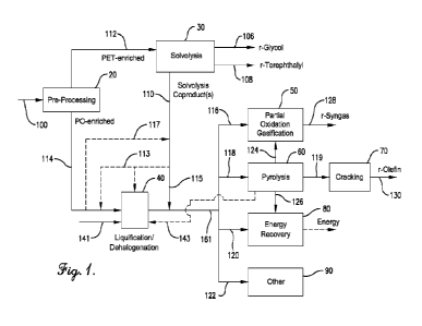
example, these conventional recycling processes can require high operation
costs, specifically in terms of energy consumption, that may offset any
financial
benefit of utilizing waste plastics as a feedstock. Thus, there exists a need
for
an efficient and economical chemical recycling method for breaking down waste
plastics.
[0003] Waste plastics often contain halogens (e.g., chlorine in
polyvinylchloride), which can be problematic in facilities used to pyrolyze,
gasify, crack, and/or combust waste plastics. Halogens are known to cause
corrosion of equipment and conduits used to process halogen-containing
streams.
Although certain metallurgies are resistant to corrosion from
halogens, implementation of such metallurgies can be cost prohibitive, both
for
newly constructed facilities and/or for retrofitting of existing facilities.
[0004]
Additionally, although various methods are known for removing
halogens from streams in conventional chemical processing plants, such
halogen removal methods are ineffective and/or cost prohibitive when applied
1
CA 03174737 2022- 10-5
WO 2021/211517
PCT/US2021/026987
to facilities for pyrolyzing, gasifying, cracking, and/or combusting waste
plastics.
SUMMARY
[0005] In one aspect, the present technology concerns a waste plastic
dehalogenation process. Generally, the process comprises: (a) liquefying solid
waste plastic to produce a liquefied waste plastic; (b) sparging a stripping
gas
into the liquefied waste plastic to produce a multi-phase mixture; and (c)
disengaging a gaseous phase from a liquid phase of the multi-phase mixture to
thereby provide a halogen-enriched gaseous material and a halogen-depleted
liquefied waste plastic.
[0006] In one aspect, the present technology concerns a
waste plastic
dehalogenation process. Generally, the process comprises: (a) introducing
solid waste plastic into a melt tank; (b) removing molten waste plastic from
the
melt tank to thereby provide a removed molten waste plastic; (c) heating at
least
a portion of the removed molten waste plastic in a heat exchanger to thereby
provide a heated molten waste plastic; and (d) disengaging a halogen-enriched
gaseous material from the heated molten waste plastic to thereby provide a
heated halogen-depleted molten waste plastic.
[0007] In one aspect, the present technology concerns a waste plastic
dehalogenation process. Generally, the process comprises: (a) liquefying solid
waste plastic in a melt tank in the presence of at least one dissolution
solvent
to produce a liquefied waste plastic, wherein the dissolution solvent
comprises
a pyrolysis oil; and (b) separating the liquefied waste plastic into a halogen-
enriched gaseous material and a halogen-depleted liquefied waste plastic.
[0008] In one aspect, the present technology concerns a
waste plastic
dehalogenation system. Generally, the system comprises: (a) a liquification
system for at least partially liquifying a solid waste plastic into a
liquified waste
plastic; (b) a halogen stripper configured to receive at least a portion of
the
liquified waste plastic and sparge a stripping gas into the liquified waste
plastic
to thereby form a multi-phase mixture; and (c) a disengagement vessel
2
CA 03174737 2022- 10-5
WO 2021/211517
PCT/US2021/026987
configured to receive the multi-phase mixture and disengage a gaseous phase
from a liquid phase of the multi-phase mixture to thereby provide a halogen-
enriched gaseous material and a halogen-depleted molten waste plastic.
[0009] In one aspect, the present technology concerns a
waste plastic
dehalogenation system. Generally, the system comprises: (a) a melt tank for
at least partially liquefying a solid waste plastic into a molten waste
plastic; (b)
a heat exchanger configured to receive at least a portion of the molten waste
plastic and heat at least a portion of the molten waste plastic to thereby
provide
a heated molten waste plastic; and (c) a disengagement vessel configured to
receive the heated molten waste plastic and disengage a gaseous phase from
a liquid phase of the heated molten waste plastic to thereby provide a halogen-
enriched gaseous material and a halogen-depleted molten waste plastic.
[0010] In one aspect, the present technology concerns a
chemical recycling
process. Generally, the process comprises: (a) subjecting a solid waste
plastic
to a viscosity reducing treatment to thereby provide a liquefied waste plastic
having a viscosity of less than 800 poise at 350 C and 10 radians/s; (b)
introducing at least a portion of the liquefied waste plastic into a pyrolysis
film
reactor; and (c) converting at least a portion of the liquefied waste plastic
in the
pyrolysis film reactor into a pyrolysis effluent comprising a pyrolysis gas.
[0011] In one aspect, the present technology concerns a chemical recycling
process. Generally, the process comprises: (a) separating a solid waste
plastic
feed into a polyolefin-enriched stream and a polyolefin-depleted stream; (b)
liquefying the polyolefin-enriched stream to thereby provide a liquefied waste
plastic; (c) introducing at least a portion of the liquefied waste plastic
into a
pyrolysis film reactor; and (d) converting at least a portion of the liquefied
waste
plastic in the pyrolysis film reactor into a pyrolysis effluent comprising a
pyrolysis gas.
[0012] In one aspect, the present technology concerns a
chemical recycling
process. Generally, the process comprises: (a) liquefying at least one solid
waste plastic to form a liquefied waste plastic; (b) removing one or more
halogens from the liquefied waste plastic to thereby form a halogen-depleted
3
CA 03174737 2022- 10-5
WO 2021/211517
PCT/US2021/026987
liquefied waste plastic; (c) introducing at least a portion of the halogen-
depleted
liquefied waste plastic into a pyrolysis film reactor; and (d) converting at
least a
portion of the halogen-depleted liquefied waste plastic in the pyrolysis film
reactor into a pyrolysis effluent comprising a pyrolysis gas.
[0013] In one aspect, the present technology concerns a chemical recycling
process. Generally, the process comprises: (a) liquefying solid waste plastic
in
a melt tank to produce a molten waste plastic; (b) subjecting the molten waste
plastic to at least one of the following steps ¨ (i) sparging a stripping gas
into
the molten waste plastic to produce a multi-phase mixture and (ii) heating at
least a portion of the molten waste plastic in a heat exchanger outside of the
melt tank to thereby provide a heated molten waste plastic; (c) disengaging a
gaseous phase from a liquid phase of the multi-phase mixture and/or the heated
molten waste plastic to thereby provide a halogen-enriched gaseous material
and a halogen-depleted molten waste plastic; (d) introducing the halogen-
depleted molten waste plastic into a pyrolysis film reactor; and (e)
converting at
least a portion of the liquefied waste plastic in the pyrolysis film reactor
into a
pyrolysis effluent comprising a pyrolysis gas.
[0014] In one aspect, the present technology concerns a
chemical recycling
process. Generally, the process comprises: (a) providing a liquefied waste
plastic; (b) introducing at least a portion of the liquefied waste plastic
into a
pyrolysis film reactor comprising a plurality of stationary film-generating
structures and operating at a temperature of at least 525 C; and (c) flowing
at
least a portion of the liquefied waste plastic downwardly along the stationary
film-generating structures to thereby pyrolyze the liquefied waste plastic and
form a pyrolysis effluent comprising a pyrolysis gas.
[0015] In one aspect, the present technology concerns a
chemical recycling
process. Generally, the process comprises: (a) providing a liquefied waste
plastic; (b) introducing at least a portion of the liquefied waste plastic
into an
upflow pyrolysis film reactor comprising a plurality of stationary film-
generating
structures; and (c) flowing at least a portion of the liquefied waste plastic
4
CA 03174737 2022- 10-5
WO 2021/211517
PCT/US2021/026987
upwardly along the stationary film-generating structures to thereby pyrolyze
the
liquefied waste plastic and form a pyrolysis effluent comprising a pyrolysis
gas.
[0016] In one aspect, the present technology concerns a
chemical recycling
facility. Generally, the facility comprises: (a) a waste plastic liquification
system
for liquefying at least one solid waste plastic, wherein the waste plastic
melting
system comprises a halogen removal system for removing one or more
halogens from the molten waste plastic thereby providing a halogen-depleted
molten waste plastic; and (b) a pyrolysis film reactor connected in fluid
communication with the waste plastic melting system and configured to receive
at least a portion of the halogen-depleted molten waste plastic and convert at
least a portion of the halogen-depleted molten waste plastic to pyrolysis
effluent
comprising a pyrolysis gas.
[0017] In one aspect, the present technology concerns a
chemical recycling
process. Generally, the process comprises: (a) liquefying at least one solid
waste plastic in the presence of a dissolution solvent to form a liquefied
waste
plastic, wherein the dissolution solvent comprises a pyrolysis oil; (b)
introducing
at least a portion of said liquefied waste plastic into a pyrolysis film
reactor; and
(c) converting at least a portion of said liquefied waste plastic in the
pyrolysis
film reactor into a pyrolysis effluent comprising a pyrolysis gas.
[0018] In one aspect, the present technology concerns a chemical recycling
process. Generally, the chemical recycling process comprises: (a) liquefying
at least one solid waste plastic to form a liquefied waste plastic; (b)
introducing
at least a portion of the liquefied waste plastic into a partial oxidation
(PDX)
gasifier; and (c) converting at least a portion of the liquefied waste plastic
in the
PDX gasifier into a syngas composition.
[0019] In one aspect, the present technology concerns a
chemical recycling
process. Generally, the chemical recycling process comprises: (a) liquefying
at least one solid waste plastic in a melt tank to form a molten waste
plastic; (b)
removing one or more halogens from the molten waste plastic to form a
halogen-depleted molten waste plastic; (c) introducing at least a portion of
the
halogen-depleted molten waste plastic into a partial oxidation (PDX) gasifier;
5
CA 03174737 2022- 10-5
WO 2021/211517
PCT/US2021/026987
and (d) converting at least a portion of the halogen-depleted molten waste
plastic in the PDX gasifier into a syngas composition.
[0020] In one aspect, the present technology concerns a
chemical recycling
facility. Generally, the chemical recycling facility comprises: (a) a waste
plastic
liquification system for liquefying at least one solid waste plastic and
forming a
liquefied waste plastic; and (b) a partial oxidation (PDX) gasifier connected
in
fluid communication with the plastic liquification system and configured to
receive at least a portion of the liquefied waste plastic and convert at least
a
portion of the liquefied waste plastic to a syngas composition.
[0021] In one aspect, the present technology concerns a chemical recycling
facility. Generally, the chemical recycling facility comprises: (a) a waste
plastic
melting system for liquefying at least one solid waste plastic and forming a
molten waste plastic, wherein the waste plastic melting system comprises a
dehalogenation system for removing one or more halogens from the molten
waste plastic thereby providing a halogen-depleted molten waste plastic; and
(b) a partial oxidation (PDX) gasifier connected in fluid communication with
the
waste plastic melting system and configured to receive at least a portion of
the
halogen-depleted molten waste plastic and convert at least a portion of the
halogen-depleted molten waste plastic to a syngas composition.
BRIEF DESCRIPTION OF THE FIGURES
[0022] Embodiments of the present invention are described
herein with
reference to the following drawing figures, wherein:
[0023] FIG. 1 depicts an exemplary chemical recycling
facility;
[0024] FIG. 2 depicts an exemplary separation zone of a preprocessing
facility;
[0025] FIG. 3 depicts an exemplary solvolysis facility;
[0026] FIG. 4 depicts an exemplary recycling facility with a
liquification melt
tank system;
[0027] FIG. 5 depicts an exemplary melt tank liquification system according
to one embodiment;
6
CA 03174737 2022- 10-5
WO 2021/211517
PCT/US2021/026987
[0028] FIG. 6 depicts an exemplary melt tank liquification
system according
to one embodiment;
[0029] FIG. 7 depicts an exemplary melt tank liquification
system according
to one embodiment;
[0030] FIG. 8 depicts an exemplary melt tank liquification system according
to one embodiment;
[0031] FIG. 9 depicts an exemplary melt tank liquification
system according
to one embodiment;
[0032] FIG. 10 depicts an exemplary melt tank liquification
system according
to one embodiment;
[0033] FIG. 11 depicts an exemplary external stripper for
the liquification
system;
[0034] FIG. 12 depicts an exemplary external stripper for
the liquification
system;
[0035] FIG. 13 depicts an exemplary disengagement vessel for the
liquification system;
[0036] FIG. 14 depicts an exemplary disengagement vessel for
the
liquification system;
[0037] FIG. 15 depicts an exemplary pyrolysis facility with
a liquification
system and pyrolysis film reactor;
[0038] FIG. 16 depicts an exemplary falling film pyrolysis
reactor;
[0039] FIG. 17 depicts exemplary tube perturbances for a
falling film
pyrolysis reactor;
[0040] FIG. 18 depicts exemplary tube perturbances for a
falling film
pyrolysis reactor;
[0041] FIG. 19 depicts an exemplary upflow film pyrolysis
reactor;
[0042] FIG. 20 depicts an exemplary cracking facility;
[0043] FIG. 21 provides a schematic diagram of a cracker
furnace;
[0044] FIG. 22 depicts an exemplary partial oxidation
gasification facility for
converting waste plastic;
[0045] FIG. 23 depicts an exemplary partial oxidation
gasification reactor;
7
CA 03174737 2022- 10-5
WO 2021/211517
PCT/US2021/026987
[0046] FIG. 24 depicts an exemplary injector for a partial
oxidation
gasification reactor;
[0047] FIG. 25 depicts the reactor configuration used for
Example 6; and
[0048] FIG. 26 provides a schematic demonstrating
"separation efficiency."
DETAILED DESCRIPTION
[0049] We have discovered an effective and efficient halogen
removal
technique for use in chemical recycling facilities. More particularly, we have
discovered a system that disengages gaseous halogens from liquified waste
plastic, prior to introducing the liquified waste plastic into a reaction step
(e.g.,
pyrolysis, gasification, cracking, or combusting) of a chemical recycling
facility.
[0050] When a numerical sequence is indicated, it is to be
understood that
each number is modified the same as the first number or last number in the
numerical sequence or in the sentence, e.g., each number is "at least," or "up
to" or "not more than" as the case may be; and each number is in an "or"
relationship. For example, "at least 10, 20, 30, 40, 50, 75 wt.%..." means the
same as "at least 10 wt.%, or at least 20 wt.%, or at least 30 wt.%, or at
least
40 wt.%, or at least 50 wt.%, or at least 75 wt.%," etc.; and "not more than
90
wt.%, 85, 70, 60..." means the same as "not more than 90 wt.%, or not more
than 85 wt.%, or not more than 70 wt.%...." etc.; and "at least 1%, 2%, 3%,
4%,
5%, 6%, 7%, 8%, 9% or 10% by weight..." means the same as "at least 1 wt.%,
or at least 2 wt.%, or at least 3 wt.% ..." etc.; and "at least 5, 10, 15, 20
and/or
not more than 99, 95, 90 weight percent" means the same as "at least 5 wt.%,
or at least 10 wt.%, or at least 15 wt.% or at least 20 wt.% and/or not more
than
99 wt.%, or not more than 95 wt.%, or not more than 90 weight percent..." etc.
[0051] All concentrations or amounts are by weight unless
otherwise stated.
Overall Chemical Recycling Facility
[0052] Turning now to FIG. 1, the main steps of a process
for chemically
recycling waste plastic in a chemical recycling facility 10 are shown. It
should
be understood that FIG. 1 depicts one exemplary embodiment of the present
8
CA 03174737 2022- 10-5
WO 2021/211517
PCT/US2021/026987
technology. Certain features depicted in FIG. 1 may be omitted and/or
additional features described elsewhere herein may be added to the system
depicted in FIG. 1.
[0053]
As shown in FIG. 1, these steps generally include a pre-processing
step/facility 20, and at least one (or at least two or more) of a solvolysis
step/facility 30, a partial oxidation (PDX) gasification step/facility 50, a
pyrolysis
step/facility 60, a cracking step/facility 70, and an energy recovery
step/facility
80. Optionally, in an embodiment or in combination with any embodiment
mentioned herein, these steps may also include one or more other steps, such
as, direct sale or use, landfilling, separation, and solidification, one or
more of
which is represented in FIG. 1 by block 90. Although shown as including all of
these steps or facilities, it should be understood that a chemical recycling
process and facility according to one or more embodiments of the present
technology can include at least two, three, four, five, or all of these
steps/facilities in various combinations for the chemical recycling of plastic
waste and, in particular, mixed plastic waste. Chemical recycling processes
and facilities as described herein may be used to convert waste plastic to
recycle content products or chemical intermediates used to form a variety of
end use materials.
The waste plastic fed to the chemical recycling
facility/process can be mixed plastic waste (MPW), pre-sorted waste plastic,
and/or pre-processed waste plastic.
[0054]
As used herein, the term "chemical recycling" refers to a waste plastic
recycling process that includes a step of chemically converting waste plastic
polymers into lower molecular weight polymers, oligomers, monomers, and/or
non-polymeric molecules (e.g., hydrogen and carbon monoxide) that are useful
by themselves and/or are useful as feedstocks to another chemical production
process or processes. A "chemical recycling facility," is a facility for
producing
a recycle content product via chemical recycling of waste plastic. As used
herein, the terms "recycle content" and "r-content" mean being or comprising a
composition that is directly and/or indirectly derived from waste plastic.
9
CA 03174737 2022- 10-5
WO 2021/211517
PCT/US2021/026987
[0055] As used herein, the term "directly derived" 'means
having at least one
physical component originating from waste plastic, while "indirectly derived"
means having an assigned recycle content that i) is attributable to waste
plastic,
but ii) that is not based on having a physical component originating from
waste
plastic.
[0056] Chemical recycling facilities are not mechanical
recycling facilities.
As used herein, the terms "mechanical recycling" and "physical recycling"
refer
to a recycling process that includes a step of melting waste plastic and
forming
the molten plastic into a new intermediate product (e.g., pellets or sheets)
and/or a new end product (e.g., bottles). Generally, mechanical recycling does
not substantially change the chemical structure of the plastic being recycled.
In
one embodiment or in combination with any of the mentioned embodiments,
the chemical recycling facilities described herein may be configured to
receive
and process waste streams from and/or that are not typically processable by a
mechanical recycling facility.
[0057] Although described herein as being part of a single
chemical
recycling facility, it should be understood that one or more of the
preprocessing
facility 20, the solvolysis facility 30, the pyrolysis facility 60, the
cracking facility
70, the partial oxidation (PDX) gasification facility 50, and the energy
recovery
facility 80, or any of the other facility 90 such as solidification or
separation, may
be located in a different geographical location and/or be operated by a
different
commercial entity. Each of the preprocessing facility 20, the solvolysis
facility
30, the pyrolysis facility 60, the cracking facility 70, the partial oxidation
(PDX)
gasification facility 50, the energy recovery facility 80, or any other
facility 90
may be operated by the same entity, while, in other cases, one or more of the
preprocessing facility 20, the solvolysis facility 30, the pyrolysis facility
60, the
cracking facility 70, the partial oxidation (PDX) gasification facility 50, a
solidification facility, the energy recovery facility 80, and one or more
other
facility 90 such as separation or solidification, may be operated by a
different
commercial entity.
CA 03174737 2022- 10-5
WO 2021/211517
PCT/US2021/026987
[0058] In an embodiment or in combination with any
embodiment mentioned
herein, the chemical recycling facility 10 may be a commercial-scale facility
capable of processing significant volumes of mixed plastic waste. As used
herein, the term "commercial scale facility" refers to a facility having an
average
annual feed rate of at least 500 pounds per hour, averaged over one year. The
average feed rate to the chemical recycling facility (or to any one of the
preprocessing facility 20, the solvolysis facility 30, the pyrolysis facility
60, the
cracking facility 70, the PDX gasification facility 50, the energy recovery
facility
80, and any other facility 90) can be at least 750, at least 1,000, at least
1,500,
at least 2,000, at least 2,500, at least 3,000, at least 3,500, at least
4,000, at
least 4,500, at least 5,000, at least 5,500, at least 6,000, at least 6,500,
at least
7,500, at least 10,000, at least 12,500, at least 15,000, at least 17,500, at
least
20,000, at least 22,500, at least 25,000, at least 27,500, at least 30,000 or
at
least 32,500 pounds per hour and/or not more than 1,000,000, not more than
750,000, not more than 500,000, not more than 450,000, not more than
400,000, not more than 350,000, not more than 300,000, not more than
250,000, not more than 200,000, not more than 150,000, not more than
100,000, not more than 75,000, not more than 50,000, or not more than 40,000
pounds per hour. When a facility includes two or more feed streams, the
average annual feed rate is determined based on the combined weight of the
feed streams.
[0059] Additionally, it should be understood that each of
the preprocessing
facility 20, the solvolysis facility 30, the pyrolysis facility 60, the
cracking facility
70, the PDX gasification facility 50, the energy recovery facility 80, and any
other facility 90 may include multiple units operating in series or parallel.
For
example, the pyrolysis facility 60 may include multiple pyrolysis
reactors/units
operating in parallel and each receiving a feed comprising waste plastic. When
a facility is made up of multiple individual units, the average annual feed
rate to
the facility is calculated as the sum of the average annual feed rates to all
of
the common types of units within that facility.
11
CA 03174737 2022- 10-5
WO 2021/211517
PCT/US2021/026987
[0060] Additionally, in an embodiment or in combination with any
embodiment mentioned herein, the chemical recycling facility 10 (or any one of
the preprocessing facility 20, the solvolysis facility 30, the pyrolysis
facility 60,
the cracking facility 70, the PDX gasification facility 50, the energy
recovery
facility 80, and any other facility 90) may be operated in a continuous
manner.
Additionally, or in the alternative, at least a portion of the chemical
recycling
facility 10 (or any of the preprocessing facility 20, the solvolysis facility
30, the
pyrolysis facility 60, the cracking facility 70, the PDX gasification facility
50, the
energy recovery facility 80, and any other facility 90) may be operated in a
batch
or semi-batch manner. In some cases, the facility may include a plurality of
tanks between portions of a single facility or between two or more different
facilities to manage inventory and ensure consistent flow rates into each
facility
or portion thereof.
[0061] In addition, two or more of the facilities shown in
FIG. 1 may also be
co-located with one another. In an embodiment or in combination with any
embodiment mentioned herein, at least two, at least three, at least four, at
least
five, at least six, or all of the facilities may be co-located. As used
herein, the
term "co-located" refers to facilities in which at least a portion of the
process
streams and/or supporting equipment or services are shared between the two
facilities. When two or more of the facilities shown in FIG. 1 are co-located,
the
facilities may meet at least one of the following criteria (i) through (v):
(i) the
facilities share at least one non-residential utility service; (ii) the
facilities share
at least one service group; (iii) the facilities are owned and/or operated by
parties that share at least one property boundary; (iv) the facilities are
connected by at least one conduit configured to carry at least one process
material (e.g., solid, liquid and/or gas fed to, used by, or generated in a
facility)
from one facility to another; and (v) the facilities are within 40, within 35,
within
30, within 20, within 15, within 12, within 10, within 8, within 5, within 2,
or within
1 mile of one another, measured from their geographical center. At least one,
at least two, at least three, at least four, or all of the above statements
(i) through
(v) may be true.
12
CA 03174737 2022- 10-5
WO 2021/211517
PCT/US2021/026987
[0062]
Regarding (i), examples of suitable utility services include, but are
not limited to, steam systems (co-generation and distribution systems),
cooling
water systems, heat transfer fluid systems, plant or instrument air systems,
nitrogen systems, hydrogen systems, non-residential electrical generation and
distribution, including distribution above 8000V,
non-residential
wastewater/sewer systems, storage facilities, transport lines, flare systems,
and combinations thereof.
[0063]
Regarding (i), examples of suitable utility services include, but are
not limited to, steam systems (co-generation and distribution systems),
cooling
water systems, heat transfer fluid systems, plant or instrument air systems,
nitrogen systems, hydrogen systems, non-residential electrical generation and
distribution, including distribution above
8000V, non-residential
wastewater/sewer systems, storage facilities, transport lines, flare systems,
and combinations thereof.
[0064]
Regarding (ii), examples of service groups and facilities include, but
are not limited to, emergency services personnel (fire and/or medical), a
third-
party vendor, a state or local government oversight group, and combinations
thereof. Government oversight groups can include, for example, regulatory or
environmental agencies, as well as municipal and taxation agencies at the
city,
county, and state level.
[0065]
Regarding (iii), the boundary may be, for example, a fence line, a
property line, a gate, or common boundaries with at least one boundary of a
third-party owned land or facility.
[0066]
Regarding (iv), the conduit may be a fluid conduit that carries a gas,
a liquid, a solid/liquid mixture (e.g., slurry), a solid/gas mixture (e.g.,
pneumatic
conveyance), a solid/liquid/gas mixture, or a solid (e.g., belt conveyance).
In
some cases, two units may share one or more conduits selected from the above
list. Fluid conduits may be used to transport process streams or utilities
between the two units. For example, an outlet of one facility (e.g., the
solvolysis
facility 30) may be fluidly connected via a conduit with an inlet of another
facility
(e.g., the PDX gasification facility 50). In some cases, an interim storage
13
CA 03174737 2022- 10-5
WO 2021/211517
PCT/US2021/026987
system for the materials being transported within the conduit between the
outlet
of one facility and the inlet of another facility may be provided. The interim
storage system may comprise, for example, one or more tanks, vessels (open
or closed), buildings, or containers that are configured to store the material
carried by the conduit. In some cases, the interim storage between the outlet
of one facility and the inlet of another can be not more than 90, not more
than
75, not more than 60, not more than 40, not more than 30, not more than 25,
not more than 20, not more than 15, not more than 10, not more than 5, not
more than 2 days or not more than 1 day.
[0067] Turning
again to FIG. 1, a stream 100 of waste plastic, which can be
mixed plastic waste (MPW), may be introduced into the chemical recycling
facility 10. As used herein, the terms "waste plastic" and "plastic waste"
refer
to used, scrap, and/or discarded plastic materials, such as plastic materials
typically sent to a landfill. The waste plastic stream 100 fed to the chemical
recycling facility 10 may include unprocessed or partially processed waste
plastic. As used herein, the term "unprocessed waste plastic" means waste
plastic that has not be subjected to any automated or mechanized sorting,
washing, or comminuting. Examples of unprocessed waste plastic include
waste plastic collected from household curbside plastic recycling bins or
shared
community plastic recycling containers. As used herein, the term "partially
processed waste plastic" means waste plastic that has been subjected to at
least one automated or mechanized sorting, washing, or comminuting step or
process. Partially processed waste plastics may originate from, for example,
municipal recycling facilities (MRFs) or reclaimers. When partially processed
waste plastic is provided to the chemical recycling facility 10, one or more
preprocessing steps may be skipped. Waste plastic may comprise at least one
of post-industrial (or pre-consumer) plastic and/or post-consumer plastic.
[0068]
As used herein, the terms "mixed plastic waste" and "MPW" refer to
a mixture of at least two types of waste plastics including, but not limited
to the
following plastic types: polyethylene terephthalate (PET), one or more
polyolefins (PO), and polyvinylchloride (PVC).
In an embodiment or in
14
CA 03174737 2022- 10-5
WO 2021/211517
PCT/US2021/026987
combination with any embodiment mentioned herein, MPW includes at least
two distinct types of plastic, with each type of plastic being present in an
amount
of at least 1, at least 2, at least 5, at least 10, at least 15, or at least
20 weight
percent, based on the total weight of plastic in the MPW.
[0069] In an embodiment or in combination with any embodiment mentioned
herein, MPW comprises at least 1, at least 2, at least 5, at least 10, at
least 15,
at least 20, at least 25, at least 30, at least 35, at least 40, at least 45,
at least
50, at least 55, at least 60, at least 65, at least 70, at least 75, at least
80, at
least 85, at least 90, at least 95, or at least 99 weight percent PET and/or
at
least 1, at least 2, at least 5, at least 10, at least 15, or at least 20
weight percent
PO, based on the total weight of plastic in the MPW. In one embodiment or
more embodiments, MPW may also include minor amounts of one or more
types of plastic components other than PET and PO (and optionally PVC) that
total less than 50, less than 45, less than 40, less than 35, less than 30,
less
than 25, less than 20, less than 15, less than 10, less than 5, less than 2,
or
less than 1 weight percent, based on the total weight of plastic in the MPW.
[0070] In an embodiment or in combination with any
embodiment mentioned
herein, the MPW comprises at least 20, at least 25, at least 30, at least 35,
at
least 40, at least 45, at least 50, at least 55, at least 60, at least 65, at
least 70,
at least 75, at least 80, at least 85, at least 90, or at least 95 weight
percent
PET, based on the total weight of the stream. Alternatively, or in addition,
the
MPW comprises not more than 99.9, not more than 99, not more than 97, not
more than 92, not more than 90, not more than 85, not more than 80, not more
than 75, not more than 70, not more than 65, not more than 60, not more than
55, not more than 50, not more than 45, not more than 40, not more than 35,
not more than 30, not more than 25, not more than 20, not more than 15, not
more than 10, or not more than 5 weight percent PET, based on the total weight
of the stream.
[0071] The MPW stream can include non-PET components in an amount of
at least 0.1, at least 0.5, at least 1, at least 2, at least 5, at least 7, at
least 10,
at least 15, at least 20, at least 25, at least 30, or at least 35 and/or not
more
CA 03174737 2022- 10-5
WO 2021/211517
PCT/US2021/026987
than 80, not more than 75, not more than 70, not more than 65, not more than
60, not more than 55, not more than 50, not more than 45, not more than 40,
not more than 35, not more than 30, not more than 25, not more than 20, not
more than 15, not more than 10, or not more than 7 weight percent, based on
the total weight of the stream. Non-PET components can be present in an
amount between 0.1 and 50 weight percent, 1 and 20 weight percent, or 2 and
weight percent, based on the total weight of the stream. Examples of such
non-PET components can include, but are not limited to, ferrous and non-
ferrous metals, inerts (such as rocks, glass, sand, etc.), plastic inerts
(such as
10 titanium dioxide, silicon dioxide, etc.), olefins, adhesives,
compatibilizers,
biosludge, cellulosic materials (such as cardboard, paper, etc.), and
combinations thereof.
[0072] In an embodiment or in combination with any
embodiment
mentioned herein, all or a portion of the MPW can originate from a municipal
source or comprise municipal waste. The municipal waste portion of the MPW
can include, for example, PET in an amount of from 45 to 95 weight percent,
50 to 90 weight percent, or 55 to 85 weight percent, based on the total weight
of the municipal waste stream (or portion of the stream).
[0073] In an embodiment or in combination with any
embodiment mentioned
herein, all or a portion of the MPW can originate from a municipal recycling
facility (MRF) and may include, for example, PET in an amount of from 65 to
99.9 weight percent, 70 to 99 weight percent, or 80 to 97 weight percent,
based
on the total weight of the stream. The non-PET components in such streams
may include, for example, other plastics in an amount of at least 1, at least
2,
at least 5, at least 7, or at least 10 weight percent and/or not more than 25,
not
more than 22, not more than 20, not more than 15, not more than 12, or not
more than 10 weight percent, based on the total weight of the stream, or such
may be present in an amount in the range of from 1 to 22 weight percent, 2 to
15 weight percent, or 5 to 12 weight percent, based on the total weight of the
stream. In an embodiment or in combination with any embodiment mentioned
herein, the non-PET components can include other plastics in an amount in the
16
CA 03174737 2022- 10-5
WO 2021/211517
PCT/US2021/026987
range of from 2 to 35 weight percent, 5 to 30 weight percent, or 10 to 25
weight
percent, based on the total weight of the stream, particularly when, for
example,
the MPW includes colored sorted plastics.
[0074]
In an embodiment or in combination with any embodiment mentioned
herein, all or a portion of the MPW can originate from a reclaimer facility
and
may include, for example, PET in an amount of from 85 to 99.9 weight percent,
90 to 99.9 weight percent, or 95 to 99 weight percent, based on the total
weight
of the stream. The non-PET components in such streams may include, for
example, other plastics in an amount of at least 1, at least 2, at least 5, at
least
7, or at least 10 weight percent and/or not more than 25, not more than 22,
not
more than 20, not more than 15, not more than 12, or not more than 10 weight
percent, based on the total weight of the stream, or such may be present in an
amount in the range of from 1 to 22 weight percent, 2 to 15 weight percent, or
5 to 12 weight percent, based on the total weight of the stream.
[0075] As used
herein, the term "plastic" may include any organic synthetic
polymers that are solid at 25 C and 1 atmosphere of pressure. In an
embodiment or in combination with any embodiment mentioned herein, the
polymers may have a number average molecular weight (Mn) of at least 75, or
at least 100, or at least 125, or at least 150, or at least 300, or at least
500, or
at least 1000, or at least 5,000, or at least 10,000, or at least 20,000, or
at least
30,000, or at least 50,000 or at least 70,000 or at least 90,000 or at least
100,000 or at least 130,000 Da!tons. The weight average molecular weight
(Mw) of the polymers can be at least 300, or at least 500, or at least 1000,
or at
least 5,000, or at least 10,000, or at least 20,000, or at least 30,000 or at
least
50,000, or at least 70,000, or at least 90,000, or at least 100,000, or at
least
130,000, or at least 150,000, or at least 300,000 Da!tons.
[0076]
Examples of suitable plastics can include, but are not limited to,
aromatic and aliphatic polyesters, polyolefins, polyvinyl chloride (PVC),
polystyrene, polytetrafluoroethylene,
acrylobutadienestyrene (ABS),
cellulosics, epoxides, polyamides, phenolic resins, polyacetal,
polycarbonates,
polyphenylene-based alloys, poly(methyl methacrylate), styrene-containing
17
CA 03174737 2022- 10-5
WO 2021/211517
PCT/US2021/026987
polymers, polyurethane, vinyl-based polymers, styrene acrylonitrile,
thermoplastic elastomers other than tires, and urea containing polymers and
melamines.
[0077] Examples of polyesters can include those having
repeating aromatic
or cyclic units such as those containing a repeating terephthalate,
isophthalate,
or naphthalate units such as PET, modified PET, and PEN, or those containing
repeating furanate repeating units. Polyethylene terephthalate (PET) is also
an
example of a suitable polyester. As used herein, "PET" or "polyethylene
terephthalate" refers to a homopolymer of polyethylene terephthalate, or to a
polyethylene terephthalate modified with one or more acid and/or glycol
modifiers and/or containing residues or moieties of other than ethylene glycol
and terephthalic acid, such as isophthalic acid, 1,4-cyclohexanedicarboxylic
acid, diethylene glycol, 2,2,4,4-tetramethy1-1,3-cyclobutanediol (TMCD),
cyclohexanedimethanol (CHDM), propylene glycol, isosorbide, 1,4-butanediol,
1,3-propane diol, and/or neopentyl glycol (NPG).
[0078] Also included within the definition of the terms "PET" and
"polyethylene terephthalate" are polyesters having repeating terephthalate
units (whether or not they contain repeating ethylene glycol-based units) and
one or more residues or moieties of a glycol including, for example, TMCD,
CHDM, propylene glycol, or NPG, isosorbide, 1,4-butanediol, 1,3-propane diol,
and/or diethylene glycol, or combinations thereof. Examples of polymers with
repeat terephthalate units can include, but are not limited to, polypropylene
terephthalate, polybutylene terephthalate, and copolyesters thereof. Examples
of aliphatic polyesters can include, but are not limited to, polylactic acid
(PLA),
polyglycolic acid, polycaprolactones, and polyethylene adipates. The polymer
may comprise mixed aliphatic-aromatic copolyesters including, for example,
mixed terephthalates/adipates.
[0079] In an embodiment or in combination with any
embodiment mentioned
herein, the waste plastic may comprise at least one type of plastic that has
repeat terephthalate units with such a plastic being present in an amount of
at
least 1, at least 2, at least 5, at least 10, at least 15, at least 20, at
least 25, or
18
CA 03174737 2022- 10-5
WO 2021/211517
PCT/US2021/026987
at least 30 and/or not more than 45, not more than 40, not more than 35, not
more than 30, not more than 25, not more than 20, not more than 15, not more
than 10, not more than 5, or not more than 2 weight percent, based on the
total
weight of the stream, or it can be present in the range of from 1 to 45 weight
percent, 2 to 40 weight percent, or 5 to 40 weight percent, based on the total
weight of the stream. Similar amounts of copolyesters having multiple
cyclohexane dimethanol moieties, 2,2,4,4-tetramethy1-1,3-cyclobutanediol
moieties, or combinations thereof may also be present.
[0080] In an embodiment or in combination with any
embodiment mentioned
herein, the waste plastic may comprise at least one type of plastic that has
repeat terephthalate units with such a plastic being present in an amount of
at
least 30, at least 35, at least 40, at least 45, at least 50, at least 55, at
least 60,
at least 65, at least 70, at least 75, at least 80, at least 85, or at least
90 and/or
not more than 99.9, not more than 99, not more than 97, not more than 95, not
more than 90, or not more than 85 weigh percent, based on the total weight of
the stream, or it can be present in the range of from 30 to 99.9 weight
percent,
50 to 99.9 weight percent, or 75 to 99 weight percent, based on the total
weight
of the stream.
[0081] In an embodiment of in combination with any
embodiment mentioned
herein, the waste plastic may comprise terephthalate repeat units in an amount
of at least 1, at least 5, at least 10, at least 15, at least 20, at least 25,
at least
30, at least 35, at least 40, or at least 45 and/or not more than 75, not more
than 72, not more than 70, not more than 60, or not more than 65 weight
percent, based on the total weight of the plastic in the waste plastic stream,
or
it may include terephthalate repeat units in an amount in the range of from 1
to
75 weight percent, 5 to 70 weight percent, or 25 to 75 weight percent, based
on
the total weight of the stream.
[0082] Examples of specific polyolefins may include low density
polyethylene (LDPE), high density polyethylene (HOPE), atactic polypropylene,
isotactic polypropylene, syndiotactic polypropylene, crosslinked polyethylene,
amorphous polyolefins, and the copolymers of any one of the aforementioned
19
CA 03174737 2022- 10-5
WO 2021/211517
PCT/US2021/026987
polyolefins. In an embodiment or in combination with any embodiment
mentioned herein, the waste plastic may include polymers including linear low-
density polyethylene (LLDPE), polymethylpentene, polybutene-1, and
copolymers thereof. In an embodiment or in combination with any embodiment
mentioned herein, the waste plastic may comprise flashspun high density
polyethylene.
[0083] The waste plastic may include thermoplastic polymers,
thermosetting
polymers, or combinations thereof. In an embodiment or in combination with
any embodiment mentioned herein, the waste plastic can include at least 0.1,
at least 1, at least 2, at least 5, at least 10, at least 15, at least 20, at
least 25,
or at least 30 and/or not more than 45, not more than 40, not more than 35,
not
more than 30, not more than 25, not more than 20, not more than 15, not more
than 10, not more than 5, or not more than 2 weight percent of one or more
thermosetting polymers, based on the total weight of the stream, or it can be
present in an amount of 0.1 to 45 weight percent, 1 to 40 weight percent, 2 to
35 weight percent, or 2 to 20 weight percent, based on the total weight of the
stream.
[0084] Alternatively, or in addition, the waste plastic may
include at least 0.1,
at least 1, at least 2, at least 5, at least 10, at least 15, at least 20, at
least 25,
or at least 30 and/or not more than 45, not more than 40, not more than 35,
not
more than 30, not more than 25, not more than 20, not more than 15, not more
than 10, not more than 5, or not more than 2 weight percent of cellulose
materials, based on the total weight of the stream, or it can be present in an
amount in the range of from 0.1 to 45 weight percent, 1 to 40 weight percent,
or 2 to 15 weight percent, based on the total weight of the stream. Examples
of cellulose materials may include cellulose acetate, cellulose diacetate,
cellulose triacetate, cellulose acetate propionate, cellulose acetate
butyrate, as
well as regenerated cellulose such as viscose. Additionally, the cellulose
materials can include cellulose derivatives having an acyl degree of
substitution
of less than 3, not more than 2.9, not more than 2.8, not more than 2.7, or
not
CA 03174737 2022- 10-5
WO 2021/211517
PCT/US2021/026987
more than 2.6 and/or at least 1.7, at least 1.8, or at least 1.9, or from 1.8
to 2.8,
or 1.7 to 2.9, or 1.9 to 2.9.
[0085] In an embodiment or in combination with any
embodiment mentioned
herein, the waste plastic may comprise STYROFOAM or expanded
polystyrene.
[0086] The waste plastic may originate from one or more of
several sources.
In an embodiment or in combination with any embodiment mentioned herein,
the waste plastic may originate from plastic bottles, diapers, eyeglass
frames,
films, packaging materials, carpet (residential, commercial, and/or
automotive),
textiles (clothing and other fabrics) and combinations thereof.
[0087] In an embodiment or in combination with any
embodiment mentioned
herein, the waste plastic (e.g., MPW) fed to the chemical recycling facility
may
include one or more plastics having or obtained from plastics having a resin
ID
code numbered 1-7 with the chasing arrow triangle established by the SPI. The
waste plastic may include one or more plastics that are not generally
mechanically recycled. Such plastics can include, but are not limited to,
plastics
with the resin ID code 3 (polyvinyl chloride), resin ID code 5
(polypropylene),
resin ID code 6 (polystyrene), and/or resin ID code 7 (other). In an
embodiment
or in combination with any embodiment mentioned herein, plastics having at
least 1, at least 2, at least 3, at least 4, or at least 5 of the resin ID
codes 3-7 or
3, 5, 6, 7, or a combination thereof may be present in the waste plastic in an
amount of at least 0.1, at least 0.5, at least 1, at least 2, at least 3, at
least 5, at
least 7, at least 10, at least 12, at least 15, at least 20, at least 25, at
least 30,
at least 35, or at least 40 and/or not more than 90, not more than 85, not
more
than 80, not more than 75, not more than 70, not more than 65, not more than
60, not more than 55, not more than 50, not more than 45, not more than 40,
or not more than 35 weight percent, based on the total weight of all plastics,
or
it could be in an amount of 0.1 to 90 weight percent, 1 to 75 weight percent,
or
2 to 50 weight percent, based on the total weight of plastics.
[0088] In an embodiment or in combination with any embodiment mentioned
herein, at least 5, at least 10, at least 15, at least 20, at least 25, at
least 30, or
21
CA 03174737 2022- 10-5
WO 2021/211517
PCT/US2021/026987
at least 35 and/or not more than 60, not more than 55, not more than 50, not
more than 45, not more than 40, not more than 35, not more than 30, not more
than 25, not more than 20, not more than 15, not more than 10, or not more
than 5 weight percent of the total plastic components in the waste plastic fed
to
the chemical recycling facility may comprise plastics not having a resin ID
code
3, 5, 6, and/or 7 (e.g., where a plastic is not classified). At least 0.1, at
least
0.5, at least 1, at least 2, at least 3, at least 4, at least 5, at least 10,
at least 15,
at least 20, at least 25, at least 30, or at least 35 and/or not more than 60,
not
more than 55, not more than 50, not more than 45, not more than 40, not more
than 35, not more than 30, not more than 25, not more than 20, not more than
15, not more than 10, or not more than 5 weight percent of the total plastic
components in the waste plastic fed to the chemical recycling facility 10 may
comprise plastics not having a resin ID code 4-7, or it can be in the range of
0.1
to 60 weight percent, 1 to 55 weight percent, or 2 to 45 weight percent, based
on the total weight of plastic components.
[0089] In an embodiment or in combination with any
embodiment mentioned
herein, the waste plastic (e.g., MPW) fed to the chemical recycling facility
may
comprise plastic that is not classified as resin ID codes 3-7 or ID codes 3,
5, 6,
or 7. The total amount of plastic not classified as resin ID code 3-7 or ID
codes
3, 5, 6, or 7 plastics in the waste plastic can be at least 0.1, at least 0.5,
at least
1, at least 2, at least 3, at least 4, at least 5, at least 10, at least 15,
at least 20,
at least 25, at least 30, at least 35, at least 40, at least 45, at least 50,
at least
55, at least 60, at least 65, at least 70, or at least 75 and/or not more than
95,
not more than 90, not more than 85, not more than 80, not more than 75, not
more than 70, not more than 65, not more than 60, not more than 55, not more
than 50, not more than 45, not more than 40, or not more than 35 weight
percent, based on the total weight of plastic in the waste plastic stream, or
it
can be in the range of from 0.1 to 95 weight percent, 0.5 to 90 weight
percent,
or 1 to 80 weight percent, based on the total weight of plastic in the waste
plastic
stream.
22
CA 03174737 2022- 10-5
WO 2021/211517
PCT/US2021/026987
[0090] In one embodiment or in combination with any of the
mentioned
embodiments, the MPW comprises plastics having or obtained from plastics
having at least 30, at least 35, at least 40, at least 45, at least 50, at
least 55,
at least 60, at least 65, at least 70, at least 75, at least 80, at least 85,
at least
90, at least 95, or at least 99 weight percent of at least one, at least two,
at least
three, or at least four different kinds of resin ID codes.
[0091] In one embodiment or in combination with any of the
mentioned
embodiments, the MPW comprises multi-component polymers. As used
herein, the term "multi-component polymers" refers to articles and/or
particulates comprising at least one synthetic or natural polymer combined
with,
attached to, or otherwise physically and/or chemically associated with at
least
one other polymer and/or non-polymer solid. The polymer can be a synthetic
polymer or plastic, such as PET, olefins, and/or nylons. The non-polymer solid
can be a metal, such as aluminum, or other non-plastic solids as described
herein. The multi-component polymers can include metalized plastics.
[0092] In one embodiment or in combination with any of the
mentioned
embodiments, the MPW comprises multi-component plastics in the form of
multi-layer polymers. As used herein, the term "multi-layer polymers" refers
to
multi-component polymers comprising PET and at least one other polymer
and/or non-polymer solid physically and/or chemically associated together in
two or more physically distinct layers. A polymer or plastic is considered a
multi-
layered polymer even though a transition zone may exist between two layers,
such as may be present in adhesively adhered layers or co-extruded layers. An
adhesive between two layers is not deemed to be a layer. The multi-layer
polymers may comprise a layer comprising PET and a one or more additional
layers at least one of which is a synthetic or natural polymer that is
different
from PET, or a polymer which has no ethylene terephthalate repeating units, or
a polymer which has no alkylene terephthalate repeating units (a "non-PET
polymer layer"), or other non-polymer solid.
[0093] Examples of non-PET polymer layers include nylons, polylactic acid,
polyolefins, polycarbonates, ethylene vinyl alcohol, polyvinyl alcohol, and/or
23
CA 03174737 2022- 10-5
WO 2021/211517
PCT/US2021/026987
other plastics or plastic films associated with PET-containing articles and/or
particulates, and natural polymers such as whey proteins. The multi-layer
polymers may include metal layers, such as aluminum, provided that at least
one additional polymer layer is present other than the PET layer. The layers
may be adhered with adhesive bonding or other means, physically adjacent
(i.e., articles pressed against the film), tackified (i.e., the plastics
heated and
stuck together), co-extruded plastic films, or otherwise attached to the PET-
containing articles.
The multi-layer polymers may comprise PET films
associated with articles containing other plastics in the same or similar
manner.
The MPW may comprise multi-component polymers in the form of PET and at
least one other plastic, such as polyolefins (e.g., polypropylene) and/or
other
synthetic or natural polymers, combined in a single physical phase. For
example, the MPW comprises a heterogenous mixture comprising a
compatibilizer, PET, and at least one other synthetic or natural polymer
plastic
(e.g., non-PET plastic) combined in a single physical phase. As used herein,
the term "compatibilizer" refers to an agent capable of combining at least two
otherwise immiscible polymers together in a physical mixture (i.e., blend).
[0094]
In one embodiment or in combination with any of the mentioned
embodiments, the MPW comprises not more than 20, not more than 10, not
more than 5, not more than 2, not more than 1, or not more than 0.1 weight
percent nylons, on a dry plastic basis. In one embodiment or in combination
with any of the mentioned embodiments, the MPW comprises from 0.01 to 20,
from 0.05 to 10, from 0.1 to 5, or from 1 to 2 weight percent nylons, on a dry
plastic basis.
[0095] In one
embodiment or in combination with any of the mentioned
embodiments, the MPW comprises not more than 40, not more than 20, not
more than 10, not more than 5, not more than 2, or not more than 1 weight
percent multi-component plastics, on a dry plastic basis. In one embodiment
or in combination with any of the mentioned embodiments, the MPW comprises
from 0.1 to 40, from 1 to 20, or from 2 to 10 weight percent multi-component
plastics, on a dry plastic basis. In one embodiment or in combination with any
24
CA 03174737 2022- 10-5
WO 2021/211517
PCT/US2021/026987
of the mentioned embodiments, the MPW comprises not more than 40, not
more than 20, not more than 10, not more than 5, not more than 2, or not more
than 1 weight percent multi-layer plastics, on a dry plastic basis. In one
embodiment or in combination with any of the mentioned embodiments, the
MPW comprises from 0.1 to 40, from 1 to 20, or from 2 to 10 weight percent
multi-layer plastics, on a dry plastic basis.
[0096] In one embodiment or in combination with any of the
mentioned
embodiments, the MPW feedstock to the chemical recycling facility 10 in stream
100 comprises not more than 20, not more than 15, not more than 12, not more
than 10, not more than 8, not more than 6, not more than 5, not more than 4,
not more than 3, not more than 2, or not more than 1 weight percent of
biowaste
materials, with the total weight of the MPW feedstock taken as 100 weight
percent on a dry basis. The MPW feedstock comprises from 0.01 to 20, from
0.1 to 10, from 0.2 to 5, or from 0.5 to 1 weight percent of biowaste
materials,
with the total weight of the MPW feedstock taken as 100 weight percent on a
dry basis. As used herein, the term "biowaste" refers to material derived from
living organisms or of organic origin. Exemplary biowaste materials include,
but are not limited to, cotton, wood, saw dust, food scraps, animals and
animal
parts, plants and plant parts, and manure.
[0097] In one embodiment or in combination with any of the mentioned
embodiments, the MPW feedstock comprises not more than 20, not more than
15, not more than 12, not more than 10, not more than 8, not more than 6, not
more than 5, not more than 4, not more than 3, not more than 2, or not more
than 1 weight percent of manufactured cellulose products, with the total
weight
of the MPW feedstock taken as 100 weight percent on a dry basis. The MPW
feedstock comprises from 0.01 to 20, from 0.1 to 10, from 0.2 to 5, or from
0.5
to 1 weight percent of manufactured cellulose products, with the total weight
of
the MPW feedstock taken as 100 weight percent on a dry basis. As used
herein, the term "manufactured cellulose products" refers to nonnatural (i.e.,
manmade or machine-made) articles, and scraps thereof, comprising cellulosic
CA 03174737 2022- 10-5
WO 2021/211517
PCT/US2021/026987
fibers. Exemplary manufactured cellulose products include, but are not limited
to, paper and cardboard.
[0098] In an embodiment or in combination with any
embodiment mentioned
herein, the waste plastic (e.g., MPW) fed to the chemical recycling facility
can
include at least 0.001, at least 0.01, at least 0.05, at least 0.1, or at
least 0.25
weight percent and/or not more than 10, not more than 5, not more than 4, not
more than 3, not more than 2, not more than 1, not more than 0.75, or not more
than 0.5 weight percent of polyvinyl chloride (PVC) based on the total weight
of
plastics in the waste plastic feed.
[0099] Additionally, or in the alternative, the waste plastic (e.g., MPW)
fed
to the chemical recycling facility can include at least 0.1, at least 1, at
least 2,
at least 4, or at least 6 weight percent and/or not more than 25, not more
than
15, not more than 10, not more than 5, or not more than 2.5 weight percent of
non-plastic solids. Non-plastic solids may include inert filler materials
(e.g.,
calcium carbonate, hydrous aluminum silicate, alumina trihydrate, calcium
sulfate), rocks, glass, and/or additives (e.g., thixotropes, pigments and
colorants, fire retardants, suppressants, UV inhibitors & stabilizers,
conductive
metal or carbon, release agents such as zinc stearate, waxes, and silicones).
[0100] In one embodiment or in combination with any of the
mentioned
embodiments, the MPW may comprise at least 0.01, at least 0.1, at least 0.5,
or at least 1 and/or not more than 25, not more than 20, not more than 25, not
more than 10, not more than 5, or not more than 2.5 weight percent of liquids,
based on the total weight of the MPW stream or composition. The amount of
liquids in the MPW can be in the range of from 0.01 to 25 weight percent, from
0.5 to 10 weight percent, or 1 to 5 weight percent, based on the total weight
of
the MPW stream 100.
[0101] In one embodiment or in combination with any of the
mentioned
embodiments, the MPW may comprise at least 35, at least 40, at least 45, at
least 50, or at least 55 and/or not more than 65, not more than 60, not more
than 55, not more than 50, not more than 45, not more than 40, or not more
than 35 weight percent of liquids, based on the total weight of the waste
plastic.
26
CA 03174737 2022- 10-5
WO 2021/211517
PCT/US2021/026987
The liquids in the waste plastic can be in the range of from 35 to 65 weight
percent, 40 to 60 weight percent, or 45 to 55 weight percent, based on the
total
weight of the waste plastic.
[0102] In one embodiment or in combination with any of the
mentioned
embodiments, the amount of textiles (including textile fibers) in the MPW
stream
in line 100 can be at least 0.1 weight percent, or at least 0.5 weight
percent, or
at least 1 weight percent, or at least 2 weight percent, or at least 5 weight
percent, or at least 8 weight percent, or at least 10 weight percent, or at
least
weight percent, or at least 20 weight percent material obtained from textiles
10 or textile fibers, based on the weight of the MPW. The amount of
textiles
(including textile fibers) in the MPW in stream 100 is not more than 50, not
more
than 40, not more than 30, not more than 20, not more than 15, not more than
10, not more than 8, not more than 5, not more than 2, not more than 1, not
more than 0.5, not more than 0.1, not more than 0.05, not more than 0.01, or
15 not more than 0.001 weight percent, based on the weight of the MPW
stream
100. The amount of textiles in the MPW stream 100 can be in the range of from
0.1 to 50 weight percent, 5 to 40 weight percent, or 10 to 30 weight percent,
based on the total weight of the MPW stream 100.
[0103] The MPW introduced into the chemical recycling
facility 10 may
contain recycle textiles. Textiles may contain natural and/or synthetic
fibers,
rovings, yarns, nonwoven webs, cloth, fabrics and products made from or
containing any of the aforementioned items. Textiles can be woven, knitted,
knotted, stitched, tufted, may include pressed fibers such as in felting,
embroidered, laced, crocheted, braided, or may include nonwoven webs and
materials. Textiles can include fabrics, and fibers separated from a textile
or
other product containing fibers, scrap or off-spec fibers or yarns or fabrics,
or
any other source of loose fibers and yarns. A textile can also include staple
fibers, continuous fibers, threads, tow bands, twisted and/or spun yarns, gray
fabrics made from yarns, finished fabrics produced by wet processing gray
fabrics, and garments made from the finished fabrics or any other fabrics.
Textiles include apparels, interior furnishings, and industrial types of
textiles.
27
CA 03174737 2022- 10-5
WO 2021/211517
PCT/US2021/026987
Textiles can include post-industrial textiles (pre-consumer) or post-consumer
textiles or both.
[0104] In one embodiment or in combination with any of the
mentioned
embodiments, textiles can include apparel, which can generally be defined as
things humans wear or made for the body. Such textiles can include sports
coats, suits, trousers and casual or work pants, shirts, socks, sportswear,
dresses, intimate apparel, outerwear such as rain jackets, cold temperature
jackets and coats, sweaters, protective clothing, uniforms, and accessories
such as scarves, hats, and gloves. Examples of textiles in the interior
furnishing
category include furniture upholstery and slipcovers, carpets and rugs,
curtains,
bedding such as sheets, pillow covers, duvets, comforters, mattress covers;
linens, tablecloths, towels, washcloths, and blankets. Examples of industrial
textiles include transportation (auto, airplane, train, bus) seats, floor
mats, trunk
liners, and headliners; outdoor furniture and cushions, tents, backpacks,
luggage, ropes, conveyor belts, calendar roll felts, polishing cloths, rags,
soil
erosion fabrics and geotextiles, agricultural mats and screens, personal
protective equipment, bullet proof vests, medical bandages, sutures, tapes,
and
the like.
[0105] The nonwoven webs that are classified as textiles do
not include the
category of wet laid nonwoven webs and articles made therefrom. While a
variety of articles having the same function can be made from a dry or wet
laid
process, an article made from a dry laid nonwoven web is classified as a
textile.
Examples of suitable articles that may be formed from dry laid nonwoven webs
as described herein can include those for personal, consumer, industrial, food
service, medical, and other end uses. Specific examples can include, but are
not limited to, baby wipes, flushable wipes, disposable diapers, training
pants,
feminine hygiene products such as sanitary napkins and tampons, adult
incontinence pads, underwear, or briefs, and pet training pads. Other examples
include a variety of different dry or wet wipes, including those for consumer
(such as personal care or household) and industrial (such as food service,
health care, or specialty) use. Nonwoven webs can also be used as padding
28
CA 03174737 2022- 10-5
WO 2021/211517
PCT/US2021/026987
for pillows, mattresses, and upholstery, and batting for quilts and
comforters.
In the medical and industrial fields, nonwoven webs of the present invention
may be used for consumer, medical, and industrial face masks, protective
clothing, caps, and shoe covers, disposable sheets, surgical gowns, drapes,
bandages, and medical dressings.
[0106] Additionally, nonwoven webs as described herein may be
used for
environmental fabrics such as geotextiles and tarps, oil and chemical
absorbent
pads, as well as building materials such as acoustic or thermal insulation,
tents,
lumber and soil covers and sheeting. Nonwoven webs may also be used for
other consumer end use applications, such as for, carpet backing, packaging
for consumer, industrial, and agricultural goods, thermal or acoustic
insulation,
and in various types of apparel.
[0107] The dry laid nonwoven webs as described herein may
also be used
for a variety of filtration applications, including transportation (e.g.,
automotive
or aeronautical), commercial, residential, industrial, or other specialty
applications. Examples can include filter elements for consumer or industrial
air or liquid filters (e.g., gasoline, oil, water), including nanofiber webs
used for
nnicrofiltration, as well as end uses like tea bags, coffee filters, and dryer
sheets.
Further, nonwoven webs as described herein may be used to form a variety of
components for use in automobiles, including, but not limited to, brake pads,
trunk liners, carpet tufting, and under padding.
[0108] The textiles can include single type or multiple type
of natural fibers
and/or single type or multiple type of synthetic fibers. Examples of textile
fiber
combinations include all natural, all synthetic, two or more type of natural
fibers,
two or more types of synthetic fibers, one type of natural fiber and one type
of
synthetic fiber, one type of natural fibers and two or more types of synthetic
fibers, two or more types of natural fibers and one type of synthetic fibers,
and
two or more types of natural fibers and two or more types of synthetic fibers.
[0109] Natural fibers include those that are plant derived or
animal derived.
Natural fibers can be cellulosics, hemicellulosics, and lignins. Examples of
plant derived natural fibers include hardwood pulp, softwood pulp, and wood
29
CA 03174737 2022- 10-5
WO 2021/211517
PCT/US2021/026987
flour; and other plant fibers including those in wheat straw, rice straw,
abaca,
coir, cotton, flax, hemp, jute, bagasse, kapok, papyrus, ramie, rattan, vine,
kenaf, abaca, henequen, sisal, soy, cereal straw, bamboo, reeds, esparto
grass, bagasse, Sabai grass, milkweed floss fibers, pineapple leaf fibers,
switch
grass, lignin-containing plants, and the like. Examples of animal derived
fibers
include wool, silk, mohair, cashmere, goat hair, horsehair, avian fibers,
camel
hair, angora wool, and alpaca wool.
[0110] Synthetic fibers are those fibers that are, at least
in part, synthesized
or derivatized through chemical reactions, or regenerated, and include, but
are
not limited to, rayon, viscose, mercerized fibers or other types of
regenerated
cellulose (conversion of natural cellulose to a soluble cellulosic derivative
and
subsequent regeneration) such as lyocell (also known as TENCELT"), Cupro,
Modal, acetates such as polyvinyl acetate, polyamides including nylon,
polyesters such as PET, olefinic polymers such as polypropylene and
polyethylene, polycarbonates, poly sulfates, poly sulfones, polyethers such as
polyether-urea known as Spandex or elastane, polyacrylates, acrylonitrile
copolymers, polyvinylchloride (PVC), polylactic acid, polyglycolic acid,
sulfopolyester fibers, and combinations thereof.
[0111] Prior to entering the chemical recycling facility, the
textiles can be
size reduced via chopping, shredding, harrowing, confrication, pulverizing, or
cutting to make size reduced textiles. The textiles can also be densified
(e.g.,
pelletized) prior to entering the chemical recycling facility. Examples of
processes that densify include extrusion (e.g., into pellets), molding (e.g.,
into
briquettes), and agglomerating (e.g., through externally applied heat, heat
generated by frictional forces, or by adding one or more adherents, which can
be non-virgin polymers themselves). Alternatively, or in addition, the
textiles
can be in any of the forms mentioned herein and may be exposed to one or
more of the previously mentioned steps in the pre-processing facility 20 prior
to
being processed in the remaining facilities of the chemical recycling facility
10
shown in FIG. 1.
CA 03174737 2022- 10-5
WO 2021/211517
PCT/US2021/026987
[0112] In an embodiment or in combination with any
embodiment mentioned
herein, polyethylene terephthalate (PET) and one or more polyolefins (PO) in
combination make up at least 50, at least 55, at least 60, at least 65, at
least
70, at least 75, at least 80, at least 85, at least 90, at least 95, or at
least 99
weight percent of the waste plastic (e.g., MPW) fed to the chemical recycling
facility in stream 100 of FIG. 1. Polyvinylchloride (PVC) can make up at least
0.001, at least 0.01, at least 0.05, at least 0.1, at least 0.25, or at least
0.5
weight percent and/or not more than 10, not more than 5, not more than 4, not
more than 3, not more than 2, not more than 1, not more than 0.75, or not more
than 0.5 weight percent of the waste plastic, based on the total weight of the
plastic in the waste plastic introduced into the chemical recycling facility
10.
[0113] In an embodiment or in combination with any
embodiment mentioned
herein, the waste plastic can comprise at least 5, at least 10, at least 15,
at least
20, at least 25, at least 30, at least 35, at least 40, at least 45, at least
50, at
least 55, at least 60, at least 65, at least 70, at least 75, at least 80, at
least 85,
at least 90, or at least 95 weight percent of PET, based on the total weight
of
the plastic in the waste plastic introduced into the chemical recycling
facility 10.
[0114] In an embodiment or in combination with any
embodiment mentioned
herein, the waste plastic can comprise at least 5, at least 10, at least 15,
at least
20, at least 25, at least 30, at least 35, at least 40 and/or not more than
95, not
more than 90, not more than 85, not more than 80, not more than 75, not more
than 70, not more than 65, not more than 60, not more than 55, not more than
50, not more than 45, not more than 40, or not more than 35 weight percent
PO, based on the total weight of the plastic in the waste plastic, or PO can
be
present in an amount in the range of from 5 to 75 weight percent, 10 to 60
weight percent, or 20 to 35 weight percent, based on the total weight of
plastic
in the waste plastic introduced into the chemical recycling facility 10.
[0115] The waste plastic (e.g., MPW) introduced into the
chemical recycling
facility may be provided from a variety of sources, including, but not limited
to,
municipal recycling facilities (MRFs) or reclaimer facilities or other
mechanical
or chemical sorting or separation facilities, manufacturers or mills or
commercial
31
CA 03174737 2022- 10-5
WO 2021/211517
PCT/US2021/026987
production facilities or retailers or dealers or wholesalers in possession of
post-
industrial and pre-consumer recyclables, directly from households/businesses
(i.e., unprocessed recyclables), landfills, collection centers, convenience
centers, or on docks or ships or warehouses thereon. In an embodiment or in
combination with any embodiment mentioned herein, the source of waste
plastic (e.g., MPW) does not include deposit state return facilities, whereby
consumers can deposit specific recyclable articles (e.g., plastic containers,
bottles, etc.) to receive a monetary refund from the state. In an embodiment
or
in combination with any embodiment mentioned herein, the source of waste
plastic (e.g., MPW) does include deposit state return facilities, whereby
consumers can deposit specific recyclable articles (e.g., plastic containers,
bottles, etc.) to receive a monetary refund from the state. Such return
facilities
are commonly found, for example, in grocery stores.
[0116] In an embodiment or in combination with any
embodiment mentioned
herein, the waste plastic may be provided as a waste stream from another
processing facility, for example a municipal recycling facility (MRF) or
reclaimer
facility, or as a plastic-containing mixture comprising waste plastic sorted
by a
consumer and left for collection at a curbside, or at a central convenience
station. In one or more of such embodiments, the waste plastic comprises one
or more MRF products or co-products, reclaimer co-products, sorted plastic-
containing mixtures, and/or PET-containing waste plastic from a plastic
article
manufacturing facility comprising at least 10, at least 20, at least 30, at
least 40,
at least 50, at least 60, at least 70, at least 80, or at least 90 weight
percent
PET and/or not more than 99.9, not more than 99, not more than 98, not more
than 97, not more than 96, or not more than 95 weight percent PET, on a dry
plastics basis, or it can be in the range of from 10 to 99.9 weight percent,
20 to
99 weight percent, 30 to 95 weight percent, or 40 to 90 weight percent PET, on
a dry plastics basis.
[0117] In one or more of such embodiments, the waste plastic
comprises a
quantity of a PET-containing reclaimer coproduct or plastic-containing mixture
comprising at least 1, at least 10, at least 30, at least 50, at least 60, at
least
32
CA 03174737 2022- 10-5
WO 2021/211517
PCT/US2021/026987
70, at least 80, or at least 90 weight percent and/or not more than 99.9, not
more than 99, or not more than 90 weight percent PET, on a dry plastic basis,
or it can be in the range of from 1 to 99.9 weight percent, 1 to 99 weight
percent,
or 10 to 90 weight percent PET, on a dry plastic basis. Reclaimer facilities
may
also include processes that produce high purity PET (at least 99 or at least
99.9
weight percent) reclaimer co-products but in a form that is undesirable to
mechanical recycling facilities. As used herein, the term "reclaimer co-
product"
refers to any material separated or recovered by the reclaimer facility that
is not
recovered as a clear rPET product, including colored rPET. The reclaimer co-
products described above and below are generally considered to be waste
products and may sent to landfills.
[0118] In one or more of such embodiments, the waste plastic
comprises a
quantity of reclaimer wet fines comprising at least 20, at least 40, at least
60, at
least 80, at least 90, at least 95, or at least 99 weight percent and/or not
more
than 99.9 weight percent PET, on a dry plastic basis. In one or more of such
embodiments, the waste plastic comprises a quantity of colored plastic-
containing mixture comprising at least 1, at least 10, at least 20, at least
40, at
least 60, at least 80, or at least 90 and/or not more than 99.9 or not more
than
99 weight percent PET, on a dry plastic basis. In one or more of such
embodiments, the waste plastic comprises a quantity of eddy current waste
stream comprising metal and at least 0.1, at least 1, at least 10, at least
20, at
least 40, at least 60, or at least 80 weight percent and/or not more than
99.9,
not more than 99, or not more than 98 weight percent PET, on a dry plastic
basis. In one or more of such embodiments, the waste plastic comprises a
quantity of reclaimer flake reject comprising at least 0.1, at least 1, at
least 10,
at least 20, at least 40, at least 60, or at least 80 weight percent and/or
not more
than 99.9, not more than 99, or not more than 98 weight percent PET, on a dry
plastic basis, or it could be in the range of from 0.1 to 99.9 weight percent,
1 to
99 weight percent, or 10 to 98 weight percent PET, on a dry plastic basis. In
one or more of such embodiments, the waste plastic comprises a quantity of
33
CA 03174737 2022- 10-5
WO 2021/211517
PCT/US2021/026987
dry fines comprising at least 50, at least 60, at least 70, at least 80, at
least 90,
at least 95, at least 99, at least 99.9 weight percent PET, on a dry plastic
basis.
[0119] The chemical recycling facility 10 may also include
infrastructure for
receiving waste plastic (e.g., MPW) as described herein to facilitate delivery
of
the waste plastic by any suitable type of vehicle including, for example,
trains,
trucks, and/or ships. Such infrastructure may include facilities to assist
with
offloading the waste plastic from the vehicle, as well as storage facilities
and
one or more conveyance systems for transporting the waste plastic from the
offloading zone to the downstream processing zones. Such conveyance
systems may include, for example, pneumatic conveyors, belt conveyors,
bucket conveyors, vibrating conveyors, screw conveyors, cart-on-track
conveyors, tow conveyors, trolley conveyors, front-end loaders, trucks, and
chain conveyors.
[0120] The waste (e.g., MPW) introduced into the chemical
recycling facility
10 may be in several forms including, but not limited to, whole articles,
particulates (e.g., comminuted, pelletized, fiber plastic particulates), bound
bales (e.g., whole articles compressed and strapped), unbound articles (i.e.,
not in bales or packaged), containers (e.g., box, sack, trailer, railroad car,
loader
bucket), piles (e.g., on a concrete slab in a building), solid/liquid slurries
(e.g.,
pumped slurry of plastics in water), and/or loose materials conveyed
physically
(e.g., particulates on a conveyor belt) or pneumatically (e.g., particulates
mixed
with air and/or inert gas in a convey pipe).
[0121] As used herein, the term "waste plastic particulates"
refers to waste
plastic having a D90 of less than 1 inch. In an embodiment or in combination
with any embodiment mentioned herein, the waste plastic particulates can be
MPW particulates. A waste plastic or MPW particulate can include, for
example, comminuted plastic particles that have been shredded or chopped, or
plastic pellets. When whole or nearly whole articles are introduced into the
chemical recycling facility 10 (or preprocessing facility 20), one or more
comminuting or pelletizing steps may be used therein to form waste plastic
particulates (e.g., MPW particulates). Alternatively, or in addition, at least
a
34
CA 03174737 2022- 10-5
WO 2021/211517
PCT/US2021/026987
portion of the waste plastic introduced into the chemical recycling facility
10 (or
preprocessing facility 20) may already be in the form of particulates.
[0122] The general configuration and operation of each of the
facilities that
may be present in the chemical recycling facility shown in FIG. 1 will now be
described in further detail below, beginning with the preprocessing facility.
Optionally, although not shown in FIG. 1, at least one of the streams from the
chemical recycling facility may be sent to an industrial landfill or other
similar
type of processing or disposal facility.
Preprocessing
[0123] As shown in FIG. 1, the unprocessed and/or partially
processed
waste plastic, such as mixed plastic waste (MPW), may first be introduced into
a preprocessing facility 20 via stream 100. In preprocessing facility 20 the
stream may undergo one or more processing steps to prepare it for chemical
recycling. As used herein, the term "preprocessing" refers to preparing waste
plastic for chemical recycling using one or more of the following steps: (i)
comminuting; (ii) particulating; (Hi) washing; (iv) drying; and (v)
separation. As
used herein, the term "preprocessing facility" refers to a facility that
includes all
equipment, lines, and controls necessary to carry out the preprocessing of
waste plastic. Preprocessing facilities as described herein may employ any
suitable method for carrying out the preparation of waste plastic for chemical
recycling using one or more of these steps, which are described in further
detail
below.
Comminuting & Particulating
[0124] In an embodiment or in combination with any embodiment
mentioned
herein, the waste plastic (e.g., MPW) may be provided in bales of unsorted or
presorted plastic, or in other large, aggregated forms. The bales or
aggregated
plastics undergo an initial process in which they are broken apart. Plastic
bales
can be sent to a debaler machine that comprises, for example, one or more
rotating shafts equipped with teeth or blades configured to break the bales
CA 03174737 2022- 10-5
WO 2021/211517
PCT/US2021/026987
apart, and in some instances shred, the plastics from which the bales are
comprised. In one or more other embodiments, the bales or aggregated
plastics can be sent to a guillotine machine where they are chopped into
smaller
sized pieces of plastic. The debaled and/or guillotined plastic solids can
then
be subjected to a sorting process in which various non-plastic, heavy
materials,
such as glass, metal, and rocks, are removed. This sorting process can be
performed manually or by a machine. Sorting machines may rely upon optical
sensors, magnets, eddy currents, pneumatic lifts or conveyors that separate
based on drag coefficient, or sieves to identify and remove the heavy
materials.
[0125] In an embodiment or in combination with any embodiment mentioned
herein, the waste plastic feedstock comprises plastic solids having a D90 that
is greater than one inch, greater than 0.75 inch, or greater than 0.5 inch,
such
as used containers. Alternatively, or in addition, the waste plastic feedstock
may also comprise a plurality of plastic solids that, at one time, had at
least one
dimension of greater than one inch, but the solids may have been compacted,
pressed, or otherwise aggregated into a larger unit, such as a bale. In such
embodiments wherein at least a portion, or all, of the plastic solids have at
least
one dimension greater than one inch, greater than 0.75 inch, or 0.5 inch, the
feedstock may be subjected to a mechanical size reduction operation, such as
grinding/granulating, shredding, guillotining, chopping, or other comminuting
process to provide MPW particles having a reduced size. Such mechanical
size reduction operations can include a size reduction step other than
crushing,
compacting, or forming plastic into bales.
[0126] In one or more other embodiments, the waste plastic
may already
have undergone some initial separation and/or size-reduction process. In
particular, the waste plastic may be in the form of particles or flakes and
provided in some kind of container, such as a sack or box. Depending upon
the composition of these plastic solids and what kind of preprocessing they
may
have been subjected to, the plastic feedstock may bypass the debaler,
guillotine, and/or heavies removal station and proceed directly to the
granulating equipment for further size reduction.
36
CA 03174737 2022- 10-5
WO 2021/211517
PCT/US2021/026987
[0127] In an embodiment or in combination with any
embodiment mentioned
herein, the debaled or broken apart plastic solids may be sent to comminution
or granulating equipment in which the plastic solids are ground, shredded, or
otherwise reduced in size. The plastic materials can be made into particles
having a D90 particle size of less than 1 inch, less than 3/4 inch, or less
than 1/2
inch. In one or more other embodiments, the D90 particle size of the plastic
materials exiting the granulating equipment is from 1/16 inch to 1 inch, 1/8
inch
to 3/4 inch, 1/4 inch to 5/8 inch, or 3/8 inch to 1/2 inch.
Washing & Drying
[0128] In an embodiment or in combination with any
embodiment mentioned
herein, the unprocessed or partially processed waste plastic provided to the
chemical recycling facility may comprise various organic contaminants or
residues that may be associated with the previous use of the waste plastic.
For
example, the waste plastic may comprise food or beverage soils, especially if
the plastic material was used in food or beverage packaging. Accordingly, the
waste plastic may also contain microorganism contaminants and/or compounds
produced by the microorganisms. Exemplary microorganisms that may be
present on the surfaces of the plastic solids making up the waste plastic
include
E. coil, salmonella, C. dificile, S. aureus, L. monocyto genes, S.
epidermidis, P.
aeruginosa, and P. fluorescens.
[0129] Various microorganisms can produce compounds that cause
malodors. Exemplary odor-causing compounds include hydrogen sulfide,
dimethyl sulfide, methanethiol, putrescine, cadaverine, trimethylamine,
ammonia, acetaldehyde, acetic acid, propanoic acid, and/or butyric acid. Thus,
it can be appreciated that the waste plastic could present odor nuisance
concerns. Therefore, in one or more embodiments, the waste plastic may be
stored within an enclosed space, such as a shipping container, enclosed
railcar,
or enclosed trailer until it can be processed further. In certain embodiments,
the unprocessed or partially processed waste plastic, once it reaches the site
where processing (e.g., comminuting, washing, and sorting) of the waste
plastic
37
CA 03174737 2022- 10-5
WO 2021/211517
PCT/US2021/026987
is to occur, can be stored with the enclosed spaces for no more than one week,
no more than 5 days, no more than 3 days, no more than 2 days, or no more
than 1 day.
[0130] In an embodiment or in combination with any
embodiment mentioned
herein, the preprocessing facility 20 may also include equipment for or the
step
of treating the waste plastic with a chemical composition that possesses
antimicrobial characteristics, thereby forming treated particulate plastic
solids.
In some embodiments, this may include treating the waste plastic with sodium
hydroxide, high pH salt solutions (e.g., potassium carbonate), or other
antimicrobial composition.
[0131] Additionally, in an embodiment or in combination with any
embodiment mentioned herein, the waste plastic (e.g., MPW) may optionally
be washed to remove inorganic, non-plastic solids such as dirt, glass, fillers
and
other non-plastic solid materials, and/or to remove biological components such
as bacteria and/or food. The resulting washed waste plastic may also be dried
to a moisture content of not more than 5, not more than 3, not more than 2,
not
more than 1, not more than 0.5,or not more than 0.25 weight percent water (or
liquid), based on the total weight of the waste plastic. The drying can be
done
in any suitable manner, including by the addition of heat and/or air flow,
mechanical drying (e.g., centrifugal), or by permitting evaporation of the
liquid
to occur over a specified time.
Separation
[0132] In an embodiment or in combination with any
embodiment mentioned
herein, the preprocessing facility 20 or step of the chemical recycling
process
or facility 10 may include at least one separation step or zone. The
separation
step or zone may be configured to separate the waste plastic stream into two
or more streams enriched in certain types of plastics. Such separation is
particularly advantageous when the waste plastic fed to the preprocessing
facility 20 is MPW.
38
CA 03174737 2022- 10-5
WO 2021/211517
PCT/US2021/026987
[0133]
In an embodiment or in combination with any embodiment
mentioned herein, the separation zone 22 (see FIG. 2) of the preprocessing
facility 20 may separate the waste plastic (e.g., MPW) into a PET-enriched
stream 112 and a PET-depleted stream 114 as shown in FIG. 2. As used
herein, the term "enriched" means having a concentration (on an undiluted dry
weight basis) of a specific component that is greater than the concentration
of
that component in a reference material or stream. As used herein, the term
"depleted" means having a concentration (on an undiluted dry weight basis) of
a specific component that is less than the concentration of that component in
a
reference material or stream. As used herein, all weight percentages are given
on an undiluted dry weight basis, unless otherwise noted.
[0134]
When the enriched or depleted component is a solid, concentrations
are on an undiluted dry solids weight basis; when the enriched or depleted
component is a liquid, concentrations are on an undiluted dry liquid weight
basis; and when the enriched or depleted component is a gas, concentrations
are on an undiluted dry gas weight basis. In addition, enriched and depleted
can be expressed in mass balance terms, rather than as a concentration. As
such, a stream enriched in a specific component can have a mass of the
component that is greater than the mass of the component in a reference
stream (e.g., feed stream or other product stream), while a stream depleted in
a specific component can have a mass of the component that is less than the
mass of the component in a reference stream (e.g., feed stream or other
product stream).
[0135]
Referring again to FIG. 2, the PET-enriched stream 112 of waste
plastic withdrawn from the preprocessing facility 20 (or separation zone 22)
may
have a higher concentration or mass of PET than the concentration or mass of
PET in the waste plastic feed stream 100 introduced into the preprocessing
facility 20 (or separation zone 22). Similarly, the PET-depleted stream 114
withdrawn from the preprocessing facility 20 (or separation zone 22) may be
PET-depleted and have a lower concentration or mass of PET than the
concentration or mass of PET in the waste plastic introduced into the
39
CA 03174737 2022- 10-5
WO 2021/211517
PCT/US2021/026987
preprocessing facility 20 (or separation zone 22). The PET-depleted stream
114 may also be PO-enriched and have a higher concentration or mass of PO
than the concentration or mass of PO in the waste plastic (e.g., MPW) stream
introduced into the preprocessing facility 20 (or separation zone 22).
[0136] In an embodiment or in combination with any embodiment
mentioned herein, when a MPW stream 100 is fed to the preprocessing facility
20 (or separation zone 22), the PET-enriched stream may be enriched in
concentration or mass of PET relative to the concentration or mass of PET in
the MPW stream, or the PET-depleted stream, or both, on an undiluted solids
dry weight basis. For example, if the PET-enriched stream is diluted with
liquid
or other solids after separation, the enrichment would be on the basis of a
concentration in the undiluted PET-enriched stream, and on a dry basis. In one
embodiment or in combination with any of the mentioned embodiments, the
PET-enriched stream 112 has a percent PET enrichment relative to the MPW
feed stream (Feed-Based % PET Enrichment), the PET-depleted product
stream 114 (Product-Based A, PET Enrichment), or both that is at least 10, at
least 20, at least 40, at least 50, at least 60, at least 80, at least 100, at
least
125, at least 150, at least 175, at least 200, at least 225, at least 250, at
least
300, at least 350, at least 400, at least 500, at least 600, at least 700, at
least
800, at least 900, or at least 1000% as determined by the formula:
PETe ¨ PETm
Feed ¨ Based %PETEnrichment = _______________________________________ x 100
PETm
and
PETe ¨ PETd
Product ¨ Based %PETEnrichment = ____________________________ PETd x 100
where PETe is the concentration of PET in the PET-enriched product
stream 112 on an undiluted dry weight basis;
PETm is the concentration of PET in the MPW feed stream 100 on a dry
weight basis; and
PETd is the concentration of PET in the PET-depleted product stream
114 on a dry weight basis.
CA 03174737 2022- 10-5
WO 2021/211517
PCT/US2021/026987
[0137] In an embodiment or in combination with any
embodiment
mentioned herein, when a stream comprising MPW 100 is fed to the
preprocessing facility 20 (or separation zone 22), the PET-enriched stream is
also enriched in halogens, such as fluorine (F), chlorine (Cl), bromine (Br),
iodine (I), and astatine (At), and/or halogen-containing compounds, such as
PVC, relative to the concentration or mass of halogens in the MPW feed stream
100, or the PET-depleted product stream 114, or both. In one embodiment or
in combination with any of the mentioned embodiments, the PET-enriched
stream 112 has a percent PVC enrichment relative to the MPW feed stream
100 (Feed-Based % PVC Enrichment), the PET-depleted product stream
(Product-Based % PVC Enrichment), or both that is at least 1, at least 3, at
least 5, at least 7, at least 10, at least 15, at least 20, at least 40, at
least 50, at
least 60, at least 80, at least 100, at least 125, at least 150, at least 175,
at least
200, at least 225, at least 250, at least 300, at least 350, at least 400, or
at least
500 A as determined by the formula:
PVCe ¨ PVCm
Feed ¨ Based %PVCEnrichment = _______________________________________ x 100
PVCm
and
PVCe ¨ PVCd
Product ¨ Based %PVCEnrichment = ____________________________ PVCd x 100
where PVCe is the concentration of PVC in the PET-enriched product
stream 112 on an undiluted dry weight basis;
PVCm is the concentration of PVC in the MPW feed stream 100 on an
undiluted dry weight basis; and
where PVCd is the concentration of PVC in the PET-depleted product
stream 114 on an undiluted dry weight basis.
[0138] In one embodiment or in combination with any of the mentioned
embodiments, when a MPW stream 100 is fed to the preprocessing facility 20
(or separation zone 22), the PET-depleted stream 114 is enriched in
polyolefins
relative to the concentration or mass of polyolefins in the MPW feed stream
100, the PET-enriched product stream 112, or both, on an undiluted solids dry
basis. In one embodiment or in combination with any of the mentioned
41
CA 03174737 2022- 10-5
WO 2021/211517 PCT/US2021/026987
embodiments, the PET-depleted stream 114 has a percent polyolefin
enrichment relative to the MPW feed stream 100 (Feed-Based % PO
Enrichment), or relative to the PET-enriched product stream 112 (Product-
Based % PO Enrichment), or both that is at least 10, at least 20, at least 40,
at
least 50, at least 60, at least 80, at least 100, at least 125, at least 150,
at least
175, at least 200, at least 225, at least 250, at least 300, at least 350, at
least
400, at least 500, at least 600, at least 700, at least 800, at least 900, or
at least
1000% as determined by the formula:
PO d - POm
Feed - Based %P0Enrichment = _______________________________________ x 100
POm
and
POd - POe
Product - Based %P0Enrichment = _____________________________________ x 100
POe
where POd is the concentration of polyolefins in the PET-depleted
product stream 114 on an undiluted dry weight basis;
POm is the concentration of PO in the MPW feed stream 100 on a dry
weight basis; and
POe is the concentration of PO in the PET-enriched product stream 112
on a dry weight basis.
[0139]
In one embodiment or in combination with any other embodiments,
when a MPW stream 100 is fed to the preprocessing facility 20 (or separation
zone 22), the PET-depleted stream 114 is also depleted in halogens, such as
fluorine (F), chlorine (Cl), bromine (Br), iodine (I), and astatine (At),
and/or
halogen-containing compounds, such as PVC, relative to the concentration or
mass of halogens in the MPW stream 100, the PET-enriched stream 112, or
both. In one embodiment or in combination with any of the mentioned
embodiments, the PET-depleted stream 114 has a percent PVC depletion,
relative to the MPW feed stream 100 (Feed-Based % PVC Depletion) or the
PET-enriched product stream 112 (Product-Based (3/0 PVC Depletion) that is at
least 1, at least 3, at least 5, at least 7, at least 10, at least 15, at
least 20, at
least 25, at least 30, at least 35, at least 40, at least 50, at least 60, at
least 65,
42
CA 03174737 2022- 10-5
WO 2021/211517
PCT/US2021/026987
at least 70, at least 75, at least 80, at least 85, or at least 90% as
determined
by the formula:
PVCm ¨ PVCd
Feed ¨ Based %PVCDepletion = _______________________________________ x 100
PVCm
and
PVCe ¨ PVCd
Product ¨ Based %PVCDepletion = ___ PVCe x 100
where PVCm is the concentration of PVC in the MPW feed stream 100
on an undiluted dry weight basis;
PVCd is the concentration of PVC in the PET-depleted product stream
114 on an undiluted dry weight basis; and
PVCe is the concentration of PVC in the PET-enriched product stream
112 on an undiluted dry weight basis.
[0140]
The PET-depleted stream 114 is depleted in PET relative to the
concentration or mass of PET in the MPW stream 100, the PET-enriched
stream 112, or both. In one embodiment or in combination with any of the
mentioned embodiments, the PET-depleted stream 114 has a percent PET
depletion, relative to the MPW feed stream 100 (Feed-Base (3/0 PET Depletion)
or the PET-enriched product stream 112 (Product-Based % PET Depletion) that
is at least 1, at least 3, at least 5, at least 7, at least 10, at least 15,
at least 20,
at least 25, at least 30, at least 35, at least 40, at least 50, at least 60,
at least
65, at least 70, at least 75, at least 80, at least 85, or at least 90% as
determined
by the formula:
PETm ¨ PET d
Feed ¨ Based %PETDepletion = _______________________________________ x 100
PETm
and
PET e ¨ PET d
Product ¨ Based %PET Depletion = ___________________________ PET e x 100
where PETm is the concentration of PET in the MPW feed stream 100
on an undiluted dry weight basis;
PETd is the concentration of PET in the PET-depleted product stream
114 on an undiluted dry weight basis; and
43
CA 03174737 2022- 10-5
WO 2021/211517
PCT/US2021/026987
PETe is the concentration of PET in the PET-enriched product stream
112 on an undiluted dry weight basis.
[0141] The percentage enrichment or depletion in any of the
above
embodiments can be an average over 1 week, or over 3 days, or over 1 day,
and the measurements can be conducted to reasonably correlate the samples
taken at the exits of the process to MPW bulk from which the sample of MPW
is taking into account the residence time of the MPW to flow from entry to
exit.
For example, if the average residence time of the MPW is 2 minutes, then the
outlet sample would be taken two minutes after the input sample, so that the
samples correlate to one another.
[0142] In an embodiment or in combination with any embodiment
mentioned
herein, the PET-enriched stream exiting the separation zone 22 or the
preprocessing facility 20 may include at least 50, at least 55, at least 60,
at least
65, at least 70, at least 75, at least 80, at least 85, at least 90, at least
95, at
least 97, at least 99, at least 99.5, or at least 99.9 weight percent PET,
based
on the total weight of plastic in the PET-enriched stream 112. The PET-
enriched stream 112 may also be enriched in PVC and can include, for
example, at least 0.1, at least 0.5, at least 1, at least 2, at least 3, at
least 5
and/or not more than 10, not more than 8, not more than 6, not more than 5,
not more than 3 weight percent of halogens, including PVC, based on the total
weight of plastic in the PET-enriched stream, or it can be in the range of 0.1
to
10 weight percent, 0.5 to 8 weight percent, or 1 to 5 weight percent, based on
the total weight of plastic in the PET-enriched stream. The PET-enriched
stream may include at least 50, at least 55, at least 60, at least 65, at
least 70,
at least 75, at least 80, at least 85, at least 90, at least 95, at least 99,
or at least
99.5 weight percent of the total amount of PET introduced into the
preprocessing facility 20 (or separation zone 22).
[0143] The PET-enriched stream 112 may also be depleted in PO
and/or
heavier plastics such as polytetrafluoroethylene (PTFE), polyamide (PA 12, PA
46, PA 66), polyacrylamide (PARA), polyhydroxybutyrate (PHB), polycarbonate
polybutylene terephthalate blends (PC/PBT), polyvinyl chloride (PVC),
44
CA 03174737 2022- 10-5
WO 2021/211517
PCT/US2021/026987
polyimide (PI), polycarbonate (PC), polyethersulfone (PESU), polyether ether
ketone (PEEK), polyamide imide (PAI), polyethylenimine (PEI), polysulfone
(PSU), polyoxymethylene (ROM), polyglycolides (poly(glycolic acid), PGA),
polyphenylene sulfide (PPS), thermoplastic styrenic elastomers (TPS),
amorphous thermoplastic polyimide (TPI), liquid crystal polymer (LCP), glass
fiber-reinforced PET, chlorinated polyvinyl chloride (CPVC), polybutylene
terephthalate (PBT), polyphthalamide (PPA), polyvinylidene chloride (PVDC),
ethylene tetrafluoroethylene (ETFE), polyvinylidene fluoride (PVDF),
fluorinated ethylene propylene (FEP), polymonochlorotrifluoroethylene
(PCTFE), and perfluoroalkoxy (PFA), any of which may include carbon, glass,
and/or mineral fillers, and which have a density higher than PET and PVC.
[0144] In an embodiment or in combination with any
embodiment mentioned
herein, the PET-enriched stream 112 may comprise not more than 45, not more
than 40, not more than 35, not more than 30, not more than 25, not more than
20, not more than 15, not more than 10, not more than 5, not more than 2, not
more than 1, not more than 0.5 weight percent PO, based on the total weight
of plastic in the PET-enriched stream 112. The PET-enriched stream 112 may
comprise not more than 10, not more than 8, not more than 5, not more than 3,
not more than 2, or not more than 1 weight percent of the total amount of PO
introduced into the preprocessing facility 20 (or separation zone 22). The PET-
enriched stream 112 may comprise not more than 45, not more than 40, not
more than 35, not more than 30, not more than 25, not more than 20, not more
than 15, not more than 10, not more than 5, not more than 2, not more than 1
weight percent of components other than PET, based on the total weight of the
PET-enriched stream 112.
[0145] Additionally, or in the alternative, the PET-enriched
stream 112 can
include not more than 2, not more than 1, not more than 0.5, or not more than
0.1 weight percent of adhesives on a dry basis. Typical adhesives include
carpet glue, latex, styrene butadiene rubber, and the like. Additionally, the
PET-
enriched stream 112 can include not more than 4, not more than 3, not more
than 2, not more than 1, not more than 0.5, or not more than 0.1 weight
percent
CA 03174737 2022- 10-5
WO 2021/211517
PCT/US2021/026987
plastic fillers and solid additives on a dry basis. Exemplary fillers and
additives
include silicon dioxide, calcium carbonate, talc, silica, glass, glass beads,
alumina, and other solid inerts, which do not chemically react with the
plastics
or other components in the processes described herein.
[0146] In an embodiment or in combination with any embodiment mentioned
herein, the PET-depleted (or PO-enriched) stream 114 exiting the separation
zone 22 or the preprocessing facility 20 may include at least 50, at least 55,
at
least 60, at least 65, at least 70, at least 75, at least 80, at least 85, at
least 90,
at least 95, at least 97, at least 99, or at least 99.5 weight percent PO,
based
on the total weight of plastic in the PET-depleted (or PO-enriched) stream
114.
The PET-depleted (or PO-enriched stream) may be depleted in PVC and can
include, for example, not more than 5, not more than 2, not more than 1, not
more than 0.5, not more than 0.1, not more than 0.05, or not more than 0.01
weight percent of halogens, including chorine in PVC, based on the total
weight
of plastic in the PET-depleted (or PO-enriched) stream. The PET-depleted or
PO-enriched stream may include at least 50, at least 55, at least 60, at least
65, at least 70, at least 75, at least 80, at least 85, at least 90, at least
95, at
least 99, or at least 99.9 weight percent of the total amount of PO introduced
into the preprocessing facility 20 or separation facility 22.
[0147] The PO-enriched stream 114 may also be depleted in PET and/or
other plastics, including PVC. In an embodiment or in combination with any
embodiment mentioned herein, the PET-depleted (or PO-enriched stream) may
comprise not more than 45, not more than 40, not more than 35, not more than
30, not more than 25, not more than 20, not more than 15, not more than 10,
not more than 5, not more than 2, not more than 1, not more than 0.5 weight
percent PET, based on the total weight of plastic in the PET-depleted or PO-
enriched stream. The PO-enriched (or PET-depleted) stream 114 may
comprise not more than 10, not more than 8, not more than 5, not more than 3,
not more than 2, or not more than 1 weight percent of the total amount of PET
introduced into the preprocessing facility.
46
CA 03174737 2022- 10-5
WO 2021/211517
PCT/US2021/026987
[0148] In an embodiment or in combination with any
embodiment mentioned
herein, the PET-depleted or PO-enriched stream 114 may also comprise not
more than 45, not more than 40, not more than 35, not more than 30, not more
than 25, not more than 20, not more than 15, not more than 10, not more than
5, not more than 2, not more than 1 weight percent of components other than
PO, based on the total weight of PET-depleted or PO-enriched stream 114.
The PET-depleted or PO-enriched stream 114 comprises not more than 4, not
more than 2, not more than 1, not more than 0.5, or not more than 0.1 weight
percent of adhesives, based on the total weight of the stream.
[0149] In an embodiment or in combination with any embodiment mentioned
herein, the PET-depleted or PO-enriched stream 114 may have a melt viscosity
of at least 1, at least 5, at least 50, at least 100, at least 200, at least
300, at
least 400, at least 500, at least 600, at least 700, at least 800, at least
900, at
least 1000, at least 1500, at least 2000, at least 2500, at least 3000, at
least
3500, at least 4000, at least 4500, at least 5000, at least 5500, at least
6000,
at least 6500, at least 7000, at least 7500, at least 8000, at least 8500, at
least
9000, at least 9500, or at least 10,000 poise, measured using a Brookfield R/S
rheonneter with V80-40 vane spindle operating at a shear rate of 10 rad/s and
a temperature of 350 C.
[0150] Alternatively, or in addition, the PET-depleted or PO-enriched
stream
may have a melt viscosity of not more than 25,000, not more than 24,000, not
more than 23,000, not more than 22,000, not more than 21,000, not more than
20,000, not more than 19,000, not more than 18,000, or not more than 17,000
poise, (measured at 10 rad/s and 350 C). Or the stream may have a melt
viscosity in the range of from 1 to 25,000 poise, 500 to 22,000 poise, or 1000
to 17,000 poise (measured at 10 rad/s and 350 C).
[0151] Any suitable type of separation device, system, or
facility may be
employed to separate the waste plastic into two or more streams enriched in
certain types of plastics such as, for example, the PET-enriched stream 112
and the PO-enriched stream 114. Examples of suitable types of separation
include mechanical separation and density separation, which may include sink-
47
CA 03174737 2022- 10-5
WO 2021/211517
PCT/US2021/026987
float separation and/or centrifugal density separation. As used herein, the
term
"sink-float separation" refers to a density separation process where the
separation of materials is primarily caused by floating or sinking in a
selected
liquid medium, while the term "centrifugal density separation" refers to a
density
separation process where the separation of materials is primarily caused by
centrifugal forces. In general, the term "density separation process" refers
to a
process for separating materials based, at least in part, upon the respective
densities of the materials into at least a higher-density output and a lower-
density output and includes both sink-float separation and centrifugal density
separation.
[0152] When sink-float separation is used, the liquid medium
can comprise
water. Salts, saccharides, and/or other additives can be added to the liquid
medium, for example to increase the density of the liquid medium and adjust
the target separation density of the sink-float separation stage. The liquid
medium can comprise a concentrated salt solution. In one or more such
embodiments, the salt is sodium chloride. In one or more other embodiments,
however, the salt is a non-halogenated salt, such as acetates, carbonates,
citrates, nitrates, nitrites, phosphates, and/or sulfates. The liquid medium
can
comprise a concentrated salt solution comprising sodium bromide, sodium
dihydrogen phosphate, sodium hydroxide, sodium iodide, sodium nitrate,
sodium thiosulfate, potassium acetate, potassium bromide, potassium
carbonate, potassium hydroxide, potassium iodide, calcium chloride, cesium
chloride, iron chloride, strontium chloride, zinc chloride, manganese sulfate,
magnesium sulfate, zinc sulfate, and/or silver nitrate. In an embodiment or in
combination with any embodiment mentioned herein, the salt is a caustic
component. The salt may comprise sodium hydroxide, potassium hydroxide,
and/or potassium carbonate. The concentrated salt solution may have a pH of
greater than 7, greater than 8, greater than 9, or greater than 10.
[0153] In an embodiment or in combination with any embodiment
mentioned
herein, the liquid medium can comprise a saccharide, such as sucrose. The
liquid medium can comprise carbon tetrachloride, chloroform, dichlorobenzene,
48
CA 03174737 2022- 10-5
WO 2021/211517
PCT/US2021/026987
dimethyl sulfate, and/or trichloro ethylene. The particular components and
concentrations of the liquid medium may be selected depending on the desired
target separation density of the separation stage. The centrifugal density
separation process may also utilize a liquid medium as described above to
improve separation efficiency at the target separation density.
[0154] In an embodiment or in combination with any
embodiment mentioned
herein, the waste plastic separation methods comprise at least two density
separation stages. In certain such embodiments, the methods generally
comprise introducing waste plastic particulates into the first density
separation
stage and feeding an output from the first density separation stage into the
second density separation stage. The density separation stages can be any
system or unit operation that performs a density separation process, as
defined
herein. At least one of the density separation stages comprises a centrifugal
force separation stage or a sink-float separation stage. Each of the first and
second density separation stages comprises a centrifugal force separation
stage and/or a sink-float separation stage.
[0155] To produce a PET-enriched material stream, one of the
density
separation stages may comprise a low-density separation stage and the other
generally comprises a high-density separation stage. As defined herein, the
low-density separation stage has a target separation density less than the
target separation density of the high-density separation stage. The low-
density
separation stage has a target separation density less than the density of PET,
and the high-density separation stage has a target separation density greater
than the density of PET.
[0156] As used herein, the term "target separation density" refers to a
density above which materials subjected to a density separation process are
preferentially separated into the higher-density output and below which
materials are separated in the lower-density output. The target separation
density specifies a density value, wherein it is intended that all plastics
and
other solid materials having a density higher than the value are separated
into
the higher-density output and all plastics and other solid materials having a
49
CA 03174737 2022- 10-5
WO 2021/211517
PCT/US2021/026987
density lower than the value are separated into the lower-density output.
However, the actual separation efficiency of the materials in a density
separation process may depend on various factors, including residence time
and relative closeness of the density of a particular material to the target
density
separation value, as well as factors related to the form of the particulate
such
as, for example, area-to-mass ratio, degree of sphericity, and porosity.
[0157] In an embodiment or in combination with any
embodiment mentioned
herein, the low-density separation stage has a target separation density that
is
less than 1.35, less than 1.34, less than 1.33, less than 1.32, less than
1.31, or
less than 1.30 g/cc and/or at least 1.25, at least 1.26, at least 1.27, at
least 1.28,
or at least 1.29 g/cc. The high-density separation stage has a target
separation
density that is at least 0.01, at least 0.025, at least 0.05, at least 0.075,
at least
0.1, at least 0.15, or at least 0.2 g/cc greater than the target separation
density
of the low-density separation stage. The target separation density of the high-
density separation stage is at least 1.31, at least 1.32, at least 1.33, at
least
1.34, at least 1.35, at least 1.36, at least 1.37, at least 1.38, at least
1.39, or at
least 1.40 g/cc and/or not more than 1.45, not more than 1.44, not more than
1.43, not more than 1.42, or not more than 1.41 g/cc. The target separation
density of the low-density separation stage is in the range of 1.25 to 1.35
g/cc
and the target separation density of said high-density separation stage is in
the
range of 1.35 to 1.45 g/cc.
[0158] Referring again to FIG. 1, both the PET-enriched
stream 112 and the
PO-enriched stream 114 may be introduced into one or more downstream
processing facilities (or undergo one or more downstream processing steps)
within the chemical recycling facility 10. In an embodiment or in combination
with any embodiment mentioned herein, at least a portion of the PET-enriched
stream 112 may be introduced into a solvolysis facility 30, while at least a
portion of the PO-enriched stream 114 may be directly or indirectly introduced
into one or more of a pyrolysis facility 60, a cracking facility 70, a partial
oxidation (PDX) gasification facility 50, an energy recovery facility 80, or
other
facility 90, such as a solidification or separation facility. Additional
details of
CA 03174737 2022- 10-5
WO 2021/211517
PCT/US2021/026987
each step and type of facility, as well as the general integration of each of
these
steps or facilities with one or more of the others according to one or more
embodiments of the present technology are discussed in further detail below.
Solvolysis
[0159] In an embodiment or in combination with any
embodiment mentioned
herein, at least a portion of a PET-enriched stream 112 from the preprocessing
facility 20 may be introduced into a solvolysis facility 30. As used herein,
the
term "solvolysis" or "ester solvolysis" refers to a reaction by which an ester-
containing feed is chemically decomposed in the presence of a solvent to form
a principal carboxyl product and a principal glycol product. A "solvolysis
facility"
is a facility that includes all equipment, lines, and controls necessary to
carry
out solvolysis of waste plastic and feedstocks derived therefrom.
[0160] When the ester being subjected to solvolysis
comprises PET, the
solvolysis performed in the solvolysis facility may be PET solvolysis. As used
herein, the term "PET solvolysis" refers to a reaction by which a polyester
terephthalate-containing feed is chemically decomposed in the presence of a
solvent to form a principal terephthalyl product and a principal glycol
product.
As used herein, the term "principal terephthalyl" refers to the main or key
terephthalyl product being recovered from the solvolysis facility. As used
herein, the term "principal glycol" refers to the main glycol product being
recovered from the solvolysis facility. As used herein, the term "glycol"
refers
to a component comprising two or more -OH functional groups per molecule.
As used herein, the term "terephthalyl" refers to a molecule including the
following group:
to
,
[0161] In an embodiment or in combination with any
embodiment mentioned
herein, the principal terephthalyl product comprises a terephthalyl, such as
terephthalic acid or dimethyl terephthalate (or oligomers thereof), while the
51
CA 03174737 2022- 10-5
WO 2021/211517
PCT/US2021/026987
principal glycol comprises a glycol, such as ethylene glycol and/or diethylene
glycol. The main steps of a PET solvolysis facility 30 according to one or
more
embodiments of the present technology are generally shown in FIG. 3.
[0162]
In an embodiment or in combination with any embodiment mentioned
herein, the principal solvent used in solvolysis comprises a chemical compound
having at least one -OH group. Examples of suitable solvents can include, but
are not limited to, (i) water (in which case the solvolysis may be referred to
as
"hydrolysis"), (ii) alcohols (in which case the solvolysis may be referred to
as
"alcoholysis"), such as methanol (in which case the solvolysis may be referred
to as "methanolysis") or ethanol (in which case the solvolysis may be referred
to as "ethanolysis"), (iii) glycols such as ethylene glycol or diethylene
glycol(in
which case the solvolysis may be referred to as "glycolysis"), or (iv) ammonia
(in which case the solvolysis may be referred to as "ammonolysis").
[0163]
In an embodiment or in combination with any embodiment mentioned
herein, the solvolysis solvent can include at least 50, at least 55, at least
60, at
least 65, at least 70, at least 75, at least 80, at least 85, at least 90, at
least 95,
at least or at least 99 weight percent of the principal solvent, based on the
total
weight of the solvent stream.
In an embodiment or in combination with any
embodiment mentioned herein, the solvent may comprise not more than 45, not
more than 40, not more than 35, not more than 30, not more than 25, not more
than 20, not more than 15, not more than 10, not more than 5, not more than 2,
or not more than 1 weight percent of other solvents or components, based on
the total weight of the solvent stream.
[0164]
When the solvolysis facility 30 utilizes a glycol, such as ethylene
glycol, as the principal solvent, the facility may be referred to as a
glycolysis
facility. In an embodiment or in combination with any embodiment mentioned
herein, the chemical recycling facility of FIG. 1 may comprise a glycolysis
facility. In a glycolysis facility, PET can be chemically decomposed to form
ethylene glycol (EG) as the principal glycol and dimethyl terephthalate (DMT)
as the principal terephthalyl. When the PET comprises waste plastic, both the
EG and DMT formed in the solvolysis facility may comprise recycle content
52
CA 03174737 2022- 10-5
WO 2021/211517
PCT/US2021/026987
ethylene glycol (r-EG) and recycle content dimethyl terephthalate (r-DMT).
When formed by glycolysis, the EG and DMT can be present in a single product
stream.
[0165] When a solvolysis facility utilizes methanol as the
principal solvent,
the facility may be referred to as a methanolysis facility. The chemical
recycling
facility of FIG. 1 may include a methanolysis facility. In a methanolysis
facility,
an example of which is schematically depicted in FIG. 3, PET can be chemically
decomposed to form ethylene glycol (EG) as the principal glycol and dimethyl
terephthalate (DMT) as the principal terephthalyl. When the PET comprises
waste plastic, both the EG and DMT formed in the solvolysis facility may
comprise recycle content ethylene glycol (r-EG) and recycle content dimethyl
terephthalate (r-DMT).
[0166] In an embodiment or in combination with any embodiment
mentioned
herein, the stream of recycle content glycol 154 (r-glycol) withdrawn from the
solvolysis facility 30 may comprise at least 45, at least 50, at least 55, at
least
60, at least 65, at least 70, at least 75, at least 80, at least 85, at least
90, or at
least 95 weight percent of the principal glycol formed in the solvolysis
facility. It
may also include not more than 99.9, not more than 99, not more than 95, not
more than 90, not more than 85, not more than 80, or not more than 75 weight
percent of the principal glycol (such as EG), and/or may include at least 0.5,
at
least 1, at least 2, at least 5, at least 7, at least 10, at least 12, at
least 15, at
least 20, or at least 25 weight percent and/or not more than 45, not more than
40, not more than 35, not more than 30, not more than 25, not more than 20,
or not more than 15 weight percent of components other than the principal
glycol, based on the total weight of the stream, or these may be present in
amounts in the range of from 0.5 to 45 weight percent, 1 to 40 weight percent,
or 2 to 15 weight percent, based on the total weight of the stream. The r-
glycol
may be present in the stream 154 in an amount in the range of from 45 to 99.9
weight percent, 55 to 99.9 weight percent, or 80 to 99.9 weight percent, based
on the total weight of the stream 154.
53
CA 03174737 2022- 10-5
WO 2021/211517
PCT/US2021/026987
[0167] In an embodiment or in combination with any
embodiment mentioned
herein, the stream of recycle content principal terephthalyl (r-terephthalyl)
158
withdrawn from the solvolysis facility may comprise at least 45, at least 50,
at
least 55, at least 60, at least 65, at least 70, at least 75, at least 80, at
least 85,
at least 90, or at least 95 weight percent of the principal terephthalyl (such
as
DMT) formed in the solvolysis facility 30. It may also include not more than
99,
not more than 95, not more than 90, not more than 85, not more than 80, or not
more than 75 weight percent of the principal terephthalyl, or the principal
terephthalyl may be present in an amount of 45 to 99 weight percent, 50 to 90
weight percent, or 55 to 90 weight percent, based on the total weight of the
stream. Additionally, or in the alternative, the stream can include at least
0.5,
at least 1, at least 2, at least 5, at least 7, at least 10, at least 12, at
least 15, at
least 20, or at least 25 weight percent and/or not more than 45, not more than
40, not more than 35, not more than 30, not more than 25, not more than 20,
or not more than 15 weight percent of components other than the principal
terephthalyl, based on the total weight of the stream. The r-terephthalyl (or
terephthalyl) may be present in the stream 154 in an amount in the range of
from 45 to 99.9 weight percent, 55 to 99.9 weight percent, or 80 to 99.9
weight
percent, based on the total weight of the stream 154.
[0168] In addition to providing a recycle content principal glycol stream,
a
recycle content principal terephthalyl stream, the solvolysis facility may
also
provide one or more solvolysis coproduct streams, shown as stream 110 in FIG.
1, which may also be withdrawn from one or more locations within the
solvolysis
facility. As used herein, the term "coproduct" or "solvolysis coproduct"
refers to
any compound from a solvolysis facility that is not the principal carboxyl
(terephthalyl) product of the solvolysis facility, the principal glycol
product of the
solvolysis facility, or the principal solvent fed to the solvolysis facility.
Solvolysis
coproduct streams can comprise at least 40, at least 45, at least 50, at least
55,
at least 60, at least 65, at least 70, at least 75, at least 80, at least 85,
at least
90, at least 95, or at least 99 weight percent of one or more solvolysis
coproducts, based on the total weight of the stream.
54
CA 03174737 2022- 10-5
WO 2021/211517
PCT/US2021/026987
[0169] Solvolysis coproducts can comprise a heavy organic
solvolysis
coproduct stream or a light organic solvolysis coproduct stream. As used
herein, the term "heavy organic solvolysis coproduct" refers to a solvolysis
coproduct with a boiling point higher than the boiling point of the principal
terephthalyl product of the solvolysis facility, while the term "light
organics
solvolysis coproduct" refers to a solvolysis coproduct with a boiling point
lower
than the boiling point of the principal terephthalyl product of the solvolysis
facility.
[0170] When the solvolysis facility is a methanolysis
facility, one or more
methanolysis coproducts may be withdrawn from the facility. As used herein,
the term "methanolysis coproduct" refers to any compound from a methanolysis
facility that is not DMT, EG, or methanol. Methanolysis coproduct streams can
comprise at least 40, at least 45, at least 50, at least 55, at least 60, at
least 65,
at least 70, at least 75, at least 80, at least 85, at least 90, at least 95,
or at least
99 weight percent of one or more solvolysis coproducts, based on the total
weight of the stream. In an embodiment or in combination with any embodiment
mentioned herein, methanolysis coproduct streams can comprise a heavy
organic methanolysis coproduct or light organic methanolysis coproduct. As
used herein, the term "heavy organic methanolysis coproduct" refers to a
methanolysis coproduct with a boiling point greater than DMT, while the term
"light methanolysis coproduct" refers to a methanolysis coproduct with a
boiling
point less than DMT.
[0171] In an embodiment or in combination with any embodiment
mentioned
herein, the solvolysis facility may produce at least one heavy organic
solvolysis
coproduct stream. The heavy organic solvolysis coproduct stream may include
at least 40, at least 45, at least 50, at least 55, at least 60, at least 65,
at least
70, at least 75, at least 80, at least 85, at least 90, or at least 95 weight
percent
of organic compounds having a boiling point higher than the boiling point of
the
principal terephthalyl (such as DMT) produced from the solvolysis facility 30,
based on the total weight of organics in the stream.
CA 03174737 2022- 10-5
WO 2021/211517
PCT/US2021/026987
[0172] Additionally, or in the alternative, the solvolysis
facility may produce
at least one light organics solvolysis coproduct stream. The light organics
solvolysis coproduct stream may include at least 40, at least 45, at least 50,
at
least 55, at least 60, at least 65, at least 70, at least 75, at least 80, at
least 85,
at least 90, or at least 95 weight percent of organic compounds having a
boiling
point lower than the boiling point of the principal terephthalyl (such as DMT)
produced from the solvolysis facility 30, based on the total weight of
organics
in the stream.
[0173] Turning again to FIG. 3, in operation, streams of
mixed plastic waste
and solvent introduced (separately or together) into the solvolysis facility
may
first be passed through an optional non-PET separation zone 208, wherein at
least 50, at least 55, at least 60, at least 65, at least 70, at least 75, at
least 80,
at least 85, at least 90, or at least 95 weight percent of the total weight of
components other than PET are separated out. The non-PET components may
have a boiling point lower than PET and may be removed from the zone 208
as a vapor. Alternatively, or in addition, at least a portion of the non-PET
components may have a slightly higher or lower density than PET and may be
separated out by forming a two-phase liquid stream, then removing one or both
non-PET phases. Finally, in some embodiments, the non-PET components
may be separated out as solids from a PET-containing liquid phase.
[0174] In an embodiment or in combination with any embodiment
mentioned
herein, at least 50, at least 55, at least 60, at least 65, at least 70, at
least 75,
at least 80, at least 85, at least 90, or at least 95 percent of the non-PET
components separated from the PET-containing stream comprise polyolefins
such as polyethylene and/or polypropylene. As indicated generally by the
dashed lines in FIG. 3, all or a part of the non-PET separation zone 208 may
be upstream of the reaction zone 210, while all or a part of the non-PET
separation zone 208 may be downstream of the reaction zone 210. Separation
techniques such as extraction, solid/liquid separation, decanting, cyclone or
centrifugal separation, manual removal, magnetic removal, eddy current
removal, chemical degradation, vaporization and degassing, distillation, and
56
CA 03174737 2022- 10-5
WO 2021/211517
PCT/US2021/026987
combinations thereof may be used to separate the non-PET components from
the PET-containing stream in the non-PET separation zone 208.
[0175]
As shown in FIG. 3, the PET-containing stream 138 exiting the non-
PET separation zone 208 may comprise not more than 25, not more than 20,
not more than 15, not more than 10, not more than 5, not more than 2, not more
than 1, or not more than 0.5 weight percent of components other than the PET
(or its oligomeric and monomeric degradation products) and solvent, based on
the total weight of the PET-containing stream. The PET-containing stream 138
exiting the non-PET separation zone 208 may comprise not more than 25, not
more than 20, not more than 15, not more than 10, not more than 5, not more
than 2, or not more than 1 weight percent of other types of plastics (such as
polyolefins). The PET-containing stream 138 exiting the non-PET separation
zone 208 may include not more than 45, not more than 40, not more than 35,
not more than 30, not more than 25, not more than 20, not more than 10, not
more than 5, or not more than 2 weight percent of the total amount of non-PET
components introduced into the non-PET separation zone 208.
[0176]
The non-PET components may be removed from the solvolysis (or
nnethanolysis) facility 30 as generally shown in FIG. 3 as a polyolefin-
containing
coproduct stream 140.
The polyolefin-containing coproduct stream (or
decanter olefin coproduct stream) 140 may comprise at least 35, at least 40,
at
least 45, at least 50, at least 55, at least 60, at least 65, at least 70, at
least 75,
at least 80, at least 85, at least 90, at least 92, at least 95, at least 97,
at least
99, or at least 99.5 weight percent of polyolefin, based on the total weight
of the
coproduct stream 140.
[0177] The
polyolefin present in the polyolefin-containing coproduct stream
may comprise predominantly polyethylene, predominantly polypropylene, or a
combination of polyethylene and polypropylene.
The polyolefin in the
polyolefin-containing coproduct stream comprises at least 70, at least 75, at
least 80, at least 85, at least 90, at least 92, at least 94, at least 95, at
least 97,
at least 98, or at least 99 weight percent of polyethylene, based on the total
weight of the polyolefin in the polyolefin-containing coproduct stream 140.
57
CA 03174737 2022- 10-5
WO 2021/211517
PCT/US2021/026987
Alternatively, the polyolefin in the polyolefin-containing coproduct stream
comprises at least 70, at least 75, at least 80, at least 85, at least 90, at
least
92, at least 94, at least 95, at least 97, at least 98, or at least 99 weight
percent
of polypropylene, based on the total weight of the polyolefin in the
polyolefin-
containing coproduct stream 140.
[0178] The polyolefin-containing coproduct stream comprises
not more than
10, not more than 5, not more than 2, not more than 1, not more than 0.75, not
more than 0.50, not more than 0.25, not more than 0.10, or not more than 0.05
weight percent of PET, based on the total weight of the polyolefin-containing
coproduct stream 140. Additionally, the polyolefin-containing coproduct stream
comprises at least 0.01, at least 0.05, at least 0.10, at least 0.50, at least
1, or
at least 1.5 and/or not more than 40, not more than 35, not more than 30, not
more than 25, not more than 20, not more than 15, not more than 10, not more
than 5, or not more than 2 weight percent of components other than polyolefin,
based on the total weight of the polyolefin-containing coproduct stream 140.
[0179] Overall, the polyolefin-containing coproduct stream
140 comprises at
least 40, at least 45, at least 50, at least 55, at least 60, at least 65, at
least 70,
at least 75, at least 80, at least 85, at least 90, at least 95, or at least
99 weight
percent of organic compounds, based on the total weight of the polyolefin-
containing coproduct stream 140. The polyolefin-containing coproduct stream
140 can include at least 0.5, at least 1, at least 2, at least 3, at least 5,
at least
10, or at least 15 and/or not more than 40, not more than 35, not more than
30,
not more than 25, not more than 20, not more than 15, not more than 10, not
more than 5, not more than 2, or not more than 1 weight percent of inorganic
components, based on the total weight of the polyolefin-containing coproduct
stream 140.
[0180] The polyolefin-containing coproduct stream can
comprise at least
0.1, at least 0.5, at least 1, at least 1.5, at least 2, at least 2.5, at
least 3, at least
3.5, at least 4, at least 4.5, at least 5, at least 8, at least 10, at least
12, at least
15, at least 18, at least 20, at least 22, or at least 25 weight percent
and/or not
more than 50, not more than 45, not more than 40, not more than 35, not more
58
CA 03174737 2022- 10-5
WO 2021/211517
PCT/US2021/026987
than 30, not more than 25, not more than 20, not more than 15, not more than
10, not more than 5, or not more than 2 weight percent of one or more non-
reactive solids, based on the total weight of the polyolefin-containing
coproduct
stream 140. Non-reactive solids refer to solid components that do not
chemically react with PET. Examples of non-reactive solids include, but are
not
limited to, sand, dirt, glass, plastic fillers, and combinations thereof.
[0181] The polyolefin-containing coproduct stream 140
comprises at least
100, at least 250, at least 500, at least 750, at least 1000, at least 1500,
at least
2000, at least 2500, at least 5000, at least 7500 ppm by weight or at least 1,
at
least 1.5, at least 2, at least 5, at least 10, at least 15, at least 20, or
at least 25
weight percent) and/or not more than 50, not more than 45, not more than 40,
not more than 35, not more than 30, not more than 25, not more than 20, not
more than 15, not more than 10, not more than 5, not more than 2, or not more
than 1 weight percent of one or more fillers, based on the total weight of the
polyolefin-coproduct stream 140. The polyolefin-containing coproduct stream
140 can include fillers in an amount of 100 ppm to 50 weight percent, 500 ppm
to 10 weight percent, or 1000 ppm to 5 weight percent.
[0182] Examples of fillers can include, but are not limited
to, thixotropic
agents such as fumes silica and clay (kaolin), pigments, colorants, fire
retardants such as alumina trihydrate, bromine, chlorine, borate, and
phosphorous, suppressants such as wax based materials, UV inhibitors or
stabilizers, conductive additives such as metal particles, carbon particles,
or
conductive fibers, release agents such as zinc stearate, waxes, and silicones,
calcium carbonate, and calcium sulfate.
[0183] In an embodiment or in combination with any embodiment mentioned
herein, the polyolefin-containing coproduct stream 140 can have a density of
at
least 0.75, at least 0.80, at least 0.85, at least 0.90, at least 0.95, at
least 0.99
and/or not more than 1.5, not more than 1.4, not more than 1.3, not more than
1.2, not more than 1.1, not more than 1.05, or not more than 1.01 g/cm3,
measured at a temperature of 25 C. The density can be from 0.80 to 1.4, from
0.90 to 1.2, or 0.95 to 1.1 g/cm3. When removed from the non-PET separation
59
CA 03174737 2022- 10-5
WO 2021/211517
PCT/US2021/026987
zone 208, the polyolefin-containing coproduct stream 140 may have a
temperature of at least 200, at least 205, at least 210, at least 215, at
least 220,
at least 225, at least 230, or at least 235 C and/or not more than 350, not
more
than 340, not more than 335, not more than 330, not more than 325, not more
than 320, not more than 315, not more than 310, not more than 305, or not
more than 300 C. The polyolefin-containing coproduct stream 140 can
comprise at least 50, at least 55, at least 60, at least 65, at least 70, at
least 75,
at least 80, at least 85, at least 90, or at least 95 weight percent of
components
boiling higher than the principal terephthalyl or DMT, based on the total
weight
of the stream.
[0184] As discussed in further detail herein, all or a
portion of the polyolefin-
containing coproduct stream may be introduced into one or more downstream
chemical recycling facilities alone or in combination with one or more other
coproduct streams, streams resulting from one or more of the other
downstream chemical recycling facilities, and/or streams of waste plastic,
including mixed plastic waste that is unprocessed, partially processed, and/or
processed.
[0185] Turning again to FIG. 3, the PET-containing stream 138
(which
comprises dissolved PET as well as its degradation products) exiting the non-
PET separation zone 208 (upstream of the reaction zone 210) may then be
transferred to a reaction zone 210, wherein at least 50, at least 55, at least
60,
at least 65, at least 70, at least 75, at least 80, at least 85, at least 90,
or at least
95 percent of the decomposition of the PET introduced into the reaction zone
occurs. In some embodiments, the reaction medium within reaction zone 210
may be agitated or stirred and one or more temperature control devices (such
as heat exchangers) may be employed to maintain a target reaction
temperature. In an embodiment or in combination with any embodiment
mentioned herein, the target reaction temperature in the reaction zone 210 can
be at least 50, at least 55, at least 60, at least 65, at least 70, at least
75, at
least 80, or at least 85 C and/or not more than 350, not more than 345, not
more than 340, not more than 335, not more than 330, not more than 325, not
CA 03174737 2022- 10-5
WO 2021/211517
PCT/US2021/026987
more than 320, not more than 315, not more than 310, not more than 300, or
not more than 295 C.
[0186] In an embodiment or in combination with any
embodiment mentioned
herein, the solvolysis process can be a low-pressure solvolysis process and
the
pressure in the solvolysis reactor (or reaction zone) 210 can be within 5,
within
10, within 15, within 20, within 25, within 30, within 35, within 40, within
45, or
within 50 psi of atmospheric, or it may be within 55, within 75, within 90,
within
100, within 125, within 150, within 200, or within 250 psi of atmospheric. The
pressure in the solvolysis reactor (or reaction zone) 210 can be within 0.35,
within 0.70, within 1, within 1.4, within 1.75, within 2, within 2.5, within
2.75,
within 3, within 3.5, within 3.75, within 5, or within 6.25 bar gauge (bar)
and/or
not more than 6.9, not more than 8.6, or not more than 10.35 bar of
atmospheric. The pressure in the solvolysis reactor (or reaction zone) 210 can
be at least 100 psig (6.7 barg), at least 150 psig (10.3 barg), at least 200
psig
(13.8 barg), at least 250 psig (17.2 barg), at least 300 psig (20.7 barg), at
least
350 psig (24.1 barg), at least 400 psig (27.5 barg) and/or not more than 725
psig (50 barg), not more than 650 psig (44.7 barg), not more than 600 psig
(41.3
barg), not more than 550 psig (37.8 barg), not more than 500 psig (34.5 barg),
not more than 450 psig (31 barg), not more than 400 psig (27.6 barg), or not
more than 350 psig (24.1 barg).
[0187] In an embodiment or in combination with any
embodiment mentioned
herein, the solvolysis process carried out in reaction zone 210 or facility 30
can
be a high-pressure solvolysis process and the pressure in the solvolysis
reactor
can be at least 50 barg (725 psig), at least 70 barg (1015 psig), at least 75
barg
(1088 psig), at least 80 barg (1161 psig), at least 85 barg (1233 psig), at
least
90 barg (1307 psig), at least 95 barg (1378 psig), at least 100 barg (1451
psig),
at least 110 barg (1596 psig), at least 120 barg (1741 psig), or at least 125
barg
(1814 psig) and/or not more than 150 barg (2177 barg), not more than 145 barg
(2104 psig), not more than 140 barg (2032 psig), not more than 135 barg (1959
psig), not more than 130 barg (1886 psig), or not more than 125 barg (1814
psig).
61
CA 03174737 2022- 10-5
WO 2021/211517
PCT/US2021/026987
[0188] In an embodiment or in combination with any
embodiment mentioned
herein, the average residence time of the reaction medium in the reaction zone
210 can be at least 1, at least 2, at least 5, at least 10, or at least 15
minutes
and/or not more than 12, not more than 11, not more than 10, not more than 9,
not more than 8, not more than 7, not more than 6, not more than 5, or not
more
than 4 hours. At least 50, at least 55, at least 60, at least 65, at least 70,
at
least 75, at least 80, at least 85, at least 90, at least 95, or at least 99
percent
of the total weight of PET introduced into the solvolysis or methanolysis
facility
30 can be decomposed upon leaving the reaction zone 210 in the reactor
effluent stream 144.
[0189] In an embodiment or in combination with any
embodiment mentioned
herein, a reactor purge stream 142 may be removed from the reaction zone
210 and at least a portion may be passed to one or more downstream facilities
within the chemical recycling facility 10 as a reactor purge coproduct stream
142. The reactor purge coproduct stream 142 may have a boiling point higher
than the boiling point of the principal terephthalyl (or DMT in the case or
methanolysis) produced from the solvolysis facility 30.
[0190] In an embodiment or in combination with any
embodiment mentioned
herein, the reactor purge coproduct stream 142 comprises at least 25, at least
30, at least 35, at least 40, at least 45, at least 50, at least 55, at least
60, at
least 65, at least 70, at least 75, at least 80, at least 85, at least 90, at
least 95,
or at least 99 weight percent of the principal terephthalyl, based on the
total
weight of the stream 142. When the solvolysis facility is a methanolysis
facility,
the reactor purge coproduct stream 142 may comprise at least 1, at least 5, at
least 10, at least 15, at least 20, at least 25, at least 30, at least 35, at
least 40,
at least 45, at least 50, at least 55, at least 60, at least 65, at least 70,
at least
75, at least 80, at least 85, at least 90, at least 95, or at least 99 weight
percent
of DMT, based on the total weight of the stream 142.
[0191] In addition, the reactor purge coproduct stream 142
may include at
least 100 ppm and not more than 25 weight percent of one or more non-
terephthalyl solids, based on the total weight of the stream 142. In an
62
CA 03174737 2022- 10-5
WO 2021/211517
PCT/US2021/026987
embodiment or in combination with any embodiment mentioned herein, the total
amount of non-terephthalyl solids in the reactor purge coproduct stream 142
can be at least 150, at least 200, at least 250, at least 300, at least 350,
at least
400, at least 500, at least 600, at least 700, at least 800, at least 900, at
least
1000, at least 1500, at least 2000, at least 2500, at least 3000, at least
3500,
at least 4000, at least 4500, at least 5000, at least 5500, at least 6000, at
least
7000, at least 8000, at least 9000, at least 10,000, or at least 12,500 ppm
and/or
not more than 25, not more than 22, not more than 20, not more than 18, not
more than 15, not more than 12, not more than 10, not more than 8, not more
than 5, not more than 3, not more than 2, or not more than 1 weight percent,
based on the total weight of the stream.
[0192] In an embodiment or in combination with any
embodiment mentioned
herein, the reactor purge coproduct stream 142 has a total solids content of
at
least 100, at least 250, at least 500, at least 750, at least 1000, at least
1500,
at least 2000, at least 2500, at least 3000, at least 3500, at least 4000, at
least
4500, at least 5000, at least 5500, at least 6000, at least 6500, at least
7000,
at least 7500, at least 8000, at least 8500, at least 9000, at least 9500 ppm
by
weight or at least 1, at least 2, at least 5, at least 8, at least 10, or at
least 12
weight percent and/or not more than 25,not more than 22, not more than 20,
not more than 17, not more than 15, not more than 12, not more than 10, not
more than 8, not more than 6, not more than 5, not more than 3, not more than
2, or not more than 1 weight percent or not more than 7500, not more than
5000, or not more than 2500 ppm by weight, based on the total weight of the
stream.
[0193] Examples of solids can include, but are not limited to, non-volatile
catalyst compounds. In an embodiment or in combination with any embodiment
mentioned herein, the reactor purge coproduct stream can include at least 100,
at least 250, at least 500, at least 750, at least 1000, at least 1500, at
least
2000, at least 2500, at least 3000, at least 3500, at least 4000, at least
4500,
at least 5000, at least 7500, at least 10,000, or at least 12,500 ppm and/or
not
more than 60,000, not more than 50,000, not more than 40,000, not more than
63
CA 03174737 2022- 10-5
WO 2021/211517
PCT/US2021/026987
35,000, not more than 30,000, not more than 25,000, not more than 20,000, not
more than 15,000, or not more than 10,000 ppm of non-volatile catalyst metals.
[0194] Examples of suitable non-volatile catalyst metals can
include, but are
not limited to, titanium, zinc, manganese, lithium, magnesium, sodium,
methoxide, alkali metals, alkaline earth metals, tin, residual esterification
or
ester exchange catalysts, residual polycondensation catalysts, aluminum,
depolymerization catalysts, and combinations thereof. As discussed in further
detail herein, all or a portion of the reactor purge coproduct stream 142 may
be
introduced into one or more downstream chemical recycling facilities alone or
in combination with one or more other coproduct streams, streams resulting
from one or more of the other downstream chemical recycling facilities, and/or
streams of waste plastic, including mixed plastic waste that is unprocessed,
partially processed, and/or processed.
[0195] In an embodiment or in combination with any
embodiment mentioned
herein, as generally shown in FIG. 3, the effluent stream 144 from the
reaction
zone 210 in a solvolysis facility 30 may optionally be sent through a non-PET
separation zone 208 located downstream of the reactor, as discussed
previously. The resulting effluent stream 144 from the reactor or, when
present,
the non-PET separation zone 208, may be passed through a product separation
zone 220, wherein at least 50, at least 55, at least 60, at least 65, at least
70,
at least 75, at least 80, at least 85, at least 90, at least 95, or at least
99 weight
percent of the heavy organic materials are separated from the feed stream 144
to form streams of predominantly light organic materials 146 and heavy organic
materials 148. Any suitable method of separating such streams can be used
and may include, for example, distillation, extraction, decanting,
crystallization,
membrane separation, solid/liquid separation such as, for example, filtration
(e.g., a belt filter), and combinations thereof.
[0196] As shown in FIG. 3, the heavy organic stream 148
withdrawn from
the product separation zone 220, which may include for example at least 55, at
least 60, at least 65, at least 70, at least 75, at least 80, at least 85, at
least 90,
at least 95, or at least 99 weight percent of heavy organic components, based
64
CA 03174737 2022- 10-5
WO 2021/211517
PCT/US2021/026987
on the total weight of the stream, may be introduced into a heavy organics
separation zone 240. In the heavy organics separation zone 240,a primary
terephthalyl product stream 158 may be separated from a terephthalyl bottoms
or "sludge" coproduct stream 160. Such separation may be accomplished by,
for example, distillation, extraction, decantation, membrane separation, melt
crystallization, zone refining, and combinations thereof. The result is a
stream
158 comprising at least 50, at least 55, at least 60, at least 65, at least
70, at
least 75, at least 80, at least 85, at least 90, at least 95, or at least 99
weight
percent of the principal terephthalyl (or DMT), based on the total weight of
the
stream. In an embodiment or in combination with any embodiment mentioned
herein, at least a portion or all of the primary terephthalyl can comprise
recycle
content terephthalyl (r-terephthalyl), such as recycle content DMT (r-DMT).
[0197] Also withdrawn from the heavy organics separation zone
240 is a
terephthalyl bottoms coproduct stream (also called "terephthalyl column
bottoms coproduct stream" or "terephthalyl sludge coproduct stream" or
"terephthalyl dregs coproduct stream") coproduct stream 160 may also be
removed from the heavy organics separation zone 240. When the solvolysis
facility is a nnethanolysis facility, the stream can be referred to as a DMT
bottoms coproduct stream, a DMT column bottoms coproduct stream, a DMT
sludge coproduct stream, or a DMT dregs stream.
[0198] In an embodiment or in combination with any embodiment
mentioned
herein, this coproduct stream can include, for example, at least 60, at least
65,
at least 70, at least 75, at least 80, at least 85, at least 90, at least 92,
at least
95, at least 97, at least 98, at least 99, or at least 99.5 weight percent of
oligomers comprising moieties of the polyester undergoing solvolysis, based on
the total weight of the composition such as, for example, PET oligomers. As
used herein, the terms "polyester moieties" or "moieties of polyester," refer
to
portions or residues of a polyester, or reaction products of the polyester
portions
or residues. These oligomers can have a number average chain length of at
least 2, at least 3, at least 4, at least 5, at least 6, at least 7, or at
least 8
monomer units (acid + glycol) and/or not more than 30, not more than 27, not
CA 03174737 2022- 10-5
WO 2021/211517
PCT/US2021/026987
more than 25, not more than 22, not more than 20, not more than 17, not more
than 15, not more than 12, or not more than 10 monomer units (acid + glycol)
and may include moieties of the polyester being processed (e.g., PET).
[0199] In an embodiment or in combination with any
embodiment mentioned
herein, the terephthalyl column bottoms (or the DMT column bottoms)
coproduct stream 160 may comprise oligomers and at least one substituted
terephthalyl component. As used herein, the term "substituted terephthalyl"
refers to a terephthalyl component having at least one substituted atom or
group. The terephthalyl column bottoms coproduct stream 160 can include at
least 1, at least 100, at least 500 parts per billion by weight, or at least
1, at
least 50, at least 1000, at least 2500, at least 5000, at least 7500, or at
least
10,000 parts per million by weight, or at least 1, at least 2, or at least 5
weight
percent and/or not more than 25, not more than 20, not more than 15, not more
than 10, not more than 5, not more than 2, not more than 1, not more than 0.5,
not more than 0.1, not more than 0.05, or not more than 0.01 weight percent of
substituted terephthalyl components, based on the total weight of the
terephthalyl column bottoms coproduct stream 160.
[0200] As discussed in further detail herein, all or a
portion of the
terephthalyl column bottoms coproduct stream 160 may be introduced into one
or more downstream chemical recycling facilities alone or in combination with
one or more other coproduct streams, streams resulting from one or more of
the other downstream chemical recycling facilities, and/or streams of waste
plastic, including mixed plastic waste that is unprocessed, partially
processed,
and/or processed.
[0201] Referring again to FIG. 3, the predominantly light organics stream
146 from the product separation zone 220 may be introduced into a light
organics separation zone 230. In the light organics separation zone 230, the
stream 146 may be separated to remove the principal solvent (e.g., methanol
in methanolysis) and to separate out the principal glycol (e.g., ethylene
glycol
in methanolysis) from an organic coproduct (or coproducts) lighter than and
heavier than the principal glycol.
66
CA 03174737 2022- 10-5
WO 2021/211517
PCT/US2021/026987
[0202] In an embodiment or in combination with any
embodiment
mentioned herein, a solvent stream 150 withdrawn from the light organics
separation zone 230 can include at least 50, at least 55, at least 60, at
least 65,
at least 70, at least 75, at least 80, at least 85, at least 90, at least 95,
or at least
99 weight percent of the principal solvent, based on the total weight of the
stream 150. When the solvolysis facility 30 is a methanolysis facility, this
stream 150 may comprise at least 50, at least 55, at least 60, at least 65, at
least 70, at least 75, at least 80, at least 85, at least 90, at least 95, or
at least
99 weight percent of methanol, based on the total weight of the stream. All or
a portion of the stream may be recycled back to one or more locations within
the solvolysis facility for further use.
[0203] In an embodiment or in combination with any
embodiment
mentioned herein, at least one light organics solvolysis coproduct stream 152
(also referred to as a "light organics" stream) can also be withdrawn from the
light organics separation zone 230 and may include at least 40, at least 45,
at
least 50, at least 55, at least 60, at least 65, at least 70, at least 75, at
least 80,
at least 85, at least 90, or at least 95 weight percent of components with a
boiling point lower than the boiling point of the principal terephthalyl (or
DMT)
that are not the principal glycol (or ethylene glycol) or the principal
solvent (or
methanol). Additionally, or in the alternative, the coproduct stream can
comprise not more than 60, not more than 55, not more than 50, not more than
45, not more than 40, not more than 35, not more than 30, not more than 25,
not more than 20, not more than 15, not more than 10, not more than 5, not
more than 3, not more than 2, not more than 1 weight percent of components
with a boiling point higher than the boiling point of DMT and the stream 152
itself can have a boiling point lower than the boiling point of the principal
terephthalyl (or DMT).
[0204] In an embodiment or in combination with any
embodiment
mentioned herein, a light organics solvolysis coproduct stream 152 may be
produced in the solvolysis facility that comprises the principal solvent
(e.g.,
methanol). For example, the light organics coproduct stream 152 can include
67
CA 03174737 2022- 10-5
WO 2021/211517
PCT/US2021/026987
at least 2, at least 5, at least 10, at least 15, at least 20, at least 25, at
least 30,
at least 35, at least 40, at least 45, at least 50, or at least 55 weight
percent
and/or not more than 90, not more than 85, not more than 80, not more than
75, not more than 70, not more than 65, not more than 60, not more than 55,
not more than 50, not more than 45, not more than 40, not more than 35, or not
more than 30 weight percent of the principal solvent.
[0205] In addition, this coproduct stream 152 may also
include acetaldehyde
in an amount of at least 1, at least 5, at least 10, at least 50, at least
100, at
least 250, at least 500, at least 750, or at least 1000 ppm and/or not more
than
90, not more than 85, not more than 80, not more than 75, not more than 70,
not more than 65, not more than 60, not more than 55, not more than 50, not
more than 45, not more than 40, not more than 35, not more than 30, not more
than 25, not more than 20, not more than 15, not more than 10, not more than
5, not more than 3, not more than 2, not more than 1, not more than 0.5, not
more than 0.1, or not more than 0.05 weight percent, based on the total weight
of the coproduct stream, or the acetaldehyde can be present in an amount of 1
ppm to 50 weight percent, 50 ppm to 0.5 weight percent, or 100 ppm to 0.05
weight percent, based on the total weight of the coproduct stream.
[0206] Further, the light organics coproduct stream 152 may
also include
para-dioxane (or p-dioxane) in amount of at least 1, at least 5, at least 10,
at
least 50, at least 100, at least 250, at least 500, at least 750, or at least
1000
ppm and/or not more than 60, not more than 55, not more than 50, not more
than 45, not more than 40, not more than 35, not more than 30, not more than
25, not more than 20, not more than 15, not more than 10, not more than 5, not
more than 3, not more than 2, not more than 1, not more than 0.5, not more
than 0.1, or not more than 0.05 weight percent, based on the total weight of
the
coproduct stream, or the p-dioxane can be present in an amount of 1 ppm to
50 weight percent, 50 ppm to 0.5 weight percent, or 100 ppm to 0.05 weight
percent, based on the total weight of the coproduct stream.
[0207] This light organics coproduct stream 152 may further include at
least
one additional component selected from the group consisting of tetrahydrofuran
68
CA 03174737 2022- 10-5
WO 2021/211517
PCT/US2021/026987
(THF), methyl acetate, silicates, 2,5-
methyl dioxolane, .. 1,4-
cyclohexanedimethanol, 2-ethyl-1-hexanol,
2,2,4,4,-tetramethy1-1,3-
cyclobutanediol, 2,2,4-trimethy1-3-pentenal, 2,2,4-trimethy1-3-pentenol, 2,2,4-
trimethylpentane, 2,4-dimethyl-3-pentanone (DI PK), isobutyl isobutyrate,
methyl formate, n-butanol, acetic acid, dibutyl ether, heptane, dibutyl
terephthalate, dimethyl phthalate, dimethyl 1,4-cyclohexanedicarboxylate, 2-
methoxyethanol, 2-methyl-1,3-dioxolane, 1,1-dimethoxy-2-butene, 1,1-
dimethoxyethane, 1,3-propanediol, 2,5-dimethyl-1,3,5-hexadiene, 2,5-
dimethy1-2,4-hexadiene, alpha-methyl styrene, diethylene glycol methyl ether,
diethylene glycol formal, dimethoxydimethyl silane, dimethyl ether,
diisopropyl
ketone, EG benzoate, hexamethylcyclotrisiloxane, hexamethyldisiloxane,
methoxytrimethylsilane, methyl 4-ethylbenzoate, methyl caprylate, methyl
glycolate, methyl lactate, methyl laurate, methyl methoxyethyl terephthalic
acid,
methyl nonanoate, methyl oleate, methyl palmitate, methyl stearate, methyl-4-
acetyl benzoate, octamethylcyclotetrasiloxane, styrene, trimethylsilanol, 1,1-
dimethyoxy-2-butene, 4-methyl morpholine, 1,3,3-trimethoxypropane, methyl
myristate, dimethyl adipate, n-methyl-caprolactam, dimethyl azelate, neopentyl
glycol, and combinations thereof.
[0208]
As discussed in further detail herein, all or a portion of the light
organics coproduct stream or streams may be introduced into one or more
downstream chemical recycling facilities alone or in combination with one or
more other coproduct streams, streams resulting from one or more of the other
downstream chemical recycling facilities, and/or streams of waste plastic,
including mixed plastic waste (unprocessed, partially processed, or
processed).
[0209]
Additionally, a stream predominantly comprising the principal glycol
154 may also be withdrawn from the light organics separation zone 230. In an
embodiment or in combination with any embodiment mentioned herein, the
stream of principal glycol 154 (such as ethylene glycol) can include at least
55,
at least 60, at least 65, at least 70, at least 75, at least 80, at least 85,
at least
90, at least 95, or at least 99 weight percent of the principal glycol, based
on
the total weight of the stream 154. The principal glycol stream 154 may also
69
CA 03174737 2022- 10-5
WO 2021/211517
PCT/US2021/026987
include recycle content, such that the principal glycol product stream 154 has
a recycle content of at least 50, at least 55, at least 60, at least 65, at
least 70,
at least 75, at least 80, at least 85, at least 90, or at least 95 weight
percent,
based on the total weight of the stream. The principal glycol (or ethylene
glycol)
can comprise r-glycol (or r-ethylene glycol).
[0210]
As shown in FIG. 3, a glycol-containing column bottoms coproduct
stream 156 may also be withdrawn from the light organics separation zone 230.
The terms "glycol column bottoms" or "glycol column sludge" (or, more
particularly, EG column bottoms or EG column sludge in methanolysis) refers
to components that have a boiling point (or azeotrope) higher than the boiling
point of the principal glycol but lower than the principal terephthalyl.
[0211]
In an embodiment or in combination with any embodiment mentioned
herein, the glycol column bottoms coproduct stream 156 can comprise at least
50, at least 55, at least 60, at least 65, at least 70, at least 75, at least
80, at
least 85, at least 90, or at least 95 weight percent of components with a
boiling
point higher than the boiling point of the principal glycol (e.g., ethylene
glycol)
and lower than the boiling point of the principal terephthalyl. The glycol
column
bottoms coproduct stream 156 can comprise not more than 60, not more than
55, not more than 50, not more than 45, not more than 40, not more than 35,
not more than 30, not more than 25, not more than 20, not more than 15, not
more than 10, not more than 5, not more than 2, not more than 1 weight percent
of components with a boiling point lower than the boiling point of the
principal
glycol (e.g., ethylene glycol). The glycol column bottoms coproduct stream 156
can have a boiling point higher than the boiling point of the principal glycol
(e.g.,
EG) and lower than the boiling point of the principal terephthalyl (e.g.,
DMT).
[0212]
In an embodiment or in combination with any embodiment
mentioned herein, the glycol bottoms coproduct stream 156 can comprise the
principal glycol and at least one other glycol. For example, the glycol column
bottoms coproduct stream 156 can comprise at least 0.5, at least 1, at least
2,
at least 3, at least 5, or at least 8 and/or not more than 30, not more than
25,
not more than 20, not more than 15, not more than 12, or not more than 10
CA 03174737 2022- 10-5
WO 2021/211517
PCT/US2021/026987
weight percent of the primary glycol (or ethylene glycol), based on the total
weight of the coproduct stream 156. The principal glycol (or ethylene glycol)
may be present as itself (in a free state) or as a moiety in another compound.
[0213]
Examples of other possible principal glycols (depending on the PET
or other polymer being processed) may include, but are not limited to,
diethylene glycol, triethylene glycol, 1,4-cyclohexane-dimethanol, propane-1,3-
diol, butane-1,4-diol, pentane-1,5-diol, hexane-1,6-diol, neopentyl glycol, 3-
methylpentanediol-(2,4), 2-methylpentanediol-(1,4), 2,2,4-trimethylpentane-
diol-(1,3), 2-ethylhexanediol-(1,3), 2,2-diethylpropane-diol-(1,3), hexanediol-
(1,3), 1,4-di-(hydroxyethoxy)-benzene, 2,2-bis-(4-hydroxycyclohexyl)-propane,
2,4-dihydroxy-1,1,3,3-tetramethyl-cyclobutane,
2,2,4,4
tetramethylcyclobutanediol, 2,2-bis-(3-hydroxyethoxyphenyI)-propane, 2,2-bis-
(4-hydroxypropoxypheny1)-propane, isosorbide, hydroquinone, BDS-(2,2-
(sulfonylbis)4,1-phenyleneoxy))bis(ethanol), and combinations thereof. The
other glycol may not be or comprise ethylene glycol. Moieties of these glycols
may also be present in any oligomers of polyester in this or other coproduct
streams. Additionally, other non-terephthalyl and/or non-glycol components
may also be present in these streams. Examples of such components include,
isophthalates and other acid residues that boil higher than the principal
terephthalyl.
[0214]
In an embodiment or in combination with any embodiment
mentioned herein, the glycol other than the principal glycol (or ethylene
glycol
in the case of methanolysis) can be present in the glycol column bottoms
coproduct stream 156 in an amount of at least 15, at least 20, at least 25, at
least 30, at least 35, at least 40, at least 45, at least 50, at least 55, at
least 60,
at least 65, at least 70, or at least 75 and/or not more than 99, not more
than
95, not more than 90, not more than 85, not more than 80, not more than 75,
not more than 70, not more than 65, not more than 60, not more than 55, not
more than 50, not more than 45, not more than 40, or not more than 35 weight
percent, based on the total weight of glycols in the glycol column bottoms
coproduct stream 156.
71
CA 03174737 2022- 10-5
WO 2021/211517
PCT/US2021/026987
[0215]
In an embodiment or in combination with any embodiment
mentioned herein, the weight ratio of the at least one glycol other than the
principal glycol to the principal glycol in the glycol column bottoms
coproduct
stream 156 is at least 0.5:1, at least 0.55:1, at least 0.65:1, at least
0.70:1, at
least 0.75:1, at least 0.80:1, at least 0.85:1, at least 0.90:1, at least
0.95:1, at
least 0.97:1, at least 0.99:1, at least 1:1, at least 1.05:1, at least 1.1:1,
at least
1.15:1, at least 1.2:1, at least or at least 1.25:1.
Additionally, or in the
alternative, the weight ratio of the at least one glycol other than the
principal
glycol to the principal glycol in the glycol column bottoms coproduct stream
156
is not more than 5:1, not more than 4.5:1, not more than 4:1, not more than
3.5:1, not more than 3:1, not more than 2.5:1, not more than 2:1, not more
than
1.5:1, not more than 1.25:1, or not more than 1:1, or in the range of from
0.5:1
to 5:1, from 0.70:1 to 3:1, or 0.80:1 to 2.5:1.
[0216]
In an embodiment or in combination with any embodiment
mentioned herein, the solvolysis facility 30 may produce two or more coproduct
streams, which can include two or more heavy organic coproduct streams, two
or more light organic coproduct streams, or combinations of light and heavy
organic coproduct streams. All or a portion of one or more of the solvolysis
coproduct stream or streams (shown as stream 110 in FIG. 1) may be
introduced into at least one of the downstream processing facilities
including,
for example, the pyrolysis facility 60, the cracking facility 70, the PDX
gasification facility 50, the energy recovery facility 80, and any of the
other
optional facilities mentioned previously.
[0217]
In an embodiment or in combination with any embodiment mentioned
herein, two or more (or portions of two or more) solvolysis coproduct streams
may be introduced into the same downstream processing facility, while, in
other
cases, two or more (or portions of two or more) solvolysis coproduct streams
may be introduced into different downstream processing facilities. In some
embodiments, at least 90, at least 95, at least 97, at least 99 weight
percent, or
all, of a single coproduct stream may be introduced into one downstream
facility, while, in other embodiments, the stream may be divided amongst two
72
CA 03174737 2022- 10-5
WO 2021/211517
PCT/US2021/026987
or more downstream facilities, such that not more than 60, not more than 55,
not more than 50, not more than 45, not more than 40, not more than 35, or not
more than 30 weight percent of a single coproduct stream may be introduced
into one of the downstream processing facilities.
[0218] Referring again to FIG. 1, in an embodiment or in combination with
any embodiment mentioned herein, at least a portion of at least one solvolysis
coproduct stream 110 may be combined with at least a portion of the PO-
enriched plastic stream 114 withdrawn from the pre-processing facility 20 as
shown in FIG. 1. The amount of a single coproduct stream 110 (or all coproduct
streams when two or more are combined) in the combined stream with the PO-
enriched plastic may vary and can be, for example, at least 1, at least 5, at
least
10, at least 15, at least 20, at least 25, at least 30, at least 35, at least
40, at
least 45, or at least 50 and/or not more than 90, not more than 85, not more
than 80, not more than 75, not more than 70, not more than 65, not more than
60, not more than 55, not more than 50, or not more than 40 weight percent,
based on the total weight of the combined stream. As shown in FIG. 1, the
combined stream may then be introduced into one or more locations of the
chemical recycling facility, including, for example into a PDX gasification
facility
50, a pyrolysis facility 60, a cracker facility 70, and/or an energy
generation
facility 80.
Liquification/Dehalogenation
[0219] As shown in FIG. 1, the PO-enriched waste plastic
stream 114 (with
or without being combined with a solvolysis coproduct stream 110) may
optionally be introduced into a liquification zone or step prior to being
introduced
into one or more of the downstream processing facilities. As used herein, the
term "liquification" zone or step refers to a chemical processing zone or step
in
which at least a portion of the incoming plastic is liquefied. The step of
liquefying plastic can include chemical liquification, physical liquification,
or
combinations thereof. Exemplary methods of liquefying the polymer introduced
into the liquification zone can include (i) heating/melting; (ii) dissolving
in a
73
CA 03174737 2022- 10-5
WO 2021/211517
PCT/US2021/026987
solvent; (iii) depolymerizing; (iv) plasticizing, and combinations thereof.
Additionally, one or more of options (i) through (iv) may also be accompanied
by the addition of a blending or liquification agent to help facilitate the
liquification (reduction of viscosity) of the polymer material. As such, a
variety
of rheology modification agents (e.g., solvents, depolymerization agents,
plasticizers, and blending agents) can be used the enhance the flow and/or
dispersibility of the liquified waste plastic.
[0220] Referring again to FIG. 1, the PO-enriched waste
plastic stream
and/or the solvolysis coproducts from the solvolysis system may be introduced
into a liquification system or step prior to being introduced into one or more
of
the downstream processing facilities. Additionally, or in the alternative, an
unsorted waste plastic (such as unprocessed waste plastic and/or partially
processed waste plastic) and/or any sorted waste plastic from the
preprocessing facility or other sources may be introduced into the
liquification
system or step prior to being introduced into one or more of the downstream
processing facilities. In an embodiment or in combination with any embodiment
mentioned herein, the waste plastic fed into the liquification system or step
may
be provided as a waste stream from another processing facility, for example a
municipal recycling facility (MRF) or reclaimer facility, or as a plastic-
containing
mixture comprising waste plastic sorted by a consumer and left for collection
at
a curbside.
[0221] In an embodiment or in combination with any
embodiment mentioned
herein, the plastic stream fed into the liquification system 40 can comprise a
sorted waste plastic stream that is enriched in PO and contains low amounts of
PET and PVC, such as the PO-enriched waste plastic stream. For example,
the plastic stream fed into the liquification system 40 can comprise at least
10,
at least 15, at least 25, at least 50, at least 75, or at least 90 and/or not
more
than 99, not more than 98, not more than 95, not more than 90, not more than
85, not more than 80, not more than 75, not more than 70, not more than 65,
not more than 60, not more than 55, not more than 50, not more than 45, not
more than 40, not more than 35, or not more than 30 weight percent of one or
74
CA 03174737 2022- 10-5
WO 2021/211517
PCT/US2021/026987
more polyolefins, based on the total weight of the stream. Additionally, or in
the
alternative, the plastic stream fed into the liquification system 40 can
comprise
not more than 25, not more than 10, not more than 5, not more than 2, not more
than 1, or not more than 0.5 weight percent of PET and/or PVC, based on the
total weight of the stream.
[0222] In an embodiment or in combination with any
embodiment mentioned
herein, the plastic stream fed into the liquification system 40 can comprise
an
unsorted waste plastic stream that comprises a notable amount of PET. For
example, in one or more embodiments, the plastic stream fed into the
liquification system 40 can comprise at least 0.5, at least 1, at least 2, at
least
3, at least 4, at least 5, at least 10, at least 15, at least 20, at least 25,
or at least
30 and/or not more than 95, not more than 90, not more than 80, or not more
than 70 weight percent of PET, based on the total weight of the stream.
Additionally, or in the alternative, the plastic stream fed into the
liquification
system 40 can comprise at least 5, at least 10, at least 15, at least 20, at
least
25, or at least 30 and/or not more than 95, not more than 90, not more than
80,
or not more than 70 weight percent of one or more polyolefins, based on the
total weight of the stream.
[0223] In an embodiment or in combination with any
embodiment mentioned
herein, the plastic stream fed into the liquification system 40 can comprise
of at
least 50, at least 75, at least 80, at least 85, at least 90, at least 95, or
at least
99 weight percent of one or more solid waste plastics, based on the total
weight
of the feed stream being introduced into the liquification system 40. Thus, in
one or more embodiments, the plastic stream being fed into the liquification
system comprises a very high solids content.
[0224] Additionally, or in the alternative, the plastic
stream fed into the
liquification system 40 can be in the form of a slurry and comprise one or
more
slurry-forming liquids, such as water. In such embodiments, the plastic stream
fed into the liquification system 40 can comprise at least 1, at least 2, at
least
3, at least 4, at least 5, at least 10, at least 15, at least 20, or at least
25 and/or
not more than 90, not more than 80, not more than 70, not more than 60, not
CA 03174737 2022- 10-5
WO 2021/211517
PCT/US2021/026987
more than 50, not more than 40, not more than 30, not more than 20, not more
than 10, or not more than 5 weight percent of one or more slurry-forming
liquids,
based on the total weight of the feed stream being introduced into the
liquification system 40.
[0225] When added to the liquification system 40, at least 50, at least 55,
at
least 60, at least 65, at least 70, at least 75, at least 80, at least 85, at
least 90,
at least 95, or at least 99 weight percent of the plastic (usually waste
plastic)
undergoes a reduction in viscosity. In some cases, the reduction in viscosity
can be facilitated by heating (e.g., addition of steam directly or indirectly
contacting the plastic), while, in other cases, it can be facilitated by
combining
the plastic with a solvent capable of dissolving it.
[0226] In an embodiment or in combination with any embodiment
mentioned
herein, the waste plastic added to the liquification system may be at least
partially dissolved by contacting the plastic with at least one solvent.
Generally,
the dissolving step may be carried at a pressure and temperature sufficient to
at least partially dissolve the solid waste plastic. Examples of suitable
solvents
can include, but are not limited to, alcohols such as methanol or ethanol,
glycols
such as ethylene glycol, diethylene glycol, triethylene glycol, neopentyl
glycol,
cyclohexanedimethanol, glycerin, pyrolysis oil, motor oil, and water. As shown
in FIG. 1, the solvent stream 141 can be added directly to the liquification
system 40, or it can be combined with one or more streams fed to the
liquification system 40 (not shown in FIG. 1). In the event that a pyrolysis
oil is
used as the solvent in the solvent stream 141, such pyrolysis oil may be
derived
from the pyrolysis facility 60 or be a pyrolysis oil purchased from an
external
source.
[0227] When used, the solvent may be present in an amount of
at least 1,
at least 2, at least 5, at least 10, at least 15, or at least 20 weight
percent, based
on the total weight of the feed stream introduced into the liquification
system
40. Additionally, or in the alternative, the solvent may be present in an
amount
of not more than 60, not more than 50, not more than 40, not more than 30, not
more than 20, or not more than 15 weight percent, based on the total weight of
76
CA 03174737 2022- 10-5
WO 2021/211517
PCT/US2021/026987
the feed stream introduced into the liquification system 40. For example, the
overall feed stream introduced into the liquification system 40 may comprise 1
to 50, 2 to 40, or 5 to 30 weight percent of one or more solvents.
[0228] In an embodiment or in combination with any
embodiment mentioned
herein, the solvent can comprise a stream withdrawn from one or more other
facilities within the chemical recycling facility. For example, the solvent
can
comprise a stream withdrawn from at least one of the solvolysis facility 30,
the
pyrolysis facility 60, and the cracking facility 70. The solvent can be or
comprise
at least one of the solvolysis coproducts described herein or can be or
comprise
pyrolysis oil. As shown in FIG. 1, the solvent can be derived from a pyrolysis
oil via line 143 from the pyrolysis facility 60.
[0229] When combined with the PO-enriched plastic stream 114
as
generally shown in FIG. 1, the solvolysis coproduct stream (which can include
one or more solvolysis coproducts described herein) may be added before
introduction of the PO-enriched waste plastic stream 114 into the
liquification
system 40 (as shown by line 113) and/or after removal of the liquified plastic
stream from the liquification system 40 (as shown by line 115). In an
embodiment or in combination with any embodiment mentioned herein, at least
a portion or all of one or more coproduct streams may also be introduced
directly into the liquification zone, as shown in FIG. 1. In an embodiment or
in
combination with any embodiment mentioned herein, at least a portion of the
PO-enriched waste plastic stream 114 can bypass the liquification system 40
altogether in line 117 and may optionally combined with at least one
solvolysis
coproduct stream 110 as also shown in FIG. 1.
[0230] Additionally, as shown in FIG. 1, at least a portion of the
pyrolysis oil
stream 143 withdrawn from the pyrolysis facility 60 can be combined with the
PO-enriched plastic stream 114 to form a liquified plastic. Although shown as
being introduced directly into the liquification system 40, all or a portion
of the
pyrolysis oil stream 143 may be combined with the PO-enriched plastic stream
114 prior to introduction into the liquification system 40, or after the PO-
enriched
plastic stream 114 exits the liquification system 40. When used, the pyrolysis
77
CA 03174737 2022- 10-5
WO 2021/211517
PCT/US2021/026987
oil can be added at one or more locations described herein, alone or in
combination with one or more other solvent streams.
[0231] In an embodiment or in combination with any
embodiment mentioned
herein, the waste plastic added to the liquification system 40 may be
depolymerized such that, for example, the number average chain length of the
plastic is reduced by contact with a depolymerization agent. Generally, the
depolymerizing step may be carried at a pressure and temperature sufficient to
at least partially liquefy the solid waste plastic. In an embodiment or in
combination with any embodiment mentioned herein, at least one of the
previously-listed solvents used for dissolving may also be used as a
depolymerization agent, while, in one or more other embodiments, the
depolymerization agent can include an organic acid (e.g., acetic acid, citric
acid,
butyric acid, formic acid, lactic acid, oleic acid, oxalic, stearic acid,
tartaric acid,
and/or uric acid) or inorganic acid such as sulfuric acid and/or nitric acid
(for
polyolefin). The depolymerization agent may reduce the melting point and/or
viscosity of the polymer by reducing its number average chain length.
[0232] When used, the depolymerization agent may be present
in an
amount of at least 1, at least 2, at least 5, at least 10, at least 15, or at
least 20
weight percent, based on the total weight of the feed stream introduced into
the
liquification system 40. Additionally, or in the alternative, the
depolymerization
agent may be present in an amount of not more than 60, not more than 50, not
more than 40, not more than 30, not more than 20, or not more than 15 weight
percent, based on the total weight of the feed stream introduced into the
liquification system 40. For example, the overall feed stream introduced into
the liquification system 40 may comprise 1 to 50, 2 to 40, or 5 to 30 weight
percent of one or more depolymerization agents.
[0233] In an embodiment or in combination with any
embodiment mentioned
herein, the waste plastic added to the liquification system may be contacted
with a plasticizer in the liquification system to reduce the viscosity of the
plastic.
In such embodiments, the plasticizing step may be carried out in a heated
vessel, such as the melt tank described below, and/or in a mixer under
78
CA 03174737 2022- 10-5
WO 2021/211517
PCT/US2021/026987
agitation, such as a calendaring mixer and/or an extruder. During the
plasticizing step, the plasticizers may be incorporated into the plastic while
it is
being liquefied in the liquification vessel. Plasticizers for polyethylene
include,
for example, dioctyl phthalate, dioctyl terephthalate, glyceryl tribenzoate,
polyethylene glycol having molecular weight of up to 8,000 Da!tons, sunflower
oil, paraffin wax having molecular weight from 400 to 1,000 Da!tons,
paraffinic
oil, mineral oil, glycerin, EPDM, and EVA. Plasticizers for polypropylene
include, for example, dioctyl sebacate, paraffinic oil, isooctyl tallate,
plasticizing
oil (Drakeol 34), naphthenic and aromatic processing oils, and glycerin.
Plasticizers for polyesters include, for example, polyalkylene ethers (e.g.,
polyethylene glycol, polytetramethylene glycol, polypropylene glycol or their
mixtures) having molecular weight in the range from 400 to 1500 Da!tons,
glyceryl monostearate, octyl epoxy soyate, epoxidized soybean oil, epoxy
tallate, epoxidized linseed oil, polyhydroxyalkanoate, glycols (e.g., ethylene
glycol, pentamethylene glycol, hexamethylene glycol, etc.), phthalates,
terephthalates, trimellitate, and polyethylene glycol di-(2-ethylhexoate).
When
used, the plasticizer may be present in an amount of at least 0.1, at least
0.5,
at least 1, at least 2, or at least 5 weight percent and/or not more than 10,
not
more than 8, not more than 5, not more than 3, not more than 2, or not more
than 1 weight percent, based on the total weight of the stream, or it can be
in a
range of from 0.1 to 10 weight percent, 0.5 to 8 weight percent, or 1 to 5
weight
percent, based on the total weight of the feed stream introduced into the
liquification system 40.
[0234] Further, one or more of the methods of liquefying the
waste plastic
stream can also include adding at least one liquification agent to the plastic
before, during, or after the liquification process. Such liquification agents
may
include for example, emulsifiers and/or surfactants, and may serve to more
fully
blend the liquified plastic into a single phase, particularly when differences
in
densities between the plastic components of a mixed plastic stream result in
multiple liquid or semi-liquid phases. When used, the liquification agent may
be present in an amount of at least 0.1, at least 0.5, at least 1, at least 2,
or at
79
CA 03174737 2022- 10-5
WO 2021/211517
PCT/US2021/026987
least 5 weight percent and/or not more than 10, not more than 8, not more than
5, not more than 3, not more than 2, or not more than 1 weight percent, based
on the total weight of the feed stream introduced into the liquification
system
40, or it can be in a range of from 0.1 to 10 weight percent, 0.5 to 8 weight
percent, or 1 to 5 weight percent, based on the total weight of the feed
stream
introduced into the liquification system 40.
[0235] As discussed above, one or more of the methods of
liquefying the
waste plastic stream in the liquification system 40 can involve a
heating/melting
step, which may be carried out in a melt tank system to thereby form a molten
feed, such as a molten waste plastic. During this step, at least a portion of
the
plastic may be heated above its melt temperature and/or glass transition
temperature to thereby form a molten waste plastic. As used herein, a "molten
feed" refers to a substantially liquid feed that contains at least one
component
that is in substantially liquid form and has been heated above its melt
temperature and/or glass transition temperature. Similarly, as used herein, a
"molten waste plastic" refers to a waste plastic in substantially liquid form
that
has been heated above its melt temperature and/or glass transition
temperature.
[0236] In an embodiment or in combination with any embodiment
mentioned
herein, the liquified plastic stream exiting the liquification system 40 can
have
a viscosity of less than 3,000, less than 2,500, less than 2,000, less than
1,500,
less than 1,000, less than 800, less than 750, less than 700, less than 650,
less
than 600, less than 550, less than 500, less than 450, less than 400, less
than
350, less than 300, less than 250, less than 150, less than 100, less than 75,
less than 50, less than 25, less than 10, less than 5, or less than 1 poise as
measured using a Brookfield R/S rheometer with V80-40 vane spindle
operating at a shear rate of 10 rad/s and a temperature of 350 C.
Additionally,
or in the alternative, the viscosity (measured at 350 C and 10 rad/s and
expressed in poise) of the liquified plastic stream exiting the liquification
zone
is not more than 95, not more than 90, not more than 75, not more than 50, not
CA 03174737 2022- 10-5
WO 2021/211517
PCT/US2021/026987
more than 25, not more than 10, not more than 5, or not more than 1 percent
of the viscosity of the PO-enriched stream introduced into the liquification
zone.
[0237] FIG. 4 shows the basic components in a liquification
system that may
be used as the liquification system 40 in the chemical recycling facility
illustrated
in FIG. 1. It should be understood that FIG. 4 depicts one exemplary
embodiment of a liquification system 40. Certain features depicted in FIG. 4
may be omitted and/or additional features described elsewhere herein may be
added to the system depicted in FIG. 4.
[0238] As shown in FIG. 4, a solid waste plastic feed, such
as the P0-
enriched waste plastic stream, may be derived from a Waste Plastic Source 20,
such as the Preprocessing Facility discussed herein. The waste plastic feed
114 may then be introduced into the liquification system, which FIG. 4 depicts
as a melt tank system 310 containing at least one melt tank. While in the melt
tank system 310, at least a portion of the plastic feed 114 may be heated
above
its melting temperature and/or glass transition temperature to thereby form a
liquefied (i.e., molten) waste plastic.
[0239] Furthermore, while in the melt tank system 310, at
least a portion of
the halogens present in the plastic feed stream 114 can be removed from the
plastic feed stream. More particularly, in one or more embodiments, the
liquification system can also contain equipment for removing halogens from the
waste plastic feed stream. For example, when the waste plastic is heated in
the melt tank system 310, halogen enriched gases can evolve. The evolved
halogen-enriched gases 164 may be disengaged from the resulting liquified
plastic material, which results in a liquefied (i.e., molten) plastic stream
161 with
a reduced halogen content. As shown in FIG. 4, the resulting dehalogenated
liquefied waste plastic 161 may then be introduced into downstream processing
facilities, such as a pyrolysis reactor in a pyrolysis facility 60 via line
118 and/or
a PDX gasifier at a PDX facility 50 via line 118, while the halogen-enriched
gas
164 may be removed from the system.
[0240] As also shown in FIG. 4, the resulting pyrolysis vapors 170 may be
separated (as discussed below) into a pyrolysis gas stream 172 and a pyrolysis
81
CA 03174737 2022- 10-5
WO 2021/211517
PCT/US2021/026987
oil stream 174. The resulting pyrolysis heavy residue 176 may be removed
from the pyrolysis system 50 for other downstream uses. Furthermore, an
embodiment or in combination with any embodiment mentioned herein, at least
a portion of the pyrolysis oil stream 174 may be recycled back to the melt
tank
system 310 via line 143 in order to provide pyrolysis oil to the melt tank
system
310, where the pyrolysis oil may function as a dissolution solvent, as
discussed
above. Additionally, or alternatively, another dissolution solvent may be
added
to the melt tank system via line 141, as discussed above.
[0241]
In an embodiment or in combination with any embodiment mentioned
herein, at least 1, at least 5, at least 10, at least 15, at least 20, at
least 25, at
least 50, at least 75, at least 90, or at least 99 percent of the pyrolysis
oil stream
174 may be recycled back to the liquification system 40, such as the melt tank
system 310, via line 143 for use as a dissolution solvent.
In certain
embodiments, all of the pyrolysis oil stream 174 may be recycled back to the
liquification system 40 via line 143.
[0242]
FIG. 4 also shows that the dehalogenated liquefied waste plastic 161
may be introduced into a PDX gasifier at a PDX facility 50 via line 118 to
produce a syngas 128. The syngas 128 may be subjected to additional
processing as discussed below.
[0243] In an
embodiment or in combination with any embodiment mentioned
herein, the liquefied waste plastic stream 161 from the liquification system
40,
such as the melt tank system 310 in FIG. 4, may be selectively routed and
proportioned to the PDX facility 50 and pyrolysis facility 60. For example, at
least 10, at least 20, at least 30, at least 40, at least 50, at least 60, at
least 70,
at least 80, or at least 90 percent and/or not more than 99, not more than 95,
or not more than 92 percent of the liquefied waste plastic stream 161 can be
directed and sent to the PDX facility 50 via line 116. In certain embodiments,
10 to 99, 20 to 99, 40 to 95, or 70 to 95 percent of the liquefied waste
plastic
stream 161 can be directed and sent to the PDX facility 50 via line 116.
[0244]
Additionally, or in the alternative, in an embodiment or in combination
with any embodiment mentioned herein, at least 1, at least 2, at least 3, at
least
82
CA 03174737 2022- 10-5
WO 2021/211517
PCT/US2021/026987
4, at least 5, at least 10, or at least 15 percent and/or not more than 90,
not
more than 50, not more than 30, or not more than 20 percent of the liquefied
waste plastic stream 161 can be directed and sent to the pyrolysis facility 60
via line 118. In certain embodiments, 1 to 90, 1 to 50, 1 to 30, or 1 to 20
percent
of the liquefied waste plastic stream 161 can be directed and sent to the
pyrolysis facility 60 via line 118. In such embodiments, the proportioned
liquefied waste plastic stream 161 can be converted into pyrolysis oil in the
pyrolysis facility 60, which may then be recycled back to the liquification
system
40, as discussed above.
[0245] FIG. 5 shows an exemplary melt tank system that may be used as
the liquification system 40 in FIG. 1. It should be understood that FIG. 5
depicts
one exemplary embodiment of a liquification system. Certain features depicted
in FIG. 5 may be omitted and/or additional features described elsewhere herein
may be added to the system depicted in FIG. 5. It should be noted that all of
the components depicted in FIG. 5 may operate in the same manner as the
identical components described above in regard to FIGS. 1 and 4, unless
otherwise noted.
[0246] As shown in FIG. 5, a waste plastic feed, such as the
PO-enriched
waste plastic stream 114, may be derived from a waste plastic source 20, such
as the preprocessing facility 20 discussed herein. The waste plastic feed,
such
as the PO-enriched waste plastic stream 114, may be introduced into the
liquification system 40, which FIG. 5 depicts as containing at least one melt
tank
312, at least one external heat exchanger 340, at least one stripping column
330, and at least one disengagement vessel 320. These various exemplary
components and their functionality in the liquification system 40 are
discussed
in greater detail below.
[0247] In an embodiment or in combination with any
embodiment mentioned
herein, and as shown in FIG. 5, the liquification system 40 includes a melt
tank
312 and a heater. The melt tank 312 receives the waste plastic feed, such as
PO-enriched waste plastic stream 114, and the heater heats the waste plastic.
83
CA 03174737 2022- 10-5
WO 2021/211517
PCT/US2021/026987
[0248] In an embodiment or in combination with any
embodiment mentioned
herein, the melt tank 312 can include one or more continuously stirred tanks.
When one or more rheology modification agents (e.g., solvents,
depolymerization agents, plasticizers, and blending agents) are used in the
liquification system 40, such rheology modification agents can be added to
and/or mixed with the PO-enriched plastic in or prior to the melt tank 312 via
line 141 and/or line 143.
[0249] In an embodiment or in combination with any
embodiment mentioned
herein, the heater (not shown in FIG. 5) of the liquification system 40 can
take
the form of internal heat exchange coils located in the melt tank 312, a
jacketing
on the outside of the melt tank 312, a heat tracing on the outside of the melt
tank 312, and/or electrical heating elements on the outside of the melt tank
312.
Additionally, or alternatively, as shown in FIG. 5, the heater of the
liquification
system 40 can include an external heat exchanger 340 that receives a stream
of liquified plastic 171 from the melt tank 312, heats it, and returns at
least a
portion of the heated liquified plastic stream 173 to the melt tank 312.
[0250] The external heat exchanger 340 can comprise any
conventional
heat exchanger known and used in the art. In an embodiment or in combination
with any embodiment mentioned herein, the external heat exchanger 340 can
comprise a single pass or multiple pass vertical heat exchanger. As shown in
FIG. 5, the external heat exchanger 340 receives liquified plastic via line
171
from the melt tank 312 and heats it up for further processing.
[0251] As shown in FIG. 5, when an external heat exchanger
340 is used to
provide heat for the liquification system 40, a circulation loop can be
employed
to continuously add heat to the PO-enriched material. In an embodiment or in
combination with any embodiment mentioned herein, the circulation loop
includes the melt tank 312, the external heat exchanger 340, conduits (shown
as lines 159, 171, 173, and 175) connecting the melt tank 312 and the external
heat exchanger 340, and a pump 151 for circulating liquified waste plastic in
the circulation loop. When a circulation loop is employed, the liquified PO-
enriched material produced can be continuously withdrawn from the
liquification
84
CA 03174737 2022- 10-5
WO 2021/211517
PCT/US2021/026987
system 40 as a fraction of the circulating PO-enriched stream via conduit 161
shown in FIG. 5.
[0252]
Although FIG. 5 depicts the liquification system comprising only a
single melt tank 312, a single heat exchanger 340, a single stripper 330, and
a
single disengagement vessel 320, it is within the scope of the present
application that the liquification system 40 may comprise a plurality of melt
tanks 312, a plurality of external heat exchangers 340, a plurality of
strippers
330, and/or a plurality of disengagement vessels 320.
[0253]
In an embodiment or in combination with any embodiment mentioned
herein, and as depicted in FIG. 5, dehalogenation of the liquefied plastic
stream
can be promoted by sparging a stripping gas (e.g., steam) via conduit 153 into
the liquified plastic material when the liquefied plastic is introduced and
present
in the stripper 330. The stripping gas can comprise, for example, nitrogen,
steam, methane, carbon monoxide, and/or hydrogen.
In particular
embodiments, the stripping gas can comprise steam.
[0254]
In an embodiment or in combination with any embodiment mentioned
herein, and as shown in FIG. 5, a stripper 330 and a disengagement vessel 320
are provided in the circulation loop downstream of the external heat exchanger
340 and upstream of the melt tank 312. As shown in FIG. 5, the stripper 330
can receive the heated liquified plastic from the external heat exchanger 340
and provide for the sparging of a stripping gas stream 153 into the liquified
plastic. In certain embodiments, sparging of a stripping gas into the
liquified
plastic can create a two-phase medium in the stripper 330.
[0255]
The two-phase medium formed in the stripper 330 can then be flowed
(e.g., by gravity) through the disengagement vessel 320, where a halogen-
enriched gaseous phase 162 is disengaged from a halogen-depleted liquid
phase. Alternatively, as shown in FIG. 5, a portion of the heated liquefied
plastic
from the external heat exchanger 340 may bypass the stripper 330 and be
introduced directly into the disengagement vessel 320.
[0256] In an
embodiment or in combination with any embodiment mentioned
herein, a first portion of the halogen-depleted liquid phase discharged from
an
CA 03174737 2022- 10-5
WO 2021/211517
PCT/US2021/026987
outlet of the disengagement vessel can be returned to the melt tank 312 via
line
159, while a second portion of the halogen-depleted liquid phase can be
discharged from the liquification system as the dehalogenated, liquified
plastic
stream 161. The disengaged halogen-enriched gaseous stream 162 can be
removed from the liquification system 40 for further processing and/or
disposal.
[0257] In an embodiment or in combination with any
embodiment mentioned
herein, the interior space of the melt tank 312, where the plastic is heated,
is
maintained at a temperature of at least 200, at least 210, at least 220, at
least
230, at least 240, at least 250, at least 260, at least 270, at least 280, at
least
290, at least 300, at least 310, at least 320, at least 330, at least 340, at
least
350, at least 360, at least 370, at least 380, at least 390, or at least 400
C.
Additionally, or in the alternative, the interior space of the melt tank 312
may be
maintained at a temperature of not more than 500, not more than 475, not more
than 450, not more than 425, not more than 400, not more than 390, not more
than 380, not more than 370, not more than 365, not more than 360, not more
than 355, not more than 350, or not more than 345 C. Generally, in one or
more embodiments, the interior space of the melt tank 312 may be maintained
at a temperature ranging from 200 to 500 C, 240 to 425 C, 280 to 380 C, or
320 to 350 C.
[0258] In an embodiment or in combination with any embodiment mentioned
herein, the plastic fed into the melt tank 312 may have a residence time in
the
melt tank 312 of at least 1, at least 5, at least 10, at least 20, at least
30, at least
40, at least 50, or at least 60 minutes and/or not more than 10, not more than
9, not more than 8, not more than 7, not more than 6, not more than 5, not
more
than 4, or not more than 3 hours. Generally, in one or more embodiments, the
plastic fed into the melt tank 312 may have a residence time in the melt tank
312 in the range of 1 minute to 10 hours, 30 minutes to 6 hours, or 60 minutes
to 4 hours.
[0259] In an embodiment or in combination with any
embodiment mentioned
herein, the pressure within the melt tank 312 may be maintained at a range
from an absolute vacuum to 100 torr.
86
CA 03174737 2022- 10-5
WO 2021/211517
PCT/US2021/026987
[0260] As noted above, the external heat exchanger 340 may
provide
additional heating and may further heat the liquefied plastic from the melt
tank
312. In an embodiment or in combination with any embodiment mentioned
herein, the liquefied plastic fed into the external heat exchanger 340 may
have
a residence time in the heat exchanger 340 of at least 1, at least 2, at least
3,
at least 4, or at least 5 minutes and/or not more than 30, not more than 25,
not
more than 20, not more than 15, or not more than 10 minutes. Generally, in
one or more embodiments, at least 50, at least 75, at least 90, at least 95,
or at
least 99 percent, or substantially all of the heat used to form the molten
waste
plastic in the melt tank 312 is provided by the external heat exchanger 340.
[0261] Turning back to FIG. 5, at least a portion of the
molten plastic from
the external heat exchanger 340 may be introduced into a stripper 330
configured to sparge a stripping gas stream 153 into the liquified waste
plastic
to thereby form a multi-phase mixture, which may comprise a gaseous phase
and a liquid phase (e.g., a two-phase mixture). Generally, in one or more
embodiments, the stripper 330 comprises one or more sparger tubes
comprising a plurality of apertures that are configured to distribute the
stripping
gas into the molten waste plastic.
[0262] In an embodiment or in combination with any embodiment
mentioned
herein, the liquefied plastic may have a residence time in the stripper 330 of
at
least 10 seconds, at least 30 seconds, at least 1 minute, at least 5 minutes,
at
least 10 minutes, at least 15 minutes, or at least 30 minutes and/or not more
than 60 minutes, not more than 30 minutes, not more than 10 minutes, not more
than 5 minutes, or not more than 1 minute. The residence time in the stripper
330 is largely affected by the position and size of the stripper 330.
Generally,
while in the stripper 330, the stripping gas may be introduced into the molten
waste plastic at a stripping gas to molten waste plastic ratio of at least
0.01:1,
at least 0.05:1, or at least 0.1:1 and/or not more than 3:1, not more than
2:1,
not more than 1:1, or not more than 0.9:1, on a weight basis.
[0263] Furthermore, in one or more embodiments, the disengagement
vessel 320 can be configured to receive the multi-phase mixture from the
87
CA 03174737 2022- 10-5
WO 2021/211517
PCT/US2021/026987
stripper 330 and disengage the gaseous phase from the liquid phase of the
multi-phase mixture to thereby provide a halogen-enriched gaseous material
and a halogen-depleted molten waste plastic. In an embodiment or in
combination with any embodiment mentioned herein, the disengagement
vessel 320 may comprise a gravity-flow, multi-level, tray-containing vessel.
Generally, in one or more embodiments, the multi-phase mixture may have a
residence time in the disengagement vessel 320 of at least 10 seconds, at
least
30 seconds, at least 1 minute, at least 5 minutes, at least 10 minutes, at
least
minutes, or at least 30 minutes and/or not more than 2 hours, not more than
10 60 minutes, not more than 30 minutes, or not more than 10 minutes.
[0264] As shown in FIG. 5, at least a portion of the halogen-
depleted molten
waste plastic from the disengagement vessel 320 may be reintroduced via line
159 to the melt tank 312 for further liquefying and/or at least a portion of
the
halogen-depleted molten waste plastic may be removed from the liquification
15 system 40 via line 161 at or near an outlet of the disengagement
vessel 320 for
further processing in a downstream facility, such as in a pyrolysis reactor at
a
pyrolysis facility 60 and/or a PDX gasifier at a PDX facility 50.
[0265] In an embodiment or in combination with any embodiment
mentioned
herein, the recirculated and heated molten plastic from the disengagement
vessel 320 (and the circulation loop) may be used to provide heat in the melt
tank 312 and, therefore, may assist in the heating and melting of the solid
waste
plastic introduced in the melt tank 312. Generally, in one or more
embodiments,
the ratio of the halogen-depleted molten waste plastic returned to the melt
tank
312 via line 159 to the halogen-depleted molten waste plastic removed from the
liquification system is at least 0.1:1, at least 0.2:1, at least 0.5:1, or at
least 0.8:1
and/or not more than 50:1, not more than 40:1, not more than 30:1, not more
than 20:1, not more than 10:1, not more than 5:1, or not more than 1:1.
Generally, in one or more embodiments, the ratio of the halogen-depleted
molten waste plastic returned to the melt tank 312 via line 159 to the halogen-
depleted molten waste plastic removed from the liquification system is in the
range of 0.1:1 to 40:1, 0.2:1 to 20:1, or 0.8:1 to 10:1.
88
CA 03174737 2022- 10-5
WO 2021/211517
PCT/US2021/026987
[0266] In an embodiment or in combination with any
embodiment mentioned
herein, at least 50, at least 75, at least 90, at least 95, or at least 99
percent, or
substantially all of the heat used to form the molten waste plastic in the
melt
tank 312 is provided by the heated waste plastic returned to the melt tank 312
from the disengagement vessel 320.
[0267] As shown in FIG. 5, in an embodiment or in
combination with any
embodiment mentioned herein, at least a portion of the syngas stream 128 from
the PDX facility 50 and/or at least a portion of the pyrolysis vapors from the
pyrolysis facility 60 may be routed via line 178 to the external heat
exchanger
340 so as to recycle the heat from these streams back into the circulation
loop
of the liquification system 40.
[0268] In an embodiment or in combination with any
embodiment mentioned
herein, not more than 50, not more than 25, not more than 10, not more than 5
percent, or substantially none of the heat used to form the molten waste
plastic
in the melt tank 312 is provided via indirect heat transfer through surfaces
of or
within the melt tank 312. Generally, in certain embodiments, the melt tank 312
may comprise no internal heating elements or external heat jacketing. Thus, in
such embodiments, the heat necessary to form the molten waste plastic may
be derived solely from the external heat exchanger 340 and/or the heated
molten waste plastic returned to the melt tank 312 from the circulation loop.
[0269] Furthermore, in one or more embodiments, the halogen-
enriched
gaseous material stream 162 may be removed from an outlet of the
disengagement vessel 320, generally positioned near or at the top of the
disengagement vessel 320, and/or from an outlet near or at the top of the melt
tank 312.
[0270] In an embodiment or in combination with any
embodiment mentioned
herein, the halogen-depleted molten waste plastic is produced by the
liquification system 40 at a rate of at least 2,000, at least 10,000, at least
25,000,
at least 50,000, or at least 100,000 pounds per hour.
[0271] FIG. 6 depicts an alternative embodiment of the melt tank system 310
and circulation loop. It should be understood that FIG. 6 depicts one
exemplary
89
CA 03174737 2022- 10-5
WO 2021/211517
PCT/US2021/026987
embodiment of a liquification system 40 in the form of a melt tank system 310.
Certain features depicted in FIG. 6 may be omitted and/or additional features
described elsewhere herein may be added to the system depicted in FIG. 6. It
should be noted that all of the components depicted in FIG. 6 may operate in
the same manner as the identical components described above in regard to
FIGS. 1, 4, and 5, unless otherwise noted.
[0272]
FIG. 6 depicts an alternative melt tank configuration that does not
contain an external heat exchanger. Rather, in the configuration of FIG. 6, an
internal heating system 350 is provided in the melt tank 312 to provide the
heat
necessary to form the molten waste plastic. In an
embodiment or in
combination with any embodiment mentioned herein, this internal heating
system can take the form of one or more internal heat exchange coils located
in the melt tank 312. As shown in FIG. 6, the molten plastic from the melt
tank
312 may be transferred via the circulation loop to the stripper 330 to form a
two-
phase mixture, which may then be separated in the disengagement vessel 320.
The resulting halogen-depleted molten plastic may be either reintroduced into
the melt tank via line 159 (for additional treatment and/or to provide
supplemental heating) and/or sent downstream via line 161 for further
processing in the pyrolysis reactor 60 and/or PDX gasifier 50.
[0273] FIG. 7
depicts an alternative embodiment of the melt tank system 310
and circulation loop. It should be understood that FIG. 7 depicts one
exemplary
embodiment of a liquification system 40 in the form of a melt tank system 310.
Certain features depicted in FIG. 7 may be omitted and/or additional features
described elsewhere herein may be added to the system depicted in FIG. 7. It
should be noted that all of the components depicted in FIG. 7 may operate in
the same manner as the identical components described above in regard to
FIGS. 1 and 4-6, unless otherwise noted.
[0274]
FIG. 7 depicts an alternative melt tank configuration that does not
utilize a disengagement vessel. Rather, in the configuration of FIG. 7, the
melt
tank system 310 comprises two melt tank circulation loops (lines 171, 173, and
175) placed in series, wherein each melt tank circulation loop comprises a
melt
CA 03174737 2022- 10-5
WO 2021/211517
PCT/US2021/026987
tank 312, an external heat exchanger 340, and a stripper 330. The halogen-
depleted molten plastic may be formed by sequential treatment in each of these
melt tank circulation loops. As shown in FIG. 7, the molten plastic from the
melt
tank 312 may be transferred via the circulation loop to the heat exchanger 340
to form a heated molten plastic. Afterwards, the heated molten plastic may be
sent to the stripper 330 to form a two-phase mixture. Subsequently, this two-
phase mixture may then be reintroduced into the melt tank 312, where it may
be separated into a halogen-enriched gaseous byproduct stream 164 (and
removed from the system) and a halogen-depleted molten liquid stream 171.
The resulting halogen-depleted molten plastic may be either recirculated in
the
first circulation loop and/or sent for additional processing in the second
melt
tank circulation loop via conduit 161. After sufficient treatment in the
second
melt tank circulation loop, the resulting halogen-depleted molten waste
plastic
may be sent downstream for further processing in the pyrolysis reactor 60
and/or PDX gasifier 50.
[0275] Although FIG. 7 depicts the liquification system as
only comprising
two melt tank circulation loops, it is feasible for the system to contain more
melt
tank circulation loops. For example, the liquification system may comprise at
least 3, at least 4, at least 5, at least 6, at least 7, or at least 8 melt
tank
circulation loops either in parallel and/or series.
[0276] FIG. 8 depicts an alternative embodiment of the melt
tank system and
circulation loop. It should be understood that FIG. 8 depicts one exemplary
embodiment of a liquification system 40 in the form of a melt tank system 310.
Certain features depicted in FIG. 8 may be omitted and/or additional features
described elsewhere herein may be added to the system depicted in FIG. 8. It
should be noted that all of the components depicted in FIG. 8 may operate in
the same manner as the identical components described above in regard to
FIGS. 1 and 4-7, unless otherwise noted.
[0277] FIG. 8 depicts an alternative melt tank configuration
that does not
utilize a disengagement vessel and an external stripper. Rather, in the
configuration of FIG. 8, the melt tank configuration comprises two melt tank
91
CA 03174737 2022- 10-5
WO 2021/211517
PCT/US2021/026987
circulation loops placed in series, wherein each melt tank circulation loop
comprises a melt tank 312 and an external heat exchanger 340. Furthermore,
each of the melt tanks 312 comprise an internal sparger 360 for introducing a
stripping gas stream 153 into the molten waste plastic within the melt tank
312.
The halogen-depleted molten plastic may be formed by sequential treatment in
each of these melt tank circulation loops.
[0278] As shown in FIG. 8, the molten plastic from the melt
tank 312 may be
transferred via the circulation loop to the heat exchanger 340 to form a
heated
molten plastic, which may then be returned to the melt tank 312. While in the
melt tank 312, the molten waste plastic may be sparged with a stripping gas
stream 153 from the internal sparger 360 located in the melt tank 312 in order
to form a two-phase mixture. Subsequently, this two-phase mixture may be
separated into a halogen-enriched gaseous byproduct stream 164 (and
removed from the system) and a halogen-depleted molten liquid. The resulting
halogen-depleted molten plastic may be either recirculated in the first
circulation
loop and/or sent for additional processing in the second melt tank circulation
loop. After sufficient treatment in the second melt tank circulation loop, the
resulting halogen-depleted molten waste plastic may be sent downstream via
conduit 161 for further processing in the pyrolysis reactor 60 and/or PDX
gasifier 50.
[0279] Although FIG. 8 depicts the liquification system as
only comprising
two melt tank circulation loops, it is feasible for the system to contain more
melt
tank circulation loops. For example, the liquification system may comprise at
least 3, at least 4, at least 5, at least 6, at least 7, or at least 8 melt
tank
circulation loops either in parallel and/or series.
[0280] FIG. 9 depicts an alternative embodiment of the melt
tank system and
circulation loop. It should be understood that FIG. 9 depicts one exemplary
embodiment of a liquification system 40 in the form of a melt tank system 310.
Certain features depicted in FIG. 9 may be omitted and/or additional features
described elsewhere herein may be added to the system depicted in FIG. 9. It
should be noted that all of the components depicted in FIG. 9 may operate in
92
CA 03174737 2022- 10-5
WO 2021/211517
PCT/US2021/026987
the same manner as the identical components described above in regard to
FIGS. 1 and 4-8, unless otherwise noted.
[0281] FIG. 9 depicts an alternative melt tank configuration
that does not
utilize a disengagement vessel, an external heat exchanger, and an external
stripper. Rather, in the configuration of FIG. 9, two melt tanks 312 are
placed
in series, wherein each melt tank 312 comprises an internal heating system 350
and an internal sparger 360 for introducing a stripping gas stream 153 into
the
molten waste plastic within the melt tank 312. The halogen-depleted molten
plastic may be formed by sequential treatment in each of these melt tanks 312.
While in each of the melt tanks 312, the molten waste plastic may be sparged
with a stripping gas stream 153 from the internal sparger 360 located in the
melt
tank 312 in order to form a two-phase mixture. Subsequently, this two-phase
mixture may be separated into a halogen-enriched gaseous byproduct stream
164 (and removed from the system) and a halogen-depleted molten liquid.
After sufficient treatment in the second melt tank 312, the resulting halogen-
depleted molten waste plastic may be sent downstream via conduit 161 for
further processing in the pyrolysis reactor 60 and/or PDX gasifier 50.
[0282] Although FIG. 9 depicts the liquification system as
only comprising
two melt tanks in series, it is feasible for the system to contain more melt
tanks
in series. For example, the liquification system may comprise at least 3, at
least
4, at least 5, at least 6, at least 7, or at least 8 melt tank circulation
loops either
in parallel and/or series.
[0283] FIG. 10 depicts an alternative embodiment of the melt
tank system
and circulation loop. It should be understood that FIG. 10 depicts one
exemplary embodiment of a liquification system 40 in the form of a melt tank
system 310. Certain features depicted in FIG. 10 may be omitted and/or
additional features described elsewhere herein may be added to the system
depicted in FIG. 10. It should be noted that all of the components depicted in
FIG. 10 may operate in the same manner as the identical components
described above in regard to FIGS. 1 and 4-9, unless otherwise noted.
93
CA 03174737 2022- 10-5
WO 2021/211517
PCT/US2021/026987
[0284] FIG. 10 depicts an alternative melt tank
configuration that does not
utilize a disengagement vessel, a stripper, and a sparger. Rather, in the
configuration of FIG. 10, the melt tank configuration comprises four melt tank
circulation loops placed in series, wherein each melt tank circulation loop
comprises a melt tank 312 and an external heat exchanger 340. The halogen-
depleted molten plastic may be formed by sequential treatment in each of these
melt tank circulation loops. As shown in FIG. 10, the molten plastic from the
melt tank 312 may be transferred via the circulation loop to the heat
exchanger
340 to form a heated molten plastic, which may then be returned to the melt
tank 312. In each melt tank circulation loop, a halogen-enriched gaseous
byproduct stream 164 may be formed (and removed from the system) and
separated from the molten plastic. The resulting halogen-depleted molten
plastic may be either recirculated in the circulation loop and/or sent for
additional processing in the next melt tank circulation loop. After sufficient
treatment in the fourth melt tank circulation loop, the resulting halogen-
depleted
molten waste plastic may be sent downstream via conduit 161 for further
processing in the pyrolysis reactor 60 and/or PDX gasifier 50.
[0285] As discussed above, in an embodiment or in
combination with any
embodiment mentioned herein, at least a portion of the syngas stream 128 from
the PDX facility 50 and/or at least a portion of the pyrolysis vapors from the
pyrolysis facility 60 may be routed via line 178 to any of the external heat
exchangers 340 so as to recycle the heat from these streams back into the
circulation loops of the liquification system 40.
[0286] Although FIG. 10 depicts the system as only
comprising four melt
tank circulation loops, it is feasible for the system to contain more melt
tank
circulation loops. For example, the liquification system may comprise at least
3, at least 4, at least 5, at least 6, at least 7, or at least 8 melt tank
circulation
loops either in parallel and/or series.
[0287] FIGS. 11 and 12 depict an exemplary external stripper
330 that may
be used in the liquification system 40, particularly the melt tank system 310
described herein. It should be understood that FIGS. 11 and 12 depict one
94
CA 03174737 2022- 10-5
WO 2021/211517
PCT/US2021/026987
exemplary embodiment of a stripper 330. Certain features depicted in FIGS.
11 and 12 may be omitted and/or additional features described elsewhere
herein may be added to the stripper 330 depicted in FIGS. 11 and 12. It should
also be noted that this external stripper 330 may operate in the same manner
as the stripper 330 described above in regard to FIGS. 4-10, unless otherwise
noted.
[0288] FIG. 11 depicts an exemplary stripper 330 that may be
used in the
liquification system 40, such as the melt tank system 310 described herein.
FIG. 12 depicts a cross-sectional view of the stripper 330 depicted in FIG.
11.
As shown in FIG. 11, the molten plastic may be introduced into the stripper
330
via a conduit in the circulation loop. While in the stripper 330, a stripping
gas
may be introduced into the molten plastic via a sparger tube 360 that
comprises
a plurality of gas distribution apertures 362. As shown in FIGS. 11 and 12,
the
level of the molten plastic is maintained above the sparger tube 360 so as to
facilitate the distribution of the stripping gas into the molten plastic.
[0289] As depicted in FIGS. 11 and 12, the sparging of the
stripping gas into
the molten liquid results in the formation of a two-phase mixture comprising a
gaseous phase and a liquid phase. Furthermore, the outlet of the stripper may
comprise a constricted section 332 (as shown in FIG. 11) to thereby regulate
the flow of the two-phase mixture from the stripper. Alternatively, and not
depicted in FIG. 11, this constricted section 332 may be in the form of a
weir.
[0290] As shown in FIG. 12, the positioning of the sparger
apertures 362
may be positioned below the lateral axis of the sparger tube 360 at a defined
angle relative to the lateral axis of the sparger tube. For example, the
sparger
apertures 362 may be positioned below the lateral axis of the sparger tube 360
at an angle of at least 10, at least 20, at least 30, or at least 40 and/or
not more
than 90, not more than 80, not more than 70, not more than 60, or not more
than 50 degrees relative to the horizonal axis. Generally, in certain
embodiments, the sparger apertures 362 may be positioned below the lateral
axis of the sparger tube 360 at an angle of 10 to 90 degrees, 20 to 80
degrees,
30 to 70 degrees, or 40 to 60 degrees.
CA 03174737 2022- 10-5
WO 2021/211517
PCT/US2021/026987
[0291] Turning to the disengagement vessel 320, FIG. 13
depicts an
exemplary configuration containing a stripper 330 and a multistage
disengagement vessel 420 that may be used in the liquification system 40, such
as the melt tank system 310 described herein. It should be understood that
FIG. 13 depicts one exemplary embodiment of a stripper 330 and
disengagement vessel 420 configuration that may be used. Certain features
depicted in FIG. 13 may be omitted and/or additional features described
elsewhere herein may be added to the stripper 330 and disengagement vessel
configuration 430 depicted in FIG. 13. It should also be noted that the
disengagement vessel 420 and stripper 330 may operate in the same manner
as the disengagement vessel 320 and stripper 330 described above in regard
to FIGS. 4-12, unless otherwise noted.
[0292] As shown in FIG. 13, the two-phase mixture from the
stripper may be
introduced into a multistage disengagement vessel 420, which is depicted as a
gravity-flow, multi-level, tray-containing vessel. The two-phase medium formed
in the stripper 330 can be flowed (e.g., by gravity) through the multiple
levels of
the disengagement vessel 420, which are defined by separate trays 422, as
shown in FIG. 13. While flowing between the multiple tray levels 422 in the
disengagement vessel 420, the halogen-enriched gaseous phase (G) may be
disengaged from the halogen-depleted molten plastic phase (L). The flow of
the two-phase mixture may be controlled via the use of weirs 424 on each tray
422, as shown in FIG. 13.
[0293] As depicted in FIG. 13, the halogen-enriched gaseous
phase (G) may
exit the top of the disengagement vessel 420, while the halogen-depleted
molten plastic phase (L) may be collected at the bottom of the vessel via
alternative piping configurations. As shown in FIG. 13, the piping from the
bottom of the disengagement vessel 420 can be configured so as to introduce
at least a portion of the liquefied plastic into the top of the melt tank 312
via
conduit 428 and/or at the bottom of the melt tank 312 via conduit 430. Thus,
the halogen-depleted molten plastic phase may be reintroduced into the melt
tank 312. Additionally, or alternatively, at least a portion of the halogen-
96
CA 03174737 2022- 10-5
WO 2021/211517
PCT/US2021/026987
depleted molten plastic phase may be sent to downstream processing at a
pyrolysis reactor and/or PDX gasifier via conduit 427.
[0294] Although FIG. 13 depicts the multistage disengagement
vessel 420
as having five separate stages or trays 422, it is possible for the multistage
disengagement vessel 420 to have a different number of stages or trays 422.
For example, the multistage disengagement vessel 420 may comprise at least
2, at least 3, at least 4, at least 5, at least 6, at least 7, at least or 8
and/or not
more than 30, not more than 25, not more than 20, not more than 15, or not
more than 10 stages or trays 422. Generally, in certain embodiments, the
multistage disengagement vessel 420 may comprise 2 to 30 trays, 4 to 25 trays,
5 to 20 trays, or 8 to 15 trays.
[0295] FIG. 14 depicts an alternative embodiment of the
disengagement
vessel 320 that may be used in the liquification system 40, such as the melt
tank system 310 described herein. It should be understood that FIG. 14 depicts
one exemplary embodiment of a disengagement vessel 520. Certain features
depicted in FIG. 14 may be omitted and/or additional features described
elsewhere herein may be added to the vessel 520 depicted in FIG. 14. It should
also be noted that the disengagement vessel 520 may operate in the same
manner as the disengagement vessel 320 described above in regard to FIGS.
4-12, unless otherwise noted.
[0296] As shown in FIG. 14, the disengagement vessel 520 can
be in the
form of a finger vessel, which is another gravity-flow, multi-level, tray-
containing
vessel. The finger vessel 520 of FIG. 14 may function in a similar manner to
the disengagement vessel 420 depicted in FIG. 13. As depicted in FIG. 14, the
molten plastic is introduced into the top level (or "finger") 522 of the
vessel 520
and allowed to flow (e.g., by gravity) through the multiple levels (i.e.,
fingers)
522 of the vessel 520. While flowing between the multiple levels 522 in the
vessel 520, the halogen-enriched gaseous phase (G) may be disengaged from
the halogen-depleted molten plastic phase (L). The flow of the two-phase
mixture may be controlled via the use of weirs 524 on each finger 522, as
shown
in FIG. 14.
97
CA 03174737 2022- 10-5
WO 2021/211517
PCT/US2021/026987
[0297] As depicted in FIG. 14, the halogen-enriched gaseous
phase (G) may
exit the top of the finger vessel 520, while the halogen-depleted molten
plastic
phase (L) may be collected at the bottom of the vessel. Afterwards, the
halogen-depleted molten plastic phase may be reintroduced into the melt tank
and/or sent to downstream processing at a pyrolysis reactor and/or PDX
gasifier.
[0298] In an embodiment or in combination with any embodiment
mentioned
herein, and as depicted in FIG. 14, each of the fingers 522 in the vessel 520
may comprise an optional sparger 560 to distribute a stripping gas into the
molten plastic, thereby increasing the formation of a two-phase mixture in the
vessel. It is envisioned that only a single finger 522 may comprise a sparger
560, some of the fingers 522 may comprise a sparger 560, or all of the fingers
522 may comprise a sparger 560. The sparger 560 may operate in the same
manner as the sparger 360 described in FIGS. 11 and 12, unless otherwise
noted.
[0299] An exemplary finger vessel and system are described in
U.S. Patent
No. 7,872,089, the entire disclosure of which is incorporated by reference to
the
extent not inconsistent with the present disclosure.
[0300] Although FIG. 14 depicts the finger vessel 520 as
having four
separate stages or fingers 522, it is possible for the finger vessel 520 to
have a
different number of stages or fingers 522. For example, the finger vessel 520
may comprise at least 2, at least 3, at least 4, at least 5, at least 6, at
least 7,
or at least 8 and/or not more than 30, not more than 25, not more than 20, not
more than 15, or not more than 10 stages or fingers 522. Generally, in certain
embodiments, the finger vessel 520 may comprise 2 to 30, 3 to 25, 4 to 20, 5
to 15, or 6 to 10 stages or fingers 522.
[0301] In an embodiment or in combination with any embodiment
mentioned
herein, the liquified molten plastic stream exiting the liquification system
40,
such as the melt tank system 310, can have a viscosity of less than 3,000,
less
than 2,500, less than 2,000, less than 1,500, less than 1,000, less than 800,
less than 750, less than 700, less than 650, less than 600, less than 550,
less
98
CA 03174737 2022- 10-5
WO 2021/211517
PCT/US2021/026987
than 500, less than 450, less than 400, less than 350, less than 300, less
than
250, less than 150, less than 100, less than 75, less than 50, less than 40,
less
than 30, less than 25, less than 20, less than 10, less than 5, less than 4,
less
than 3, less than 2, or less than 1 poise and/or at least 0.1, at least 0.2,
or at
least 0.5 poise, as measured using a Brookfield R/S rheometer with V80-40
vane spindle operating at a shear rate of 10 rad/s and a temperature of 350 C.
For example, the liquified molten plastic stream exiting the liquification
system
40, such as the melt tank system 310, can have a viscosity of 0.1 to 3,000
poise,
0.1 to 800 poise, 0.1 to 500 poise, 0.1 to 250 poise, 0.1 to 75 poise, 0.1 to
50
poise, 0.1 to 10 poise, 0.1 to 5 poise, or 0.1 to 1 poise, as measured using a
Brookfield R/S rheometer with V80-40 vane spindle operating at a shear rate of
10 rad/s and a temperature of 350 C.
[0302] In an embodiment or in combination with any
embodiment mentioned
herein, the viscosity (measured at 350 C and 10 rad/s and expressed in poise)
of the liquified plastic stream exiting the liquification system 40, such as
the melt
tank system 310, is not more than 95, not more than 90, not more than 75, not
more than 50, not more than 25, not more than 10, not more than 5, or not more
than 1 percent of the viscosity of the waste plastic stream introduced into
the
liquification system 40.
[0303] In an embodiment or in combination with any embodiment mentioned
herein, the halogen-depleted molten waste plastic exiting the liquification
system 40, such as the melt tank system 310, can have a halogen content of
less than 500, less than 400, less than 300, less than 200, less than 100,
less
than 50, less than 10, less than 5, less than 2, less than 1, less than 0.5,
or less
than 0.1 ppmw.
[0304] In an embodiment or in combination with any
embodiment mentioned
herein, the halogen content of the liquified plastic stream exiting the
liquification
system 40, such as the melt tank system 310, is not more than 95, not more
than 90, not more than 75, not more than 50, not more than 25, not more than
10, or not more than 5 percent by weight of the halogen content of the waste
plastic stream introduced into the liquification system 40.
99
CA 03174737 2022- 10-5
WO 2021/211517
PCT/US2021/026987
[0305]
In an embodiment or in combination with any embodiment mentioned
herein, the feed stream to one or more of the downstream chemical recycling
facilities from the liquification system 40, such as the melt tank system 310,
can
comprise at least 1, at least 5, at least 10, at least 15, at least 20, at
least 25,
at least 30, at least 35, at least 40, at least 45, at least 50, at least 55,
at least
60, at least 65, at least 70, at least 75, at least 80, at least 85, at least
90, or at
least 95 weight percent of one or more solvolysis coproduct streams, based on
the total weight of the feed stream introduced into the downstream processing
facility or facilities. For example, the feed streams 116, 118, 120, and 122
to
each of the PDX facility 50, the pyrolysis facility 60, the cracking facility
70, the
energy recovery facility 80, and/or any other facility 90 of the chemical
recycling
facility 10 may include PO-enriched waste plastic and an amount of one or more
solvolysis coproducts described herein.
[0306]
Additionally, or in the alternative, the feed stream to the pyrolysis
facility 60, the PDX facility 50, the cracking facility 70, the energy
recovery
facility 80, and/or any other facility 90 can comprise not more than 95, not
more
than 90, not more than 85, not more than 80, not more than 75, not more than
70, not more than 65, not more than 60, not more than 55, not more than 50,
not more than 45, not more than 40, not more than 35, not more than 30, not
more than 25, not more than 20, not more than 15, not more than 10, not more
than 5, not more than 2, or not more than 1 weight percent of one or more
solvolysis coproduct streams, based on the total weight of the feed stream
introduced into the downstream processing facility or facilities.
[0307]
Alternatively, or in addition, the liquified (or reduced viscosity)
plastic
stream withdrawn from the liquification system 40, such as the melt tank
system
310, can include at least 1, at least 5, at least 10, at least 15, at least
20, at
least 25, at least 30, at least 35, at least 40, at least 45, at least 50, at
least 55,
at least 60, at least 65, at least 70, at least 75, at least 80, at least 85,
at least
90, or at least 95 weight percent and/or not more than 95, not more than 90,
not more than 85, not more than 80, not more than 75, not more than 70, not
more than 65, not more than 60, not more than 55, not more than 50, not more
100
CA 03174737 2022- 10-5
WO 2021/211517
PCT/US2021/026987
than 45, not more than 40, not more than 35, not more than 30, not more than
25, not more than 20, not more than 15, not more than 10, not more than 5, not
more than 2, or not more than 1 weight percent of polyolefins, based on the
total weight of the stream, or the amount of polyolefins can be in the range
of
from 1 to 95 weight percent, 5 to 90 weight percent, or 10 to 85 weight
percent,
based on the total weight of the stream.
[0308] As shown in FIG. 1, at least a portion of a PO-
enriched plastic stream
from the preprocessing facility 20 and/or from liquification system 40 (alone
or
in combination with one or more solvolysis coproduct streams) may be
introduced into one or more of the downstream processing facilities including,
for example, the pyrolysis facility 60, the cracking facility 70, the PDX
gasification facility 50, the energy recovery facility 80, and any of the
other
optional facilities 90 as discussed in detail herein.
[0309] As shown in FIGS. 4-11, at least a portion of the
halogen-depleted
liquified waste plastic from the liquification system (e.g., melt tank system)
may
be introduced into a downstream PDX gasifier at a PDX gasification facility to
produce a syngas composition and/or a downstream pyrolysis reactor at a
pyrolysis facility to produce pyrolysis vapors (i.e., pyrolysis gas and
pyrolysis
oil) and pyrolysis residue. These processes are described below in greater
detail.
Pyrolysis
[0310] In an embodiment or in combination with any embodiment
mentioned
herein, the chemical recycling facility 10 generally depicted in FIG. 1 may
comprise a pyrolysis facility. As used herein the term "pyrolysis" refers to
the
thermal decomposition of one or more organic materials at elevated
temperatures in an inert (Le., substantially oxygen free) atmosphere. A
"pyrolysis facility" is a facility that includes all equipment, lines, and
controls
necessary to carry out pyrolysis of waste plastic and feedstocks derived
therefrom.
101
CA 03174737 2022- 10-5
WO 2021/211517
PCT/US2021/026987
[0311] FIG. 15 depicts an exemplary pyrolysis facility for
converting a waste
plastic, such as the liquefied waste plastic from liquification zone 40, into
a
pyrolysis gas, a pyrolysis oil, and a pyrolysis residue. It should be
understood
that FIG. 15 depicts one exemplary embodiment of the present technology.
Thus, certain features depicted in FIG. 15 may be omitted and/or additional
features described elsewhere herein may be added to the system depicted in
FIG. 15.
[0312] In general, and as depicted in FIG. 15, the pyrolysis
facility includes
a pyrolysis film reactor 600, along with a solids separator 630 (e.g., a
filter
system, a multistage separator, a condenser, and/or a quench tower) and a gas
separation unit 640 (e.g., a filter system, a multistage separator, a
condenser,
and/or a quench tower) for separating the pyrolysis effluent stream 170 into a
pyrolysis residue stream 180, a pyrolysis oil stream 174, and a pyrolysis gas
stream 172. While in the pyrolysis reactor 600, at least a portion of the feed
stream 161 from the liquification system 40 may be subjected to a pyrolysis
reaction that produces a pyrolysis effluent stream 170 comprising the
pyrolysis
oil, the pyrolysis gas, and the pyrolysis residue.
[0313] As used herein, the term "pyrolysis gas" refers to a
composition
obtained from pyrolysis that is gaseous at 25 C at 1 atm. As used herein, the
term "pyrolysis oil" or "pyoil" refers to a composition obtained from
pyrolysis that
is liquid at 25 C and 1 atm. As used herein, the term "pyrolysis residue"
refers
to a composition obtained from pyrolysis that is not pyrolysis gas or
pyrolysis
oil and that comprises predominantly pyrolysis char and pyrolysis heavy waxes.
As used herein, the term "pyrolysis char" refers to a carbon-containing
composition obtained from pyrolysis that is solid at 200 C and 1 atm. As used
herein, the term "pyrolysis heavy waxes," refers to C20+ hydrocarbons obtained
from pyrolysis that are not pyrolysis char, pyrolysis gas, or pyrolysis oil.
[0314] In an embodiment or in combination with any
embodiment mentioned
herein, a feed stream 161 to the pyrolysis facility may comprise at least one
of
one or more solvolysis coproduct streams as described previously, a PO-
enriched stream of waste plastic, and combinations thereof. Additionally, or
102
CA 03174737 2022- 10-5
WO 2021/211517
PCT/US2021/026987
alternatively, one or more of these streams may be introduced into the
pyrolysis
facility continuously or one or more of these streams may be introduced
intermittently. When multiple types of feed streams are present, each may be
introduced separately or all or a portion of the streams may be combined so
that the combined stream may be introduced into the pyrolysis facility. The
combining, when performed, may take place in a continuous or batch manner.
The feed introduced into the pyrolysis facility can be in the form of
liquified
plastic (e.g., liquefied, plasticized, depolymerized, or combinations
thereof),
plastic pellets or particulates, or a slurry thereof.
[0315] In an embodiment or in combination with any embodiment mentioned
herein, and as shown in FIG. 15, the feed stream 161 to the pyrolysis facility
may be derived from the liquification system 40 described herein. For example,
the feed stream 161 to the pyrolysis facility may comprise or consist of a
liquefied plastic feed stream, such as a halogen-depleted molten waste
plastic,
that has been derived from the liquification system 40 described herein. Thus,
any of the plastic feeds processed and described above in regard to the
liquification system 40, including the melt tank system 310, may be fed and
introduced into the pyrolysis facility.
[0316] Furthermore, as shown in FIG. 15, at least a portion
of the pyrolysis
oil stream 174 formed by the pyrolysis film reactor 600 may be introduced via
line 143 into the liquification system 40 to serve as a dissolution solvent,
as
previously discussed. Additionally, or in the alternative, at least a portion
of the
pyrolysis residue streams 176 and 180 and/or the pyrolysis oil stream 174 may
be introduced via conduit 143 into the feed stream 161 being fed into the
pyrolysis film reactor 600, so that these streams my undergo additional
conversion.
[0317] In an embodiment or in combination with any
embodiment mentioned
herein, the feed stream 161 to the pyrolysis facility comprises a halogen-
depleted molten waste plastic having a halogen content of less than 500, less
than 400, less than 300, less than 200, less than 100, less than 50, less than
10, less than 5, less than 2, less than 1, less than 0.5, or less than 0.1
ppmw.
103
CA 03174737 2022- 10-5
WO 2021/211517
PCT/US2021/026987
[0318] In an embodiment or in combination with any
embodiment mentioned
herein, the liquefied plastic feed stream 161 to the pyrolysis facility
comprises
at least 10, at least 15, at least 25, at least 50, at least 75, or at least
90 and/or
not more than 99, not more than 98, not more than 95, not more than 90, not
more than 85, not more than 80, not more than 75, not more than 70, not more
than 65, not more than 60, not more than 55, not more than 50, not more than
45, not more than 40, not more than 35, or not more than 30 weight percent of
one or more polyolefins. Additionally, or in the alternative, the liquefied
plastic
feed stream to the pyrolysis facility comprises not more than 20, not more
than
15, not more than 10, not more than 5, not more than 4, not more than 3, not
more than 2, not more than 1, not more than 0.1, or not more than 0.01 weight
percent of PET and/or PVC.
[0319] Pyrolysis is a process that involves the chemical and
thermal
decomposition of the introduced feed. Although all pyrolysis processes may be
generally characterized by a reaction environment that is substantially free
of
oxygen, pyrolysis processes may be further defined, for example, by the
pyrolysis reaction temperature within the reactor, the residence time in the
pyrolysis reactor, the reactor type, the pressure within the pyrolysis
reactor, and
the presence or absence of pyrolysis catalysts.
[0320] In an embodiment or in combination with any embodiment mentioned
herein, the pyrolysis reactor can be, for example, a film reactor, a screw
extruder, a tubular reactor, a tank, a stirred tank reactor, a riser reactor,
a fixed
bed reactor, a fluidized bed reactor, a rotary kiln, a vacuum reactor, a
microwave reactor, or an autoclave.
[0321] In an embodiment or in combination with any embodiment mentioned
herein, and as shown in FIG. 15, the pyrolysis reactor comprises a film
reactor
600, such as a falling film reactor, a wiped film reactor, a structured
packing
reactor, a screen reactor, a parallel wires reactor, a vacuum film reactor, a
perforated plate reactor, and/or an upf low tubular reactor.
[0322] The film reactors 600 may be configured to receive the liquefied
plastic feed stream 161 (e.g., a molten waste plastic) and allow the liquefied
104
CA 03174737 2022- 10-5
WO 2021/211517
PCT/US2021/026987
plastic feed to flow in a fixed direction (e.g., upwardly or downwardly) along
stationary film-generating structures within the reactor 600 under certain
temperature and pressure conditions to thereby pyrolyze the liquefied waste
plastic and form a pyrolysis effluent stream 170 comprising a pyrolysis gas
and
a pyrolysis oil. During the pyrolysis reaction, the flowing liquefied plastic
feed
may at least partially coat the stationary film-generating structures and
thereby
form thin films, bubbles, and/or granules on these structures. The flow rate
of
the liquefied plastic feed per film-generating structure (e.g., a tube) can be
at
least 0.1, at least 0.5, at least 1, at least 2, at least 3, or at least 5
and/or not
more than 500, not more than 400, not more than 300, not more than 200, not
more than 100, or not more than 50 liters per hour, or 0.1 to 500, 0.5 to 400,
or
5 to 200 liters per hour. Generally, the flow rate of the liquefied plastic
feed
may be maintained so as to facilitate film formation on the film-generating
structures. Feed flow rates that are too high may negatively impact film
formation on the stationary film-generating structures.
[0323] In an embodiment or in combination with any
embodiment mentioned
herein, the stationary film-generating structures comprise tubes, wires,
plates
(e.g., parallel plates), rings, saddles, sheets, grids, screens, and/or nets.
Additionally, or in the alternative, in one or more embodiments, the
stationary
film-generating structures comprise plates and/or tubes with geometrically-
shaped perturbances. It should be noted that the geometric shapes of these
perturbances are not limited and may include, for example, triangular-shaped,
squared shaped, and/or rectangular-shaped perturbances.
[0324] An advantage of a film reactor 600 is that moving,
mechanical parts
(e.g., agitators) are generally not required within the film reactor to
generate
formation of the films on the stationary film-generating structures. Instead,
the
film reactor is generally designed to promote passive surface-area generation
of the film on the stationary film-generating structures to thereby facilitate
the
pyrolysis reaction.
105
CA 03174737 2022- 10-5
WO 2021/211517
PCT/US2021/026987
[0325] The pyrolysis film reactor 600 may comprise only a
single falling film
reactor or, alternatively, may comprise two or more pyrolysis film reactors in
series or parallel.
[0326] Exemplary falling film reactors that may be used for
the pyrolysis
reactors are described in Chinese Patent No. CN203582812U, U.S. Patent
Application Publication No. 2009/0093600; U.S. Patent Application Publication
No. 2006/0251547; and U.S. Patent No. 7,453,393, the entire disclosures of
which are incorporated herein by reference to the extent not inconsistent with
the present disclosure.
[0327] FIG. 16 depicts an exemplary falling film pyrolysis reactor 600 that
may be used as the pyrolysis film reactor. It should be understood that FIG.
16
depicts one exemplary embodiment of a falling film reactor. Certain features
depicted in FIG. 16 may be omitted and/or additional features described
elsewhere herein may be added to the reactor depicted in FIG. 16. It should
also be noted that falling film reactor 600 may operate in the same manner as
the falling film reactor described above in regard to FIG. 15, unless
otherwise
noted.
[0328] As shown in FIG. 16, the falling film reactor
comprises a reaction
section disposed between a top feeding section 602 and bottom pooling section
604. The top feeding section 602 and the bottom pooling section 604 may be
divided from the reaction section via foraminous plates 606. The foraminous
plates 606 may comprise a plurality of apertures 608. The geometric
morphology of the apertures 608 is not particularly limiting and the apertures
608 may have any geometrical shape (e.g., a circle, a rectangle, an ellipse,
etc.). The feeding section 602 also comprises an inlet 610 for the liquefied
plastic feed and an outlet 612 for the pyrolysis vapors, which includes the
pyrolysis gas and the vaporized pyrolysis oil. Likewise, the bottom pooling
section 604 comprises an outlet 614 for the pyrolysis residue.
[0329] The reaction section can comprise one or more film-
generating
structures 616, which are depicted as a plurality of tubes 616 in FIG. 16,
that
may be positioned at and between the apertures 608 within the foraminous
106
CA 03174737 2022- 10-5
WO 2021/211517
PCT/US2021/026987
plates 606. As noted above, the foraminous plates 606 may comprise a plurality
of apertures 608 and each of these apertures 608 may be associated with a
film-generating structure 616. Although tubes 616 are depicted in FIG. 16, it
is
envisioned that other film-generating structures 616 may be used instead.
[0330] Furthermore, in an embodiment or in combination with any
embodiment mentioned herein, the falling film reactor 60 may comprise more
than three tubes 616, such as depicted in FIG. 16. For example, the falling
film
reactor 600 may comprise at least 2, at least 3, at least 4, at least 5, at
least 6,
at least 7, at least 8, at least 9, at least 10, at least 11, at least 12, at
least 13,
at least 14, at least 15, at least 16, at least 17, at least 18, at least 19,
or at least
and/or not more than 500, not more than 400, not more than 300, not more
than 200, or not more than 100 film-generating structures 616, or 2 to 500, 3
to
400, 5 to 200, or 10 to 100 film-generating structures 616.
[0331] The size and length of the tubes 616 are not
particularly limited and
15 any size and length may be used as necessary. For example, the tubes
616
could have a vertical length in the range of 0.5 to 50 m, 1 to 40 m, or 2 to
30 m.
[0332] As depicted in FIG. 16, a liquefied plastic (e.g., a
molten waste
plastic) may be introduced into the top feeding section 602 of the reactor 600
and allowed to flow (via gravity or pressurized flow via a pump) in a downward
20 direction down the tube 616 interiors. When falling down the tubes
616, the
liquefied plastic feed may free-fall and form films, bubbles, or granules
along
the interior walls of the tubes 616. Due to the temperature and pressure
conditions within the reactor 600, these formed thin films, bubbles, and/or
granules may be effectively pyrolyzed. As the liquefied waste plastic
pyrolyzes,
the resulting pyrolysis vapors (which are predominantly formed from the non-
condensable pyrolysis gas and the vaporized pyrolysis oil) exit at the top of
the
falling film reactor, while the pyrolysis residue flows down the tubes to the
bottom pooling section, where it may be removed.
[0333] The heat provided to the falling film reactor may be
provided by
external or internal sources, such as interior or exterior heating coils, a
heating
jacket, and/or the injection of a heat-providing medium (e.g., steam) into the
107
CA 03174737 2022- 10-5
WO 2021/211517
PCT/US2021/026987
reactor. An exemplary external source could involve placing the falling film
reactor 600 within a furnace vessel.
[0334] The rate that the liquefied plastic feed is introduced
into the reactor
600 may be regulated by an overflow outlet 618, as shown in FIG. 16, the
bottom of which may be aligned with the desired height at which one is trying
to maintain the plastic feed level in the unit. The excess plastic feed may
exit
the reactor 600 via the overflow outlet 618 and be sent into an external feed
tank (not shown), where it can be recycled back to the feed inlet of the
reactor.
[0335] Additionally, or in the alternative, the reactor may
comprise an
optional Level Control (LC) device. Generally, the flow rate of the liquefied
plastic feed into the falling film reactor 600 is regulated so as to maintain
a
constant mass flow rate and promote effective surface-area generation (i.e.,
film formation) in a way that avoids overflowing the film-generating
structures
616 (e.g., the tubes). It is important to maintain the feed rate into the
pyrolysis
reactor 600 at a specific and designated rate since introducing too much feed
into the feed section 602 at once may negatively affect the formation of films
within the tubes 616. The flow rate may be largely influenced by the number
and shape of the stationary film-generating structures 616, the size of the
apertures 608 in the foraminous plate 606, the size of the reactor 600, and
the
viscosity of the liquefied plastic feed. The flow rate of the liquefied
plastic feed
per film-generating structure 616 (e.g., tube) can be at least 0.1, at least
0.5, at
least 1, at least 2, at least 3, or at least 5 and/or not more than 500, not
more
than 400, not more than 300, not more than 200, not more than 100, or not
more than 50 liters per hour, or 0.1 to 500, 0.5 to 400, 1 to 300, or 3 to 100
liters
per hour.
[0336] The flow rate of the liquefied plastic feed may also
be at least partially
controlled by the perturbances 620 located on the top of the tubes 616. FIGS.
17 and 18 depict different types of perturbance 620 configurations that may be
used for the film-generating structures 616.
[0337] FIG. 17 depicts a closeup cross-sectional view of a tube 616 top
from
FIG. 16. As shown in FIG. 17, the tube 616 comprises a number of triangular-
108
CA 03174737 2022- 10-5
WO 2021/211517
PCT/US2021/026987
shaped perturbances 620 at its top, which may help regulate the flow of the
liquefied plastic feed into the tube 616. Consequently, these triangular-
shaped
perturbances 620 may facilitate the formation of the films in the tubes 616
based on the controlled flow of the liquefied plastic feed.
[0338] FIG. 18 depicts an alternative embodiment for the perturbances 624.
As shown in FIG. 18, the perturbances 624 are not located on the top of the
tube 616; rather, the perturbances 624 are in the form of apertures formed
within the walls of the tubes 616. These apertures 624 may have any geometric
shape, although FIG. 18 depicts them as having rectangular shapes. As shown
in FIG. 18, these perturbance apertures 624 may help regulate the flow of the
liquefied plastic feed into the tube 616, so as to facilitate film formation.
[0339] Alternatively, in an embodiment or in combination with any
embodiment mentioned herein, the pyrolysis film reactor 600 may comprise an
upflow film reactor 700. FIG. 19 depicts an exemplary upflow film pyrolysis
reactor 700 that may be used as the pyrolysis film reactor 600. It should be
understood that FIG. 19 depicts one exemplary embodiment of an upflow film
reactor 700. Certain features depicted in FIG. 19 may be omitted and/or
additional features described elsewhere herein may be added to the reactor
700 depicted in FIG. 19.
[0340] As shown in FIG. 19, the upflow film reactor 700 comprises a
disengagement section 702 that allows the pyrolysis vapors (formed
predominantly of the pyrolysis gas and vaporized pyrolysis oil) to be
disengaged from the pyrolysis residue. As depicted in FIG. 19, the upflow film
reactor 700 comprises a reaction section 704 disposed between a bottom
feeding section 706 and a top section 708. The bottom feeding section 706
and the top section 708 may be divided from the reaction section 704 via
foraminous plates 710, which may comprise a plurality of apertures 712. The
geometric morphology of the apertures 712 is not particularly limiting and the
apertures 712 may have any geometrical shape (e.g., a circle, a rectangle, an
ellipse, etc.). The feeding section 706 also comprises an inlet 714 for the
109
CA 03174737 2022- 10-5
WO 2021/211517
PCT/US2021/026987
liquefied plastic feed and the top section 708 comprises an outlet 716 that
leads
into the disengagement vessel 702.
[0341] The reaction section 704 can comprise one or more film-
generating
structures 718, which are depicted as a plurality of tubes 718 in FIG. 19,
that
may be positioned at and between the apertures 712 within the foraminous
plates 710. As noted above, the foraminous plates 710 may comprise a plurality
of apertures 712 and each of these apertures 712 may be associated with a
film-generating structure 718. Although tubes 718 are depicted in FIG. 19, it
is
envisioned that other film-generating structures 718 may be used instead.
[0342] Furthermore, in an embodiment or in combination with any
embodiment mentioned herein, the upf low film reactor 700 may comprise more
than four tubes 718, such as depicted in FIG. 19. For example, the upflow film
reactor 700 may comprise at least 2, at least 3, at least 4, at least 5, at
least 6,
at least 7, at least 8, at least 9, at least 10, at least 11, at least 12, at
least 13,
at least 14, at least 15, at least 16, at least 17, at least 18, at least 19,
or at least
and/or not more than 500, not more than 400, not more than 300, not more
than 200, or not more than 100 film-generating structures 718, or 2 to 500, 3
to
400, 4 to 300, or 10 to 100 film-generating structures 718.
[0343] The size and length of the tubes 718 are not
particularly limited and
20 any size and length may be used as necessary. For example, the tubes
718
could have a vertical length in the range of 0.5 to 50 m, 1 to 40 m, or 2 to
30 m.
[0344] As depicted in FIG. 19, a liquefied plastic (e.g., a
molten waste
plastic) may be introduced into the bottom feeding section 706 of the reactor
700 and allowed to flow via a pump 720 in an upward direction in the tube
interiors. While flowing up the tubes 718, the liquefied plastic feed may be
subjected to pyrolysis conditions, which causes the formation of gas bubbles.
The gas bubble proceeds up the tube and forms a thin film on the interior wall
of the tube 718 as it expands. Consequently, this provides a high heat
transfer
with the boiling action. The resulting pyrolysis effluent produced within the
tubes 718 may then be introduced into a horizontal disengagement section 702
to disengage the pyrolysis residue from the pyrolysis vapors, which is
110
CA 03174737 2022- 10-5
WO 2021/211517
PCT/US2021/026987
predominantly made from the vaporized pyrolysis oil and the non-condensable
pyrolysis gas. The pyrolysis residue can be recycled back from outlet 722 to
the bottom of the pyrolysis reactor or removed from the system. The pyrolysis
vapors are removed from the top of the horizontal disengagement section via
outlet 724. Although not depicted in FIG. 16, this horizontal disengagement
vessel may also be used on conjunction with the falling film reactor 600 in
the
same capacity that it is used with the upflow film reactor 700.
[0345] The heat provided to the upflow film reactor 700 may
be provided by
external or internal sources, such as interior or exterior heating coils, a
heating
jacket, and/or the injection of a heat-providing medium (e.g., steam) into the
reactor. An exemplary external source could involve placing the upflow film
reactor 700 within a furnace vessel.
[0346] An exemplary upflow vessel and system are described in
U.S. Patent
No. 7,531,618, the entire disclosure of which is incorporated by reference to
the
extent not inconsistent with the present disclosure.
[0347] In an embodiment or in combination with any embodiment
mentioned
herein, the pyrolysis reaction can involve heating and converting the
feedstock
in an atmosphere that is substantially free of oxygen or in an atmosphere that
contains less oxygen relative to ambient air. For example, the atmosphere
within the pyrolysis reactor may comprise not more than 5, not more than 4,
not
more than 3, not more than 2, not more than 1, or not more than 0.5 percent of
oxygen gas based on the interior volume of the reactor.
[0348] In an embodiment or in combination with any embodiment
mentioned
herein, a lift gas and/or a feed gas may be used to introduce the feedstock
into
the pyrolysis reactor and/or facilitate various reactions within the pyrolysis
reactor. For instance, the lift gas and/or the feed gas may comprise, consist
essentially of, or consist of nitrogen, carbon dioxide, and/or steam. The lift
gas
and/or feed gas may be added with the waste plastic prior to introduction into
the pyrolysis reactor and/or may be added directly to the pyrolysis reactor.
The
lift gas and/or feed gas can include steam and/or a reducing gas such as
hydrogen, carbon monoxide, and combinations thereof.
111
CA 03174737 2022- 10-5
WO 2021/211517
PCT/US2021/026987
[0349] Furthermore, the temperature in the pyrolysis reactor
can be
adjusted so as to facilitate the production of certain end products. In an
embodiment or in combination with any embodiment mentioned herein, the
pyrolysis temperature in the pyrolysis reactor, including the pyrolysis film
reactors, can be at least 325 C, at least 350 C, at least 375 C, at least 400
C,
at least 425 C, at least 450 C, at least 475 C, at least 500 C, at least 525
C,
at least 550 C, at least 575 C, at least 600 C, at least 625 C, at least 650
C,
at least 675 C, at least 700 C, at least 725 C, at least 750 C, at least 775
C,
or at least 800 C.
[0350] Additionally or alternatively, the pyrolysis temperature in the
pyrolysis
reactor, including the pyrolysis film reactors, can be not more than 1,100 C,
not
more than 1,050 C, not more than 1,000 C, not more than 950 C, not more
than 900 C, not more than 850 C, not more than 800 C, not more than 750 C,
not more than 700 C, not more than 650 C, not more than 600 C, not more
than 550 C, not more than 525 C, not more than 500 C, not more than 475 C,
not more than 450 C, not more than 425 C, or not more than 400 C. More
particularly, the pyrolysis temperature in the pyrolysis reactor can range
from
325 to 1,100 C, 350 to 900 C, 350 to 700 C, 350 to 550 C, 350 to 475 C, 425
to 1,100 C, 425 to 800 C, 500 to 1,100 C, 500 to 800 C, 600 to 1,100 C, 600
to 800 C, 650 to 1,000 C, or 650 to 800 C.
[0351] In an embodiment or in combination with any
embodiment mentioned
herein, the residence times of the feedstocks within the pyrolysis reactor,
including the pyrolysis film reactors, can be at least 0.1, at least 0.2, at
least
0.3, at least 0.5, at least 1, at least 1.2, at least 1.3, at least 2, at
least 3, or at
least 4 seconds. Alternatively, the residence times of the feedstocks within
the
pyrolysis reactor can be at least 1, at least 2, at least 3, at least 4, at
least 5, at
least 6, at least 7, at least 8, at least 9, at least 10, at least 20, at
least 30, at
least 45, at least 60, at least 75, or at least 90 minutes. Additionally, or
alternatively, the residence times of the feedstocks within the pyrolysis
reactor
can be less than 6, less than 5, less than 4, less than 3, less than 2, less
than
1, or less than 0.5 hours. Furthermore, the residence times of the feedstocks
112
CA 03174737 2022- 10-5
WO 2021/211517
PCT/US2021/026987
within the pyrolysis reactor can be less than 100, less than 90, less than 80,
less than 70, less than 60, less than 50, less than 40, less than 30, less
than
20, less than 10, less than 9, less than 8, less than 7, less than 6, less
than 5,
less than 4, less than 3, less than 2, or less than 1 seconds. More
particularly,
the residence times of the feedstocks within the pyrolysis reactor can range
from 0.1 to 10 seconds, 0.5 to 10 seconds, 30 minutes to 4 hours, or 30
minutes
to 3 hours, or 1 hour to 3 hours, or 1 hour to 2 hours.
[0352] In an embodiment or in combination with any
embodiment mentioned
herein, the residence times of the feedstocks within the pyrolysis film
reactor
can be at least 2, at least 3, at least 4, at least 5, at least 6, at least 7,
at least
8, at least 9, or at least 10 seconds. Additionally, or in the alternative, in
one or
more embodiments, the residence times of the feedstocks within the pyrolysis
film reactor can be not more than 300, not more than 250, not more than 200,
not more than 150, not more than 100, not more than 90, not more than 80, not
more than 70, not more than 60, not more than 50, not more than 40, not more
than 30, not more than 20, or not more than 15 seconds. More particularly, in
one or more embodiments, the residence times of the feedstocks within the
pyrolysis film reactor can be in the range of 2 to 300 seconds, 3 to 250
seconds,
or 4 to 40 seconds.
[0353] In an embodiment or in combination with any embodiment mentioned
herein, the pressure within the pyrolysis reactor can be maintained at a
pressure of at least 0.1, at least 0.2, or at least 0.3 bar and/or not more
than
60, not more than 50, not more than 40, not more than 30, not more than 20,
not more than 10, not more than 8, not more than 5, not more than 2, not more
than 1.5, or not more than 1.1 bar. The pressure within the pyrolysis reactor
can be maintained at atmospheric pressure or within the range of 0.1 to 100
bar, or 0.1 to 60 bar, or 0.1 to 30 bar, or 0.1 to 10 bar, or 1.5 bar, 0.2 to
1.5 bar,
or 0.3 to 1.1 bar. The pressure within the pyrolysis reactor can be at least
10,
at least 20, at least 30, at least 40, at least 50, at least 60, or at least
70 bar
and/or not more than 100, not more than 95, not more than 90, not more than
85, not more than 80, not more than 75, not more than 70, not more than 65,
113
CA 03174737 2022- 10-5
WO 2021/211517
PCT/US2021/026987
or not more than 60 bar. As used herein, the term "bar" refers to gauge
pressure, unless otherwise noted.
[0354] In an embodiment or in combination with any
embodiment mentioned
herein, the pressure within the pyrolysis film reactor can be maintained at a
pressure of less than 70, less than 60, less than 50, less than 40, less than
30,
or less than 20 torr. As used herein, this "torr" pressure refers to gauge
pressure, unless otherwise noted.
[0355] In an embodiment or in combination with any
embodiment mentioned
herein, a pyrolysis catalyst may be introduced into the feed stream 116 prior
to
introduction into the pyrolysis reactor 500 and/or introduced directly into
the
pyrolysis reactor 500. The catalyst can be homogenous or heterogeneous and
may include, for example, certain types of zeolites and other mesostructured
catalysts. In some embodiments, the pyrolysis reaction may not be catalyzed
(e.g., carried out in the absence of a pyrolysis catalyst), but may include a
non-
catalytic, heat-retaining inert additive, such as sand, in the reactor 510 in
order
to facilitate the heat transfer. Such catalyst-free pyrolysis processes may be
referred to as "thermal pyrolysis."
[0356] In an embodiment or in combination with any
embodiment mentioned
herein, the pyrolysis reaction in the pyrolysis reactor may occur in the
substantial absence of a pyrolysis catalyst, at a temperature in the range of
350
to 600 C, at a pressure ranging from 0.1 to 100 bar, and at a residence time
of
0.2 seconds to 4 hours, or 0.5 hours to 3 hours.
[0357] In an embodiment or in combination with any
embodiment mentioned
herein, the pyrolysis effluent or pyrolysis vapors may comprise at least 1, at
least 5, at least 10, at least 15, at least 20, at least 25, at least 30, at
least 35,
at least 40, at least 45, at least 50, at least 55, at least 60, at least 65,
at least
70, or at least 75 weight percent of the pyrolysis oil, which may be in the
form
of vapors in the pyrolysis effluent upon exiting the heated reactor; however,
these vapors may be subsequently condensed into the resulting pyrolysis oil.
Additionally, or alternatively, the pyrolysis effluent or pyrolysis vapors may
comprise not more than 99, not more than 95, not more than 90, not more than
114
CA 03174737 2022- 10-5
WO 2021/211517
PCT/US2021/026987
85, not more than 80, not more than 75, not more than 70, not more than 65,
not more than 60, not more than 55, not more than 50, not more than 45, not
more than 40, not more than 35, not more than 30, or not more than 25 weight
percent of the pyrolysis oil, which may be in the form of vapors in the
pyrolysis
effluent upon exiting the heated reactor. The pyrolysis effluent or pyrolysis
vapors may comprise in the range of 20 to 99 weight percent, 25 to 80 weight
percent, 30 to 85 weight percent, 30 to 80 weight percent, 30 to 75 weight
percent, 30 to 70 weight percent, or 30 to 65 weight percent of the pyrolysis
oil,
based on the total weight of the pyrolysis effluent or pyrolysis vapors.
[0358] In an embodiment or in combination with any embodiment mentioned
herein, the pyrolysis effluent or pyrolysis vapors may comprise at least 1, at
least 5, at least 10, at least 15, at least 20, at least 25, at least 30, at
least 35,
at least 40, at least 45, at least 50, at least 55, at least 60, at least 65,
at least
70, at least 75, or at least 80 weight percent of the pyrolysis gas.
Additionally,
or alternatively, the pyrolysis effluent or pyrolysis vapors may comprise not
more than 99, not more than 95, not more than 90, not more than 85, not more
than 80, not more than 75, not more than 70, not more than 65, not more than
60, not more than 55, not more than 50, or not more than 45 weight percent of
the pyrolysis gas. The pyrolysis effluent or pyrolysis vapors may comprise 1
to
90 weight percent, 10 to 85 weight percent, 15 to 85 weight percent, 20 to 80
weight percent, 25 to 80 weight percent, 30 to 75 weight percent, or 35 to 75
weight percent of the pyrolysis gas, based on the total weight of the stream.
[0359] In an embodiment or in combination with any
embodiment mentioned
herein, the pyrolysis effluent or pyrolysis vapors may comprise at least 0.5,
at
least 1, at least 2, at least 3, at least 4, at least 5, at least 6, at least
7, at least
8, at least 9, or at least 10 weight percent of the pyrolysis residue.
Additionally,
or alternatively, the pyrolysis effluent may comprise not more than 60, not
more
than 50, not more than 40, not more than 30, not more than 25, not more than
20, not more than 15, not more than 10, not more than 9, not more than 8, not
more than 7, not more than 6, or not more than 5 weight percent of the
pyrolysis
residue. The pyrolysis effluent may comprise in the range of 0.1 to 25 weight
115
CA 03174737 2022- 10-5
WO 2021/211517
PCT/US2021/026987
percent, 1 to 15 weight percent, 1 to 8 weight percent, or 1 to 5 weight
percent
of the pyrolysis residue, based on the total weight of the stream.
[0360] In an embodiment or in combination with any
embodiment mentioned
herein, the pyrolysis effluent or pyrolysis vapors may comprise not more than
15, not more than 14, not more than 13, not more than 12, not more than 11,
not more than 10, not more than 9, not more than 8, not more than 7, not more
than 6, not more than 5, not more than 4, not more than 3, not more than 2,
not
more than 1, or not more than 0.5 weight percent of free water. As used
herein,
"free water" refers to water previously added (as liquid or steam) to the
pyrolysis
unit and water generated in the pyrolysis unit.
[0361] The pyrolysis system described herein may produce a
pyrolysis
effluent that can be separated into a pyrolysis oil stream 174, a pyrolysis
gas
stream 172, and a pyrolysis residue stream 176, each of which may be directly
used in various downstream applications based on their formulations. The
various characteristics and properties of the pyrolysis oil, pyrolysis gas,
and
pyrolysis residue are described below. It should be noted that, while all of
the
following characteristics and properties may be listed separately, it is
envisioned that each of the following characteristics and/or properties of the
pyrolysis gas, pyrolysis oil, and/or pyrolysis residue are not mutually
exclusive
and may be combined and present in any combination.
[0362] In an embodiment or in combination with any
embodiment mentioned
herein, the pyrolysis oil may predominantly comprise hydrocarbons having from
4 to 30 carbon atoms per molecule (e.g., 04 to C30 hydrocarbons). As used
herein, the term "Cx" or "Cx hydrocarbon," refers to a hydrocarbon compound
including "x" total carbons per molecule, and encompasses all olefins,
paraffins,
aromatics, heterocyclic, and isomers having that number of carbon atoms. For
example, each of normal, iso, and tert-butane and butene and butadiene
molecules would fall under the general description "C4." The pyrolysis oil may
have a C4-C30 hydrocarbon content of at least 55, at least 60, at least 65, at
least 70, at least 75, at least 80, at least 85, at least 90, or at least 95
weight
percent based on the total weight of the pyrolysis oil stream 174.
116
CA 03174737 2022- 10-5
WO 2021/211517
PCT/US2021/026987
[0363] In an embodiment or in combination with any
embodiment mentioned
herein, the pyrolysis oil can predominantly comprise 05 to C30 hydrocarbons,
C5 to C25 hydrocarbons, C5 to C22 hydrocarbons, or 05 to C20 hydrocarbons.
For example, the pyrolysis oil may comprise at least 55, at least 60, at least
65,
at least 70, at least 75, at least 80, at least 85, at least 90, or at least
95 weight
percent of C5 to C30 hydrocarbons, C5 to C25 hydrocarbons, 05 to C22
hydrocarbons, or C5 to 020 hydrocarbons, based on the total weight of the
pyrolysis oil.
[0364] In an embodiment or in combination with any
embodiment mentioned
herein, the pyrolysis oil may have a C5-C12 hydrocarbon content of at least 5,
at least 10, at least 15, at least 20, at least 25, at least 30, at least 35,
at least
40, at least 45, at least 50, or at least 55 weight percent based on the total
weight of the pyrolysis oil. Additionally, or alternativelyõ the pyrolysis oil
may
have a C5-C12 hydrocarbon content of not more than 95, not more than 90, not
more than 85, not more than 80, not more than 75, not more than 70, not more
than 65, not more than 60, not more than 55, or not more than 50 weight
percent. The pyrolysis oil may have a C5-C12 hydrocarbon content in the range
of 10 to 95 weight percent, 20 to 80 weight percent, or 35 to 80 weight
percent,
based on the total weight of the stream.
[0365] In an embodiment or in combination with any embodiment mentioned
herein, the pyrolysis oil may also include various amounts of olefins and
aromatics depending on reactor conditions and whether or not a catalyst is
employed. The pyrolysis oil comprises at least 1, at least 5, at least 10, at
least
15, at least 20, at least 25, at least 30, at least 35, or at least 40 weight
percent
of olefins and/or aromatics based on the total weight of the pyrolysis oil.
Additionally, or alternatively, the pyrolysis oil may include not more than
90, not
more than 80, not more than 70, not more than 60, not more than 50, not more
than 45, not more than 40, not more than 35, not more than 30, not more than
25, not more than 20, not more than 15, not more than 10, not more than 5, or
not more than 1 weight percent of olefins and/or aromatics. As used herein,
117
CA 03174737 2022- 10-5
WO 2021/211517
PCT/US2021/026987
the term "aromatics" refers to the total amount (in weight) of any compounds
containing an aromatic moiety, such as benzene, toluene, xylene, and styrene.
[0366] In an embodiment or in combination with any
embodiment mentioned
herein, the pyrolysis oil may have a paraffin (e.g., linear or branch alkanes)
content of at least 5, at least 10, at least 15, at least 20, at least 25, at
least 30,
at least 35, at least 40, at least 45, at least 50, at least 55, at least 60,
or at least
65 weight percent based on the total weight of the pyrolysis oil.
Additionally, or
alternatively, the pyrolysis oil may have a paraffin content of not more than
99,
not more than 97, not more than 95, not more than 93, not more than 90, not
more than 85, not more than 80, not more than 75, not more than 70, not more
than 65, not more than 60, not more than 55, not more than 50, not more than
45, not more than 40, not more than 35, or not more than 30 weight percent.
The pyrolysis oil may have a paraffin content in the range of 25 to 90 weight
percent, 35 to 90 weight percent, or 50 to 80 weight percent.
[0367] In an embodiment or in combination with any embodiment mentioned
herein, the pyrolysis oil may have a mid-boiling point of at least 75 C, at
least
80 C, at least 85 C, at least 90 C, at least 95 C, at least 100 C, at least
105 C,
at least 110 C, or at least 115 C and/or not more than 250 C, not more than
245 C, not more than 240 C, not more than 235 C, not more than 230 C, not
more than 225 C, not more than 220 C, not more than 215 C, not more than
210 C, not more than 205 C, not more than 200 C, not more than 195 C, not
more than 190 C, not more than 185 C, not more than 180 C, not more than
175 C, not more than 170 C, not more than 165 C, not more than 160 C, not
more than 155 C, not more than 150 C, not more than 145 C, not more than
140 C, not more than 135 C, not more than 130 C, not more than 125 C, or
not more than 120 C, as measured according to ASTM 0-5399. The pyrolysis
oil may have a mid-boiling point in the range of 75 to 250 C, 90 to 225 C, or
115 to 190 C. As used herein, "mid-boiling point" refers to the median boiling
point temperature of the pyrolysis oil, where 50 percent by volume of the
pyrolysis oil boils above the mid-boiling point and 50 percent by volume boils
below the mid-boiling point.
118
CA 03174737 2022- 10-5
WO 2021/211517
PCT/US2021/026987
[0368]
In an embodiment or in combination with any embodiment
mentioned herein, the boiling point range of the pyrolysis oil may be such
that
at least 90 percent of the pyrolysis oil boils off at a temperature of 250 C,
of
280 C, of 290 C, of 300 C, or of 310 C, as measured according to ASTM D-
5399.
[0369]
Turning to the pyrolysis gas, the pyrolysis gas can have a methane
content of at least 1, at least 2, at least 3, at least 4, at least 5, at
least 6, at
least 7, at least 8, at least 9, at least 10, at least 11, at least 12, at
least 13, at
least 14, or at least 15 and/or not more than 50, not more than 45, not more
than 40, not more than 35, not more than 30, not more than 25, or not more
than 20 weight percent based on the total weight of the pyrolysis gas. In an
embodiment or in combination with any embodiment mentioned herein, the
pyrolysis gas can have a methane content in the range of 1 to 50 weight
percent, 5 to 50 weight percent, or 15 to 45 weight percent.
[0370] In an
embodiment or in combination with any embodiment
mentioned herein, the pyrolysis gas can have a C3 and/or C4 hydrocarbon
content (including all hydrocarbons having 3 or 4 carbon atoms per molecule)
of at least 5, at least 10, at least 15, at least 20, at least 25, at least
30, at least
35, at least 40, at least 45, at least 50, at least 55, or at least 60 and/or
not more
than 99, not more than 95, not more than 90, not more than 85, not more than
80, not more than 75, not more than 70, or not more than 65 weight percent
based on the total weight of the pyrolysis gas. The pyrolysis gas can have a
03 hydrocarbon content, a 04 hydrocarbon content, or combined 03 and 04
hydrocarbon content in the range of 10 to 90 weight percent, 25 to 90 weight
percent, or 25 to 80 weight percent.
[0371]
In an embodiment or in combination with any embodiment mentioned
herein, the pyrolysis gas can make up at least 10, at least 20, at least 30,
at
least 40, or at least 50 weight percent of the total effluent from the
pyrolysis
reactor and the pyrolysis gas can have a combined ethylene and propylene
content of at least 25, at least 40, at least 50, at least 60, at least 70, or
at least
75 percent by total weight of the pyrolysis gas.
119
CA 03174737 2022- 10-5
WO 2021/211517
PCT/US2021/026987
[0372] Turning to the pyrolysis residue, in an embodiment or
in combination
with any embodiment mentioned herein, the pyrolysis residue comprises at
least 20, at least 25, at least 30, at least 35, at least 40, at least 45, at
least 50,
at least 55, at least 60, at least 65, at least 70, at least 75, at least 80,
or at least
85 weight percent of 020+ hydrocarbons based on the total weight of the
pyrolysis residue. As used herein, "C20+ hydrocarbon" refers to hydrocarbon
compounds containing at least 20 total carbons per molecule, and
encompasses all olefins, paraffins, and isomers having that number of carbon
atoms.
[0373] In an embodiment or in combination with any embodiment mentioned
herein, the pyrolysis residue comprises at least 1, at least 2, at least 5, at
least
10, at least 15, at least 20, at least 25, at least 30, at least 35, at least
40, at
least 45, at least 50, at least 55, at least 60, at least 65, at least 70, at
least 75,
at least 80, at least 85, at least 90, at least 95, or at least 99 weight
percent of
carbon-containing solids based on the total weight of the pyrolysis residue.
Additionally, or alternatively, the pyrolysis residue comprises not more than
99,
not more than 90, not more than 80, not more than 70, not more than 60, not
more than 50, not more than 40, not more than 30, not more than 20, not more
than 10, not more than 9, not more than 8, not more than 7, not more than 6,
not more than 5, or not more than 4 weight percent of carbon-containing
solids.
As used herein, "carbon-containing solids" refer to carbon-containing
compositions that are derived from pyrolysis and are solid at 25 C and 1 atm.
The carbon-containing solids comprise at least 20, at least 30, at least 40,
at
least 50, at least 60, at least 70, at least 80, or at least 90 weight percent
of
carbon based on the total weight of the carbon-containing solids.
[0374] In an embodiment or in combination with any embodiment
mentioned
herein, at least a portion of the pyrolysis gas, pyrolysis oil, and pyrolysis
residue
may be routed to one or more of the other chemical processing facilities,
including, for example, the energy recovery facility 80, the partial oxidation
facility 50, one or more of the other facilities 90 discussed previously, and
the
cracking facility 70. In some embodiments, at least a portion of the pyrolysis
120
CA 03174737 2022- 10-5
WO 2021/211517
PCT/US2021/026987
gas stream 172 and/or at least a portion of the pyrolysis oil (pyrolysis oil)
stream
174 can be introduced into the energy recovery facility 80, the cracking
facility
70, the PDX gasification facility 50, and combinations thereof, while the
pyrolysis residue stream 176 may be introduced into the PDX gasification
facility 50 and/or the energy recovery facility 80. In some embodiments, at
least
a portion of the pyrolysis gas stream 172, pyrolysis oil stream 174, and/or
pyrolysis residue stream 176 may be routed to one or more separation
facilities
(not shown in FIG. 1) to thereby form more purified streams of the pyrolysis
gas, pyrolysis oil, and/or pyrolysis residue, which may then be routed to the
energy recovery facility 80, the cracking facility 70, and/or the PDX
gasification
facility 50. Additionally, or alternatively, all or a portion of the pyrolysis
oil
stream 176 can be combined with the PO-enriched waste plastic stream 114 to
provide a liquified plastic stream fed to one or more of the downstream
facilities
as discussed herein.
Cracking
[0375]
In an embodiment or in combination with any embodiment mentioned
herein, at least a portion of one or more streams from the pyrolysis facility
60,
or from one or more of the other facilities shown in FIG. 1, may be introduced
into a cracking facility 70. As used herein, the term "cracking" refers to
breaking
down complex organic molecules into simpler molecules by the breaking of
carbon-carbon bonds.
A "cracking facility" is a facility that includes all
equipment, lines, and controls necessary to carry out cracking of a feedstock
derived from waste plastic. A cracking facility can include one or more
cracker
furnaces, as well as a downstream separation zone including equipment used
to process the effluent of the cracker furnace(s). As used herein, the terms
"cracker" and "cracking" are used interchangeably.
[0376]
Turning now to FIG. 20, a cracking facility 70 configured according to
one or more embodiments of the present technology is shown. In general, the
cracker facility 70 includes a cracker furnace 820 and a separation zone 740
downstream of the cracker furnace 820 for separating the furnace effluent into
121
CA 03174737 2022- 10-5
WO 2021/211517
PCT/US2021/026987
various end products, such as a recycle content olefin (r-olefin) stream 130.
As
shown in FIG. 20, at least a portion of the pyrolysis gas stream 172 and/or
pyrolysis oil stream 174 from a pyrolysis facility 60 can be sent to the
cracking
facility 70. The pyrolysis oil stream 174 may be introduced into the inlet of
the
cracker furnace 820, while the pyrolysis gas stream 172 can be introduced into
a location upstream or downstream of the furnace 820. As also shown in FIG.
20, a stream of paraffin 132 (e.g., ethane and/or propane) may be withdrawn
from the separation zone and may include recycle-content paraffin (r-
paraffin).
All or a portion of the paraffin may be recycled via stream 134 to the inlet
of
cracker furnace 820 as also shown in FIG. 20. When used, the pyrolysis oil
stream, pyrolysis gas stream 172, and recycled paraffin stream 174 may
optionally be combined with a stream of cracker feed 136 to form the feed
stream 119 to the cracking facility 820.
[0377] In an embodiment or in combination with any
embodiment mentioned
herein, a feed stream 119 to the cracking facility 70 may comprise at least
one
of (i) one or more solvolysis coproduct streams 110 as described previously,
(ii)
a PO-enriched stream of waste plastic 114, and (iii) a pyrolysis stream (e.g.,
pyrolysis gas 172 and/or pyrolysis oil 174). One or more of these streams may
be introduced into the cracking facility 70 continuously or one or more of
these
streams may be introduced intermittently. When multiple types of feed streams
are present, each may be introduced separately or all, or a portion of, the
streams may be combined so that the combined stream may be introduced into
the cracking facility 70. The combining, when performed, may take place in a
continuous or batch manner. The feed stream or streams introduced into the
cracking facility 70 can be in the form of a predominantly gas stream, a
predominantly liquid stream, or combinations thereof.
[0378] As shown in FIG. 20, a stream of pyrolysis gas 172
and/or pyrolysis
oil 174 may be introduced into a cracker facility 70 along with or as the
cracker
feed stream 136. In some embodiments, the cracker feed stream 119 can
comprise at least 1, at least 5, at least 10, at least 15, at least 20, at
least 25,
at least 30, at least 35, at least 40, at least 45, at least 50, at least 55,
at least
122
CA 03174737 2022- 10-5
WO 2021/211517
PCT/US2021/026987
60, at least 65, at least 70, at least 75, at least 80, at least 85, at least
90, or at
least 95 weight percent of pyrolysis gas, pyrolysis oil, or pyrolysis gas and
pyrolysis oil combined, based on the total weight of the stream 119.
Alternatively, or in addition, the cracker feed stream 119 can comprise not
more
than 95, not more than 90, not more than 85, not more than 80, not more than
75, not more than 70, not more than 65, not more than 60, not more than 55,
not more than 50, not more than 45, not more than 40, not more than 35, not
more than 30, not more than 25, or not more than 20 weight percent of
pyrolysis
gas, pyrolysis oil, or a combination of pyrolysis gas and pyrolysis oil, based
on
the total weight of the stream 119, or it can include these components in an
amount in the range of from 1 to 95 weight percent, 5 to 90 weight percent, or
10 to 85 percent, based on the total weight of the stream 119.
[0379] In some embodiments, the cracker feed stream 119 can
include at
least 5, at least 10, at least 15, at least 20, at least 25, at least 30, at
least 35,
at least 40, at least 45, at least 50, at least 55, at least 60, at least 65,
at least
70, at least 75, at least BO, at least 85, at least 90, or at least 95 weight
percent
and/or not more than 95, not more than 90, not more than 85, not more than
80, not more than 75, not more than 70, not more than 65, not more than 60,
not more than 55, not more than 50, not more than 45, not more than 40, not
more than 35, not more than 30, not more than 25, or not more than 20 weight
percent of a hydrocarbon feed other than pyrolysis gas and pyrolysis oil,
based
on the total weight of the cracker feed stream 119, or it can include a
hydrocarbon feed other than pyrolysis gas and pyrolysis oil in an amount of
from 5 to 95 weight percent, 10 to 90 weight percent, or 15 to 85 weight
percent,
based on the total weight of the cracker feed stream 119.
[0380] In an embodiment or in combination with any
embodiment mentioned
herein, the cracker feed stream 119 may comprise a predominantly C2 to C4
hydrocarbon containing composition. As used herein, the term "predominantly
C2 to 04 hydrocarbon," refers to a stream or composition containing at least
50
weight percent of C2 to 04 hydrocarbon components. Examples of specific
types of C2 to 04 hydrocarbon streams or compositions include propane,
123
CA 03174737 2022- 10-5
WO 2021/211517
PCT/US2021/026987
ethane, butane, and LPG. The cracker feed stream 119 may comprise at least
50, or at least 55, or at least 60, or at least 65, or at least 70, or at
least 75, or
at least 80, or at least 85, or at least 90, or at least 95, in each case wt.%
based
on the total weight of the feed, and/or not more than 100, or not more than
99,
or not more than 95, or not more than 92, or not more than 90, or not more
than
85, or not more than 80, or not more than 75, or not more than 70, or not more
than 65, or not more than 60, in each case weight percent C2 to C4
hydrocarbons or linear alkanes, based on the total weight of the feed. The
cracker feed stream 119 can comprise predominantly propane, predominantly
ethane, predominantly butane, or a combination of two or more of these
corn ponents.
[0381] In an embodiment or in combination with any
embodiment mentioned
herein, the cracker feed stream 119 may comprise a predominantly 05 to C22
hydrocarbon containing composition. As used herein, "predominantly C5 to
C22 hydrocarbon" refers to a stream or composition comprising at least 50
weight percent of C5 to C22 hydrocarbon components. Examples include
gasoline, naphtha, middle distillates, diesel, kerosene.
[0382] In an embodiment or in combination with any
embodiment
mentioned herein, the cracker feed stream 119 may comprise at least 20, or at
least 25, or at least 30, or at least 35, or at least 40, or at least 45, or
at least
50, or at least 55, or at least 60, or at least 65, or at least 70, or at
least 75, or
at least 80, or at least 85, or at least 90, or at least 95, in each case wt.%
and/or
not more than 100, or not more than 99, or not more than 95, or not more than
92, or not more than 90, or not more than 85, or not more than 80, or not more
than 75, or not more than 70, or not more than 65, or not more than 60, in
each
case weight percent C5 to 022, or C5 to 020 hydrocarbons, based on the total
weight of the stream, or it can include C5 to C22 in an amount in the range of
from 20 to 100 weight percent, 25 to 95 weight percent, or 30 to 85 weight
percent, based on the total weight of the stream.
[0383] In an embodiment or in combination with any embodiment mentioned
herein, the cracker feed stream 119 may have a C15 and heavier (015-0
124
CA 03174737 2022- 10-5
WO 2021/211517
PCT/US2021/026987
content of at least 0.5, or at least 1, or at least 2, or at least 5, in each
case
weight percent and/or not more than 40, or not more than 35, or not more than
30, or not more than 25, or not more than 20, or not more than 18, or not more
than 15, or not more than 12, or not more than 10, or not more than 5, or not
more than 3, in each case weight percent, based on the total weight of the
feed,
or it can be in the range of from 0.5 to 40 weight percent, 1 to 35 weight
percent,
or 2 to 30 weight percent, based on the total weight of the stream.
[0384] In an embodiment or in combination with any
embodiment mentioned
herein, the feed to the cracker furnace can comprise vacuum gas oil (VGO),
hydrogenated vacuum gas oil (HVGO), or atmospheric gas oil (AGO). The
cracker feed stream 119 can comprise at least 5, at least 10, at least 15, at
least 20, at least 25, at least 30, at least 35, at least 40, at least 45, at
least 50,
at least 55, at least 60, at least 65, at least 70, at least 75, at least 80,
at least
85, or at least 90 and/or not more than 99, not more than 95, not more than
90,
not more than 85, not more than 80, not more than 75, not more than 70, not
more than 65, not more than 60, not more than 55, or not more than 50 weight
percent of at least one gas oil, based on the total weight of the stream, or
it can
be present in an amount in the range of from 5 to 99 weight percent, 10 to 90
weight percent, or 15 to 85 weight percent, or 5 to 50 weight percent, based
on
the total weight of the stream 119.
[0385] As shown in FIG. 20, the cracker feed stream 119 is
introduced into
a cracker furnace 820. Turning now to FIG. 21, a schematic diagram of a
cracker furnace 820 suitable for use in a chemical recycling facility and/or
cracker facility as described herein is shown. As shown in FIG. 21, the
cracking
furnace 820 can include a convection section 846, a radiant section 848, and a
cross-over section 850 located between the convection 846 and radiant
sections 848. The convection section 846 is the portion of the furnace that
receives heat from hot flue gases and includes a bank of tubes or coils 852
through which a cracker stream passes. In the convection section 846, the
cracker stream is heated by convection from the hot flue gasses passing
therethrough. Although shown in FIG. 21 as including horizontally-oriented
125
CA 03174737 2022- 10-5
WO 2021/211517
PCT/US2021/026987
convection section tubes 852a and vertically-oriented radiant section tubes
852b, it should be understood that the tubes can be configured in any suitable
configuration. For example, the convection section tubes 852a may be
vertical. The radiant section tubes 852b may be horizontal. Additionally,
although shown as a single tube, the cracker furnace 820 may comprise one or
more tubes or coils that may include at least one split, bend, U, elbow, or
combinations thereof. When multiple tubes or coils are present, such may be
arranged in parallel and/or in series.
[0386] The radiant section 848 is the section of the furnace
820 into which
heat is transferred into the heater tubes primarily by radiation from the high-
temperature gas. The radiant section 848 also includes a plurality of burners
856 for introducing heat into the lower portion of the furnace 820. The
furnace
820 includes a fire box 854 which surrounds and houses the tubes 852b within
the radiant section 848 and into which the burners 856 are oriented. The cross-
over section 850 includes piping for connecting the convection 846 and radiant
848 sections and may transfer the heated cracker stream from one section to
the other within or external to the interior of the furnace 820.
[0387] As hot combustion gases ascend upwardly through the
furnace
stack, the gases may pass through the convection section 846, wherein at least
a portion of the waste heat may be recovered and used to heat the cracker
stream passing through the convection section 846. The cracking furnace 820
may have a single convection (preheat) section and a single radiant section,
while, in other embodiments, the furnace may include two or more radiant
sections sharing a common convection section. At least one induced draft
(I.D.)
fan 860 near the stack may control the flow of hot flue gas and heating
profile
through the furnace 820, and one or more heat exchangers 861 may be used
to cool the furnace effluent. A liquid quench (not shown) may be used in
addition to, or alternatively with, the exchanger 861 (e.g., transfer line
heat
exchanger or TLE) on the outlet of the furnace shown in FIG. 21 for cooling
the
cracked olefin-containing effluent 125.
126
CA 03174737 2022- 10-5
WO 2021/211517
PCT/US2021/026987
[0388] In an embodiment or in combination with any
embodiment mentioned
herein, the cracker facility 70 may comprise a single cracking furnace, or it
can
have at least 2, or at least 3, or at least 4, or at least 5, or at least 6,
or at least
7, or at least 8 or more cracking furnaces operated in parallel. Any one or
each
furnace(s) may be gas cracker, or a liquid cracker, or a split furnace. The
furnace can be a gas cracker receiving a cracker feed stream containing at
least 50 wt.%, or at least 75 wt.%, or at least 85 wt.% or at least 90 wt.%
ethane,
propane, LPG, or a combination thereof through the furnace, or through at
least
one coil in a furnace, or through at least one tube in the furnace, based on
the
weight of all cracker feed to the furnace.
[0389] In an embodiment or in combination with any
embodiment mentioned
herein, the cracking furnace 820 can be a liquid or naphtha cracker receiving
a
cracker feed stream containing at least 50 wt.%, or at least 75 wt%, or at
least
85 wt.% liquid (when measured at 25 C and 1 atm) hydrocarbons having a
carbon number from C5-C22.
[0390] In an embodiment or in combination with any
embodiment mentioned
herein, the cracker feed stream 119 can be cracked in a gas furnace. A gas
furnace is a furnace having at least one coil which receives (or operated to
receive or configured to receive), at the inlet of the coil at the entrance to
the
convection zone, a predominately vapor-phase feed (more than 50% of the
weight of the feed is vapor) ("gas coil"). The gas coil can receive a
predominately C2-C4 feedstock, or a predominately a C2-03 feedstock, to the
inlet of the coil in the convection section, or alternatively, having at least
one
coil receiving more than 50 wt.% ethane and/or more than 50% propane and/or
more than 50% LPG, or in any one of these cases at least 60 wt.%, or at least
70 wt.%, or at least 80 wt.%, based on the weight of the cracker feed to the
coil,
or alternatively based on the weight of the cracker feed to the convection
zone.
[0391] The gas furnace may have more than one gas coil. In
an
embodiment or in combination with any embodiment mentioned herein, at least
25% of the coils, or at least 50% of the coils, or at least 60% of the coils,
or all
the coils in the convection zone or within a convection box of the furnace are
127
CA 03174737 2022- 10-5
WO 2021/211517
PCT/US2021/026987
gas coils. The gas coil receives, at the inlet of the coil at the entrance to
the
convection zone, a vapor-phase feed in which at least 60 wt.%, or at least 70
wt.%, or at least 80 wt.%, or at least 90 wt.%, or at least 95 wt.%, or at
least 97
wt.%, or at least 98 wt.%, or at least 99 wt.%, or at least 99.5 wt.%, or at
least
99.9 wt.% of feed is vapor.
[0392] In an embodiment or in combination with any
embodiment mentioned
herein, the feed stream can be cracked in a split furnace. A split furnace is
a
type of gas furnace. A split furnace contains at least one gas coil and at
least
one liquid coil within the same furnace, or within the same convection zone,
or
within the same convection box. A liquid coil is a coil which receives, at the
inlet of coil at the entrance to the convection zone, a predominately liquid
phase
feed (more than 50% of the weight of the feed is liquid) ("liquid coil").
[0393] In an embodiment or in combination with any
embodiment mentioned
herein, the cracker feed stream 119 can be cracked in a thermal gas cracker.
[0394] In an embodiment or in combination with any embodiment mentioned
herein, the cracker feed stream 119 can be cracked in a thermal steam gas
cracker in the presence of steam. Steam cracking refers to the high-
temperature cracking (decomposition) of hydrocarbons in the presence of
steam. When present, steam may be introduced via line 862 shown in FIG. 21.
[0395] In an embodiment or in combination with any embodiment mentioned
herein, when two or more streams from the chemical recycling facility 10 shown
in FIG. 1 are combined with another of the streams from the facility 10 to
form
the cracker feed stream 119, such a combination may occur upstream of, or
within, the cracking furnace 820. Alternatively, the different feed streams
may
be introduced separately into the furnace 820, and may pass through a portion,
or all, of the furnace 820 simultaneously while being isolated from one
another
by feeding into separate tubes within the same furnace 820 (e.g., a split
furnace). Alternatively, at least a portion of the stream or streams from the
chemical recycling facility may be introduced into the cracker facility at a
location downstream of the cracker furnace, but upstream of one or more
pieces of equipment in the separation facility.
128
CA 03174737 2022- 10-5
WO 2021/211517
PCT/US2021/026987
[0396] The heated cracker stream 119 then passes through the
cracking
furnace 820, wherein the hydrocarbon components therein are thermally
cracked to form lighter hydrocarbons, including olefins such as ethylene,
propylene, and/or butadiene. The residence time of the cracker stream the
furnace 820 can be at least 0.15, or at least 0.2, or at least 0.25, or at
least 0.3,
or at least 0.35, or at least 0.4, or at least 0.45, in each case seconds
and/or
not more than 2, or not more than 1.75, or not more than 1.5, or not more than
1.25, or not more than 1, or not more than 0.9, or not more than 0.8, or not
more
than 0.75, or not more than 0.7, or not more than 0.65, or not more than 0.6,
or
not more than 0.5, in each case seconds, or it can be in the range of from
0.15
to 2 seconds, 0.20 to 1.75 seconds, or 0.25 to 1.5 seconds.
[0397] The temperature of the cracked olefin-containing
effluent 125
withdrawn from the furnace outlet can be at least 640, or at least 650, or at
least
660, or at least 670, or at least 680, or at least 690, or at least 700, or at
least
720, or at least 730, or at least 740, or at least 750, or at least 760, or at
least
770, or at least 780, or at least 790, or at least 800, or at least 810, or at
least
820, in each case C and/or not more than 1000, or not more than 990, or not
more than 980, or not more than 970, or not more than 960, or not more than
950, or not more than 940, or not more than 930, or not more than 920, or not
more than 910, or not more than 900, or not more than 890, or not more than
880, or not more than 875, or not more than 870, or not more than 860, or not
more than 850, or not more than 840, or not more than 830, in each case C,
in the range of from 730 to 900 C, 750 to 875 C, or 750 to 850 C.
[0398] In an embodiment or in combination with any embodiment
mentioned
herein, the yield of olefin - ethylene, propylene, butadiene, or combinations
thereof - can be at least 15, or at least 20, or at least 25, or at least 30,
or at
least 35, or at least 40, or at least 45, or at least 50, or at least 55, or
at least
60, or at least 65, or at least 70, or at least 75, or at least 80, in each
case
percent. As used herein, the term "yield" refers to the mass of product
produced
from the mass of feedstock/mass of feedstock x 100%. The olefin-containing
effluent stream comprises at least 30, or at least 40, or at least 50, or at
least
129
CA 03174737 2022- 10-5
WO 2021/211517
PCT/US2021/026987
60, or at least 70, or at least 75, or at least 80, or at least 85, or at
least 90, or
at least 95, or at least 97, or at least 99, in each case weight percent of
ethylene,
propylene, or ethylene and propylene, based on the total weight of the
effluent
stream.
[0399] In an embodiment or in combination with any embodiment mentioned
herein, the olefin-containing effluent stream 125 can comprise at least 10, at
least 15, at least 20, at least 25, at least 30, at least 35, at least 40, at
least 45,
at least 50, at least 55, at least 60, at least 65, at least 70, at least 75,
at least
80, at least 85, or at least 90 weight percent of 02 to 04 olefins. The stream
125 may comprise predominantly ethylene, predominantly propylene, or
predominantly ethylene and propylene, based on the total weight of the olefin-
containing effluent stream 125. The weight ratio of ethylene-to-propylene in
the
olefin-containing effluent stream 125 can be at least 0.2:1, at least 0.3:1,
at
least 0.4:1, at least 0.5:1, at least 0.6:1, at least 0.7:1, at least 0.8:1,
at least
0.9:1, at least 1:1, at least 1.1:1, at least 1.2:1, at least 1.3:1, at least
1.4:1, at
least 1.5:1, at least 1.6:1, at least 1.7:1, at least 1.8:1, at least 1.9:1,
or at least
2:1 and/or not more than 3:1, not more than 2.9:1, not more than 2.8:1, not
more than 2.7:1, not more than 2.5:1, not more than 2.3:1, not more than
2.2:1,
not more than 2.1:1, not more than 2:1, not more than 1.7:1, not more than
1.5:1, or not more than 1.25:1.
[0400] Turning again to FIG. 20, in an embodiment or in
combination with
any embodiment mentioned herein, when introduced into the cracker facility 70,
the pyrolysis gas 172 may be introduced into the inlet of the cracker furnace
820, or all or a portion of the pyrolysis gas may be introduced downstream of
the furnace outlet, at a location upstream of or within the separation zone
840
of the cracker facility 70. When introduced into or upstream of the separation
zone 840, the pyrolysis gas can be introduced upstream of the last stage of
compression, or prior to the inlet of at least one fractionation column in the
fractionation section of the separation zone 840.
[0401] Prior to entering the cracker facility 70, in an embodiment or in
combination with any embodiment mentioned herein, a stream of raw pyrolysis
130
CA 03174737 2022- 10-5
WO 2021/211517
PCT/US2021/026987
gas from a pyrolysis facility may undergo one or more separation steps to
remove one or more components from the stream. Examples of such
components can include, but are not limited to, halogens, aldehydes,
oxygenated compounds, nitrogen-containing compounds, sulfur-containing
compounds, carbon dioxide, water, vaporized metals, and combinations
thereof. The pyrolysis gas stream 172 introduced into the cracker facility 70
comprises at least 0.1, at least 0.5, at least 1, at least 1.5, at least 2, at
least
2.5, at least 3, at least 3.5, at least 4, at least 4.5, or at least 5 and/or
not more
than 30, not more than 25, not more than 20, not more than 15, not more than
10, not more than 5, not more than 3, not more than 2, or not more than 1
weight
percent of one or more aldehyde components, based on the total weight of the
pyrolysis gas stream 172.
[0402] In an embodiment or in combination with any
embodiment mentioned
herein, the total ethylene content of the pyrolysis gas stream 172 can be at
least
1, at least 2, at least 5, at least 7, at least 10, at least 15, at least 20,
at least
25, or at least 30 weight percent and/or not more than 60, not more than 55,
not more than 50, not more than 45, not more than 40, or not more than 35
weight percent, based on the total weight of the stream 172. Alternatively, or
in addition, the total propylene content of the pyrolysis gas stream 172 can
be
at least 1, at least 2, at least 5, at least 7, at least 10, at least 15, at
least 20, at
least 25, or at least 30 weight percent and/or not more than 60, not more than
55, not more than 50, not more than 45, not more than 40, or not more than 35
weight percent, based on the total weight of the stream 172. The combined
amount of ethylene and propylene in the pyrolysis gas stream 172 can be at
least 2, at least 5, at least 10, at least 15, at least 20, at least 25, at
least 30, at
least 35, at least 40, or at least 45 weight percent and/or not more than 85,
not
more than 80, not more than 75, not more than 70, not more than 65, not more
than 60, not more than 55, not more than 50, or not more than 45 weight
percent, based on the total weight of the stream.
[0403] Upon exiting the cracker furnace outlet, the olefin-containing
effluent
stream 125 may be cooled rapidly (e.g., quenched) in order to prevent
131
CA 03174737 2022- 10-5
WO 2021/211517
PCT/US2021/026987
production of large amounts of undesirable by-products and to minimize fouling
in downstream equipment. In an embodiment or in combination with any
embodiment mentioned herein, the temperature of the olefin-containing effluent
from the furnace can be reduced by 35 to 485 C, 35 to 375 C, or 90 to 550 C
to a temperature of 500 to 760 C during the quench or cooling step.
[0404] The resulting cooled effluent stream can be then
separated in a
vapor-liquid separator, and the vapor can be compressed in a gas compressor
having, for example, between 1 and 5 compression stages with optional inter-
stage cooling and liquid removal. The pressure of the gas stream at the outlet
of the first set of compression stages is in the range of from 7 to 20 bar
gauge
(barg), 8.5 to 18 barg, or 9.5 to 14 barg. The resulting compressed stream is
then treated for removal of acid gases, including halogens, CO, 002, and H2S
by contact with an acid gas removal agent. Examples of acid gas removal
agents can include, but are not limited to, caustic and various types of
amines.
In an embodiment or in combination with any embodiment mentioned herein, a
single contactor may be used, while, in other embodiments, a dual column
absorber-stripper configuration may be employed.
[0405] The treated compressed olefin-containing stream may
then be
further compressed in another compressor, optionally with inter-stage cooling
and liquid separation. The resulting compressed stream, which has a pressure
in the range of 20 to 50 barg, 25 to 45 barg, or 30 to 40 barg. Any suitable
moisture removal method can be used including, for example, molecular sieves
or other similar process. The resulting stream may then be passed to the
fractionation section, wherein the olefins and other components may be
separated in to various high-purity product or intermediate streams. In some
embodiments, all or a portion of the pyrolysis gas may be introduced prior to
and/or after one or more stages of the second compressor. Similarly, the
pressure of the pyrolysis gas is within 20, within 50, within 100, or within
150
psi of the pressure of the stream with which it is being combined.
[0406] In an embodiment or in combination with any embodiment mentioned
herein, a feed stream from the quench section may be introduced into at least
132
CA 03174737 2022- 10-5
WO 2021/211517
PCT/US2021/026987
one column within a fractionation section of the separation zone. As used
herein, the term "fractionation" refers to the general process of separating
two
or more materials having different boiling points. Examples of equipment and
processes that utilize fractionation include, but are not limited to,
distillation,
rectification, stripping, and vapor-liquid separation (single stage).
[0407] In an embodiment or in combination with any
embodiment mentioned
herein, the fractionation section of the cracker facility may include one or
more
of a demethanizer, a deethanizer, a depropanizer, an ethylene splitter, a
propylene splitter, a debutanizer, and combinations thereof. As used herein,
the term "demethanizer," refers to a column whose light key component is
methane. Similarly, "deethanizer," and "depropanizer," refer to columns with
ethane and propane as the light key component, respectively.
[0408] Any suitable arrangement of columns may be used so
that the
fractionation section provides at least one olefin product stream and at least
one paraffin stream. In an embodiment or in combination with any embodiment
mentioned herein, the fractionation section can provide at least two olefin
streams, such as ethylene and propylene, and at least two paraffin streams,
such as ethane and propane, as well as additional streams including, for
example, methane and lighter components and butane and heavier
components.
[0409] In an embodiment or in combination with any
embodiment mentioned
herein, the olefin stream withdrawn from the fractionation section can
comprise
at least 50, at least 55, at least 60, at least 65, at least 70, at least 75,
at least
80, at least 85, at least 90, or at least 95 weight percent and/or not more
than
100, 99, 97, 95, 90, 85, or 80 weight percent of olefins, based on the total
weight
of the olefin stream. The olefins can be predominantly ethylene or
predominantly propylene. The olefin stream can comprise at least 50, at least
55, at least 60, at least 65, at least 70, at least 75, at least 80, at least
85, at
least 90, or at least 95 weight percent and/or not more than 99, not more than
97, not more than 95, not more than 90, not more than 85, not more than 80,
not more than 75, not more than 70, or not more than 65 weight percent of
133
CA 03174737 2022- 10-5
WO 2021/211517
PCT/US2021/026987
ethylene, based on the total weight of olefins in the olefin stream. The
olefin
stream may comprise at least 20, at least 25, at least 30, at least 35, at
least
40, at least 45, at least 50, at least 55, or at least 60 weight percent
and/or not
more than 80, not more than 75, not more than 70, not more than 65, not more
than 60, not more than 55, not more than 50, or not more than 45 weight
percent
of ethylene, based on the total weight of the olefin stream, or it can be
present
in an amount in the range of from 20 to 80 weight percent, 25 to 75 weight
percent, or 30 to 70 weight percent, based on the total weight of the olefin
stream.
[0410] Alternatively, or in addition, the olefin stream can comprise at
least
50, at least 55, at least 60, at least 65, at least 70, at least 75, at least
80, at
least 85, at least 90, or at least 95 weight percent and/or not more than 99,
not
more than 97, not more than 95, not more than 90, not more than 85, not more
than 80, not more than 75, not more than 70, or not more than 65 weight
percent
of propylene, based on the total weight of olefins in the olefin stream. In an
embodiment or in combination with any embodiment mentioned herein, the
olefin stream may comprise at least 20, at least 25, at least 30, at least 35,
at
least 40, at least 45, at least 50, at least 55, or at least 60 weight percent
and/or
not more than 80, not more than 75, not more than 70, not more than 65, not
more than 60, not more than 55, not more than 50, or not more than 45 weight
percent of propylene, based on the total weight of the olefin stream, or it
can be
present in an amount in the range of from 20 to 80 weight percent, 25 to 75
weight percent, or 30 to 70 weight percent, based on the total weight of the
olefin stream.
[0411] As the compressed stream passes through the fractionation section,
it passed through a demethanizer column, wherein the methane and lighter
(CO, 002, H2) components are separated from the ethane and heavier
components. The demethanizer can be operated at a temperature of at least -
145, or at least -142, or at least -140, or at least -135, in each case C
and/or
not more than -120, not more than -125, not more than -130, not more than -
135 C. The bottoms stream from the demethanizer column includes at least
134
CA 03174737 2022- 10-5
WO 2021/211517
PCT/US2021/026987
50, or at least 55, or at least 60, or at least 65, or at least 70, or at
least 75, or
at least 80, or at least 85, or at least 90, or at least 95 or at least 99, in
each
case percent of the total amount of ethane and heavier components.
[0412] In an embodiment or in combination with any
embodiment mentioned
herein, all or a portion of the stream introduced into the fractionation
section
can be introduced into a deethanizer column, wherein the C2 and lighter
components are separated from the C3 and heavier components by fractional
distillation. The deethanizer can be operated with an overhead temperature of
at least -35, or at least -30, or at least -25, or at least -20, in each case
C and/or
not more than -5, not more than -10, not more than -15, not more than -20 C,
and an overhead pressure of at least 3, or at least 5, or at least 7, or at
least 8,
or at least 10, in each case barg and/or not more than 20, or not more than
18,
or not more than 17, or not more than 15, or not more than 14, or not more
than
13, in each case barg. The deethanizer column recovers at least 60, or at
least
65, or at least 70, or at least 75, or at least 80, or at least 85, or at
least 90, or
at least 95, or at least 97, or at least 99, in each case percent of the total
amount
of 02 and lighter components introduced into the column in the overhead
stream. The overhead stream removed from the deethanizer column
comprises at least 50, or at least 55, or at least 60, or at least 65, or at
least 70,
or at least 75, or at least 80, or at least 85, or at least 90, or at least
95, in each
case weight percent of ethane and ethylene, based on the total weight of the
overhead stream.
[0413] In an embodiment or in combination with any
embodiment mentioned
herein, the 02 and lighter overhead stream from a deethanizer can be further
separated in an ethane-ethylene fractionator column (ethylene fractionator or
ethylene splitter). In the ethane-ethylene fractionator column, an ethylene
and
lighter component stream can be withdrawn from the overhead of the column
or as a side stream from the top half of the column, while the ethane and any
residual heavier components are removed in the bottoms stream. The ethylene
fractionator may be operated at an overhead temperature of at least -45, or at
least -40, or at least -35, or at least -30, or at least -25, or at least -20,
in each
135
CA 03174737 2022- 10-5
WO 2021/211517
PCT/US2021/026987
case C and/or not more than -15, or not more than -20, or not more than -25,
in each case C, and an overhead pressure of at least 10, or at least 12, or
at
least 15, in each case barg and/or not more than 25, not more than 22, not
more than 20 barg. The overhead stream, which may be enriched in ethylene,
can include at least 70, or at least 75, or at least 80, or at least 85, or at
least
90, or at least 95, or at least 97, or at least 98, or at least 99, in each
case
weight percent ethylene, based on the total weight of the stream and may be
sent to downstream processing unit for further processing, storage, or sale.
[0414] The bottoms stream from the ethane-ethylene
fractionator may
include at least 40, or at least 45, or at least 50, or at least 55, or at
least 60, or
at least 65, or at least 70, or at least 75, or at least 80, or at least 85,
or at least
90, or at least 95, or at least 98, in each case weight percent ethane, based
on
the total weight of the bottoms stream. All or a portion of the recovered
ethane
may be recycled to the inlet of the cracker furnace as additional feedstock,
alone or in combination with the pyrolysis oil and/or pyrolysis gas, as
discussed
previously.
[0415] In some embodiments, at least a portion of the
compressed stream
may be separated in a depropanizer, wherein C3 and lighter components are
removed as an overhead vapor stream, while C4 and heavier components exit
the column in the liquid bottoms. The depropanizer can be operated with an
overhead temperature of at least 20, or at least 35, or at least 40, in each
case
C and/or not more than 70, 65, 60, 55 C, and an overhead pressure of at least
10, or at least 12, or at least 15, in each case barg and/or not more than 20,
or
not more than 17, or not more than 15, in each case barg. The depropanizer
column recovers at least 60, or at least 65, or at least 70, or at least 75,
or at
least 80, or at least 85, or at least 90, or at least 95, or at least 97, or
at least
99, in each case percent of the total amount of 03 and lighter components
introduced into the column in the overhead stream. In an embodiment or in
combination with any embodiment mentioned herein, the overhead stream
removed from the depropanizer column comprises at least or at least 50, or at
least 55, or at least 60, or at least 65, or at least 70, or at least 75, or
at least
136
CA 03174737 2022- 10-5
WO 2021/211517
PCT/US2021/026987
80, or at least 85, or at least 90, or at least 95, or at least 98, in each
case
weight percent of propane and propylene, based on the total weight of the
overhead stream.
[0416] In an embodiment or in combination with any
embodiment mentioned
herein, the overhead stream from the depropanizer may be introduced into a
propane-propylene fractionator (propylene fractionator or propylene splitter),
wherein the propylene and any lighter components are removed in the
overhead stream and the propane and any heavier components exit the column
in the bottoms stream. The propylene fractionator may be operated at an
overhead temperature of at least 20, or at least 25, or at least 30, or at
least 35,
in each case C and/or not more than 55, not more than 50, not more than 45,
not more than 40 C, and an overhead pressure of at least 12, or at least 15,
or
at least 17, or at least 20, in each case barg and/or not more than 20, or not
more than 17, or not more than 15, or not more than 12, in each case barg.
The overhead stream, which is enriched in propylene, can include at least 70,
or at least 75, or at least 80, or at least 85, or at least 90, or at least
95, or at
least 97, or at least 98, or at least 99, in each case weight percent
propylene,
based on the total weight of the stream and may be sent to downstream
processing unit for further processing, storage, or sale.
[0417] The bottoms stream from the propane-propylene fractionator may
include at least 40, or at least 45, or at least 50, or at least 55, or at
least 60, or
at least 65, or at least 70, or at least 75, or at least 80, or at least 85,
or at least
90, or at least 95, or at least 98, in each case weight percent propane, based
on the total weight of the bottoms stream. All or a portion of the recovered
propane may be recycled to the cracker furnace as additional feedstock, alone
or in combination with pyrolysis oil and/or pyrolysis gas, as discussed
previously.
[0418] In an embodiment or in combination with any
embodiment mentioned
herein, at least a portion of the compressed stream may be sent to a
debutanizer column for separating C4 and lighter components, including
butenes, butanes and butadienes, from C5 and heavier (C5+) components.
137
CA 03174737 2022- 10-5
WO 2021/211517
PCT/US2021/026987
The debutanizer can be operated with an overhead temperature of at least 20,
or at least 25, or at least 30, or at least 35, or at least 40, in each case
C and/or
not more than 60, or not more than 65, or not more than 60, or not more than
55, or not more than 50, in each case C and an overhead pressure of at least
2, or at least 3, or at least 4, or at least 5, in each case barg and/or not
more
than 8, or not more than 6, or not more than 4, or not more than 2, in each
case
barg. The debutanizer column recovers at least 60, or at least 65, or at least
70, or at least 75, or at least 80, or at least 85, or at least 90, or at
least 95, or
at least 97, or at least 99, in each case percent of the total amount of 04
and
lighter components introduced into the column in the overhead stream.
[0419] In an embodiment or in combination with any
embodiment mentioned
herein, the overhead stream removed from the debutanizer column comprises
at least 30, or at least 35, or at least 40, or at least 45, or at least 50,
or at least
55, or at least 60, or at least 65, or at least 70, or at least 75, or at
least 80, or
at least 85, or at least 90, or at least 95, in each case weight percent of
butadiene, based on the total weight of the overhead stream. The bottoms
stream from the debutanizer includes mainly 05 and heavier components, in
an amount of at least 50, or at least 60, or at least 70, or at least 80, or
at least
90, or at least 95 weight percent, based on the total weight of the stream.
The
debutanizer bottoms stream may be sent for further separation, processing,
storage, sale or use. In an embodiment or in combination with any embodiment
mentioned herein, the overhead stream from the debutanizer, or the C4s, can
be subjected to any conventional separation methods such as extraction or
distillation processes to recover a more concentrated stream of butadiene.
[0420] In an embodiment or in combination with any embodiment mentioned
herein, at least a portion of one or more of the above streams may be
introduced
into one or more of the facilities shown in FIG. 1, while, in other
embodiments,
all or a portion of the streams withdrawn from the separation zone of the
cracking facility may be routed to further separation and/or storage,
transportation, sale, and/or use.
138
CA 03174737 2022- 10-5
WO 2021/211517
PCT/US2021/026987
Partial Oxidation (PDX) Gasification
[0421] In an embodiment or in combination with any
embodiment mentioned
herein, the chemical recycling facility may also comprise a partial oxidation
(PDX) gasification facility. As used herein, the term "partial oxidation"
refers to
high temperature conversion of a carbon-containing feed into syngas (carbon
monoxide, hydrogen, and carbon dioxide), where the conversion is carried out
with an amount of oxygen that is less than the stoichiometric amount of oxygen
needed for complete oxidation of carbon to CO2. The reactions occurring within
a partial oxidation (PDX) gasifier include conversion of a carbon-containing
feed into syngas, and specific examples include, but are not limited to
partial
oxidation, water gas shift, water gas ¨ primary reactions, Boudouard,
oxidation,
methanation, hydrogen reforming, steam reforming, and carbon dioxide
reforming. The feed to PDX gasification can include solids, liquids, and/or
gases. A "partial oxidation facility" or "PDX gasification facility" is a
facility that
includes all equipment, lines, and controls necessary to carry out PDX
gasification of waste plastic and feedstocks derived therefrom.
[0422] In the PDX gasification facility, the feed stream may
be converted to
syngas in the presence of a sub-stoichiometric amount of oxygen. In an
embodiment or in combination with any embodiment mentioned herein, the feed
stream to the PDX gasification facility may comprise one or more of a PO-
enriched waste plastic, at least one solvolysis coproduct stream, a pyrolysis
stream (including pyrolysis gas, pyrolysis oil, and/or pyrolysis residue), and
at
least one stream from the cracking facility. One or more of these streams may
be introduced into the PDX gasification facility continuously or one or more
of
these streams may be introduced intermittently. When multiple types of feed
streams are present, each may be introduced separately, or all or a portion of
the streams may be combined so that the combined stream may be introduced
into the PDX gasification facility. The combining, when present, may take
place
in a continuous or batch manner. The feed stream can be in the form of a gas,
a liquid or liquified plastic, solids (usually comminuted), or a slurry.
139
CA 03174737 2022- 10-5
WO 2021/211517
PCT/US2021/026987
[0423] FIG. 22 depicts an exemplary PDX gasification
facility 50 for
converting a waste plastic, such as the liquefied waste plastic from
liquification
zone 40, into a syngas stream 128 and a slag stream 194. It should be
understood that FIG. 22 depicts one exemplary embodiment of the present
technology. Thus, certain features depicted in FIG. 22 may be omitted and/or
additional features described elsewhere herein may be added to the system
depicted in FIG. 22.
[0424] In an embodiment or in combination with any
embodiment mentioned
herein, and as shown in FIG. 22, the feed stream 116 to the PDX gasification
facility may be derived from the liquification system 40 described herein. For
example, the feed stream 116 to the PDX gasification facility may comprise a
liquefied plastic feed stream, such as a halogen-depleted molten waste
plastic,
that has been derived from the liquification system 40 described herein. Thus,
any of the plastic feeds processed and described above in regard to the
liquification system 40 may be fed and introduced into the PDX gasification
facility.
[0425] Furthermore, as shown in FIG. 22, an additional water
stream 184
may be added to the feed stream 116 to the PDX gasification facility prior to
introduction into the PDX gasifier 52. In addition, as shown in FIG. 22 and
discussed below, an oxidizing agent stream 180, a solid fuel stream 188, a
steam stream 190, and a CO2 stream 192 may also be separately fed into the
PDX gasifier 50, along with the feed stream 116.
[0426] In an embodiment or in combination with any
embodiment mentioned
herein, the feed stream 116 to the PDX gasification facility may comprise at
least 50, at least 55, at least 60, at least 65, at least 70, at least 75, at
least 80,
at least 85, at least 90, at least 95, at least 99, or at least 99.5 weight
percent
of a liquefied waste plastic from the liquification system, based on the total
weight of the fuel in the gasifier feed stream or based on the total weight of
the
gasifier feedstock stream. Furthermore, in one or more embodiments, the
liquefied waste plastic may be introduced into the PDX gasification facility
at a
140
CA 03174737 2022- 10-5
WO 2021/211517
PCT/US2021/026987
rate of at least 1,000, at least 5,000, at least 10,000, at least 20,000, at
least
40,000, at least 80,000, or at least 120,000 lbs/hour.
[0427]
The PDX gasification facility includes at least one PDX gasification
reactor. An exemplary PDX gasification reactor 52 is shown in Fig. 23. The
PDX gasification unit may comprise a gas-fed, a liquid-fed, or a solid-fed
reactor
(or gasifier).
In an embodiment or in combination with any embodiment
mentioned herein, the PDX gasification facility may perform liquid-fed PDX
gasification. As used herein, "liquid-fed PDX gasification" refers to a PDX
gasification process where the feed to the process comprises predominately
(by weight) components that are liquid at 25 C and 1 atm. Additionally, or
alternatively, PDX gasification unit may perform gas-fed PDX gasification. As
used herein, "gas-fed PDX gasification" refers to a PDX gasification process
where the feed to the process comprises predominately (by weight)
components that are gaseous at 25 C and 1 atm.
[0428]
Additionally, or alternatively, PDX gasification unit may conduct solid-
fed PDX gasification. As used herein, "solid-fed PDX gasification" refers to a
PDX gasification process where the feed to the process comprises
predominately (by weight) components that are solid at 25 C and 1 atm.
[0429]
Gas-fed, liquid-fed, and solid-fed PDX gasification processes can be
co-fed with lesser amounts of other components having a different phase at
C and 1 atm. Thus, gas-fed PDX gasifiers can be co-fed with liquids and/or
solids, but only in amounts that are less (by weight) than the amount of
gasses
fed to the gas-phase PDX gasifier; liquid-fed PDX gasifiers can be co-fed with
gasses and/or solids, but only in amounts (by weight) less than the amount of
25 liquids fed to the liquid-fed PDX gasifier; and solid-fed PDX
gasifiers can be co-
fed with gasses and/or liquids, but only in amounts (by weight) less than the
amount of solids fed to the solid-fed PDX gasifier.
[0430]
In an embodiment or in combination with any embodiment mentioned
herein, the total feed to a gas-fed PDX gasifier can comprise at least 60, at
least 70, at least 80, at least 90, or at least 95 weight percent of
components
that are gaseous at 25 C and 1 atm; the total feed to a liquid-fed PDX
gasifier
141
CA 03174737 2022- 10-5
WO 2021/211517
PCT/US2021/026987
can comprise at least 60, at least 70, at least 80, at least 90, or at least
95
weight percent of components that are liquid at 25 C and 1 atm; and the total
feed to a solid-fed PDX gasifier can comprise at least 60, at least 70, at
least
80, at least 90, or at least 95 weight percent of components that are solids
at
25 C and 1 atm.
[0431] As generally shown in FIGS. 22 and 23, the
gasification feed stream
116 may be introduced into a gasification reactor 52 along with an oxidizing
agent stream 180. The feedstock stream 116 and the oxidizing agent stream
180 may be sprayed through an injector assembly into a pressurized
gasification zone having, for example, a pressure, typically at least 500, at
least
600, at least 800, or at least 1,000 psig, (or at least 35, at least 40, at
least 55,
or at least 70 barg).
[0432] In an embodiment or in combination with any embodiment
mentioned
herein, the oxidizing agent in stream 180 comprises an oxidizing gas that can
include air, oxygen-enriched air, or molecular oxygen (02). The oxidizing
agent
can comprise at least 25, at least 35, at least 40, at least 50, at least 60,
at least
70, at least 80, at least 90, at least 95, at least 97, at least 99, or at
least 99.5
mole percent of molecular oxygen based on the total moles of all components
in the oxidizing agent stream 180 injected into the reaction (combustion) zone
of the gasification reactor 52. The particular amount of oxygen as supplied to
the reaction zone can be sufficient to obtain near or maximum yields of carbon
monoxide and hydrogen obtained from the gasification reaction relative to the
components in the feed stream 116, considering the amount relative to the feed
stream, and the amount of feed charged, the process conditions, and the
reactor design.
[0433] The oxidizing agent can include other oxidizing gases
or liquids, in
addition to or in place of air, oxygen-enriched air, and molecular oxygen.
Examples of such oxidizing liquids suitable for use as oxidizing agents
include
water (which can be added as a liquid or as steam) and ammonia. Examples
of such oxidizing gases suitable for use as oxidizing agents include carbon
monoxide, carbon dioxide, and sulfur dioxide.
142
CA 03174737 2022- 10-5
WO 2021/211517
PCT/US2021/026987
[0434] In addition to the liquefied waste plastic, the
gasification feedstock
stream may also comprise at least 1, at least 5, at least 10, at least 15, at
least
20, at least 25, at least 30, at least 35, at least 40, at least 45, or at
least 50
weight percent of water, based on the total weight of the gasification
feedstock
stream. Additionally, or in the alternative, the gasification feedstock stream
may
also comprise not more than 20, not more than 15, not more than 10, not more
than 9, not more than 8, not more than 7, not more than 6, not more than 5,
not
more than 4, not more than 3, not more than 2, or not more than 1 weight
percent of water, based on the total weight of the gasification feedstock
stream.
[0435] Exemplary fuels that may be introduced into the PDX gasifier 52
and/or initially combined with the feed stream 116 may include, for example, a
solid (e.g., coal, petrocoke, waste plastics, etc.), liquid (e.g., liquid
hydrocarbons, liquefied plastics, etc.), and/or a gas (e.g., natural gas,
organic
hydrocarbons, etc.). As used herein, a "gasification feedstock" or "gasifier
feed"
refers to all components fed into the gasifier except oxygen.
[0436] In addition to the liquefied waste plastic, in an
embodiment or in
combination with any embodiment mentioned herein, the gasification feedstock
stream may also comprise at least 1, at least 5, at least 10, at least 15, at
least
20, at least 25, at least 30, at least 35, at least 40, at least 45, or at
least 50
weight percent of one or more optional solid fuels, based on the total weight
of
the gasification feedstock stream. Additionally, or in the alternative, the
gasification feedstock stream may also comprise not more than 99, not more
than 90, not more than 80, not more than 70, not more than 60, not more than
50, not more than 40, not more than 30, not more than 20, not more than 10,
not more than 5, not more than 4, not more than 3, not more than 2, or not
more
than 1 weight percent of one or more optional solid fuels, based on the total
weight of the gasification feedstock stream. Exemplary solid fuels can include
coal.
[0437] In an embodiment or in combination with any
embodiment mentioned
herein, the gasification feedstock stream may comprise an oxygen/carbon
molar ratio in the range of 0.5 to 1.5, 0.6 to 1.3, or 0.7 to 1.1.
143
CA 03174737 2022- 10-5
WO 2021/211517
PCT/US2021/026987
[0438] As noted above, the feedstock stream and the oxidizing
agent may
be sprayed through an injector assembly into the pressurized gasification
zone.
FIG. 24 depicts an exemplary embodiment on how the separate components
of the feedstock stream may be injected into separate passageways of an
injector assembly 900.
[0439] As shown in FIG. 24, the liquefied plastic stream
(e.g., molten waste
plastic) may be injected in a separate passageway 904 of the injector 900 in
the optional presence of water. Additionally, another passageway 902 can be
used to inject an optional solid fuel (e.g., coal) or another stream of
liquefied
plastic into the PDX gasifier. Furthermore, as depicted in FIG. 24, other
gases
(e.g., steam) and the oxidizing agent may be injected in separate passageways
906, 908, and 910 from the liquefied plastic.
[0440] In an embodiment or in combination with any embodiment
mentioned
herein, the liquefied plastic stream (e.g., molten waste plastic) has a
viscosity
of less than 3,000, less than 2,800, less than 2,600, less than 2,400, less
than
2,200, less than 2,000, less than 1,800, less than 1,500, less than 1,000,
less
than 500, less than 250, less than 50 poise, less than 10, less than 5, less
than
4, less than 3, less than 2, or less than 1 poise and/or at least 0.1, at
least 0.2,
or at least 0.5 poise at 350 C and 10 radians/s immediately prior to being
introduced into the injector assembly of the PDX gasifier 52, as measured
using
a Brookfield R/S rheometer with V80-40 vane spindle. For example, the
liquefied plastic stream (e.g., molten waste plastic) can have a viscosity of
0.1
to 3,000 poise, 0.1 to 2,600 poise, 0.1 to 1,000 poise, 0.1 to 250 poise, 0.1
to
50 poise, 0.1 to 10 poise, 0.1 to 5 poise, or 0.1 to 1 poise, as measured
using
a Brookfield R/S rheometer with V80-40 vane spindle operating at a shear rate
of 10 rad/s and a temperature of 350 C.
[0441] In an embodiment or in combination with any embodiment
mentioned
herein, an atomization enhancing fluid is fed to the gasification zone along
with
the feedstock and oxidizing agent. As used herein, the term "atomization
enhancing fluid" refers to a liquid or gas operable to reduce viscosity to
decrease dispersion energy, or increase energy available to assist dispersion.
144
CA 03174737 2022- 10-5
WO 2021/211517
PCT/US2021/026987
The atomization enhancing fluid may be mixed with the plastic-containing
feedstock before the feedstock is fed into the gasification zone or separately
added to the gasification zone, for example to an injection assembly coupled
with the gasification reactor. In an embodiment or in combination with any
embodiment mentioned herein, the atomization enhancing fluid is water and/or
steam. However, in an embodiment or in combination with any embodiment
mentioned herein, steam and/or water is not supplied to the gasification zone.
[0442] In an embodiment or in combination with any
embodiment
mentioned herein, a gas stream enriched in carbon dioxide or nitrogen (e.g.,
greater than the molar quantity found in air, or at least 2, at least 5, at
least 10,
or at least 40 mole percent) is charged into the gasifier. These gases may
serve as carrier gases to propel a feedstock to a gasification zone. Due to
the
pressure within the gasification zone, these carrier gases may be compressed
to provide the motive force for introduction into the gasification zone. This
gas
stream may be compositionally the same as or different than the atomization
enhancing fluid. In one or more embodiments, this gas stream also functions
as the atomization enhancing fluid.
[0443] In an embodiment or in combination with any
embodiment mentioned
herein, a gas stream enriched in hydrogen (H2) (e.g., at least 1, at least 2,
at
least 5, at least 10, at least 20, at least 30, at least 40, at least 50, at
least 60,
at least 70, at least 80, or at least 90 mole percent is charged into the
gasifier.
Hydrogen may be added to affect the partial oxidation reactions so as to
control
the resulting syngas composition.
[0444] In an embodiment or in combination with any
embodiment mentioned
herein, no gas stream containing more than 0.01 or more than 0.02 mole
percent of carbon dioxide is charged to the gasifier or gasification zone.
Alternatively, no gas stream containing more than 77, more than 70, more than
50, more than 30, more than 10, more than 5, or more than 3 mole percent
nitrogen is charged to the gasifier or gasification zone. Furthermore, a
gaseous
hydrogen stream more than 0.1, more than 0.5, more than 1, or more than 5
mole percent hydrogen is not charged to the gasifier or to the gasification
zone.
145
CA 03174737 2022- 10-5
WO 2021/211517
PCT/US2021/026987
Moreover, a stream of methane gas containing more than 0.1, more than 0.5,
more than 1, or more than 5 mole percent methane is not charged to the
gasifier
or to the gasification zone. In certain embodiments, the only gaseous stream
introduced to the gasification zone is the oxidizing agent.
[0445] The
gasification process can be a partial oxidation (PDX) gasification
reaction, as described previously. Generally, to enhance the production of
hydrogen and carbon monoxide, the oxidation process involves partial, rather
than complete, oxidization of the gasification feedstock and, therefore, may
be
operated in an oxygen-lean environment, relative to the amount needed to
completely oxidize 100 percent of the carbon and hydrogen bonds. In an
embodiment or in combination with any embodiment mentioned herein, the total
oxygen requirements for the gasifier may be at least 5, at least 10, at least
15,
or at least 20 percent in excess of the amount theoretically required to
convert
the carbon content of the gasification feedstock to carbon monoxide. In
general, satisfactory operation may be obtained with a total oxygen supply of
10 to 80 percent in excess of the theoretical requirements. For example,
examples of suitable amounts of oxygen per pound of carbon may be in the
range of 0.4 to 3.0, 0.6 to 2.5, 0.9 to 2.5, or 1.2 to 2.5 pounds free oxygen
per
pound of carbon.
[0446] Mixing
of the feedstock stream and the oxidizing agent may be
accomplished entirely within the reaction zone by introducing the separate
streams of feedstock and oxidizing agent so that they impinge upon each other
within the reaction zone. In an embodiment or in combination with any
embodiment mentioned herein, the oxidizing agent stream is introduced into
the reaction zone of the gasifier as high velocity to both exceed the rate of
flame
propagation and to improve mixing with the feedstock stream.
In an
embodiment or in combination with any embodiment mentioned herein, the
oxidant may be injected into the gasification zone in the range of 25 to 500,
50
to 400, or 100 to 400 feet per second. These values would be the velocity of
the gaseous oxidizing agent stream at the injector-gasification zone
interface,
or the injector tip velocity. Mixing of the feedstock stream and the oxidizing
146
CA 03174737 2022- 10-5
WO 2021/211517
PCT/US2021/026987
agent may also be accomplished outside of the reaction zone. For example, in
an embodiment or in combination with any embodiment mentioned herein, the
feedstock, oxidizing agent, and/or atomization enhancing fluid can be combined
in a conduit upstream of the gasification zone or in an injection assembly
coupled with the gasification reactor.
[0447]
In an embodiment or in combination with any embodiment mentioned
herein, the gasification feedstock stream, the oxidizing agent, and/or the
atomization enhancing fluid can optionally be preheated to a temperature of at
least 200 C, at least 300 C, or at least 400 C. However, the gasification
process employed does not require preheating the feedstock stream to
efficiently gasify the feedstock and a pre-heat treatment step may result in
lowering the energy efficiency of the process.
[0448]
In an embodiment or in combination with any embodiment
mentioned herein, the type of gasification technology employed may be a
partial
oxidation entrained flow gasifier that generates syngas. This technology is
distinct from fixed bed (alternatively called moving bed) gasifiers and from
fluidized bed gasifiers. An exemplary gasifier that may be used in depicted in
U.S. Patent No 3,544,291, the entire disclosure of which is incorporated
herein
by reference to the extent not inconsistent with the present disclosure.
However, in an embodiment or in combination with any embodiment mentioned
herein, other types of gasification reactors may also be used within the scope
of the present technology.
[0449]
In an embodiment or in combination with any embodiment mentioned
herein, the gasifier/gasification reactor can be non-catalytic, meaning that
the
gasifier/gasification reactor does not contain a catalyst bed and the
gasification
process is non-catalytic, meaning that a catalyst is not introduced into the
gasification zone as a discrete unbound catalyst.
Furthermore, in an
embodiment or in combination with any embodiment mentioned herein, the
gasification process may not be a slagging gasification process; that is,
operated under slagging conditions (well above the fusion temperature of ash)
147
CA 03174737 2022- 10-5
WO 2021/211517
PCT/US2021/026987
such that a molten slag is formed in the gasification zone and runs along and
down the refractory walls.
[0450] In an embodiment or in combination with any
embodiment mentioned
herein, the gasification zone, and optionally all reaction zones in the
gasifier/gasification reactor, may be operated at a temperature of at least
1000 C, at least 1100 C, at least 1200 C, at least 1250 C, or at least 1300 C
and/or not more than 2500 C, not more than 2000 C, not more than 1800 C,
or not more than 1600 C. The reaction temperature may be autogenous.
Advantageously, the gasifier operating in steady state mode may be at an
autogenous temperature and does not require application of external energy
sources to heat the gasification zone.
[0451] In an embodiment or in combination with any
embodiment mentioned
herein, the gasification zone, and optionally all reaction zones in the
gasifier/gasification reactor, may comprise a sidewall temperature of at least
1000 C, at least 1100 C, at least 1200 C, at least 1250 C, or at least 1300 C
and/or not more than 2500 C, not more than 2000 C, not more than 1800 C,
not more than 1600 C, or not more than 1500 C.
[0452] In an embodiment or in combination with any
embodiment mentioned
herein, the gasifier may comprise a single burner or a plurality of burners to
provide the necessary heat. Furthermore, in one or more embodiments, the
gasifier may comprise an opposed burner configuration, such as an opposed
multi-burner configuration. Additionally, or in the alternative, the gasifier
may
comprise a maximum flame temperature in the range of 1,800 to 3,000 C.
[0453] In an embodiment or in combination with any
embodiment mentioned
herein, the gasifier is a predominately gas fed gasifier.
[0454] In an embodiment or in combination with any
embodiment mentioned
herein, the gasifier is a non-slagging gasifier or operated under conditions
not
to form a slag.
[0455] In an embodiment or in combination with any
embodiment mentioned
herein, the gasifier may comprise a fixed bed gasifier.
148
CA 03174737 2022- 10-5
WO 2021/211517
PCT/US2021/026987
[0456] In an embodiment or in combination with any
embodiment mentioned
herein, the gasifier may not be under negative pressure during operations, but
rather can be under positive pressure during operation.
[0457] In an embodiment or in combination with any
embodiment mentioned
herein, the gasifier may be operated at a pressure within the gasification
zone
(or combustion chamber) of at least 200 psig (1.38 MPa), 300 psig (2.06 MPa),
350 psig (2.41 MPa), 400 psig (2.76 MPa), 420 psig (2.89 MPa), 450 psig (3.10
MPa), 475 psig (3.27 MPa), 500 psig (3.44 MPa), 550 psig (3.79 MPa), 600
psig (4.13 MPa), 650 psig (4.48 MPa), 700 psig (4.82 MPa), 750 psig (5.17
MPa), 800 psig (5.51 MPa), 900 psig (6.2 MPa), 1000 psig (6.89 MPa), 1100
psig (7.58 MPa), or 1200 psig (8.2 MPa). Additionally or alternatively, the
gasifier may be operated at a pressure within the gasification zone (or
combustion chamber) of not more than 1300 psig (8.96 MPa), 1250 psig (8.61
MPa), 1200 psig (8.27 MPa), 1150 psig (7.92 MPa), 1100 psig (7.58 MPa),
1050 psig (7.23 MPa), 1000 psig (6.89 MPa), 900 psig (6.2 MPa), 800 psig
(5.51 MPa), or 750 psig (5.17 MPa).
[0458] Examples of suitable pressure ranges include 300 to
1000 psig (2.06
to 6.89 MPa), 300 to 750 psig (2.06 to 5.17 MPa), 350 to 1000 psig (2.41 to
6.89 MPa), 350 to 750 psig (2.06 to 5.17 MPa), 400 to 1000 psig (2.67 to 6.89
MPa), 420 to 900 psig (2.89 to 6.2 MPa), 450 to 900 psig (3.10 to 6.2 MPa),
475 to 900 psig (3.27 to 6.2 MPa), 500 to 900 psig (3.44 to 6.2 MPa), 550 to
900 psig (3.79 to 6.2 MPa), 600 to 900 psig (4.13 to 6.2 MPa), 650 to 900 psig
(4.48 to 6.2 MPa), 400 to 800 psig (2.67 to 5.51 MPa), 420 to 800 psig (2.89
to
5.51 MPa), 450 to 800 psig (3.10 to 5.51 MPa), 475 to 800 psig (3.27 to 5.51
MPa), 500 to 800 psig (3.44 to 5.51 MPa), 550 to 800 psig (3.79 to 5.51 MPa),
600 to 800 psig (4.13 to 5.51 MPa), 650 to 800 psig (4.48 to 5.51 MPa), 400 to
750 psig (2.67 to 5.17 MPa), 420 to 750 psig (2.89 to 5.17 MPa), 450 to 750
psig (3.10 to 5.17 MPa), 475 to 750 psig (3.27 to 5.17 MPa), 500 to 750 psig
(3.44 to 5.17 MPa), or 550 to 750 psig (3.79 to 5.17 MPa).
[0459] Generally, the average residence time of gases in the gasifier
reactor
can be very short to increase throughput. Since the gasifier may be operated
149
CA 03174737 2022- 10-5
WO 2021/211517
PCT/US2021/026987
at high temperature and pressure, substantially complete conversion of the
feedstock to gases can occur in a very short time frame. In an embodiment or
in combination with any embodiment mentioned herein, the average residence
time of the gases in the gasifier can be not more than 30, not more than 25,
not
more than 20, not more than 15, not more than 10, or not more than 7 seconds.
[0460] To avoid fouling downstream equipment from the
gasifier, and the
piping in-between, the resulting raw syngas stream 127 may have a low or no
tar content. In an embodiment or in combination with any embodiment
mentioned herein, the syngas stream discharged from the gasifier may
comprise not more than 4, not more than 3, not more than 2, not more than 1,
not more than 0.5, not more than 0.2, not more than 0.1, or not more than 0.01
weight percent of tar based on the weight of all condensable solids in the
syngas stream. For purposes of measurement, condensable solids are those
compounds and elements that condense at a temperature of 15 C and 1 atm.
Examples of tar products include naphthalenes, cresols, xylenols, anthracenes,
phenanthrenes, phenols, benzene, toluene, pyridine, catechols, biphenyls,
benzofurans, benzaldehydes, acenaphthylenes, fluorenes, naphthofurans,
benzanthracenes, pyrenes, acephenanthrylenes, benzopyrenes, and other
high molecular weight aromatic polynuclear compounds. The tar content can
be determined by GC-MSD.
[0461] Generally, the raw syngas stream discharged from the
gasification
vessel includes such gases as hydrogen, carbon monoxide, and carbon dioxide
and can include other gases such as methane, hydrogen sulfide, and nitrogen
depending on the fuel source and reaction conditions.
[0462] In an embodiment or in combination with any embodiment mentioned
herein, the raw syngas stream (the stream discharged from the gasifier and
before any further treatment by way of scrubbing, shift, or acid gas removal)
can have the following composition in mole percent on a dry basis and based
on the moles of all gases (elements or compounds in gaseous state at 25 C
and 1 atm) in the raw syngas stream:
150
CA 03174737 2022- 10-5
WO 2021/211517
PCT/US2021/026987
= a hydrogen content in the range of 32 to 50 percent, or at least 33, at
least 34, or at least 35 and/or not more than 50, not more than 45,
not more than 41, not more than 40, or not more than 39 percent, or
it can be in the range of 33 to 50 percent, 34 to 45 percent, or 35 to
41 percent, on a dry volume basis;
= a carbon monoxide content of at least 40, at least 41, at least 42, or
at least 43 and/or not more than 55, not more than 54, not more than
53, or not more than 52 weight percent, based on the total weight of
the stream, or in the range of from 40 to 55 weight percent, 41 to 54
weight percent, or 42 to 53 weight percent, based on the total weight
of the stream on a dry basis;
= a carbon dioxide content of at least 1%, at least 1.5%, at least 2%, at
least 3%, at least 4%, at least 5%, at least 6%, or at least 7% by
volume and/or not more than 25%, not more than 20%, not more than
15%, not more than 12%, not more than 11%, not more than 10%,
not more than 9%, not more than 8%, or not more than 7% by volume
on a dry basis;
= a methane content of not more than 5000, not more than 2500, not
more than 2000, or not more than 1000 ppm by volume methane on
a dry basis;
= a sulfur content of not more than 1000, not more than 100, not more
than 10, or not more than 1 ppm by weight (ppmw);
= a soot content of at least 1000, or at least 5000 ppm and/or not more
than 50,000, not more than20,000, or not more than 15,000 ppmw;
= a halides content of not more than 1000, not more than 500, not more
than 200, not more than 100, or not more than 50 ppmw;
= a mercury content of not more than 0.01, not more than 0.005, or not
more than 0.001 ppmw;
= an arsine content of not more than 0.1 ppm, not more than 0.05, or
not more than 0.01 ppmw;
151
CA 03174737 2022- 10-5
WO 2021/211517
PCT/US2021/026987
= a nitrogen content of not more than 10,000, not more than3000, not
more than 1000, or not more than100 ppmw nitrogen;
= an antimony content of at least 10 ppmw, at least 20 ppmw, at least
30 ppmw, at least 40 ppmw, or at least 50 ppmw, and/or not more
than 200 ppmw, not more than 180 ppmw, not more than 160 ppmw,
not more than 150 ppmw, or not more than 130 ppmw; and/or
= a titanium content of at least 10 ppmw, at least 25 ppmw, at least 50
ppmw, at least 100 ppmw, at least 250 ppmw, at least 500 ppmw, or
at least 1000 ppmw, and/or not more than 40,000 ppmw, not more
than 30,000 ppmw, not more than 20,000 ppmw, not more than
15,000 ppmw, not more than 10,000 ppmw, not more than 7,500
ppmw, or not more than 5,000 ppmw.
[0463] In an embodiment or in combination with any embodiment
mentioned
herein, the syngas comprises a molar hydrogen/carbon monoxide ratio of 0.7
to 2, 0.7 to 1.5, 0.8 to 1.2, 0.85 to 1.1, or 0.9 to 1.05.
[0464] The gas components can be determined by Flame
Ionization
Detector Gas Chromatography (FID-GC) and Thermal Conductivity Detector
Gas Chromatography (TCD-GC) or any other method recognized for analyzing
the components of a gas stream.
[0465] In an embodiment or in combination with any embodiment mentioned
herein, the recycle content syngas can have a recycle content of at least 1,
at
least 5, at least 10, at least 15, at least 20, at least 25, at least 30, at
least 35,
at least 40, at least 45, at least 50, at least 55, at least 60, at least 65,
at least
70, at least 75, at least 80, at least 85, at least 90, at least 95, or at
least 99
weight percent, based on the total weight of the syngas stream.
Energy Recovery
[0466] In an embodiment or in combination with any embodiment
mentioned
herein, the chemical recycling facility may also comprise an energy recovery
facility. As used herein, an "energy recovery facility" is a facility that
generates
energy (i.e., thermal energy) from a feedstock via chemical conversion (e.g.,
152
CA 03174737 2022- 10-5
WO 2021/211517
PCT/US2021/026987
combustion) of the feedstock. At least 5, at least 10, at least 15, at least
20, at
least 25, at least 30, or at least 35 percent of the total energy generated
from
combustion can be recovered and used in one or more other processes and/or
facilities.
[0467] In an embodiment or in combination with any embodiment mentioned
herein, the feed stream introduced into the energy recovery facility 80 (FIG.
1)
may comprise one or more of at least a portion of a PO-enriched waste plastic,
at least one solvolysis coproduct stream, at least a portion of one or more of
pyrolysis gas, pyrolysis oil, and pyrolysis residue, and/or one or more other
streams from within the chemical recycling facility. In an embodiment or in
combination with any embodiment mentioned herein, one or more of these
streams may be introduced into the energy recovery facility continuously or
one
or more of these streams may be introduced intermittently. When multiple types
of feed streams are present, each may be introduced separately, or all or a
portion of the streams may be combined so that the combined stream may be
introduced into the energy recovery facility. The combining, when present, may
take place in a continuous or batch manner. The feed stream may include
solids, a melt, a predominantly liquid stream, a slurry, a predominantly gas
stream, or combinations thereof.
[0468] Any type of energy recovery facility may be used. In some
embodiments, the energy recovery facility may comprise at least one furnace
or incinerator. The incinerator may be gas-fed, liquid-fed, or solid-fed, or
may
be configured to accept a gas, liquid, or solid. The incinerator or furnace
may
be configured to thermally combust at least a portion of the hydrocarbon
components in the feed stream with an oxidizing agent. In an embodiment or
in combination with any embodiment mentioned herein, the oxidizing agent
comprises at least 5, at least 10, at least 15, at least 20, or at least 25
and/or
not more than 95, not more than 90, not more than 80, not more than 70, not
more than 65, not more than 60, not more than 55, not more than 50, not more
than 45, not more than 40, not more than 35, not more than 30, or not more
than 25 mole percent oxygen, based on the total moles of oxidizing agent.
153
CA 03174737 2022- 10-5
WO 2021/211517
PCT/US2021/026987
Other components of the oxidizing agent can include, for example, nitrogen, or
carbon dioxide. In other embodiments, the oxidizing agent comprises air.
[0469] In the energy recovery facility, at least 50, at
least 60, at least 70, at
least 80, at least 90, or at least 95 weight percent of the feed introduced
therein
can be combusted to form energy and combustion gases such as water, carbon
monoxide, carbon dioxide, and combinations thereof. In some embodiments,
at least a portion of the feed may be treated to remove compounds such as
sulfur and/or nitrogen-containing compounds, to minimize the amount of
nitrogen and sulfur oxides in the combustion gases.
[0470] In an embodiment or in combination with any embodiment mentioned
herein, at least a portion of the energy generated may be used to directly or
indirectly heat a process stream. For example, at least a portion of the
energy
may be used to heat water to form steam, or to heat steam and form
superheated steam. At least a portion of the energy generated may be used to
heat a stream of heat transfer medium (such as, for example, THERMINOLO),
which itself, when warmed, may be used to transfer heat to one or more process
streams. At least a portion of the energy may be used to directly heat a
process
stream.
[0471] In some embodiments, the process stream heated with
at least a
portion of the energy from the energy recovery facility may be a process
stream
from one or more of the facilities discussed herein, including, for example,
at
least one of a solvolysis facility, a pyrolysis facility, a cracker facility,
a PDX
gasification facility, a solidification facility. The energy recovery facility
80 may
be in a separate geographical area or in its own separate facility, while, in
one
or more other embodiments, at least a portion of the energy recovery facility
80
may be located in or near one of the other facilities. For example, an energy
recovery facility 80 within a chemical recycling facility 10 as shown in FIG.
1
may include an energy recovery furnace in the solvolysis facility and another
energy recovery furnace in a PDX gasification facility.
154
CA 03174737 2022- 10-5
WO 2021/211517
PCT/US2021/026987
Other Processing Facilities
[0472] In an embodiment or in combination with any
embodiment mentioned
herein, the chemical processing facility 10 generally shown in FIG. 1 may
include at least one other type of downstream chemical recycling facility
and/or
one or more other systems or facilities for processing one or more of the
chemical recycling product or coproduct streams. Examples of suitable types
of other facilities can include, but are not limited to, a solidification
facility and a
product separation facility. Additionally, at least a portion of one or more
streams may be transported or sold to an end user or customer, and/or at least
a portion of one or more streams may be sent to a landfill or other industrial
disposal site.
Solidification Facility
[0473] In an embodiment or in combination with any
embodiment mentioned
herein, the chemical recycling facility 10 may also comprise a solidification
facility. As used herein, the term "solidification" refers to causing a non-
solid
material to become a solid material through a physical means (e.g., cooling)
and/or chemical means (e.g., precipitation). A "solidification facility" is a
facility
that includes all equipment, lines, and controls necessary to carry out
solidification of a feedstock derived from waste plastic.
[0474] A feed stream introduced into the solidification
facility may originate
from one or more locations within the chemical recycling facility 10. For
example, the feed stream to the solidification facility may comprise at least
one
of one or more solvolysis coproduct streams, a stream from the pyrolysis
facility
including pyrolysis oil (pyrolysis oil) and/or pyrolysis residue, a
predominantly
liquid stream from one or more facilities, and combinations thereof.
Definitions
for pyrolysis oil and pyrolysis residue are provided herein. One or more of
these
streams may be introduced into the solidification facility continuously or one
or
more of these streams may be introduced intermittently. When multiple types
of feed streams are present, each may be introduced separately, or all, or a
portion, of the streams may be combined so that the combined stream may be
155
CA 03174737 2022- 10-5
WO 2021/211517
PCT/US2021/026987
introduced into the solidification facility. The combining, when performed,
may
take place in a continuous or batch manner.
[0475] The solidification facility may include a cooling zone
for cooling and
at least partially solidifying the feed stream, followed by an optional size
reduction zone. Upon leaving the cooling zone, all or a portion of stream may
be a solidified material. In some cases, the solidified material can be in the
form of sheets, blocks, or chunks, or it may be in the form of flakes,
tablets,
pastilles, particles, pellets, micropellets, or a powder. When the feed stream
is
only partially solidified, the stream withdrawn from the cooling zone may
comprise both a solid and a liquid phase. At least a portion of the solid
phase
may be removed and all or a portion of the liquid phase may be withdrawn from
the solidification facility and introduced into another facility, optionally
within the
chemical recycling facility (such as, for example, the solvolysis facility).
[0476] In an embodiment or in combination with any embodiment
mentioned
herein, the solidification facility may also include a size reduction zone for
reducing the size of the solid material and forming a plurality of particles.
In an
embodiment or in combination with any embodiment mentioned herein, the size
reduction may include comminuting, smashing, breaking, or
grinding/granulating larger pieces or chunks of solidified material to form
the
particles. In other embodiments, at least a portion of the feed stream to the
solidification facility may be at least partially cooled before being
pelletized via
conventional pelletization devices. Regardless of how the particles are
formed,
the resulting solids can have an a D90 particle size of at least 50, at least
75,
at least 100, at least 150, at least 250, at least 350, at least 450, at least
500,
at least 750 microns, or at least 0.5, at least 1, at least 2, at least 5, or
at least
10 mm and/or not more than 50, not more than 45, not more than 40, not more
than 30, not more than 35, not more than 30, not more than 25, not more than
20, not more than 15, not more than 10, not more than 5, not more than 2, not
more than 1 mm or not more than 750, not more than 500, not more than 250,
or not more than 200 microns. The solids may comprise a powder. The solids
may comprise pellets of any shape. The solids can have a recycle content of
156
CA 03174737 2022- 10-5
WO 2021/211517
PCT/US2021/026987
at least 1, at least 5, at least 10, at least 15, at least 20, at least 25, at
least 30,
at least 35, at least 40, at least 45, at least 50, at least 55, at least 60,
at least
65, at least 70, at least 75, at least 80, at least 85, at least 90, or at
least 95
weight percent, based on the total weight of the solids.
[0477] The solids withdrawn from the solidification facility may be routed
to
one or more (or two or more) of the pyrolysis facility, the energy recovery
facility,
and/or the PDX gasification facility. The solids can be in the form of solids
or
may be melted or otherwise at least partially liquified prior to or during
transport.
In some embodiments, the solids may be combined with a liquid to form a slurry
and the slurry may be introduced into one or more chemical recycling
facilities
as described herein. Examples of suitable liquids can include, but are not
limited to, water, alcohols, and combinations thereof. In an embodiment or in
combination with any embodiment mentioned herein, at least a portion of the
solids can be heated to at least partially melt or liquify the solids and the
resulting melt can be introduced into one or more of facilities described
above.
Optionally, at least a portion of the solids may be sent to an industrial
landfill
(not shown).
Product Separation Facility
[0478] In an embodiment or in combination with any embodiment mentioned
herein, at least a portion of one of the streams within the chemical recycling
facility 10 shown in FIG. 1 may be separated in a product separation facility
(represented by numeral 90 in FIG. 1) to form a product stream suitable for
further sale and/or use. For example, at least a portion of one or more of the
solvolysis coproduct streams may be further processed in a separation zone to
form one or more purified or refined product streams. Examples of suitable
processes used in the separation zone can include, but are not limited to,
distillation, extraction, decanting, stripping, rectification, and
combinations
thereof. The refined streams form the product separation zone can include at
least 50, at least 55, at least 60, at least 65, at least 70, at least 75, at
least 80,
at least 85, at least 90, or at least 95 weight percent of a desired component
or
157
CA 03174737 2022- 10-5
WO 2021/211517
PCT/US2021/026987
components, based on the total weight of the refined product stream. Examples
of desired components can include certain alcohols or glycols (e.g., ethylene
glycol, methanol), alkanes (e.g., ethane, propane, and butane and heavier),
and
olefins (e.g., propylene, ethylene, and combinations).
[0479] Weight percentages expressed on the MPW are the weight of the
MPW as fed to the first stage separation and prior to addition of any
diluents/solutions such as salt or caustic solutions.
[0480] This invention can be further illustrated by the
following examples of
embodiments thereof, although it will be understood that these examples are
included merely for the purposes of illustration and are not intended to limit
the
scope of the invention unless otherwise specifically indicated.
EXAMPLES
Examples 1-5
[0481] An experiment was carried out to analyze the effects
of adding a
pyrolysis oil to a melt tank setup so as to facilitate the dissolution and
melting
of the initial waste plastic feedstock.
[0482] TABLE 1 provides the compositional breakdown of the
initial waste
plastic feedstock generally received from municipal recycling facilities
(MRFs)
before and after a PET stream (and any PVC contamination) is removed for a
separate methanolysis process (as described herein). The PET stream was
removed using a sink/float separation method. The following percentages listed
in TABLE 1 are based on weight percentages of the entire feedstock.
TABLE 1
Feed Full Stream (Pre-PET Full Stream (Post-PET
Composition Removal) Removal)
PET 49.8% 1.0%
HDPE 42.2% 83.7%
PP 7.1% 14.1%
LDPE 0.2% 0.4%
PS 0.4% 0.8%
PVC 0.3% 0.006%
Total 100% 100%
PVC ppm 3,000 60
Cl ppm 1,701 34
158
CA 03174737 2022- 10-5
WO 2021/211517
PCT/US2021/026987
[0483] Examination of the Post-PET Removal waste plastic
stream (i.e., the
"polyolefin-rich stream") showed that it was dominated by polyolefins (- 84%
HDPE and -14% PP). Thus, this experiment focused on melting this remaining
polyolefin-rich stream and thereby forming a liquefied waste plastic that
could
be fed as a liquid to an existing coal slurry fed gasifier. It has been
observed
that polyethylene (especially HOPE) does not readily degrade at 340 C to a low
viscosity as rapidly as other plastics.
Plastics like polypropylene and
polystyrene generally degrade quickly and undergo significant viscosity
reduction at 340 C. Thus, the focus of this experiment was developing a
process to reduce the viscosity of HOPE (and the other waste plastics) at a
maximum temperature of 340 C, including via dilution with a pyrolysis oil.
[0484] Initially, liquification of 50 grams of the
polyolefin-rich stream was
conducted at 340 C for various time periods (15 minutes, one hour, two hours,
and three hours) in a continuously-stirred glass round bottom tank. The
viscosity and other properties of the liquefied plastic streams derived from
these
tests are outlined in TABLE 2, below.
TABLE 2
Mn Mw Mz Mass Ti-
me Viscosity
(Poise)
Example Mw/Mn
(Da) (Da) (Da) Loss%
1 rad/s 10 rad/s 100 rad/s
1 22,722 131,085 778,462 5.77 NA 15 Min. 2780
2062 1181
2 21,441 72,434 169,943 3.38 3.66 1 Hour
1156 969 659
3 24,814 73,665 168,405 2.97 NA 1 Hour
1204 993 671
4 18,833 57,933 142,446 3.08 0.50 2
Hours 576 489 365
5 18,738 66,487 164,425 3.55 1.90 3
hours 319 284 239
[0485] As shown above in TABLE 2, the presence of PP and other minor
plastics helped enhance the viscosity reduction of the blend either by
dilution
with their degraded fragments or by enhancing the radical reactions
degradation of the polyethylene.
159
CA 03174737 2022- 10-5
WO 2021/211517
PCT/US2021/026987
Example 6
[0486] For this experiment, the initial polyolefin-rich
stream used in
Examples 1-5 was separated into a "smaller portion" (20% by weight) and a
"larger portion" (80% by weight). The smaller portion was initially subjected
to
pyrolysis at 400 C in the vessel depicted in FIG. 25 to thereby form a
pyrolysis
oil. Subsequently, this pyrolysis oil was combined with the larger portion of
the
polyolefin-rich stream to thereby subject this larger solid portion to
liquification
in the presence of the pyrolysis oil at a temperature of 340 C. While not
wishing
to be bound by theory, it was thought that this small amount of added
pyrolysis
oil may act as an "initiation" source when it is was combined with the non-
melted
larger portion in the melt vessel and thereby enhance the rate of polyethylene
molecular weight reduction. The additional initiation may overcome the
crosslinking/branching reactions resulting in an overall accelerated reduction
in
overall molecular weight. This impact may be due to the increased initiation
of
radicals, which may influence chain scission or increase the termination rate,
thereby resulting in less propagation by each radical on average and possibly
reducing crosslinking and branching.
[0487] The process began by obtaining the polyolefin-rich
stream from
TABLE 1 in Examples 1-5 and dividing it into a "smaller portion" (containing
-20% by weight of the initial polyolefin-rich stream) and a "larger portion"
(containing -80% by weight of the initial polyolefin-rich stream). TABLE 3
provides the masses in grams of each plastic in the initial polyolefin-rich
stream,
the smaller portion, and the larger portion.
TABLE 3
Plastic Initial Feedstock Small Portion Larger
Portion
(20%) (80%)
PET 0.485 0.01 0.392
HDPE 41.025 8.49 33.3
PP 6.905 1.36 5.6
LDPE 0.2 0.0575 0.316
PS 0.4 0.0963 0.156
160
CA 03174737 2022- 10-5
WO 2021/211517
PCT/US2021/026987
[0488]
The reactor setup as shown in FIG. 25 was used to carry out the
experimental process.
[0489]
As shown in FIG. 25, a metal reactor bottom 1006 was used along
with a high temperature heating mantle 1002. The heating mantle 1002 was
manufactured with internal components that could withstand high temperatures
(up to 600 C). As depicted in FIG. 25, the reactor 1 000 contained a stainless-
steel stir rod 1 022 for agitation. In addition, a glass resin kettle top 1004
was
attached to the metal reactor 1000 and held in place by a standard metal
clamps
1008 and 1018. High temperature vacuum grease was used as the seal
between the reactor flange and the kettle top. Furthermore, a polymer head
takeoff 1012 was used and attached to a glass sidearm, which was then
attached to an Erlenmeyer flask/trap 1010. The mantle/reactor setup was
placed in a half mole polymerization rig, such that the mantle could be raised
and lowered from the reactor bottom. A thermocouple 1016 was attached to
the Eurotherm controller 1014 and then placed between the reactor bottom
1006 and the heating mantle 1002. As a result of this configuration, the
measured temperature is that of the reactor external wall and not the internal
plastic temperature. It was assumed that the heat transfer was such that the
internal plastic reached the measured temperature in a relatively short period
of time. Finally, the reactor was mounted on a jack 1020 so that the reactor
could be raised and lowered as desired.
[0490]
The process for producing and using the pyrolysis oil in the
liquification process was as follows. First, the smaller portion of the
feedstock
was charged to the reactor and the reactor was purged with nitrogen.
Subsequently, the plastic in the smaller portion was melted at 340 C and held
there to equilibrate with no agitation for 30 minutes.
Afterwards, the
temperature in the reactor was raised to 400 C and the melted plastic was held
at this temperature for one minute and subjected to agitation at 15 to 18 rpm
to
thereby produce a pyrolysis product comprising pyrolysis oil. After the one-
minute hold, the mixture was cooled below 395 C and the larger portion (in
solid
form) was added to the reactor. While not wishing to be bound by theory, it
was
161
CA 03174737 2022- 10-5
WO 2021/211517
PCT/US2021/026987
believed that enhancement of the degradation of the remaining larger portion
of the polyolefin-rich stream (i.e., the 80% portion) could be explained by
the
effects of increased radical activity from the pyrolysis products,
particularly the
pyrolysis oil, produced by the smaller portion. Melting the remaining larger
portion (i.e., the 80% portion) of the polyolefin-rich stream cooled the
contents
within the reactor and the heating mantle was then set at 340 C. After melting
the remaining mass of material and stabilizing the temperature at 340 C. The
contents in the reactor were held at 340 C for approximately 5 minutes, after
which the contents were cooled.
[0491] This laboratory setup attempted to examine if the higher radical
activity of the pyrolysis oil stream returning from the loop at 400 C enhanced
the resulting thermal degradation of the main plastic mass or only acted as a
diluent in a similar fashion as motor oil. If the returning pyrolysis oil
stream
enhances degradation of the main mass of molten plastic via increased radical
activity (initiation), then this would have implications on the size of the
pyrolysis
oil stream needed. From the crude lab simulation described above, and as
shown in TABLE 4 below, the viscosity of the normal mix was reduced to 1.2
poise (350 C and 10 rad/s).
TABLE 4
E Mn Mw Mz M w/Mn Mass Viscosity
(Poise)
xample
(Da) (Da) (Da) Loss%
1 rad/s 10 rad/s 100 rad/s
6 3,085 12,588 46,450 4.081 11.0 1.27 1.2
1.2
[0492] As shown above in TABLE 4, the viscosity of the larger
portion of the
polyolefin-rich stream was reduced to 1.2 poise (at 350 C and 10 rad/s). Thus,
this demonstrates that the presence of pyrolysis oil, derived from a smaller
portion of the initial polyolefin-rich stream, may be used to enhance the
liquification of the remaining polyolefin-rich stream not exposed to pyrolysis
conditions.
DEFINITIONS
162
CA 03174737 2022- 10-5
WO 2021/211517
PCT/US2021/026987
[0493] It should be understood that the following is not
intended to be an
exclusive list of defined terms. Other definitions may be provided in the
foregoing description, such as, for example, when accompanying the use of a
defined term in context.
[0494] As used herein, the terms "a," "an," and "the" mean one or more.
[0495] As used herein, the term "and/or," when used in a
list of two or more
items, means that any one of the listed items can be employed by itself or any
combination of two or more of the listed items can be employed. For example,
if a composition is described as containing components A, B, and/or C, the
composition can contain A alone; B alone; C alone; A and B in combination; A
and C in combination, B and C in combination; or A, B, and C in combination.
[0496] As used herein, the term "caustic" refers to any
basic solution (e.g.,
strong bases, concentrated weak bases, etc.) that can be used in the
technology as a cleaning agent, for killing pathogens, and/or reducing odors.
[0497] As used herein, the term "centrifugal density separation" refers to
a
density separation process where the separation of materials is primarily
cause
by centrifugal forces.
[0498] As used herein, the term "chemical recycling" refers
to a waste plastic
recycling process that includes a step of chemically converting waste plastic
polymers into lower molecular weight polymers, oligomers, monomers, and/or
non-polymeric molecules (e.g., hydrogen, carbon monoxide, methane, ethane,
propane, ethylene, and propylene) that are useful by themselves and/or are
useful as feedstocks to another chemical production process(es).
[0499] As used herein, the term "chemical recycling
facility" refers to a
facility for producing a recycle content product via chemical recycling of
waste
plastic. A chemical recycling facility can employ one or more of the following
steps: (i) preprocessing, (ii) solvolysis, (iii) pyrolysis, (iv) cracking,
and/or (v)
PDX gasification.
[0500] As used herein, the term "co-located" refers to the
characteristic of at
least two objects being situated on a common physical site, and/or within one
mile of each other.
163
CA 03174737 2022- 10-5
WO 2021/211517
PCT/US2021/026987
[0501] As used herein, the terms "comprising," "comprises,"
and "comprise"
are open-ended transition terms used to transition from a subject recited
before
the term to one or more elements recited after the term, where the element or
elements listed after the transition term are not necessarily the only
elements
that make up the subject.
[0502] As used herein, the term "conducting" refers to the
transport of a
material in a batchwise and/or continuous manner.
[0503] As used herein, the term "cracking" refers to breaking
down complex
organic molecules into simpler molecules by the breaking of carbon-carbon
bonds.
[0504] As used herein, the term "D90" refers to a specified
diameter where
ninety percent of a distribution of particles has a smaller diameter than the
specified diameter and ten percent has a larger diameter than the specified
diameter. To ensure that a representative D90 value is obtained, the sample
size of the particles should be at least one pound. To determine a D90 for
particles in a continuous process, testing should be performed on at least 5
samples that are taken at equal time intervals over at least 24 hours. Testing
for D90 is performed using high-speed photography and computer algorithms
to generate a particle size distribution. One suitable particle size analyzer
for
determining 090 values is the Model CPA 4-1 Computerized Particle Analyzer
from W.S Tyler of Mentor, Ohio.
[0505] As used herein, the term "diameter" means the maximum
chord
length of a particle (i.e., its largest dimension).
[0506] As used herein, the term "density separation process"
refers to a
process for separating materials based, at least in part, upon the respective
densities of the materials. Moreover, the terms "low-density separation stage"
and "high-density separation stage" refer to relative density separation
processes, wherein the low-density separation has a target separation density
less than the target separation density of the high-density separation stage.
164
CA 03174737 2022- 10-5
WO 2021/211517
PCT/US2021/026987
[0507] As used herein, the term "depleted" refers to having a
concentration
(on a dry weight basis) of a specific component that is less than the
concentration of that component in a reference material or stream.
[0508] As used herein, the term "directly derived" refers to
having at least
one physical component originating from waste plastic.
[0509] As used herein, the term "enriched" refers to having a
concentration
(on a dry weight basis) of a specific component that is greater than the
concentration of that component in a reference material or stream.
[0510] As used herein, the term "halide" refers to a
composition comprising
a halogen atom bearing a negative charge (i.e., a halide ion).
[0511] As used herein, the term "halogen" or "halogens"
refers to organic or
inorganic compounds, ionic, or elemental species comprising at least one
halogen atom.
[0512] As used herein, the terms "having," "has," and "have"
have the same
open-ended meaning as "comprising," "comprises," and "comprise" provided
above.
[0513] As used herein, the term "heavy organic methanolysis
coproduct"
refers to a nnethanolysis coproduct with a boiling point greater than DMT.
[0514] As used herein, the term "heavy organic solvolysis
coproduct" refers
to a solvolysis coproduct with a boiling point greater than the principal
terephthalyl product of the solvolysis facility.
[0515] As used herein, the terms "including," "include," and
"included" have
the same open-ended meaning as "comprising," "comprises," and "comprise"
provided above.
[0516] As used herein, the term "indirectly derived" refers to having an
assigned recycle content i) that is attributable to waste plastic, but ii)
that is not
based on having a physical component originating from waste plastic.
[0517] As used herein, the term "isolated" refers to the
characteristic of an
object or objects being by itself or themselves and separate from other
materials, in motion or static.
165
CA 03174737 2022- 10-5
WO 2021/211517
PCT/US2021/026987
[0518] As used herein, the term "light organic methanolysis
coproduct"
refers to a methanolysis coproduct with a boiling point less than DMT.
[0519] As used herein, the term "light organics solvolysis
coproduct" refers
to a solvolysis coproduct with a boiling point less than the principal
terephthalyl
product of the solvolysis facility.
[0520] As used herein, the term "methanolysis coproduct"
refers to any
compound withdrawn from a methanolysis facility that is not dimethyl
terephthalate (DMT), ethylene glycol (EG), or methanol.
[0521] As used herein, the terms "mixed plastic waste" and
"MPW" refer to
a mixture of at least two types of waste plastics including, but not limited
to the
following plastic types: polyethylene terephthalate (PET), one or more
polyolefins (PO), and polyvinylchloride (PVC).
[0522] As used herein, a "molten feed" refers to a
substantially liquid feed
that contains at least one component that is in substantially liquid form and
has
been heated above its melt temperature and/or glass transition temperature.
[0523] As used herein, a "molten waste plastic" refers to a
waste plastic in
substantially liquid form that has been heated above its melt temperature
and/or
glass transition temperature.
[0524] As used herein, the term "partial oxidation (PDX)
gasification" or
"PDX" refers to high temperature conversion of a carbon-containing feed into
syngas, (carbon monoxide, hydrogen, and carbon dioxide), where the
conversion is carried out in the presence of a less than stoichiometric amount
of oxygen. The feed to PDX gasification can include solids, liquids, and/or
gases.
[0525] As used herein, the term "partial oxidation (PDX) reaction" refers
to
all reactions occurring within a partial oxidation (PDX) gasifier in the
conversion
of a carbon-containing feed into syngas, including but not limited to partial
oxidation, water gas shift, water gas ¨ primary reactions, Boudouard,
oxidation,
methanation, hydrogen reforming, steam reforming, and carbon dioxide
reforming.
166
CA 03174737 2022- 10-5
WO 2021/211517
PCT/US2021/026987
[0526]
As used herein, the term "partial oxidation" refers to high temperature
conversion of a carbon-containing feed into syngas (carbon monoxide,
hydrogen, and carbon dioxide), where the conversion is carried out with an
amount of oxygen that is less than stoichiometric amount of oxygen needed for
complete oxidation of carbon to 002.
[0527]
As used herein, "PET" means a homopolymer of polyethylene
terephthalate, or polyethylene terephthalate modified with modifiers or
containing residues or moieties of other than ethylene glycol and terephthalic
acid, such as isophthalic acid, 1,4-cyclohexanedicarboxylic acid, diethylene
glycol, TMCD (2,2,4,4-tetramethy1-1,3-cyclobutanediol), CHDM
(cyclohexanedimethanol), propylene glycol, isosorbide, 1,4-butanediol, 1,3-
propane diol, and/or NPG (neopentylglycol), or polyesters having repeating
terephthalate units (and whether or not they contain repeating ethylene glycol
based units) and one or more residues or moieties of TMCD (2,2,4,4-
tetramethy1-1,3-cyclobutanediol), CHDM (cyclohexanedimethanol), propylene
glycol, or N PG (neopentylglycol), isosorbide, isophthalic acid, 1,4-
cyclohexanedicarboxylic acid, 1,4-butanediol, 1,3-propane diol, and/or
diethylene glycol, or combinations thereof.
[0528]
As used herein, the term "overhead" refers to the physical location of
a structure that is above a maximum elevation of quantity of particulate
plastic
solids within an enclosed structure.
[0529]
As used herein, the term "partial oxidation (PDX) gasification facility"
or "PDX Facility" refers to a facility that includes all equipment, lines, and
controls necessary to carry out PDX gasification of waste plastic.
[0530] As used
herein, the term "partially processed waste plastic" means
waste plastic that has been subjected to at least on automated or mechanized
sorting, washing, or comminuted step or process. Partially processed waste
plastics may originate from, for example, municipal recycling facilities
(MRFs)
or reclaimers. When partially processed waste plastic is provided to the
chemical recycling facility, one or more preprocessing steps may me skipped.
167
CA 03174737 2022- 10-5
WO 2021/211517
PCT/US2021/026987
[0531]
As used herein, the term "PET solvolysis" refers to a reaction by
which a polyester terephthalate-containing plastic feed is chemically
decomposed in the presence of a solvent to form a principal terephthalyl
product and/or a principal glycol product.
[0532] As used
herein, the term "physical recycling" (also known as
"mechanical recycling") refers to a waste plastic recycling process that
includes
a step of melting waste plastic and forming the molten plastic into a new
intermediate product (e.g., pellets or sheets) and/or a new end product (e.g.,
bottles). Generally, physical recycling does not substantially change the
chemical structure of the plastic, although some degradation is possible.
[0533]
As used herein, the term "predominantly" means more than 50
percent by weight.
For example, a predominantly propane stream,
composition, feedstock, or product is a stream, composition, feedstock, or
product that contains more than 50 weight percent propane.
[0534] As used
herein, the term "preprocessing" refers to preparing waste
plastic for chemical recycling using one or more of the following steps: (i)
comminuting, (ii) particulating, (iii) washing, (iv) drying, and/or (v)
separating.
[0535]
As used herein, the term "pyrolysis" refers to thermal decomposition
of one or more organic materials at elevated temperatures in an inert (i.e.,
substantially oxygen free) atmosphere.
[0536]
As used herein, the term "pyrolysis char" refers to a carbon-
containing composition obtained from pyrolysis that is solid at 200 C and 1
atm.
[0537]
As used herein, the term "pyrolysis gas" refers to a composition
obtained from pyrolysis that is gaseous at 25 C.
[0538] As used
herein, the term "pyrolysis heavy waxes" refers to C20+
hydrocarbons obtained from pyrolysis that are not pyrolysis char, pyrolysis
gas,
or pyrolysis oil.
[0539]
As used herein, the term "pyrolysis oil" or "pyoil" refers to a
composition obtained from pyrolysis that is liquid at 25 C and 1 atm.
168
CA 03174737 2022- 10-5
WO 2021/211517
PCT/US2021/026987
[0540] As used herein, the term "pyrolysis residue" refers to
a composition
obtained from pyrolysis that is not pyrolysis gas or pyrolysis oil and that
comprises predominantly pyrolysis char and pyrolysis heavy waxes.
[0541] As used herein, the term "recycle content" and "r-
content" refer to
being or comprising a composition that is directly and/or indirectly derived
from
waste plastic.
[0542] As used herein, the term "resin ID code" refers to the
set of symbols
and associated number (1 through 7) appearing on plastic products that
identify
the plastic resin out of which the product is made, developed originally in
1988
in the United States but since 2008 has been administered by ASTM
International.
[0543] As used herein, the term "resin ID code 1" refers to
plastic products
made from polyethylene terephthalate (PET). Such plastic products may
include soft drink bottles, mineral water bottles, juice containers, and
cooking
oil containers.
[0544] As used herein, the term "resin ID code 2" refers to
plastic products
made from high-density polyethylene (HDPE). Such plastic products may
include milk jugs, cleaning agent and laundry detergent containers, shampoo
bottles, and soap containers.
[0545] As used herein, the term "resin ID code 3" refers to plastic
products
made from polyvinyl chloride (PVC). Such plastic products may include fruit
and sweets trays, plastic packing (bubble foil), and food wrap.
[0546] As used herein, the term "resin ID code 4" refers to
plastic products
made from low-density polyethylene (LDPE). Such plastic products may
include shopping bags, light weight bottles, and sacks.
[0547] As used herein, the term "resin ID code 5" refers to
plastic products
made from polypropylene (PP). Such plastic products may include furniture,
auto parts, industrial fibers, luggage, and toys.
[0548] As used herein, the term "resin ID code 6" refers to
plastic products
made from polystyrene (PS). Such plastic products may include toys, hard
169
CA 03174737 2022- 10-5
WO 2021/211517
PCT/US2021/026987
packing, refrigerator trays, cosmetic bags, costume jewelry, CD cases, vending
cups, and clamshell containers.
[0549]
As used herein, the term "resin ID code 7" refers to plastic products
made from plastics other than those defined as resin ID codes 1-6, including
but not limited to, acrylic, polycarbonate, polyactic fibers, nylon, and
fiberglass.
Such plastic products may include bottles, headlight lenses, and safety
glasses.
[0550]
As used herein, the term "separation efficiency" refers to the degree
of separation between at two or more phases or components as defined in FIG.
26.
[0551] As used
herein, the term "sink-float density separation" refers to a
density separation process where the separation of materials is primarily
caused by floating or sinking in a selected liquid medium.
[0552]
As used herein, the term "solvolysis" or "ester solvolysis" refers to a
reaction by which an ester-containing feed is chemically decomposed in the
presence of a solvent to form a principal carboxyl product and/or a principal
glycol product. Examples of solvolysis include, hydrolysis, alcoholysis, and
ammonolysis.
[0553]
As used herein, the term "solvolysis coproduct" refers to any
compound withdrawn from a solvolysis facility that is not the principal
carboxyl
(terephthaly1) product of the solvolysis facility, the principal glycol
product of the
solvolysis facility, or the principal solvent fed to the solvolysis facility.
[0554]
As used herein, "sparging" refers to injecting a gaseous material into
a predominantly liquid medium at multiple locations.
[0555]
As used herein, the term "terephthaly1" refers to a molecule including
the following group:
[0556]
As used herein, the term "principal terephthaly1" refers to the main
or key terephthalyl product being recovered from the solvolysis facility.
[0557] As used
herein, the term "glycol" refers to a component comprising
two or more -OH functional groups per molecule.
170
CA 03174737 2022- 10-5
WO 2021/211517
PCT/US2021/026987
[0558] As used herein, the term "principal glycol" refers to
the main glycol
product being recovered from the solvolysis facility.
[0559] As used herein, the term "target separation density"
refers to a
density above which materials subjected to a density separation process are
preferentially separated into the higher-density output and below which
materials are separated in the lower-density output.
[0560] As used herein, the terms "waste plastic" and "plastic
waste" refer to
used, scrap, and/or discarded plastic materials. The waste plastic fed to the
chemical recycling facility may be unprocessed or partially processed.
[0561] As used herein, the term "unprocessed waste plastic" means waste
plastic that has not be subjected to any automated or mechanized sorting,
washing, or comminuting. Examples of unprocessed waste plastic include
waste plastic collected from household curbside plastic recycling bins or
shared
community plastic recycling containers.
[0562] As used herein, the phrase "at least a portion" includes at least a
portion and up to and including the entire amount or time period.
[0563] As used herein, the term "waste plastic particulates"
refers to waste
plastic having a D90 of less than 1 inch.
[0564] As used herein, the term "predominantly" means at
least 50 weight
percent of something, based on its total weight. For example, a composition
comprising "predominantly" component A includes at least 50 weight percent of
component A, based on the total weight of the composition.
[0565] As used herein, "downstream" means a target unit
operation, vessel,
or equipment that:
[0566] is in fluid (liquid or gas) communication, or in piping
communication,
with an outlet stream from the radiant section of a cracker furnace,
optionally
through one or more intermediate unit operations, vessels, or equipment, or
[0567] was in fluid (liquid or gas) communication, or in piping
communication, with an outlet stream from the radiant section of a cracker
furnace, optionally through one or more intermediate unit operations, vessels,
or equipment, provided that the target unit operation, vessel, or equipment
171
CA 03174737 2022- 10-5
WO 2021/211517
PCT/US2021/026987
remains within the battery limits of the cracker facility (which includes the
furnace and all associated downstream separation equipment).
CLAIMS NOT LIMITED TO DISCLOSED EMBODIMENTS
[0568] The preferred forms of the invention described above are to be used
as illustration only and should not be used in a limiting sense to interpret
the
scope of the present invention. Modifications to the exemplary embodiments,
set forth above, could be readily made by those skilled in the art without
departing from the spirit of the present invention.
[0569] The inventors hereby state their intent to rely on the Doctrine of
Equivalents to determine and assess the reasonably fair scope of the present
invention as it pertains to any apparatus not materially departing from but
outside the literal scope of the invention as set forth in the following
claims.
172
CA 03174737 2022- 10-5