Note: Descriptions are shown in the official language in which they were submitted.
CA 03175011 2022-09-09
Method for forming a guide structure for guiding an elevator car in an
elevator
shaft
The present invention relates to a method, by means of which a guide structure
along
which an elevator car can be guided can be formed in an elevator shaft of an
elevator
system. The invention also relates to an elevator shaft comprising a guide
structure
formed according to the invention.
In an elevator system, an elevator car can typically be moved vertically
within an elevator
shaft. During its vertical movement, the elevator car is guided by one or more
guide
structures in order to prevent the elevator car from moving laterally away
from an
intended vertical travel path.
For this purpose, one or more guide rails are conventionally installed in the
elevator shaft.
The guide rails can be designed, for example, as steel profiles, in particular
as profiles
which are T-shaped, L-shaped, U-shaped or H-shaped in cross section. Such
guide rails
are typically prefabricated and then installed in the elevator shaft. For this
purpose,
individual guide rail segments are anchored to one of the shaft walls.
Conventionally,
brackets, which are also referred to as consoles, are usually attached to the
shaft wall, for
example by means of anchor bolts, and a relevant guide rail segment is fixed
to the shaft
wall by means of the braces.
In addition to anchoring the anchor bolts and attaching the brackets, a
considerable
amount of work and time is often required in this case in order to attach the
guide rails in
the elevator shaft in a positionally accurate manner and to adjust the guide
rails so as to
be aligned with one another.
A method of this kind is described in WO 2018/095739 Al, for example.
Various alternative approaches have been proposed in order to form guide
structures for
guiding an elevator car in an elevator shaft. For example, EP 2754632 Al
describes a
CA 03175011 2022-09-09
- 2 -
method for forming elevator guide rails, in which the guide rails are formed
using a
molding machine in or adjacent to the elevator shaft. JP 2008-207896 describes
an
elevator in which grooves are formed as guide rails.
There may be a need for a method for forming a guide structure in an elevator
shaft which
allows the guide structure to be formed relatively quickly, easily, precisely
and/or
inexpensively. There may also be a need for an elevator shaft in which such a
guide
structure has been formed.
Such a need can be met by the method or the elevator shaft according to any of
the
independent claims. Advantageous embodiments are defined in the dependent
claims and
in the following description.
According to a first aspect of the invention, a method is proposed for forming
a guide
structure in an elevator shaft. In this case, the guide structure is
configured to guide an
elevator car during vertical travel in the elevator shaft. The method
comprises moving a
tool vertically along the elevator shaft and forming the guide structure by
removing
material on a shaft wall of the elevator shaft by means of the tool during
said vertical
movement of the tool along the elevator shaft. The tool is precisely
positioned with
respect to the horizontal position thereof within the elevator shaft.
According to a second aspect of the invention, an elevator shaft having a
guide structure
is proposed, the guide structure having been formed by means of a method
according to
an embodiment of the first aspect of the invention.
Possible features and advantages of embodiments of the invention can be
considered,
inter alia and without limiting the invention, to be based upon the concepts
and findings
described below.
As already briefly stated at the outset, an elevator car in conventional
elevators is usually
moved along guide rails which guide the elevator car along the vertical travel
path
thereof. The guide rails are installed as separate components in the elevator
shaft. In this
case, each guide rail is typically composed of a plurality of segments which
are mounted
above one another along the travel path and in alignment with one another on
one of the
CA 03175011 2022-09-09
- 3 -
walls of the elevator shaft. For this purpose, the guide rail segments are
usually anchored
in the wall of the elevator shaft using brackets.
The described conventional way of forming guide structures for guiding the
elevator car
in an elevator shaft using guide rails is associated with high financial
expenditure and
labor outlay and other disadvantages. For example, the guide rail segments
have to be
produced and then delivered to the elevator system location. In this case, the
guide rail
segments have to be adapted to the spatial conditions in the elevator system,
in particular
with regard to their geometry and especially with regard to their length. In
order to mount
the guide rail segments, suitable brackets or holders usually have to be
anchored in the
elevator shaft. For this purpose, a large number of bores are conventionally
introduced in
the walls of the elevator shaft, which requires considerable effort, in
particular in very tall
elevator shafts and in view of the fact that no elevator car to be moved
within the elevator
shaft is available at this point in time. The guide rail segments then have to
be fixed to the
respective elevator shaft walls by means of the brackets and aligned with one
another.
This also requires a considerable amount of work and, if necessary, has to be
carried out
at great heights within the elevator shaft.
In order to overcome the disadvantages mentioned or some of said
disadvantages, it is
proposed to form the guide structure for guiding the elevator car in the
elevator shaft
using a new type of method.
The method can be configured such that it is possible to dispense with
preceding
manufacture and delivery of guide rails and assembly and adjustment of the
guide rails.
Instead, in the proposed method, the guide structures are produced directly in
situ, i.e. by
machining measures inside the elevator shaft.
In the proposed method, a special tool is successively moved vertically along
the elevator
shaft and is always precisely positioned with respect to the horizontal
position thereof
within the elevator shaft. In this case, i.e. during said vertical movement of
the tool along
the elevator shaft, material on the shaft wall of the elevator shaft is
removed by means of
the tool and the guide structure is thus produced.
CA 03175011 2022-09-09
a
- 4 -
The tool can, for example, be moved from a lowermost point, at which the guide
structure
is to be provided in the elevator shaft in order to be able to move the
elevator car to a
lowest possible position within the elevator shaft, to an uppermost point to
which the
guide structure is to extend in the elevator shaft. In this case, the
lowermost point can be
arranged in the vicinity of a bottom of the elevator shaft, whereas the
uppermost point can
be arranged in the vicinity of a ceiling of the elevator shaft. In other
words, a travel path
along which the tool is moved during the method can at least approximately
correspond
to the travel path along which the guide structure to be formed is to later
guide the
elevator car.
In this case, the tool is structurally and functionally configured to remove
material on the
shaft wall of the elevator shaft. In particular, the tool should be able to
remove material
mechanically, for example by milling, grinding, planing, machining, etc. For
example, the
tool can be configured to remove material directly from the shaft wall. The
material can
thus be concrete. Alternatively, the tool can be configured to remove regions
from a
structure attached to the shaft wall that is made of a different material,
such as metal, in
particular steel, plastics material, wood or the like.
As the tool is moved vertically through the elevator shaft, the horizontal
position thereof
is always precisely monitored and controlled such that material at desired
locations on the
shaft wall is removed by means of the tool.
Accordingly, structures can be produced successively by removing material on
the shaft
wall by means of the tool, which structures are configured to be suitable as a
guide
structure for guiding the elevator car. The guide structure can thus in
particular be
designed as a groove extending in the vertical direction in or on the shaft
wall. The guide
structure can also be formed from a plurality of, in particular two, such
grooves, which
are preferably formed on opposing shaft walls. Such guide structures can, for
example,
extend along the elevator shaft. In particular, such guide structures can be
linear and
preferably extend vertically. The guide structures can have surfaces on which
the elevator
car can be guided during vertical travel thereof. These surfaces can
preferably extend
transversely to the horizontal, in particular perpendicularly to the
horizontal.
CA 03175011 2022-09-09
- 5 -
Because the tool is moved vertically through the elevator shaft and removes
material on
the shaft wall of the elevator shaft in a horizontally precisely positioned
manner, the
guide structure can thus be produced in a relatively simple and/or quick
operation. In
contrast to the conventional formation of the guide structure by means of
guide rails
which are to be additively mounted in the elevator shaft, the guide structure
is formed in
this case by subtractive removal of material which is already present in the
elevator shaft.
Since the tool can be monitored and suitably positioned with respect to the
horizontal
position thereof during the removal of material, the guide structure formed by
the
removal can be formed in a very locally precise manner and/or so as to extend
almost
perfectly vertically.
According to one embodiment, the movement of the tool and the positioning of
the tool
can be carried out completely automatically or at least partially
automatically.
For example, the tool can be moved along the elevator shaft by means of a
motor. Such a
motor can, for example, drive a cable winch or the like, by means of which the
tool can
be raised and lowered within the elevator shaft. The motor and thus the
movement of the
tool can be controlled by means of a controller.
Furthermore, the tool can have an actuator system or can be moved using an
actuator
system. The tool can be moved in directions transverse to the horizontal, in
particular in
horizontal directions, by means of the actuator system.
The actuator system can work together with a sensor system. The sensor system
can be
configured to detect a current position of the tool within the elevator shaft,
i.e. an absolute
position of the tool or a position of the tool relative to other structures
within the elevator
shaft. Signals from the sensor system can be conducted to the actuator system.
The
actuator system can then position the tool precisely at a desired position in
order to be
able to remove material on the shaft wall there.
For example, the tool can be positioned within the elevator shaft using a
robot or a similar
machine which has an actuator system and a sensor system. The robot or the
machine can
then be moved vertically within the elevator shaft together with the tool.
CA 03175011 2022-09-09
=
- 6 -
The tool and optionally the robot or the machine can, for example, be part of
an
automated device as proposed by the applicant of the present application for
carrying out
other installations in an elevator shaft and as described, for example, in WO
2017/016783
Al.
According to one embodiment, the tool can have a milling head. In order to
form the
guide structure, a groove can then be produced vertically along the shaft wall
by material
being removed by means of the milling head.
In other words, the tool can be designed as a milling tool. A milling head of
such a
milling tool typically has a milling element which can be set in rotation by a
motor and
which has a structured or rough milling surface. The rotating milling element
can then
mechanically remove material on the shaft wall with the milling surface
thereof. The
milling element can be a milling disc, for example. The milling disc can be
rotated about
an axis of rotation which preferably extends horizontally and preferably
extends in
parallel with the shaft wall. Alternatively, the milling element can be a
rotationally
symmetrical body, for example, which is rotated about an axis of rotation
extending
transversely to the shaft wall, preferably orthogonally to the shaft wall.
By successively moving the tool with the milling head vertically along the
elevator shaft,
the milling head removes material on the shaft wall and thus forms a
preferably linear and
vertically extending groove. This groove can be used as a guide structure.
In particular, the groove can have lateral surfaces extending transversely to
the shaft wall,
along which, for example, a guide shoe attached to the elevator car can be
guided. The
lateral surfaces of the groove can extend perpendicularly to the surface of
the shaft wall
or obliquely or at an incline with respect to this surface. A cross section of
the groove can
be constant along the vertical extension of the groove. In other words, the
lateral surfaces
of the groove can be arranged at a constant distance and in a constant
positioning relative
to one another along the entire length of the groove.
According to a more specific embodiment, material can be milled from the shaft
wall by
means of the milling head.
CA 03175011 2022-09-09
=
- 7 -
In other words, in the proposed method, the milling head can be configured and
arranged
such that it can be used to remove material directly from the shaft wall. The
material to be
removed is therefore material which is already present in the elevator shaft,
since it is part
of the shaft wall thereof, so that no additional material needs to be brought
into the
elevator shaft in order to form the guide structure. This material is usually
hard concrete,
which is usually still strengthened with reinforcements. A groove can thus be
milled in
this concrete by means of a milling head suitably designed for this purpose,
which groove
can then be used as a stable guide structure for the elevator car.
During the milling of the groove, the tool or the milling head thereof can be
guided such
that, as far as possible, only concrete above the reinforcement is removed, so
that the
reinforcement is not damaged and the strengthening function thereof is not
reduced. For
example, the milling head can mill the groove with a maximum depth which is
smaller
than a thickness of a concrete cover layer over the reinforcement. The groove
can thus
typically be milled to a depth of significantly less than 10 cm, for example a
depth in the
range from 1 cm to 5 cm.
According to one embodiment, a convex structure projecting from the shaft wall
into an
interior of the elevator shaft can be formed on the shaft wall in advance in
the proposed
method. The guide structure can then be formed by removing material from this
convex
structure by means of the tool.
In other words, before the tool is used, a convex projecting structure can be
formed on the
shaft wall of the elevator shaft, from which material can then be removed
using the tool in
order to form the guide structure. In the region of the convex structure, the
shaft wall thus
bulges, so to speak, toward the interior of the elevator shaft. The convex
structure thus
forms a region on the shaft wall in which, for example, a cover layer located
over a
concrete reinforcement is effectively locally thickened. The convex structure
can, for
example, project beyond adjacent regions of the shaft wall into the interior
of the elevator
shaft by a thickness of a few millimeters up to several centimeters, for
example a
thickness of 0.5 cm to 10 cm, preferably a thickness of 1 cm to 5 cm. In this
case, the
convex structure can have a rectangular, semi-circular or geometrically
different cross
section.
CA 03175011 2022-09-09
=
- 8 -
A groove, for example, can then be milled into this convex structure as a
guide structure
using the tool. In this case, the guide structure can only extend in the
region of the convex
structure or can extend deeper into a volume of the shaft wall that is located
beneath the
convex structure. Overall, the guide structure can thus be deeper, i.e. form
larger guide
surfaces, than would be the case if the guide structure were merely milled
into a concrete
cover layer over a reinforcement in the concrete forming the shaft wall.
According to a specific embodiment, the convex structure can be designed to be
integrated with the shaft wall.
In other words, the shaft wall and the convex structure formed thereon can be
integral.
The shaft wall and the convex structure can consist of a common material, in
particular
concrete. A reinforcement provided in the concrete preferably does not extend
into the
convex structure. The convex structure can already be formed during the
formation of the
shaft wall, i.e. in particular when pouring the concrete to form the shaft
wall. The shaft
wall provided with the convex structure can thus be manufactured particularly
easily.
Alternatively, according to one specific embodiment, the convex structure can
be attached
to the shaft wall at least partially as an addition.
In other words, the convex structure can be formed completely or at least
partially by
means of an additional component which is to be attached to the shaft wall
subsequently,
i.e. after the concrete has been poured. The originally preferably planar
shaft wall can
thus be locally thickened by means of the component forming the convex
structure.
In this case, the convex structure can consist of the same material as the
shaft wall or a
different material to the shaft wall. For example, the convex structure can
consist of
concrete, but also of other materials such as plastics material, metal, wood,
composite
materials, etc. The convex structure can be composed of a plurality of
component
segments. The component segments can be arranged vertically above one another.
In this
case, the component segments only need to be oriented roughly in alignment
with one
another. The guide structure can then be subsequently introduced into the
component
CA 03175011 2022-09-09
- 9 -
segments which are roughly aligned, in particular by milling out a continuous
groove
along the plurality of component segments.
The convex structure to be additionally attached can be glued to the shaft
wall, for
example.
For this purpose, an adhesive mass can be applied in flowable form to a
surface of the
shaft wall and then solidified, for example. The adhesive can preferably be
applied in an
automated manner, for example by means of a robot which is to be moved
vertically
through the elevator shaft. The adhesive can adhere to the shaft wall in a
materially
bonded and/or form-fitting manner. The adhesive mass can be applied with a
significant
thickness, such that it can itself act as the convex structure after curing.
Alternatively, an
additional component or component segment forming the actual convex structure
can be
pressed onto the adhesive, such that this component or component segment is
bonded to
the shaft wall via the adhesive.
Alternatively or in addition, the convex structure can be screwed to the shaft
wall.
For this purpose, for example, a separate component forming the convex
structure can be
fixed to the shaft wall by means of screws. In this case, it may be preferable
to fix the
component using a large number of small screws instead of a few large screws.
The small
screws can, for example, only be screwed into the concrete cover layer of the
shaft wall,
so that there is no risk of damaging the reinforcement underneath and problems
when
screwing in the screws can be prevented.
The component can preferably be screwed together automatically. For example, a
robot
specially designed for this purpose can be moved vertically through the
elevator shaft and
screw the component forming the convex structure or segments thereof to the
elevator
shaft wall.
According to one embodiment, a plastics layer can be subsequently applied to a
running
surface on the guide structure which was formed when the guide structure was
formed.
CA 03175011 2022-09-09
-
In other words, a running surface can be produced on the guide structure which
was
formed by removing material on or in the shaft wall. A guide shoe of the
elevator car, for
example, can later roll or slide along this running surface. This running
surface can be
further processed to give it specific properties. In particular, the running
surface can be
5 subsequently provided with a plastics layer. The plastics layer can
smooth the running
surface. As a result, for example, a rolling resistance or sliding resistance
can be reduced
when the guide shoe is moved along the running surface. Alternatively or
additionally,
the plastics layer can seal the running surface and/or protect it against
environmental
influences. The plastics layer can be applied by machine. The plastics layer
can in
10 particular be applied fully automatically or partially automatically.
According to one embodiment, the tool can position its horizontal position
within the
elevator shaft relative to a vertical reference line provided in the elevator
shaft.
In other words, the horizontal position of the tool within the elevator shaft
can be
determined by reference to a reference line. For example, the reference line
can extend
where the guide structure is to be produced on the elevator shaft wall.
Alternatively, the
reference line can extend in a predefined spatial relationship to the position
where the
guide structure is to be produced. The tool or a positioning device which
interacts
therewith can, for example, have a sensor system or a detector which can
detect the
reference line. After the reference line has been detected, the tool can then
be precisely
positioned relative to this reference line.
The reference line can be formed materially, i.e. implemented by a material
structure
provided within the elevator shaft. For example, the reference line can be
implemented
using a plumb line provided in the elevator shaft. Such a plumb line can have
a weighted
cord, for example, which thus extends vertically inside the elevator shaft.
The plumb line
can thus be used as a vertical reference line, so that the position of the
tool can be
determined relative to this plumb line.
Alternatively, the reference line can also be designed to be material-free.
For example,
the reference line can be designed to be purely visually perceptible. In
particular, the
reference line can be generated using a laser beam which is generated so as to
extend in a
CA 03175011 2022-09-09
1 1 -
straight line and preferably vertically in the elevator shaft. The laser beam
can be detected
and the position of the tool can be fixed relative to this laser beam.
An elevator shaft according to the invention, in which the guide structure was
formed
using an embodiment of the method presented here, can offer various advantages
for the
elevator system formed therewith in comparison to conventional elevator
shafts. For
example, the advantages of the method proposed herein which have already been
described above also lead to analogous advantages for the elevator shaft. In
particular, the
advantage that the guide structure can be formed particularly quickly,
precisely and/or
inexpensively using the proposed method can lead to corresponding advantages
for the
elevator shaft. Furthermore, the possible positionally accurate formation of
the guide
structure can lead to the guide structure in the finished elevator shaft being
able to be
oriented in a straighter line and/or in a virtually precisely vertical manner
in comparison
to conventional guide rails constructed from a plurality of segments. As a
result, travel
comfort for the elevator car guided on the guide structure can be improved,
inter alia. A
space requirement for the guide rail within the elevator shaft can also be
omitted or
reduced, in particular if the guide structure is designed as a groove on or in
one of the
shaft walls. As a result, the cross section of the elevator shaft that is
available for the
elevator car can be enlarged.
Finally, it is noted that, in addition to the embodiment described in detail
above, in which
the guide structure is produced by milling a groove, other removal methods
using the
position-guided tool are also conceivable. For example, the tool can be used
to remove
material from a structure which was previously only roughly predefined, in
particular a
structure projecting convexly from the shaft wall, in order to form planar,
vertical
surfaces on this structure, which surfaces can then be, for example, running
surfaces of
the desired guide structure.
It should be noted that some of the possible features and advantages of the
invention are
described herein with reference to different embodiments of the method
according to the
invention and the elevator shaft to be formed therewith. A person skilled in
the art will
recognize that the features can be suitably combined, adapted or replaced in
order to
arrive at further embodiments of the invention.
CA 03175011 2022-09-09
- 12 -
Embodiments of the invention will be described below with reference to the
accompanying drawings; neither the drawings nor the description should be
interpreted as
limiting the invention.
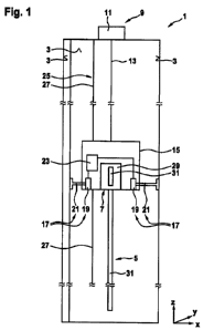
Fig. 1 shows an elevator shaft in which a guide structure is formed by means
of a method
according to an embodiment of the present invention.
Fig. 2 is a sectional view through a guide structure formed according to the
invention.
Fig. 3 is a sectional view through an alternative guide structure formed
according to the
invention.
The drawings are merely schematic and not to scale. Like reference signs
denote like or
equivalent features in the various drawings.
Fig. 1 shows an elevator shaft 1. The elevator shaft 1 is formed by a
substantially cuboid
volume which is formed in a building and is laterally delimited by shaft walls
3. In this
case, the shaft walls 3 extend vertically, i.e. in a z-direction. The elevator
shaft 1 is
delimited at the top and bottom by a ceiling and a floor, respectively, which
extend
horizontally, i.e. in a plane spanned by an x-direction and a y-direction.
An elevator car (not shown) is to be moved vertically in the elevator shaft 1
at a later
point in time. In this case, the elevator car is to be guided on one or more
guide
structures 5 within the elevator shaft 1.
In order to form such a guide structure 5 in the elevator shaft 1, a tool 7
can be received in
the elevator shaft 1 according to embodiments of the method described herein.
In this
case, precautions are taken in order to be able to move the tool 7 vertically
within the
elevator shaft 1 and at the same time position said tool precisely with regard
to the
horizontal position thereof within the elevator shaft 1. The tool 7 is in this
case
configured to form the desired guide structure 5 in the form of a vertically
extending
groove on one of the shaft walls 3 by removing material there during said
vertical
movement within or along the elevator shaft.
CA 03175011 2022-09-09
=
- 13 -
In order to implement these functionalities, as illustrated in a simplified
manner in the
embodiment shown in Fig. 1, a movement device 9 can be provided, for example,
which
is configured to raise or lower the tool 7 vertically along the elevator shaft
1 in a
controlled manner. Such a movement device can be, for example, a cable winch
11 which
can wind and unwind a cable 13 in order to move a frame 15 or car attached to
one end of
the cable 13 within the elevator shaft 1. The tool 7 can be held on or in the
frame 15 or
car.
A lateral position of the tool 7 or of the frame 15 holding said tool can be
influenced by
means of a positioning device 17. For this purpose, the positioning device 17
can have,
for example, an actuator system having actuators 19, by means of which rams 21
can be
moved in the horizontal direction. A plurality of actuators 19 and rams 21 can
be
provided, which can be moved in different directions in order to be able to
move the
lateral position of the tool 7 or the frame 15 overall in the x-direction
and/or the y-
direction. The actuators 19 and rams 21 can possibly also be configured and
operated
such that they can be used to support the tool 7 or the frame 15 on opposite
lateral walls 3
and thus to brace and fix said tool or frame within the elevator shaft 1.
A detection device 23 is also provided. The current lateral position of the
tool 7 or of the
frame 15 within the elevator shaft 1 can be detected by means of the detection
device 23.
For this purpose, the detection device 23 can detect, for example, a vertical
reference
line 25 provided in the elevator shaft 1, the position and/or orientation or
course of which
within the elevator shaft 1 are known. The reference line 25 can be formed by
a plumb
line 27 installed in the elevator shaft 1, for example. Detection signals from
the detection
device 23, which indicate where the tool 7 is currently located relative to
the reference
line 25, can be transmitted to the positioning device 17, so that the
positioning device can
then laterally move the frame 15 with the tool 7 attached thereto into a
desired target
position.
Both the movement of the tool 7 using the movement device 9 and the lateral
positioning
of the tool 7 using the positioning device 17 can be carried out in a fully
automated or at
least partially automated manner. For this purpose, for example, partial
controllers of the
movement device 9, the positioning device 17 and possibly the tool 7 itself
can
communicate with one another or be coordinated by a central controller.
CA 03175011 2022-09-09
- 14 -
In order to be able to remove material on a shaft wall 3 in a targeted manner
using the
tool 7, the tool can be configured as a milling tool, for example. For
example, the tool 7
can have a milling head 29 on which a milling disc 31 is provided. The milling
disc 31
can be circular, for example, and can be driven in rotation. In this case, the
tool 7
corresponds to or resembles a slot cutter or wall chaser.
By moving the tool 7 with its rotating milling disc 31 vertically through the
elevator
shaft 1 while keeping the lateral position thereof precisely at a lateral
target position, i.e.
moving the tool along a desired vertical line through the elevator shaft, for
example, the
milling disc 31 can cut the material from the shaft wall 3 or from a structure
provided on
the shaft wall 3. In this way, a preferably linearly extending groove 33 can
be produced
on the shaft wall 3.
A mechatronic installation component can also be arranged on the frame, for
example in
the form of an industrial robot, which can pick up and guide the tool. In this
case, the
frame can be positioned and fixed at different heights in the elevator shaft,
the tool, in the
fixed state, being moved along a shaft wall in such a way that the guide
structure is
formed by removing material on the shaft wall.
Fig. 2 is a horizontally sectional view through the tool 7 and the groove 33
produced in
the shaft wall 3 by means of said tool. The milling disc 31 removes material
directly from
the shaft wall 3. The shaft wall 3 is typically made of concrete in which
reinforcements 35 are embedded. The reinforcements 35 are typically covered by
a
concrete cover layer 37 a few centimeters thick. When forming the groove 33,
the tool 7
can preferably be positioned such that the groove 33 extends sufficiently
deeply into the
shaft wall 3, but the reinforcements 35 located under the concrete cover layer
37 are not
damaged.
An alternative embodiment for forming the groove 33 on the shaft wall 3 is
shown in
Fig. 3. In this embodiment, the tool 7 does not mill material directly out of
the shaft
wall 3. Instead, a convex structure 39 projecting into an interior of the
elevator shaft 1 is
provided on the shaft wall 3. The convex structure 39 can have an
approximately
rectangular cross section, for example. The convex structure 39 can protrude a
few
CA 03175011 2022-09-09
- 15 -
centimeters beyond a planar surface 41 of the shaft wall 3, for example.
Material can then
be removed from this convex structure 39 by means of the tool 7. In this way,
for
example, a vertically extending groove 33 can be produced in the convex
structure 39. In
this case, the groove 33 can extend more precisely, i.e. for example
straighter and/or more
accurately in accordance with the vertical, than is the case for the convex
structure 39.
As shown in Fig. 3, the convex structure 39 can be formed directly during the
formation
of the shaft wall 3 together with said shaft wall. For example, when the shaft
wall 3 is
cast with concrete, the convex structure 39 can also be cast. In this case,
the convex
structure 39 can be integrated with the shaft wall 3.
Alternatively, as shown in Fig. 4, the convex structure 39 can have been added
to the
shaft wall 3 only after it has been completed. For this purpose, the convex
structure 39
can be formed, for example, by means of a plurality of component segments 42
which are
rectangular in cross section. The component segments 42 can be fixed to the
shaft wall 3.
For example, the component segments 42 can be screwed to the shaft wall 3
using a large
number of relatively small screws 46. Alternatively or additionally, the
component
segments 42 can be glued to the shaft wall 3. A plurality of such component
segments 42
can be fixed to the shaft wall 3 vertically above one another, for example
along
substantially the entire length of the elevator shaft 1, in order to overall
form the convex
structure 39 extending vertically along the shaft wall 3.
The groove 33 formed in the shaft wall 3 or in the convex structure 39 can
later be used
as a guide structure 5 for guiding the elevator car. In this case, for
example, a roller of a
guide shoe provided on the elevator car can roll in the groove 33 and be
guided by the
mutually opposing lateral flanks 43 of the groove 33.
In order to smooth, harden and/or protect a running surface 45 of a guide
structure 5
formed in this way from abrasion, for example, the running surface 45 can be
protected
by means of a plastics layer 47 (see Fig. 2). The running surface 45 can be
formed, for
example, by a base and/or the flanks 43 of the groove 33. The plastics layer
47 can also
have damping properties. For example, the plastics layer can be a few 100 p.m
up to a few
millimeters thick. The plastics layer can be applied, for example, directly
after the
groove 33 has been milled. A suitable application device can be provided on
the tool 7 for
CA 03175011 2022-09-09
, =
v - 16 -
this purpose. Alternatively, the plastics layer can be applied using a
separate device
and/or at a different point in time.
Finally, it should be noted that terms such as "comprising," "having," etc. do
not preclude
other elements or steps, and terms such as "a" or "an" do not preclude a
plurality.
Furthermore, it should be noted that features or steps that have been
described with
reference to one of the above embodiments may also be used in combination with
other
features or steps of other embodiments described above. Reference signs in the
claims
should not be considered limiting.