Note: Descriptions are shown in the official language in which they were submitted.
CA 03175164 2022-09-13
DRIVE ARRANGEMENT FOR THE DISPLACEMENT OF A CONTACTING DEVICE
AS WELL AS CONTACTING DEVICE AND USE THEREOF
The invention relates to a drive arrangement for the displacement of a
contacting
device according to the features of patent claim 1 as well as to such a
contacting
device and use thereof.
In the prior art, current collectors, so-called pantographs, are known. It
involves a
kinematic system for displacing a contacting device from a lowered position to
a
raised position against a contact wire. However, there are also applications
in which
a contacting device is to be displaced from a raised to a lowered position
against a
counterpart.
The invention is based on the object to provide a drive device for such a
contacting
device with a subjacent counterpart, which drive device is suitable to
interrupt the
contact to the counterpart in the event of a malfunction and at the same time
is
designed to apply a defined contact pressure without the need for a complex
control
or regulation system. A corresponding contacting device and its use shall be
provided.
The object is attained with a drive arrangement having the features of patent
claim 1.
A suitable contacting device is subject matter of patent claim 11. The use of
such a
contacting device for establishing an electrically conductive contact with a
counterpart below the contacting device is subject matter of patent claim 12.
The
subclaims set forth advantageous refinements.
The drive arrangement according to the invention is provided to displace a
contacting
device from a raised position to a lowered position. The contacting device is
designed
for this purpose to come into electrically conductive contact with a
counterpart at
different heights. This counterpart can, for example, be a contacting device
on a roof
1
Date Recue/Date Received 2022-09-13
CA 03175164 2022-09-13
area of a motor vehicle that is to be charged in a charging station by means
of the
contacting device. Also involved may be, e.g., a watercraft that is to be
electrically
charged. Ships that are loaded and unloaded in port and are exposed to the
tidal
range have an almost constantly changing vertical position.
The drive arrangement includes a first arm as upper arm and a second arm as
guide
arm, which together with a third arm as lower arm form a four-joint linkage.
The lower
arm includes a free lower end which carries the contacting device. By
displacing the
third arm by means of the first arm and the second arm within the four-joint
linkage,
the contacting device can be displaced to the desired raised or lowered
position.
An actuator is in active engagement with the first arm via an actuating lever.
The first
arm is quasi the drive arm. The second arm is a guide arm to guide the third
arm.
The actuating lever between the actuator and the first arm is connected for
pivotal
movement with the first arm. It is under the influence of a spring force to
support the
actuating lever in a position upon the first arm, so that the first arm is
also under the
influence of the spring force. The spring force can be a tensile force or a
compressive
force. This means that the actuating lever is either pushed against the first
arm or
pulled against the first arm under the influence of the spring force. The
spring force
counteracts the actuating force. The spring force can act on the actuating
lever at the
same point as the actuating force. In terms of the operating principle of the
drive
arrangement, the positions of the points, upon which the spring force and the
actuating force act on the actuating lever, are irrelevant. For a compact
design, the
spring force and the actuating force may coincide at one point. If a spring is
to be
dimensioned smaller, this can be compensated by a greater lever arm. If, on
the
other hand, the actuating force is to be reduced, the actuator can be combined
with a
greater lever arm, i.e. the actuating force can act at a greater distance from
a pivot
point of the lever arm. It is generally simpler in terms of design, when the
points of
attack for the actuating force and the spring force are not identical, so that
the spring
2
Date Recue/Date Received 2022-09-13
CA 03175164 2022-09-13
force and the actuating force are in active engagement with the actuating
lever at a
distance from each other. Within the scope of the invention, the term active
engagement does not mean that the spring itself must be connected to the
actuating
lever. The spring force can also be transmitted from the spring to the
actuating lever
via intermediate elements such as coupling rods, connecting elements or other
suitable transmission elements. The same applies to the connection between the
actuator and the actuating lever.
The counteraction of spring force and actuating force is to be understood in
the
sense of oppositely directed force vectors. The vector of the spring force
does not
necessarily have to coincide with the orientation of e.g. a helical
compression spring.
It is sufficient when the spring force predominantly counteracts the actuating
force.
The weight force which pushes the contacting device downwards against the
counterpart is intended to ensure contact with the counterpart over a very
wide
vertical adjustment range, without the spring force having any influence on
the
contacting force. It is not the spring force that pushes the contacting device
against
the counterpart, nor is it the actuating force. Rather, the actuator is
intended to
displace the actuating lever during lowering to such an extent that the
contacting
device quasi rests on the counterpart in a floating manner. The counterpart
can
change its vertical position within a very large stroke range without changing
the
contact force thereby. The invention therefore enables to realize an
essentially
constant contact pressure without complex electromechanical controls or
regulations.
A certain influence of the spring force becomes effective only when the spring
force
acts on the actuating lever at a different point than the actuating force.
Depending on
the positioning or lever ratios, the spring force can partly increase and also
partly
reduce the contact pressure.
3
Date Recue/Date Received 2022-09-13
CA 03175164 2022-09-13
The spring force or a spring is primarily provided for emergency operation. An
emergency occurs when the actuating lever can no longer apply any actuating
force,
for example because it is de-energized. In this case, provision may be made,
for
example, for a spindle drive to be decoupled and for the spring force to
retract the
spindle. Theoretically, it is also conceivable that in the event of a power
failure, an
emergency power source is utilized, for example by a battery to drive a
spindle drive
of the actuating lever in order to raise the first arm with the assistance of
the spring
force.
Solely by the influence of the spring force can it become possible to hold the
contacting device in a raised position in which the contacting device is
without
contact to the counterpart. In order to displace the contacting device into a
lowered
position or to pivot the first arm, the actuator has the actuating force which
exerts
upon the actuating lever an actuating torque which is greater than a restoring
torque
caused by the spring force on the actuating lever. As a result, the actuating
lever can
be displaced from the engagement position to a release position.
The actuating lever is supportable on the first arm via a catch when the first
arm is
displaced to the raised position, and is detachable from the arm when the
first arm is
displaced to a lowered position.
In the release position, the moment generated by the weight of the contacting
device
dominates. Since the actuating lever is pivotally connected to the first arm,
the first
arm in the lowered position is largely free from the influence of the spring
force and
also free from the influence of the actuating force. The contacting device is
pulled
downwards by its own weight and rests on the counterpart by its own weight.
The
contact force with which the contacting device contacts the counterpart
depends to a
large extent on the weight force of the contacting device and the four-joint
linkage
arranged on it, and does not depend on the spring force.
4
Date Recue/Date Received 2022-09-13
CA 03175164 2022-09-13
The travel speed of the entire system, with its movement being determined by
the
contact of the catch with the first arm, is controlled by the speed of the
actuator.
A further advantage of the drive arrangement according to the invention is to
be seen
in conjunction with motor vehicles, because they can raise or lower themselves
in the
loading position, for example by changing the load. In this operating state,
the
contact force of the contacting device should not increase so as not to damage
the
motor vehicle. At the same time, however, it may also not be reduced in order
to
ensure a safe energy flow and to avoid electric arcs. The contact force of the
contacting device should be kept as constant as possible. This is achieved by
the
release position of the catch, which leads to a floating, i.e. not force-
guided support in
the upward direction of the contacting device upon the counterpart. The weight
force
with which the contacting device rests upon a counterpart is generated in
particular
only by the weight of the contacting device.
The catch is provided to support upon a mounting on the first arm. An
adjustable
spacer can be arranged on the catch or on the mounting in order to adjust the
distance between the catch and the mounting. The position of the four-joint
linkage
can be determined in the raised position can be determined via the spacer, for
example a threaded bolt.
The first arm includes a first, upper end. In the area of this end, the
actuating lever is
connected to the first arm in an articulated manner. The area of this first
end includes
in particular the area of the bearing of the first arm, which bearing is at
the same time
also the main bearing via which the drive arrangement and also the contacting
device
are held.
The second arm serves primarily as a guide arm so that the third arm or the
contacting device arranged thereon executes the desired movement. The
articulated
connection between actuating lever and first arm is located in immediate
proximity to
Date Recue/Date Received 2022-09-13
CA 03175164 2022-09-13
this main bearing or to the main bearing axis of the first arm. It can also be
located
directly on the main bearing axis.
In the area of the first end, a bearing support for the actuating lever is
preferably
arranged on the first arm. The actuating lever is mounted in an articulated
manner on
this bearing support. The bearing support is in particular arranged on a
bearing
sleeve for the main bearing on the first arm. As a result, the bearing support
is
pivoted together with the bearing sleeve of the first arm. This bearing
support can be
used at the same time to support the mounting. The bearing support then has a
dual
function: On one hand, it serves as support for the actuating lever and, on
the other
hand, the forces exerted by the spring or the actuator can be transmitted via
the
mounting. The torque applied to raise the first arm via the actuating lever is
largely
determined by the distance of the bearing of the actuating lever from the main
bearing and by the position of the mounting.
The actuator is preferably designed as a linear drive. This may involve an
electrically
driven spindle drive or also a piston and cylinder arrangement that is driven
hydraulically or pneumatically.
Preferably, the actuator in the form of a linear drive acts essentially
parallel to the
spring force. The spring force is in particular a tensile force, since in this
case the
spring can be arranged in a very space-saving manner between the main bearing
and the bearing point of the second arm in the uppermost region of the drive
arrangement. Since the spring exerts a tensile force, a counteracting actuator
must
exert a compressive force, at least when both components are arranged
essentially
parallel next to each other.
To ensure that the actuator does not have to apply a greater moment than is
generated by the spring force, the spring force preferably engages between an
articulated connection of the actuating lever with the actuator and an
articulated
6
Date Recue/Date Received 2022-09-13
CA 03175164 2022-09-13
connection between the actuator and the bearing support. As a result, the
lever arm
of the actuator in relation to the main bearing of the first arm is greater
than the lever
arm of the spring in relation to the main bearing of the first arm. Depending
on the
position of the articulated connections and depending on the length and design
of the
actuating lever, the actuating force can be reduced in this manner. It is
therefore
quite possible that, due to the lever ratios, the actuating force to be
applied by the
actuator is significantly lower than the spring force acting in the opposite
actuating
direction. Decisive is that the force acting upwards on the contacting device
due to
the restoring torque in the release position is smaller than the weight force
acting
downwards on the contacting device.
The spring or spring force can also be arranged at a greater distance than the
actuator from the articulated connection between the actuating lever and the
first
arm. In other words, the spring may be arranged below and the actuator above
the
spring. Arrangements of actuators and springs arranged side by side, as viewed
in
the horizontal direction, are also possible. The spring force may also be
applied by
multiple springs. The invention is not limited to a single spring.
In addition to a pure drive arrangement for different contacting devices, the
invention
also relates in particular to a contacting device with such a drive
arrangement as has
been explained above. The contacting device involves in particular a device
for
establishing an electrically conductive contact, e.g. at a stationary charging
station,
with a mobile counterpart, e.g. a motor vehicle.
In the practical use of a contacting device for establishing a conductive
contact
between the contacting device and a counterpart located below the contacting
device, the actuating lever is displaced to a release position so that the
counterpart is
in contact with the contacting device predominantly or exclusively under the
influence
of the weight force of the contacting device and the arms connected thereto.
The
contacting device remains in this position until, e.g., a charging process is
completed.
7
Date Recue/Date Received 2022-09-13
CA 03175164 2022-09-13
The actuator then acts in the opposite direction so that the actuating lever
comes
again to rest upon the mounting. The actuating lever with the mounting now
serves
as a catch to swing back the first arm.
Resetting can be realized exclusively by the spring force, for example in an
emergency situation. For this purpose, the contacting device is raised without
actuation of the actuator to such an extent that the contacting device is only
raised
further by the spring force. In normal operation, resetting is realized in a
controlled
manner under the influence of the actuator.
The invention will be explained in more detail hereinafter by way of exemplary
embodiments illustrated in the purely schematic drawings.
It is shown in:
Figure 1 a simplified illustration of a drive arrangement in a lowered
position;
Figure 2 a detail of the drive arrangement of Figure 1;
Figure 3 the drive arrangement of Figure 1 in a lowered position, with the
actuating lever in a release position;
Figure 4 a detail of Figure 3;
Figure 5 the drive arrangement of Figures 1 to 4 in a higher position;
Figure 6: a detail of Figure 5;
Figure 7: the drive arrangement of Figures 1 to 6 in the raised position;
8
Date Recue/Date Received 2022-09-13
CA 03175164 2022-09-13
Figure 8: a detail of Figure 7.
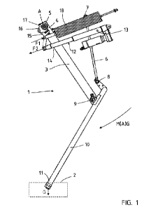
Figure 1 shows a side view of a drive arrangement 1 for a contacting device 2,
which
is displaceable from a raised position to a lowered position as shown. The
drive
arrangement 1 is suspended and attached to a supporting frame, which is not
shown
in greater detail and is located above the drive arrangement 1. It has several
arms
which form a four-joint linkage. A first arm 3 is the main arm and has a main
bearing
at its first, upper end 4. The main bearing 5 is connected to the frame in a
manner
not shown in greater detail. A second arm 6 has at its first, upper end a
bearing 7, via
which the second arm 6 is connected to the frame, and at the second, lower end
a
lower bearing 8. The first arm 3 also has such a lower bearing 9. Both lower
bearings 8, 9 are arranged at a distance from one another and connected to one
another in a pivotable manner via a third arm 10. The distance between the
lower
bearings 8, 9 is relatively small in relation to the overall length of the
third arm 10. As
a result, a lower end 11 of the third arm 10, which lower end is connected to
the
contacting device 2, can be pivoted over a relatively large stroke range.
The upper bearing 7 of the second arm 6 and the main bearing 5 are stationary
joints. The entire drive arrangement including the contacting device 2 is
supported via
these two bearings 5, 7, with the main load being borne by the first arm 3,
while the
second arm 6 is provided for kinematic reasons to guide the third arm 10 or
the
contacting device 2.
The drive arrangement 1 according to the invention includes an actuator 12. It
involves a linear drive. It includes an actuating cylinder 13 in which a
piston rod 14 is
guided. The piston rod 14 is pivotally connected with a bearing on the
actuating
lever 15, with the actuating lever 15 being pivotally connected to the first
arm 3 via a
bearing support 16 by means of a further bearing. The bearing support 16 is
connected in fixed rotative engagement with a bearing sleeve 17 of the bearing
support 16, in particular welded. The bearing sleeve 17 is part of the first
arm 3 and
9
Date Recue/Date Received 2022-09-13
CA 03175164 2022-09-13
rotates about the main bearing 5 as the first arm 3 pivots. Accordingly, the
angular
position of the bearing support 16 with respect to the first arm 3 is the same
at all
times.
The actuating lever 15 is further connected to a spring 18, which exerts a
spring
force Fl upon the actuating lever 15. The spring 18 and the actuator 12 are
supported on the frame.
The actuator 12 exerts a force F2 upon the actuating lever 15. Figure 2 shows
an
enlarged view of the area of the main bearing 5 of the drive arrangement 1.
The main
bearing 5 with the bearing sleeve 17 defines the pivot axis A for the bearing
support 16, which is fixedly connected to the first arm 3. On the bearing
support 16,
the actuating lever 15 is pivotally connected with the bearing support 16 in
the area
of a pivot axis B. The further pivot axes C, D relate to the spring 18 and the
drive
unit 12. In an embodiment not shown in greater detail, the pivot axis B of the
bearing
support 16 coincides with the pivot axis A of the main bearing 5. The position
of the
pivot axis B in proximity to the main bearing 5 plays a minor role.
The actuating lever 15 is in contact with the bearing support 16 via two
regions. The
first contact involves the articulated connection in the pivot axis B. The
second
contact is between a catch 19 on the actuating lever 15 and a mounting 22 on
the
bearing support 16. As a result of this contact, the pivotal movement
capability of the
bearing support 16 is restricted in one direction, namely in the direction in
which the
spring force F1 acts.
In this exemplary embodiment, the mounting 22 is oriented parallel to a
straight
line G(AB) through the pivot axes A and B. Parallelism is not necessarily
required,
however the position of the mounting 22 is such that the catch 19 can rest on
it when
the actuating lever 15 is pivoted.
Date Recue/Date Received 2022-09-13
CA 03175164 2022-09-13
A torque M(A)G acts on the arm 3 in the pivot axis A of the main bearing 5 due
to the
weight force G of the contacting device 2. This torque M(A)G is so great that
the
mounting 22 is pushed against catch 19.
A spacer 20 in the form of a screw bolt is arranged on the catch 19 to adjust
the
distance between the catch 19 and the mounting 22. When the distance is
increased,
the arm 3 can no longer pivot downwards to the extent as shown in Figure 2.
The
spacer 20 can be used to determine the lower and upper end positions or the
maximum lowered and raised positions.
When the piston rod 14 is retracted, the catch 19 forces the bearing support
16 into a
counterclockwise rotational movement via the pressure on the mounting 22 and
via
the pull in the area of the pivot bearing B. The connection between the
bearing
support 16 and the bearing sleeve 17 causes the arm 3 to pivot
counterclockwise
and as a result the contacting device 2 is raised.
Figure 3 shows the state of the drive arrangement 1 in the lowered position,
but with
the difference to Figure 1, that the contacting device 2 rests against a
counterpart 21.
The contacting device 2 is therefore in a slightly raised position compared to
Figure 1. The third arm 10 is not pivoted quite as far as in the exemplary
embodiment
in Figure 1. As a result, there are also different angular positions for the
first arm 3
and the second arm 6. This in turn has an influence on the position of the
actuating
lever 15, as explained with reference to the enlarged illustration of Figure
4.
Compared to Figure 2, the piston rod 14 has not been extended any further.
However, since the counterclockwise movement of arm 3 has also caused the
bearing support 16 to pivot counterclockwise, the mounting 22 is no longer in
contact
with the catch 19. As a result, the straight line G(AB) between the two pivot
bearings A and B is at a greater angle W1 in relation to the direction of the
spring
force F1 than in Figure 1. However, the spring force F1 is not so great that
the torque
11
Date Recue/Date Received 2022-09-13
CA 03175164 2022-09-13
of the weight force M(A)G could be overcome to thereby lift the arm 3. This is
due,
i.a., to the very small distance between the pivot axes A and B and to the
acute
angle W1, which is less than 45 . The release position of the actuating lever
15, as
illustrated in Figures 3 and 4, enables upon the counterpart 21 a contact
force which
is determined predominantly by the weight force.
Figures 5 and 6 show a situation in which the first arm 3 has been raised even
further. The actuator 12 has not been extended or retracted any further, but
has the
same position as in Figure 4. This illustration makes it clear that even when
the
contacting device 2 has been displaced almost completely upwards, it is still
possible
to generate a sufficient weight force G to ensure an electrical connection
with a
counterpart.
At the same time, these Figures can be used to explain the situation that can
arise in
the event of a failure of the supply energy for the actuator 12. In this case,
the piston
rod 14, as shown in the enlarged illustration of Figure 6, is blocked. After
the
blockage has been released, the spring force F1 pulls the piston rod 14 back
so that
the angle W1 indicated in Figure 6 is reduced to such an extent that the catch
19 on
the actuating lever 15 is pivoted upwards in the drawing plane and comes to
rest
again upon the mounting 22 in order to maintain the arm 3 in the raised
position.
Figures 7 and 8 finally show the fully raised position, in which the catch 19
again acts
against the mounting 22. It is apparent that the piston rod 14 is now
retracted. In the
raised position, the entire drive arrangement 1 is extremely compact and
provides a
high clearance height below the drive arrangement 1.
12
Date Recue/Date Received 2022-09-13
CA 03175164 2022-09-13
Reference Signs
1 - drive arrangement
2 - contacting device
3- first arm
4 - first end of 3
- main bearing
6 - second arm
7- upper bearing of 6
8- lower bearing of 6
9 - lower bearing of 3
10- third arm
11- lower end of 10
12- actuator
13 - actuating cylinder of 12
14- piston rod of 12
- actuating lever
16 - bearing support
17 - bearing sleeve of 5
18- spring
19- catch on 15
20- spacer on 19
21 - counterpart
22- mounting
F1 - spring force
F2 - actuating force
G- weight force
G(AB) - straight line through A and B
Ml- torque by F1
13
Date Recue/Date Received 2022-09-13
CA 03175164 2022-09-13
M(A)G -torque by G
A- pivot axis of 5
B - pivot axis between 15 and 16
C - pivot axis between 15 and 18
D - pivot axis between 12 and 15
W1 - angle between G (weight force) and F1
14
Date Recue/Date Received 2022-09-13