Note: Descriptions are shown in the official language in which they were submitted.
WO 2021/242603
PCT/US2021/033417
OSTOMY LEAKAGE DETECTION SYSTEM
BACKGROUND
[0001] The following description relates generally to
a leakage
detection system for medical devices, and more particularly to leakage
detection
system for ostomy appliances.
[0002] An ostomy pouch system typically includes a
pouch formed
from opposing walls defining an internal collection area, an inlet opening for
receiving a stoma, and an ostomy appliance for attaching the pouch to a user.
The
ostomy appliance may include, for example, an ostomy barrier of a one-piece
pouch
system, which is attached to a body-side pouch wall proximate an inlet
opening, a
baseplate for a two-piece pouch system configured to releasably engage a
pouch, and
a barrier ring. The ostomy appliance may include a skin barrier material for
adhering
to and sealing against user's peristomal skin surrounding the stoma.
[0003] The ostomy appliance may be susceptible to
ostomy effluent
leakage, and the seal formed between the skin barrier material and the user
may
weaken. Often times, the user may be unaware of or cannot easily assess an
extent of
weakening in the seal. Thus, the user may not become aware of a weakened seal,
and
consequently, the ostomy effluent may leak through to an exterior of the
ostomy
appliance.
[0004] Accordingly, it is desirable to provide a
leakage detection
system for ostomy appliances.
BRIEF SUMMARY
[0005] In one aspect, a sensing accessory for
detecting leakage in a
medical device is provided. The sensing accessory may include a sensor region,
a
connector region, and an elongated tail region extending therebetween. The
sensor
region may comprise a center opening and a plurality of sensors arranged
around the
center opening. The plurality of sensors may include at least two
substantially
elliptical conductive traces substantially surrounding the center opening and
at least
two arc-shaped conductive traces. The at least two substantially elliptical
conductive
traces may include a first trace and a second trace, and the at least two arc-
shaped
conductive traces may include a first arc trace and a second arc trace. Each
of the two
CA 03175645 2022- 10- 14
WO 2021/242603
PCT/US2021/033417
substantially elliptical conductive traces may be arranged at a different
radial distance
from the center opening, and each of the at least two arc-shaped conductive
traces
may be arranged in a different sector in the sensor region. The connector
region may
include a plurality of connection points provided at terminal ends of the
plurality of
sensors for electrical connection to an external device.
[0006] In an embodiment, the first trace may be
arranged at a first
radial distance from the center opening, the second trace may be arranged at a
second
radial distance from the center opening, the first arc trace may be arranged
at a third
radial distance from the center opening, and the second arc trace may be
arranged at a
fourth radial distance from the center opening, wherein the third and fourth
radial
distances are greater than the second radial distance and the second radial
distance is
greater than the first radial distance. In such an embodiment, the first
trace, the
second trace, and the first and second arc traces may be arranged in three
substantially
concentric layers substantially surrounding the center opening. The sensing
accessory
may be configured to measure a resistance of the medical device between the
first
trace and the second trace and between the second trace and each of the at
least two
arc-shaped conductive traces.
[0007] In an embodiment, the first trace may be a
first level trace and
the second trace may be a first ground trace, and the at least two
substantially
elliptical conductive traces may further include a second level trace, a
fourth level
trace, a fifth level trace, a second ground trace, and a third ground trace,
and the at
least two arc-shaped conductive traces may further include a third arc trace
and a
fourth arc trace. The first level trace may be arranged at a first radial
distance from
the center opening, the first ground trace may be arranged at a second radial
distance
from the center opening, a second level trace may be arranged at a third
radial
distance from the center opening, the second ground trace may be arranged at a
fifth
radial distance from the center opening, the fourth level trace may be
arranged at a
sixth radial distance from the center opening, the fifth level trace may be
arranged at a
seventh radial distance from the center opening, the third ground trace may be
arranged at an eighth radial distance from the center opening, and the first,
second,
third, and fourth arc traces may be arranged at a fourth radial distance from
the center
opening, wherein a radial distance may increase from the first radial distance
to the
eighth radial distance, wherein first radial distance < second radial distance
< third
radial distance < fourth radial distance < fifth radial distance < sixth
radial distance <
2
CA 03175645 2022- 10- 14
WO 2021/242603
PCT/US2021/033417
seventh radial distance < eighth radial distance. In such an embodiment, the
level
traces, the ground traces, and the arc traces may be arranged in eight
substantially
concentric layers substantially surrounding the center opening. The sensing
accessory
may be configured to measure a resistance of the medical device between the
first
level trace and the first ground trace, between the first ground trace and the
second
level trace, between each of the first, second, third, and fourth arc traces
and the
second ground trace, between the second ground trace and the fourth level
trace, and
between the fifth level trace and the third ground trace.
[0008] Each of the first, second, third, and fourth
arc traces may be
arranged in a different quadrant in the sensor region. For example, the first,
second,
third, and fourth arc traces may be arranged in intercardinal directions of
the sensor
region with the tail region being arranged at south. In such an embodiment,
the first
arc trace may extend along a southeast (SE) quadrant of the sensor region. The
second arc trace may be formed from an exposed portion of a curved conductive
trace
extending along an east half of the sensor region, wherein a lower portion of
the
curved conductive trace may be covered with a masking layer to provide the
second
arc trace extending along a northeast (NE) quadrant of the sensor region. The
third
arc trace may be formed from an exposed portion of a curved conductive trace
extending along an west half of the sensor region, wherein a lower portion of
the
curved conductive trace may be covered with a masking layer to provide the
third arc
trace extending along a northwest (NW) quadrant of the sensor region_ The
fourth arc
trace may extend along a southwest (SW) quadrant of the sensor region.
[0009] In such an embodiment, the sensing accessory
may be
configured to measure a resistance of the medical device between the first
level trace
and the first ground trace for determination of a level 1 leakage, a
resistance between
the first ground trace and the second level trace for determination of a level
2 leakage,
a resistance between the first arc trace and the second ground trace for
determination
of a level 3 leakage in the SE quadrant, a resistance between the second arc
trace and
the second ground trace for determination of a level 3 leakage in the NE
quadrant, a
resistance between the third arc trace and the second ground trace for
determination of
a level 3 leakage in the NW quadrant, a resistance between the fourth arc
trace and the
second ground trace for determination of a level 3 leakage in the SW quadrant,
a
resistance between the second ground trace and fourth level trace for
determination of
a level 4 leakage, and a resistance between the fifth level trace and the
third ground
3
CA 03175645 2022- 10- 14
WO 2021/242603
PCT/US2021/033417
trace for determination of a level 5 leakage. The severity of a leakage may
increase
from level 1 leakage to level 5 leakage, wherein level 1 leakage < level 2
leakage <
level 3 leakage < level 4 leakage < level 5 leakage, wherein the level 5
leakage may
be a critical leakage.
100101 In another embodiment, the at least two
substantially elliptical
conductive traces may include first, second, third, and fourth traces, and the
at least
two arc-shaped conductive traces may include first, second, third and fourth
arc
traces. The first trace may be arranged at a first radial distance from the
center
opening, the second trace may be arranged at a second radial distance from the
center
opening, a third trace may be arranged at a fourth radial distance from the
center
opening, the fourth trace may be arranged at a fifth radial distance from the
center
opening, and the first, second, third, and fourth arc traces are arranged at a
third radial
distance from the center opening, wherein a radial distance may increase from
the first
radial distance to the fifth radial distance, wherein first radial distance <
second radial
distance < third radial distance < fourth radial distance < fifth radial
distance. In such
an embodiment, the first, second, third, and fourth traces, and the first,
second, third,
and fourth arc traces may be arranged in five substantially concentric layers
substantially surrounding the center opening, wherein the first arc trace
extends along
a SE quadrant, the second arc trace extends along a NE quadrant, the third arc
trace
extends along a NW quadrant, and the fourth arc trace extends along a SW
quadrant
of the sensor region.
[0011] In such an embodiment, the sensing accessory
may be
configured to measure a resistance of the medical device between the first
trace and
the second trace for determination of a level 1 leakage, a resistance between
the
second trace and the first arc trace for determination of a level 2 leakage in
the SE
quadrant, a resistance between the second trace and the second arc trace for
determination of a level 2 leakage in the NE quadrant, a resistance between
the
second trace and the third arc trace for determination of a level 2 leakage in
the NW
quadrant, a resistance between the second trace and the fourth arc trace for
determination of a level 2 leakage in the SW quadrant, a resistance between
the first
arc trace and the third trace for determination of a level 3 leakage in the SE
quadrant,
a resistance between the second arc trace and the third trace for
determination of a
level 3 leakage in the NE quadrant, a resistance between the third arc trace
and the
third trace for determination of a level 3 leakage in the NW quadrant, a
resistance
4
CA 03175645 2022- 10- 14
WO 2021/242603
PCT/US2021/033417
between the fourth arc trace and the third trace for determination of a level
3 leakage
in the SW quadrant, and a resistance between the third trace and fourth trace
to
determine a level 4 leakage. The severity of a leakage may increase from level
1 to
level 4, wherein level 1 leakage < level 2 leakage < level 3 leakage < level 4
leakage,
wherein the level 4 leakage may be a critical leakage.
[0012] In any of the foregoing embodiments, the
medical device may
be an ostomy appliance including an adhesive layer configured for attachment
to a
peristomal skin of a user, wherein the plurality of sensors may be arranged
adjacent
the adhesive layer to measure a resistance of the adhesive layer.
[0013] In an embodiment, the sensor region may have a
ring-like
shape, and the center opening may be configured to receive a stoma. Each of
the at
least two substantially elliptical conductive traces and the at least two arc-
shaped
conductive traces may extend from the sensor region through the tail region to
the
connector region and terminate at the plurality of connection points.
[0014] The sensing accessory may include a sensor
layer having a
body-side and a distal side, an adhesive layer arranged on the body-side of
the sensor
layer, and a backing layer arranged on the distal side of the sensor layer.
The sensor
layer may include a substrate, wherein the plurality of sensors may be
provided on a
body-side of the substrate and in contact with the adhesive layer. The sensing
accessory may be configured to measure a resistance of the adhesive layer
using the
plurality of sensors.
[0015] In an embodiment, the backing layer may be
formed from an
adhesive. In such an embodiment, the sensing accessory may include a body-side
release liner covering the adhesive layer and a distal side release liner
covering the
backing layer. Each of the release liners may include a tab configured to
facilitate
removal of the release liners, wherein the tabs may be arranged offset from
each
other. In some embodiments, the release liners may include indicator labels to
guide
assembling of the sensing accessory with an ostomy appliance and attachment of
the
assembled sensing accessory and ostomy appliance to a user.
[0016] In an embodiment, exposed portions of the tail
region of the
sensor layer may be covered with a tail cover. The tail cover may also cover a
portion
of the connector region and include a wing-like extensions in the connector
region,
wherein an adhesive is provided on the wing-like extensions for attachment to
an
ostomy pouch or a user.
CA 03175645 2022- 10- 14
WO 2021/242603
PCT/US2021/033417
[0017] In an embodiment, the sensing accessory may be
configured to
attach to an ostomy barrier. In such an embodiment, the backing layer may be
attached to the ostomy barrier, and the adhesive layer may be attached to a
peristomal
skin of a user. The adhesive layer may be formed from a hydrocolloid adhesive
configured to exhibit a resistance drop from greater than 2 ME/ to about 1 la2
when
exposed to an ostomy effluent.
[0018] In an embodiment, the sensing accessory may be
configured to
stretch to conform to a convex ostomy barrier, wherein the substrate and the
plurality
of sensors may be formed from stretchable materials.
[0019] In another aspect, a leakage detection system
for an ostomy
appliance is provided. The leakage detection system may include the sensing
accessory according to any of the foregoing embodiments and a wearable
subsystem
configured to communicate with the sensing accessory and receive signals from
the
sensing accessory to detect an ostomy effluent leakage.
[0020] In an embodiment, the wearable subsystem may
include a
hinged case comprising a bottom housing, a top housing, and a hinge connecting
the
bottom housing and the top housing. The hinged case may be configured to be
closed
after the wearable subsystem is connected to the connector region to secure
the
wearable subsystem to the sensing accessory.
[0021] In some embodiments, the sensing accessory may
include a
first alignment member and the wearable subsystem may include a second
alignment
member, which may be configured to engage with each other to facilitate
correct
alignment and connection between the sensing accessory and the wearable
subsystem.
The first alignment member may include at least one opening in the connector
region
of the sensing accessory, and the second alignment member may include at least
one
raised member, wherein the at least one raised member may be configured to be
received in the at least one opening.
[0022] In an embodiment, the second alignment member
may include
a center raised key member and a peripheral raised member. The center raised
key
member may be provided generally in the center of the bottom housing and the
peripheral raised member may be arranged proximate the hinge. The first
alignment
member may include a center key opening configured to receive the center
raised key
member and a peripheral opening configured to receive the peripheral raised
member.
The wearable subsystem may further include a plurality of conductive members
6
CA 03175645 2022- 10- 14
WO 2021/242603
PCT/US2021/033417
configured to contact the plurality of connection points to electrically
connect the
wearable subsystem to the sensing accessory. The plurality of conductive
members
may be arranged proximate and surrounding the center raised key member.
[0023] In another embodiment, the second alignment
member may
include first and second raised members. The first alignment member may
include a
first opening configured to receive the first raised member and a second
opening
configured to receive the second raised member. In such an embodiment, the
wearable subsystem may also include a plurality of conductive members arranged
between the first and second raised member for electrically connecting the
wearable
subsystem to the sensing accessory.
[0024] In an embodiment, the leakage detection system
may include a
charging dock configured to connect to the wearable subsystem to charge a
rechargeable battery of the wearable subsystem. The charging dock may also be
configured to wirelessly communicate with the wearable subsystem to receive
leakage
signals and send an alert to a user.
[0025] In an embodiment, the plurality of conductive
members may
comprise a plurality of raised conductive pads.
[0026] In any of the foregoing embodiments, the tail
region may be
flexible to allow the wearable subsystem to be attached to a user or to the
ostomy
appliance at various locations when the wearable subsystem is attached to the
sensor
accessory.
[0027] The wearable subsystem may be configured to
analyze signals
received from the sensing accessory, communicate with external devices, and
alert a
user to notify a leakage event and/or a status of the ostomy appliance, for
example,
via sound, vibration, and/or light. In an embodiment, the wearable subsystem
may be
configured to poll resistance measurements from the plurality of sensors to
collect
resistance data and process the resistance data through an algorithm to
determine an
ostomy effluent leakage event, and alert a user according the severity of the
leakage
event. The wearable subsystem may also be configured to detect and communicate
a
connectivity status between the wearable subsystem and the sensing accessory
and a
faulty sensor to a user or to an external device.
[0028] In some embodiments, the wearable subsystem may
include a
rechargeable battery. In such embodiments, the leakage detection system may
further
include a charging dock for charging the rechargeable battery of the wearable
7
CA 03175645 2022- 10- 14
WO 2021/242603
PCT/US2021/033417
subsystem. The charging dock may also be configured to wirelessly communicate
with the wearable subsystem to receive leakage signals and send an alert to a
user.
[0029] In an embodiment, the charging dock may
comprise a housing
configured to receive the wearable subsystem and charging pins. The wearable
subsystem may include conductive pads configured to electrically connect to
the
charging pins. The charging dock may also include a device for generating a
sound
and/or light to alert a user and a wireless communication module for
communicating
with the wearable subsystem and/or a mobile application.
[0030] In an embodiment, the leakage detection system
may also
include a mobile application configured to wirelessly communicate with the
wearable
subsystem and/or the charging dock. The mobile application may be provided as
an
application for a mobile phone. In such an embodiment, the wearable subsystem
may
be configured to transmit data to the mobile application. The transmitted data
may
include raw resistance measurements as received from the sensing accessory
and/or
processed data generated by processing the resistance measurements at the
wearable
subsystem. The processed data may include a leakage event information and/or a
summary of the resistance measurements.
[0031] The mobile application may be configured to
provide means for
a user to interact with the leakage detection system to set user's preferences
for alerts
and to review information about the ostomy appliance. The information may
include
leakage patterns, historical data of user's ostomy appliance usage, and/or
ostomy
appliance usage trends. The mobile application may also be configured to
connect a
user to ostomy training materials, experts at ostomy appliance suppliers,
and/or
ostomy clinicians. Further, the mobile application may be configured to check
a
connectivity between the mobile application and the wearable subsystem and/or
a
connectivity between the mobile application and the charging dock and alert a
user.
[0032] In an embodiment, the mobile application may be
configured to
receive a leakage event information from the wearable subsystem and alert a
user
through alert functions of a mobile phone. Further, the mobile application may
be
configured to transmit data to a cloud server for storage and analysis to
provide a
prediction of a leakage event based on user's historical data, comparison data
against
leakage patterns of other users, product recommendations based on user's
leakage
patterns, and/or a prompt for re-ordering ostomy products. The mobile
application
8
CA 03175645 2022- 10- 14
WO 2021/242603
PCT/US2021/033417
may also be configured to manage a storage of photographs of user's stoma
and/or
peristomal skin for tracking with user's leakage patterns.
[0033] Other aspects, objectives and advantages will
become more
apparent from the following detailed description when taken in conjunction
with the
accompanying drawings.
BRIEF DESCRIPTION OF THE DRAWINGS
[0034] The benefits and advantages of the present
embodiments will
become more readily apparent to those of ordinary skill in the relevant art
after
reviewing the following detailed description and accompanying drawings,
wherein:
[0035] FIG. 1 is a perspective illustration of an
ostomy pouch
appliance and a leakage detection system according to an embodiment;
[0036] FIG. 2 is a schematic illustration of an ostomy
pouch appliance
including leakage detection sensors according to an embodiment;
[0037] FIG. 3 is a graph of resistance measured by a
sensing accessory
according to an embodiment;
[0038] FIG. 4 is a schematic illustration of leakage
sensors comprising
a plurality of conductive traces according to an embodiment;
[0039] FIGS. 5A-5C are schematic illustrations of
leakage sensors
comprising a plurality of conductive traces, wherein some portions of the
conductive
traces are masked, according an embodiment;
[0040] FIG. 6 is a perspective illustration of a
sensing accessory
engaged with a wearable subsystem according to an embodiment;
100411 FIG. 7 is an exploded view of a sensing
accessory according to
an embodiment;
[0042] FIG. 8 is a perspective illustration of a
sensing accessory
according an embodiment;
[0043] FIG. 9 is an exploded view of the sensing
accessory of FIG. 8;
[0044] FIG. 10 is a schematic illustration of leakage
sensors
comprising a plurality of conductive traces according to an embodiment;
[0045] FIG. 11 is a schematic illustration of leakage
sensors
comprising a plurality of conductive traces according to another embodiment;
[0046] FIG. 12 is a perspective illustration of a
wearable subsystem
according to an embodiment;
9
CA 03175645 2022- 10- 14
WO 2021/242603
PCT/US2021/033417
[0047] FIG 13 is a perspective illustration of the
wearable subsystem
of FIG. 12 connected to a sensor accessory according to an embodiment;
[0048] FIG. 14 is an exploded view of a wearable
subsystem according
to an embodiment;
[0049] FIG. 15 is a perspective illustration of a
wearable subsystem
and a sensor accessory attached to an ostomy pouch appliance according to an
embodiment;
[0050] FIG. 16 is a perspective illustration of a
wearable subsystem
according to an embodiment;
[0051] FIG. 17 is a perspective illustration of the
wearable subsystem
of FIG. 16 and a connector region of a sensing accessory configured to engage
the
wearable subsystem according to an embodiment;
[0052] FIG. 18 is a perspective illustration of the
wearable subsystem
and the sensing accessory of FIG. 17 and an adhesive pad for attaching the
wearable
subsystem to a user or an ostomy pouch appliance according to an embodiment;
[0053] FIG. 19 is an illustration of a wearable
subsystem attached to a
body-side of an ostomy pouch appliance according to an embodiment;
[0054] FIG. 20 is an illustration of a wearable
subsystem attached to a
distal-side of an ostomy pouch appliance according an embodiment;
[0055] FIG. 21 is an illustration of a wearable
subsystem attached to a
user according to an embodiment;
[0056] FIG. 22 is a schematic illustration of a
sensing accessory
attached to an ostomy skin barrier and fitted around a stoma according to an
embodiment;
[0057] FIGS. 23A-24D are illustrations of a charging
dock according
to an embodiment;
[0058] FIG. 24 is a block diagram for a method of
detecting an ostomy
effluent according to an embodiment; and
[0059] FIG. 25 is a diagram showing communication
between
subsystems of an ostomy leakage detection system according to an embodiment.
DETAILED DESCRIPTION
[0060] While the present disclosure is susceptible of
embodiment in
various forms, there is shown in the drawings and will hereinafter be
described
CA 03175645 2022- 10- 14
WO 2021/242603
PCT/US2021/033417
presently preferred embodiments with the understanding that the present
disclosure is
to be considered an exemplification and is not intended to limit the
disclosure to the
specific embodiments illustrated. The words "a" or "an" are to be taken to
include
both the singular and the plural. Conversely, any reference to plural items
shall,
where appropriate, include the singular.
[0061] An ostomy leakage detection system may be
configured to
detect ostomy effluent leakage under a skin barrier and alert a user. The
ostomy
leakage detection system can provide multiple benefits to the user. For
example, the
system may allow the user to intervene and change a skin barrier and/or ostomy
pouch
system before a leak progresses to cause embarrassment and inconvenience to
the
user. Further, the ostomy leakage detection system can assist in maintaining
user's
skin health by alerting a leakage in its early stage to prevent a prolonged
skin
exposure to ostomy effluent, which can lead to skin health complications. The
ostomy leakage detection system can also support user's emotional well-being
by
reducing anxiety associated with a risk of leakage.
[0062] In an embodiment, the ostomy leakage detection
system may
comprise four subsystems ¨ a sensing accessory, a wearable subsystem, a mobile
application, and a charging dock. The sensing accessory may be provided as an
accessory for an ostomy pouch system. The sensing accessory may include
sensors
for detecting the presence of ostomy effluent. The sensing accessory may be
configured to communicates leakage detection signals to the wearable
subsystem_
The wearable subsystem may be configured to perform at least some processing
of the
leakage detection signals and alert a user of a leakage event. The wearable
subsystem
may be configured to communicate wirelessly with the mobile application. The
mobile application may be a digital subsystem housed on a mobile device. The
mobile application may be configured to process leak detection data and
provide an
alert or other information about an ostomy appliance to a user. The charging
dock
may be configured to recharge and communicate with the wearable subsystem and
send out an alert, for example, when the system is in use at night.
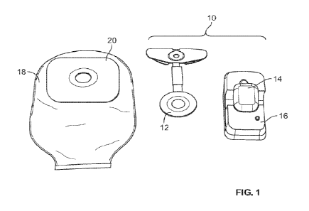
[0063] FIG. 1 shows an ostomy leakage detection system
10 according
to an embodiment. The ostomy leakage detection system 10 may generally
comprise
a sensing accessory 12, a wearable subsystem 14, a charging dock 16, and a
mobile
application (not shown). The sensing accessory 12 may be configured as an
ostomy
accessory that can be attached to an ostomy skin barrier, for example, an
ostomy
11
CA 03175645 2022- 10- 14
WO 2021/242603
PCT/US2021/033417
barrier of a one-piece pouch system or a faceplate for a two-piece pouch
system. A
one-piece ostomy pouch system 18 comprising an ostomy barrier 20 according to
an
embodiment is shown in FIG. 1.
[0064] Sensing Accessory
[0065] The sensing accessory may be configured to
detect an ostomy
effluent leakage by providing sensors at a site of leakage under an ostomy
barrier.
The sensing accessory may comprise a plurality of sensors configured to detect
the
presence of fluid. The plurality of sensors may include conductivity sensors,
thermistors, or other sensors. In an embodiment, the sensing accessory may
comprise
a plurality of conductivity sensors formed from conductive traces arranged in
close
proximity. The conductive traces are also referred to herein as electrodes.
When
fluid bridges the conductive traces or saturates an adjacent hydrocolloid
adhesive, a
change in conductivity may be measured, which may be used to determine an
ostomy
effluent leakage. The sensors may be disposed on a circuit substrate. The
circuit
substrate may be configured to provide a suitable mechanical support to
preserve the
conductivity of the traces.
[0066] The conductive traces may be formed by printing
a circuit
substrate using a conductive ink via a conventional printing process, for
example,
screen printing. The conductive ink may comprise carbon black, graphite,
silver(Ag),
or a silver and silver chloride blend (Ag/AgC1). Each of the plurality of
conductive
traces may have a width and arranged spaced apart from each other. The
parameters
of the conductive traces may be configured to provide a particular resistance
of a
sensor circuit.
100671 In an embodiment, the sensing accessory may be
configured to
detect a leakage based on a change in resistance across a pair of conductive
traces
making up a sensor. FIG. 2 is a schematic cross-sectional illustration of two
pairs of
conductive traces configured to measure resistance of a skin barrier adhesive,
wherein
R1 is resistance between a first pair of conductive traces and R2 is
resistance between
a second pair of conductive traces. In the embodiment of FIG. 2, the leakage
detection system may be configured to determine a leakage event from a
decrease in
resistance R2 between the second pair of conductive traces upon exposure to
ostomy
effluent.
[0068] FIG. 3 is a graph displaying resistance data
collected from a
sensing accessory comprising a plurality of sensors according to an
embodiment,
12
CA 03175645 2022- 10- 14
WO 2021/242603
PCT/US2021/033417
wherein a drop of resistance is recorded at multiple sensors as a leakage
progresses
outward and contacts different sensors. As shown, the resistance drops from a
value
exceeding a measurement range of a processor (> 2 Mil) to very low
(approximately
1 ki)). this embodiment, the resistance of the sensors may be
negligible when
compared to the large magnitude of a resistance change upon exposure to ostomy
fluid. Thus, the sensors for the sensing accessory may be formed from
conductive
traces of various thicknesses and arrangements as long as the resistance of
the
conductive trace is low relative to the baseline (dry) resistance between the
conductive traces.
[0069] In an embodiment, the sensing accessory 12 may
include a
plurality of conductive traces as shown in FIG. 4 and FIG. 5A-5C. Each of the
conductive traces may be configured to have a width of about 0.002 inches and
arranged spaced apart from each other with a gap of about 0.002 inches. In
other
embodiments, the conductive traces may be configured wider or narrower and
arranged in various configurations. In an embodiment, the gap between the
conductive traces may be about 0.01 inches. In an embodiment, a plurality of
radially
spaced layers of conductive traces may be configured and arranged to fit
within a
space defined by an ostomy pouch system barrier.
[0070] The sensing accessory 12 may comprise a
plurality of sensors
formed from a plurality of substantially elliptical conductive traces arranged
around a
center opening for receiving a stoma_ "Substantially elliptical conductive
traces" as
used herein include conductive traces having various elliptical shapes, such
as
circular, oval, etc. Each of the plurality of sensors may be arranged at
different radial
distances from the center opening. Each sensor may cover a portion of the area
surrounding the central opening. In the embodiment of FIG 4 and FIGS. 5A-5C,
the
sensors may be arranged in five layers at different radial distances. Four
sensor layers
are labeled Li, L2, L3, and L4 as best shown in FIGS. 5A and SC. Each of the
four
layers Li, L2, L3, and L4 may be configured to substantially surround the
center
opening, such that a leakage in any radial direction may be detected. The
plurality of
sensors may also include three ground traces Gl, G2, G3, wherein G1 is
arranged
between Ll and L2, G2 is arranged between a fifth sensor and L3, and G3 is
arranged
adjacent L4 as best shown in FIGS. 5A and 5C. In such an embodiment, the
sensing
accessory 12 may be configured to measure resistance between Li and G1 (first
level
13
CA 03175645 2022- 10- 14
WO 2021/242603
PCT/US2021/033417
sensor), between L2 and GI (second level sensor), between G2 and L3 (third
level
sensor), and between L4 and G3 (fourth level sensor).
[0071] In this embodiment, the fifth sensor layer may
be arranged
between L2 and G2 and may be subdivided into four quadrants SW, NW, NE, and
SE,
which corresponds to intercardinal directions with a tail of the sensing
accessory 12
oriented at South as shown in FIGS. 5A and 5C. The four quadrants may be
evenly
spaced at about 90 degrees, each quadrant covering about quarter of the area
around
the center opening. In this embodiment, a lower portion of NW sensor (LNW), a
lower portion of NE sensor (LNE), and tail portions of the sensors and ground
traces
may be covered with a masking layer as best shown in FIG. 5B. In other
embodiments, the fifth layer may comprise more than four or less than four
subdivisions and/or unevenly divided subdivisions. The fifth sensor layer
comprising
subdivided sensor sections may be configured to detect a radial direction of a
leakage
according to a change in resistance measured at one or more of the
subdivisions. The
sensors arranged at different radial distances may be configured to track a
progression
of ostomy effluent leakage. By only subdividing some layers, the total number
of
sensors may be reduced while preserving the location-detection function.
[0072] In an embodiment, the conductive traces may be
printed on a
circuit substrate using a conductive ink. Suitable materials for the circuit
substrate
may include, but are not limited to polyester (PET), polyethylene (PE).
polyurethane
film (PU), or thermoplastic polyurethane (TPU) film. The circuit substrate may
be
configured to provide an excellent bonding surface for the conductive ink,
prevent
mechanical damage to the conductive ink, and adhere to hydrocolloid adhesive
layer.
In some embodiments, the circuit substrate and the conductive ink may be
configured
to provide at least some degree of elasticity to allow stretching of the
sensing
accessory 12. In an embodiment, the sensing accessory 12 may comprise a PET
circuit substrate having a thickness of about 0.001 inches to about 0.010
inches,
preferably about 0.003 inches.
[0073] In some embodiments, the sensing accessory 12
may include
masking layers covering some portions of the conductive traces. The masking
layers
may be formed from a film or a masking material. The masking layer may be
configured to prevent bridging of the conductive traces by fluid in the
covered
portions. In an embodiment, a making layer may cover a tail region of the
conductive
traces. The making layer may extend into a portion of sensors and connector
regions.
14
CA 03175645 2022- 10- 14
WO 2021/242603
PCT/US2021/033417
In the embodiment of FIGS. 5A-5C, lower portions of the NW and NE sensors
(LNW, LNE) may be covered by masking layers, which allows for leakage
detection
only in the exposed portions of the sensors. The tail portion may be masked to
prevent false leak detection resulting from sensors being bridged by fluid
outside of
an ostomy skin barrier area. FIG. 5A illustrates exposed portions of the
conductive
traces of the sensing accessory 12, while FIG. 5B illustrates masked portions
of the
conductive traces. In some embodiments, the masking layer may be configured to
promote adhesion between a hydrocolloid adhesive layer of a skin barrier and
the
sensing accessory 12.
[0074] The sensing accessory 12 may be configured to
be compatible
with existing ostomy appliances and to adapt to various stoma sizes and
shapes. A
center opening of the sensing accessory 12 may be configured to align with an
opening in an ostomy barrier to receive a stoma. When the sensing accessory 12
is
placed on the ostomy barrier, a backing layer of the sensing accessory may be
attached to a hydrocolloid layer of the ostomy barrier. The backing layer may
be
formed from a suitable material, such as an adhesive, a dead-stretch film,
etc. The
backing layer may be configured to allow a user to adapt the shape of the
center
opening, for example, by cutting or molding, to fit a stoma. The backing layer
may be
provided with labels to guide and limit cutting or shaping of the sensing
accessory 12
to prevent damaging of the sensing accessory circuitry.
[0075] In some embodiments, the sensing accessory 12
may be
configured to be molded to conform to the convexity of a convex ostomy
barrier. In
an embodiment, the sensing accessory 12 may comprise a stretchable printed
circuit
system to conform to a convex ostomy barrier. In such an embodiment, a circuit
substrate, printed conductive traces, and masking layers may be formed from
stretchable materials, such as the Dupont INTEXAR system. In another
embodiment,
the sensing accessory may include slits and voids configured and arranged in a
non-
stretchable circuit substrate, such as PET, to conform the sensing accessory
to a
convex barrier.
[0076] The sensing accessory 12 may include a
hydrocolloid adhesive
layer to provide an interface between an ostomy pouch system and user's skin.
The
adhesive may be configured similar to known hydrocolloid adhesives on ostomy
products ¨ e.g. absorbing fluid while maintaining adhesion to the skin. The
adhesive
may be configured to change conductivity upon exposure to fluid to enable
leakage
CA 03175645 2022- 10- 14
WO 2021/242603
PCT/US2021/033417
detection by measuring the conductivity or resistance of the adhesive. In an
embodiment, the sensing accessory 12 may include a hydrocolloid adhesive layer
configured to exhibit a resistance drop from greater than 2 1\41-2 to about 1
1(11 when
the hydrocolloid adhesive layer absorbs ostomy effluent. The adhesive may also
be
configured to have other desirable properties, such as pH balancing or
infusion of
skin-friendly ingredients.
[0077] The adhesive layers of the sensing accessory 12
may be
covered by release liners. The release liner may be formed from a silicone-
coated
film and may include a tab to facilitate removal. In an embodiment, the
sensing
accessory 12 may include two release liners, each covering opposing surfaces
of the
sensing accessory 12. The release liners may be arranged such that the release
liner
tabs may be offset as shown in FIG. 6. Alternatively, the release liners may
be
arranged such that the tabs may be aligned, wherein one tab may be bigger than
the
other to facilitate a correct order of removal. In the embodiment of FIG. 6,
the release
liners may be labeled to guide a user through removal of the release liners,
assembling
of the sensing accessory with an ostomy pouch system, and attaching the
assembled
sensing accessory and ostomy pouch system to user's body.
[0078] The sensing accessory 12 may be manufactured
through
progressive assembly of constituent materials. At least some of the materials,
for
example, a circuit substrate, tail cover, release liners, etc., may be
provided in a roll
form and processed and cut into shape, for example, by die-cutting, for
assembly.
The hydrocolloid adhesive may be extruded into a roll having a specified
thickness,
which may be cut in line and assembled. Alternatively, the hydrocolloid
adhesive
may be molded on top of the assembled circuit, then cut to shape.
[0079] The sensing accessory 12 may be coupled to the
wearable
subsystem 14. The conductive traces, which form the sensors, may extend beyond
the
periphery of an ostomy skin barrier and to a connector region configured to
engage
the wearable subsystem 14. The portion of the sensing accessory 12 that
extends
between a sensor region and the connector region is referred to herein as a
tail or tail
region as shown in FIGS. 4 and 7. Selecting a flexible substrate for the
sensing
accessory 12 may allow a user to position the wearable subsystem 14 in a
variety of
locations on their skin, ostomy pouch, or clothing.
[0080] A layout of the terminating sections of the
conductive traces
may be configured to correspond to conductive connecting sections of the
wearable
16
CA 03175645 2022- 10- 14
WO 2021/242603
PCT/US2021/033417
subsystem 14. This allows an electrical connection to be formed between the
conductive traces of the sensing accessory 12 and a processor of the wearable
subsystem 14. FIGS. 5A, 5B and 7 illustrate an embodiment of a sensing
accessory
connector region comprising two openings in the substrate, which function as
alignment members corresponding to raised alignment members of a wearable
subsystem 14. The alignment members may be configured to facilitate correct
alignment and connection between the sensing accessory 12 and the wearable
subsystem 14.
[0081] FIG. 7 shows an exploded view of the sensing
accessory 12
according to an embodiment. The sensing accessory 12 may generally comprise an
adhesive layer 13, a sensor layer 15 and a barrier-side layer (also referred
to herein as
a backing layer) 17. A center opening 19 configured to receive a stoma may
extend
through the sensing accessory 12. The center opening 19 may be formed by
respective openings provided in individual layers of the sensing accessory 12.
Each
layer 13, 15, 17 of the sensing accessory 12 may have a proximal side and a
distal
side. When the sensor accessory 12 is attached to a user, the respective
proximal
sides generally face the user and the respective distal sides generally face
away from
the user.
[0082] The adhesive layer 13 may be disposed on a body-
side of the
sensing accessory 12. In an embodiment, the proximal side of the adhesive
layer 13
may form at least a portion of the body-side surface of the sensor accessory
12. The
proximal side of the adhesive layer 13 may be configured to adhere to the
peristomal
skin surface of a user and seal around the stoma. The adhesive layer 13 may be
formed from a medical-grade pressure sensitive adhesive that can adhesively
secure
the sensing accessory 12 to the user. In an embodiment, the adhesive layer 13
may be
formed from a hydrocolloid adhesive. A release liner 21 may be provided on the
proximal side of the adhesive layer 13 to cover the adhesive, which may be
removed
before attaching the sensing accessory 12 to user's skin.
[0083] The barrier-side layer 17 may be formed from a
flexible
material that is generally soft and non-irritable to user's skin, such as an
adhesive,
polymeric film, nonwoven or foam material. In an embodiment, the barrier-side
layer
17 may be formed from an adhesive, such as a hydrocolloid adhesive. In such an
embodiment, a release liner 22 may be provided on the distal side of the
barrier-side
17
CA 03175645 2022- 10- 14
WO 2021/242603
PCT/US2021/033417
layer 17 to cover the adhesive, which may be removed before applying the
sensing
accessory 12 to an ostomy barrier or faceplate.
[0084] The sensor layer 15 may include sensors formed
from an
electrically conductive circuitry 24, such as a plurality of electrodes,
conductive traces
or the like. The electrically conductive circuitry 24 may be disposed on a
circuit
substrate 26. In an embodiment, the sensor layer 15 may include a sensor
region 28, a
connector region 30 and a tail region 32 arranged therebetween. The
electrically
conductive circuitry 24 may be arranged in a predetermined pattern in the
sensor
region 28. For example, the electrically conductive circuitry 24 may be
generally
arranged in a circular or semi-circular pattern. Other suitable patterns are
envisioned
as well, such as an oval or oblong pattern, or other closed or substantially
closed loop
pattern. The electrically conductive circuitry 24 in the sensor region 28 may
be
arranged at one or more radial distances from the center opening 19. For
example, the
conductive circuitry 24 may comprise a plurality of electrically conductive
traces
arranged at a plurality of different, radial distances from the center opening
19.
[0085] In an embodiment, the tail region 32 may
generally be formed
as an elongated section extending from the sensor region 28 to the connector
region
30. The tail region 32 may extend beyond an outer periphery of the first
adhesive
layer 13 and/or the barrier-side layer 17 in a direction radially outward from
the center
opening 19. The electrically conductive circuitry 24 may extend along the tail
region
32. in an embodiment, the tail region 32 may be flexible along at least a
portion of its
length such that it may be folded or wrapped.
[0086] The connector region 30 may include a plurality
of connection
points 34 electrically connected to the conductive circuitry 24. The
connection points
34 may include an externally accessible portion configured for electrical
connection
to an external device, such as the wearable subsystem 14. In this manner, the
connection points 34 may provide an electrical connection between the wearable
subsystem 14 and the electrically conductive circuitry 24. The externally
accessible
portion of the connection points 34 may be any suitable electrical interface
for
forming an electrical connection between two electrical components, such as
one or
more electrically conductive contacts, pins, and the like.
[0087] The connector region 30 may also include one or
more
alignment members 36. The one or more alignment members 36 may be configured
to engage corresponding alignment members of the wearable subsystem 14 to
18
CA 03175645 2022- 10- 14
WO 2021/242603
PCT/US2021/033417
facilitate positioning of the connector region 30 relative to the wearable
subsystem 14
to ensure electrical connection therebetween. In an embodiment, the one or
more
alignment members 36 of the connector region 30 may be an opening, recess or
slot.
The corresponding alignment members of the wearable subsystem 14 may be one or
more projections configured for receipt in the opening, recess or slot of the
connector
region 30.
[0088] In an embodiment, the sensing accessory 12 may
be configured
to detect a leakage by measuring resistance between electrodes. For example,
the
sensing accessory 12 may be configured to detect a change in resistance
between
electrodes triggered by ostomy effluent bridging the electrodes as a leakage
propagates. In the embodiment of FIG. 7, the electrically conductive circuitry
24 may
comprise a plurality of electrodes arranged on the proximal side of the sensor
region
28, such that the electrodes may be positioned adjacent and in contact with
the
adhesive layer 13 to measure resistance of the adhesive layer 13. The
plurality of
electrodes 24 may extend along the proximal side of the tail region 32 and
along a
portion of the connector region 30 to the connection points 34. In such an
embodiment, a masking element may be used to prevent shorting between
electrodes
in the areas where detection is not desired. For example, a masking element 38
may
be provided on the body-side of the sensing accessory 12 to cover the
plurality of
electrodes 24 in the tail region 32.
[0089] FIG. 22 is a schematic illustration of the
sensing accessory 12
attached to an ostomy barrier 20 and fitted around a stoma 2 according to an
embodiment. The sensing accessory 12 may be configured such that a first
conductive trace or electrode 25 of the electrically conductive circuitry 24
may be
arranged adjacent a center opening 19 with a minimum space therebetween of
about
0.25 inches to allow for fitting around the stoma 2 without damaging the
electrically
conductive circuitry 24.
[0090] FIGS. 8 and 9 illustrate a sensing accessory
112 according to
another embodiment. The sensing accessory 112 may be configured similar to the
sensing accessory 12, generally comprising an adhesive layer 113, a sensor
layer 115
and a barrier-side layer 117. The adhesive layer 113 may be formed from a
hydrocolloid adhesive and disposed on a body-side of the sensing accessory 112
for
attachment to a user. A release liner 121 including a tab 123 may be provided
on the
proximal side of the adhesive layer 113. The barrier-side layer 117 may be
formed
19
CA 03175645 2022- 10- 14
WO 2021/242603
PCT/US2021/033417
from an adhesive, and a release liner 122 including a tab 125 may be provided
on a
distal side of the barrier-side layer 117. The release liners 121, 122 may be
arranged
such that the tabs 123, 125 are offset from each other as best shown in FIG.
8.
Indicator labels 127, 129 may be provided on each side of the sensing
accessory 112
to guide assembling of the sensing accessory 112 with an ostomy appliance and
attachment of the same to a user.
[0091] The sensor layer 115 may comprise a generally
ring-shaped
sensor region 128, a connector region 130 and a tail region 132 connecting the
sensor
region 128 and the connector region 130. The sensor region 128 may comprise
sensors formed from an electrically conductive circuitry 124, which may extend
through the tail region 132 and to connection points 134 in the connector
region 130.
The tail region 132 may be formed as an elongated section extending between
the
sensor region 128 and the connector region 130. The connection points 134 may
be
configured to electrical connect the sensing accessory 112 to an external
device, such
as the wearable subsystem 14. The exposed portions of the tail region 132 that
are not
covered by the adhesive layer 113 and the barrier-side layer 117 may be
covered by
tail covers 135, 137.
[0092] FIG. 10 illustrates an electrically conductive
circuitry 224
arranged on a proximal side of the sensor region 128 according to an
embodiment.
The electrically conductive circuitry 224 may comprise a plurality of
substantially
circular conductive traces, also referred to herein as circular electrodes,
Li, L2, L4,
L5, Gl, G2, G3, and a plurality of arc shaped conductive traces, also referred
to
herein as electrode arcs, Q1, Q2, Q3, Q4. Each of the circular electrodes may
be
arranged at a different radial distance from a center opening 119 and
configured to
determine a radial progress of ostomy effluent leakage.
[0093] In this embodiment the electrically conductive
circuitry 224
may include four electrode arcs arranged in different sections of the sensor
region 128
to determine a location of a leak in the sensor region 128. A first electrode
arc Q1
may be arranged to extend along a southeast (SE) quadrant of the sensor region
128.
A second electrode arc Q2 may be arranged to extend along an east half of the
sensor
region 128, wherein a lower portion of the second electrode arc Q2 that
extends
adjacent the first electrode arc Q1 may be covered with a making layer
(similar to the
masked LNE shown in FIG. 5B), such that the exposed portion the second
electrode
arc Q2 only extends along a northeast (NE) quadrant of the sensor region 128.
A
CA 03175645 2022- 10- 14
WO 2021/242603
PCT/US2021/033417
third electrode arc Q3 may be arranged to extend along a west half of the
sensor
region 128, wherein a lower portion of the third electrode arc Q3 that extends
adjacent
a fourth electrode arc Q4 may be covered with a making layer (similar to the
masked
LNW shown in FIG. 5B), such that the exposed portion the third electrode arc
Q3
only extends along a northwest (NW) quadrant of the sensor region 128. The
fourth
electrode arc Q4 may be arranged to extend along a southwest (SW) quadrant of
the
sensor region 128. In this embodiment, a change in electrical resistance
measured by
one of the four electrode arcs may be used to determine the location of a
leakage. In
other embodiments, the electrically conductive circuitry 224 may include less
than
four electrode arcs or more than four electrode arcs, which may be arranged in
different sections of the sensor region 128 and configured to identify a
leakage
location.
[0094] In the embodiment of FIG. 10, the circular
electrodes may
comprise four level sensors Li, L2, L4, L5 and three ground electrodes Gl, G2,
G3,
wherein resistance measured between a level sensor and a ground electrode may
be
analyzed to determine a leakage. In this embodiment, first and second level
sensors
Li, L2 may share a first ground electrode G I, wherein resistance measured
between a
first lever sensor Ll and the first ground electrode GI may be analyzed to
determine a
level 1 leakage, and resistance measured between the first ground electrode G1
and a
second level sensor L2 may be analyzed to determine a level 2 leakage. A
second
ground electrode G2 may be shared between the electrode arcs Q1 , Q2, Q3, Q4
and a
fourth level sensor L4, wherein resistance measured between the electrode arcs
Ql,
Q2, Q3, Q4 and the second ground electrode G2 may be analyzed to determine a
level
3 leakage at a specific quadrant, and resistance measured between the second
ground
electrode G2 and the fourth level sensor L4 may be analyzed to determine a
level 4
leakage. A level 5 leakage, which is the most critical leakage level in this
embodiment, may be determined by analyzing resistance measured between a fifth
level sensor L5 and a third ground electrode G3.
[0095] FIG. 11 illustrates an electrically conductive
circuitry 324
arranged on a proximal side of the sensor region 128 according to another
embodiment. The electrically conductive circuitry 324 may comprise a plurality
of
substantially circular conductive traces Cl, C2, C3, C4, and a plurality of
arc shaped
conductive traces Ql, Q2, Q3, Q4. In this embodiment the electrically
conductive
circuitry 324 may include four electrode arcs arranged in different sections
of the
21
CA 03175645 2022- 10- 14
WO 2021/242603
PCT/US2021/033417
sensor region 128 to determine a location of a leak in the sensor region 128.
A first
electrode arc Q1 may be arranged to extend along a SE quadrant of the sensor
region
128. A second electrode arc Q2 may be arranged to extend along an east half of
the
sensor region 128, wherein an upper portion Q2U extends along a NE quadrant of
the
sensor region 128 and a lower portion Q2L, which may be masked, extends along
a
SE quadrant of the sensor region 128. A third electrode arc Q3 may be arranged
to
extend along a west half of the sensor region 128, wherein an upper portion
Q3U
extends along a NW quadrant of the sensor region 128 and a lower portion Q3L,
which may be masked, extends along a SW quadrant of the sensor region 128. A
fourth electrode arc Q4 may be arranged to extend along a southwest (SW)
quadrant
of the sensor region 128.
[0096] In this embodiment, a change in resistance
measured between a
first circular electrode Cl and a second circular electrode C2 may be analyzed
to
determine a level 1 leakage. A change in resistance measured between the
second
circular electrode C2 and the first electrode arc Q1 may be analyzed to
determine a
level 2 leakage in the SE quadrant. A change in resistance measured between
the
second circular electrode C2 and the upper portion of the second electrode arc
Q2U
may be analyzed to determine a level 2 leakage in the NE quadrant. A change in
resistance measured between the second circular electrode C2 and the upper
portion
of the third electrode arc Q3U may be analyzed to determine a level 2 leakage
in the
NW quadrant. A change in resistance measured between the second circular
electrode
C2 and the fourth electrode arc Q4 may be analyzed to determine a level 2
leakage in
the SW quadrant. A change in resistance measured between the first electrode
arc Q1
and a third circular electrode C3 may be analyzed to determine a level 3
leakage in the
SE quadrant, wherein a detection algorithm may set a higher threshold for
leakage
detection to compensate for a greater distance between the first electrode arc
Q1 and
the third circular electrode C3. A change in resistance measured between the
upper
portion of the second electrode arc Q2U and the third circular electrode C3
may be
analyzed to determine a level 3 leakage in the NE quadrant. A change in
resistance
measured between the upper portion of the third electrode arc Q3U and the
third
circular electrode C3 may be analyzed to determine a level 3 leakage in the NW
quadrant. A change in resistance measured between the fourth electrode arc Q4
and
the third circular electrode C3 may be analyzed to determine a level 3 leakage
in the
SW quadrant, wherein a detection algorithm may set a higher threshold for
leakage
22
CA 03175645 2022- 10- 14
WO 2021/242603
PCT/US2021/033417
detection to compensate for a greater distance between the first electrode arc
Q4 and
the third circular electrode C3. A change in resistance measured between the
third
circular electrode C3 and a fourth circular electrode C4 may be analyzed to
determine
a level 4 leakage.
[0097] Wearable Subsystem
[0098] The wearable subsystem 14 may function as a
relay between
the sensing accessory 12 and a user or other subsystems of the leakage
detection
system 10. The wearable subsystem 14 may be configured to physically and
electronically connect to the sensing accessory 12 and receive and analyze
signals
from the sensing accessory 12. The wearable subsystem 14 according to an
embodiment is shown in FIGS. 12 and 13. The wearable subsystem 14 may comprise
a hinged case, an imbedded circuit board, a battery, a motor, and alignment
members
40 that correspond to alignment members 36 of the sensing accessory 12. The
circuit
board may include conductive members 24 configured to contact terminal ends of
sensing traces of the sensing accessory 12, such as the connecting points 34
(FIG. 7).
In this embodiment, the conductive members 24 comprising a plurality of raised
conductive pads may be arranged generally in a center area of a bottom housing
of the
wearable subsystem 14.
[0099] The alignment members 40 may comprise two
raised members,
each of which may be arranged on each side of the conductive members 24 as
shown
in FIG 12. In such an embodiment, the alignment members 36 of the sensing
accessory 12 may be defined by two openings in the connector region 30, which
may
be configured to receive the raised alignment members 40 of the wearable
subsystem
14. The alignment members 36, 40 may be configured to facilitate correct
attachment
of the wearable subsystem 14 to the sensing accessory 12 to ensure electrical
connection therebetween. A user may form a connection between the sensing
accessory 12 and the wearable subsystem 14 by aligning the corresponding
alignment
members 36, 40 as shown in FIG. 13 and closing the wearable subsystem 14.
[00100] The circuit board of the wearable subsystem 14
may include a
processor and other components to analyze signals received from the sensing
accessory 12, communicate with external devices, such as a mobile device and a
charging dock 16, and alert a user vis sound, vibration, LEDs, etc. to notify
a system
status. FIG. 14 is an exploded view of a wearable subsystem 14 according to an
embodiment.
23
CA 03175645 2022- 10- 14
WO 2021/242603
PCT/US2021/033417
[00101] In an embodiment, the wearable subsystem 14 may
be secured
to an ostomy pouch 18 or user via adhesive pads 39 attached to the sensing
accessory
12 as shown in FIG. 15. The adhesive pads 39 may be covered with release
liners,
which may be removed before use.
[00102] FIGS. 16 and 17 show a wearable subsystem 114
according to
another embodiment. The wearable subsystem 114 may be configured similar to
the
wearable subsystem 14, generally comprising a hinged case, an imbedded circuit
board, a battery, a motor, and an alignment member 140 that correspond to an
alignment member 136 of the sensing accessory 112. The circuit board may
include
conductive members 124 configured to contact the connecting points 134 of the
sensing accessory 112.
[00103] In this embodiment, the wearable subsystem
alignment
member 140 may comprise a center raised key member 141 and a peripheral raised
member 143. The center raised key member 141 may be arranged generally in the
center of a bottom housing of the wearable subsystem 114, while the peripheral
raised
member 143 may be arranged proximate a hinge 145. The alignment member 136 of
the sensing accessory 112 may be defined by openings in the connector region
130,
which may be configured to receive the raised alignment member 140 of the
wearable
subsystem 14. In this embodiment, the alignment member 136 may include a
center
key opening 138 configured to receive the center raised key member 141 and a
peripheral opening 139 configured to receive the peripheral raised member 143_
The
alignment members 136, 140 may be configured to facilitate correct attachment
of the
wearable subsystem 114 to the sensing accessory 112 to ensure electrical
connection
therebetween. In an embodiment, the wearable subsystem 114 may be attached to
an
ostomy pouch or user via an adhesive pad 102 as shown in FIGS. 18-21.
[00104] During use, the wearable subsystem 14, 114 may
poll
resistance measurements from conductive traces to collect resistance data,
which may
be processed through an algorithm for determining an ostomy effluent leakage
event.
The algorithm may consider resistance measurements and other factors, such as
resistance measurements from neighboring conductive traces, a change in
resistance
from recent prior resistance measurements, historical data from prior uses,
etc.
[00105] Upon a detection of an ostomy effluent leakage
event, the
wearable subsystem 14, 114 may alert a user via sound, vibration, light, etc.
according
the leakage event. An alert may be sent based on resistance measurements
received
24
CA 03175645 2022- 10- 14
WO 2021/242603
PCT/US2021/033417
from multiple sensors, patterns in measurements, user preference inputs,
signals
received from other components of the ostomy leakage detection system, such as
a
mobile application and/or charging dock.
[00106] The wearable subsystem 14, 114 may be
configured to
communicate data to a mobile application. The data may be raw sensor data as
received from the sensing accessory 12, 112 or processed data processed by the
wearable subsystem 14, 114, which may include a summarized data and/or a
leakage
event information. The wearable subsystem 14, 114 may also be configured to
communicate system conditions, such as the connectivity of the sensing
accessory 12,
112, a faulty sensor, a state of battery, etc. The wearable subsystem 14, 114
may be
powered by a battery or recharged by the charging dock 16. The wearable
subsystem
14, 114 may include conductive pads on a charge circuit portion of the circuit
board,
which may be configured to contact pins on the charging dock 16.
[00107] Charging Dock
[00108] A charging dock 16 according to an embodiment
is shown in
FIGS. 23A-D. The charging dock 16 may comprise a medical grade power supply
unit and a housing including charging pins 52 for electronically connecting to
the
wearable subsystem 14, 114. The housing may also include additional
components,
for example, a speaker and LEDs for sending alerts and feedback to a user, and
a
wireless communication module for communicating with the wearable subsystem
14,
114 and a mobile application
[00109] The charging dock 16 may be configured to
recharge a
rechargeable battery of the wearable subsystem 14, 114. When the wearable
subsystem 14, 114 is placed in a recessed area 54 of the charging dock 16, an
electrical connection may be formed between the charging pins 52 and
conductive
pads of the wearable subsystem 14, 114. A charging circuit of the wearable
subsystem 14, 114 may be configured to ensure a safe recharge.
[00110] In an embodiment, the charging dock 16 may be
configured to
provide an additional means for alerting a user about leakage events. When the
charging dock 16 is in wireless communication with the wearable subsystem 14,
114,
the user may have an option to receive leak alerts from the charging dock 16.
This
option may be most advantageous at night when other means of alerting may not
be as
effective for users during sleep. For example, a vibration alert from the
wearable
subsystem 14, 114 may not be effective to rouse a sleeping user. The user may
also
CA 03175645 2022- 10- 14
WO 2021/242603
PCT/US2021/033417
power down or disable sounds from a mobile phone at night. As such, the user
may
opt to receive alerts from the charging dock 16. The wearable subsystem 14,
114 may
be configured to determines a leakage event and send a signal to the charging
dock 16
via Bluetooth communication. The charging dock 15 may be configured to send an
audible alert through a speaker and/ or a visual alert through LEDs when a
leakage
event signal is received. Certain aspects of the alert, such as volume and
duration,
may be configurable by the user.
[00111] Mobile Application
[00112] The mobile application may be configured to
provide means for
users to interact with the ostomy leakage detection system 10. For example, a
user
may set preferences for alerts and review historical data, such as analysis of
leakage
patterns and usage trends, by using the mobile application. The mobile
application
may also be configured to functions as a resource for connecting the user to
support,
such as training materials, experts at the manufacturer, and ostomy
clinicians.
[00113] The mobile application may be configured to
communicate
with the wearable subsystem 14, 114 and the charging dock 16 over Bluetooth.
The
mobile application may be configured to confirm these connections and alerts
if a
subsystem is unavailable. The mobile application may be configured to alert
the user
about leakage events and/or system issues through alert functions of a mobile
phone,
such as sound and vibration.
[00114] The mobile application may be configured to
relay data to a
cloud server for storage and/or data analysis, for example prediction of leaks
based on
repeated wears, comparison to the leakage patterns of other users of the
system, or
other factors. A communication link between a cloud system and the mobile
application may allow for additional features, such as product recommendations
based
on leakage patterns or other data, re-ordering of products in a convenient or
automatic
format, direct consultation with a clinician, storage of photographs of the
stoma or
peristomal skin for tracking alongside leakage patterns, etc.
[00115] A diagram of communication between subsystems
of the
ostomy leakage detection system 10 and communication between the ostomy
leakage
detection system 10 and a cloud system according to an embodiment is shown in
FIG.
25.
[00116] Method of detecting ostomy effluent leakage
26
CA 03175645 2022- 10- 14
WO 2021/242603
PCT/US2021/033417
[00117] The sensing accessory 12, 112 may be configured
to detect an
ostomy effluent leakage by measuring a change in resistance between
electrodes,
which are also referred to herein as conductive traces. When ostomy effluent
bridges
two electrodes, a resistance measurement between the electrodes may drop
substantially to indicate a leakage event. In an embodiment, resistance below
a pre-
determined threshold resistance value of 1 MS2 may identify a leakage event,
which is
selected to provide a necessary level of sensitivity to distinguish an ostomy
effluent
leakage event from other events causing a change in resistance, for example,
user's
perspiration.
[00118] FIG. 24 is a block diagram for a method of
detecting an ostomy
effluent leakage using the ostomy leakage detection system 10 according to an
embodiment. The steps of the method of detecting an ostomy effluent leakage
may be
configured for accurate determination of leakage events and to minimize false
detections. The method may include the step of providing a sensing accessory
12,
112 comprising a plurality of sensors, for example, 8 sensors, arranged
adjacent an
adhesive or embedded in the adhesive. Each of the plurality of sensors may be
formed from a pair of conductive traces configured to measure resistance of
the
adhesive.
[00119] The method may also include the step of
determining whether
the sensing accessory 12, 112 is electrically connected to the wearable
subsystem 14,
114. In the step of "Is a sensor connected?" 400, the wearable subsystem 14,
114 may
send a signal to the sensing accessory 12, 112 requesting a return signal. If
no signal
is returned, the wearable subsystem 14, 114 may determine that the sensing
accessory
12, 112 is not connected and increase a disconnect timer in the step of
"Increment
disconnect timer" 402. The wearable subsystem 14, 114 may also send the
disconnect
timer data to an external device, such as user's phone, when the sensing
accessory 12,
112 is not connected to the wearable device 14, 114 in the step of "Push time
to
phone" 404.
[00120] When the wearable device 14, 114 detects the
sensing
accessory 12, 112, the wearable device 14, 114 may pull a resistance
measurement
signal from each sensor in the step of -Input signal from sensor (T=2s)" 406.
In an
embodiment, the wearable device 14, 114 may be configured to pull and receive
a
resistance measurement every 2 seconds. The signal received from each sensor
may
be processed separately in the step of "Enter for loop to evaluate each sensor
27
CA 03175645 2022- 10- 14
WO 2021/242603
PCT/US2021/033417
individually (sensor=1:8)- 408. The signals may be processed by a processor
provided in the wearable device 14, 114 to determine whether a resistance
measured
by a sensor is outside a predetermined range of acceptable resistance values
in the
step of "Are resistance values abnormal?" 410.
[00121] If the resistance measurement is outside the
predetermined
range of acceptable resistance values, for example, negative recorded
resistance
values, the sensor may be flagged in the step of "Increment sensor flag- 412.
In the
step of "Is sensor flag=5?" 414, the number of abnormal resistance
measurements that
fall outside the predetermined range of acceptable resistance values may be
counted.
If the number of abnormal resistance measurements reaches five, the wearable
device
14, 114 may determine that an abnormal event has occurred and may send an
alert to
an external device, such as user's phone, in the step of "Push to phone to
prompt user
to reconnect wearable- 416. The alert may also instruct a user to take an
action such
as reconnecting the wearable subsystem 14, 114 to the sensing accessory 12,
112.
[00122] In an embodiment, an abnormal resistance value
may not be
entered in a ring buffer, which is configured to store resistance
measurements, and a
new resistance measurement from the same sensor or a resistance measurement
from
a different sensor may be taken. If an issue is detected at a sensor in the
step of -Did
this sensor have an issue? (Flag=5)- 418, but the resistance measurements for
the
same sensor returns to a normal value within the predetermined range of
acceptable
resistance values for 10 subsequent consecutive seconds, the issue may be
cleared and
the resistance measurement data may be entered in the ring buffer in the steps
of "Has
data collection returned to normal values for 10 seconds?" 420, -Clear sensor
issue"
422, and "Ring buffer (n=5)" 424.
[00123] In an embodiment, the ring buffer may be
configured to hold a
current resistance measurement and four previous resistance measurements for
each
sensor, wherein the resistance measurements may be used to calculate a median
filter
value (a median of the five resistance measurements) in the step of "Median
filter"
426. The ring buffer may be continuously pushed through the median filter
which is a
median of the last five resistance measurements. In an embodiment, the
predetermined range of acceptable resistance values may be set at less than a
threshold resistance value of 1 MS2. In the step of "Is resistance <1000 kW"
428,
whether a median filter value of a sensor is less than the threshold value may
be
determined. If the median filter value of the sensor is less than the
threshold value,
28
CA 03175645 2022- 10- 14
WO 2021/242603
PCT/US2021/033417
the status of that sensor is checked in the step of "Is sensor in leak state?-
430. If the
sensor is not already in a leak state, a leak count of the sensor may be
incremented in
the step of "Increment Leak Count" 432. In the step of "Is leak count=3?" 434,
the
number of median filter values that are less than the threshold value may be
counted
(i.e. leak count). If the leak count of the sensor reaches three, the sensor
may be
determined to be in a leak state and an alert including information regarding
the leak
state, such as the location of the sensor, may be pushed to an external
device, such as
user's phone in the step of "Alert user of leak and sensor enters leak state"
436.
[00124] If the median filter value of the sensor is
determined to be
greater than or equal to the threshold value (1 MS2) in the step of "Is
resistance <1000
kg)?" 428, a resistance measurement from a next sensor is taken, and the steps
of
detecting an ostomy effluent leakage 408, 410, 412, 414, 416; 418, 420, 422,
424,
426, 428, 430, 432, 434, 436 may be repeated until resistance measurements
from all
of the sensors, for example eight sensors, are processed. If the median filter
values of
all of the sensors are determined to be greater than or equal to the threshold
value or
the maximum detectable resistance value, for example, 1541 knõ in the step of
"Are
all sensors >1000 kS2?" 438, the count of Clear for the sensors may be
increased in the
step of -Increment Clear variable" 440. If sensors are Clear for 5 consecutive
times in
the step of "Is Clear=5?", which may be 10 seconds in the embodiments wherein
the
resistance measurements are taken every 2 seconds, the sensors may be
determined to
be in a clear state and new resistance measurements are taken from the sensors
for a
next round of the leak detection analysis. If one or more sensors is
determined to be
in a leak state, leakage alerts may be cleared when a user changes the barrier
in the
step of "Assume barrier change and clear all alerts" 444.
[00125] From the foregoing it will be observed that
numerous
modifications and variations can be effectuated without departing from the
true spirit
and scope of the novel concepts of the present disclosure. It is to be
understood that
no limitation with respect to the specific embodiments illustrated is intended
or should
be inferred. The disclosure is intended to cover by the appended claims all
such
modifications as fall within the scope of the claims.
29
CA 03175645 2022- 10- 14