Note: Descriptions are shown in the official language in which they were submitted.
WO 2021/229606
PCT/IN2021/050463
AN AUTO-INJECTOR DEVICE FOR DELIVERING MEDICAMENTS
FIELD OF THE INVENTION
The present disclosure relates to medication delivery devices and more
particularly, to
an auto-injector device for delivering medicaments.
BACKGROUND
With the advancement in technology, various injection devices, such as manual
injection devices and auto-injector devices, are employed for administering
medicaments for
applications such as medical, therapeutic, diagnostic, pharmaceutical and
cosmetic.
Nowadays, users and healthcare professionals are more inclined towards using
the auto-
injector devices for administering medicaments. One of the prominent reasons
for such
inclination is a substantial reduction in the amount of training required for
using the auto-
injector devices.
Generally, an auto-injector device includes a prefilled syringe or cartridge
filled with a
specific volume of a medicament to be delivered to the user. A volume of the
medicament
filled in the auto-injector device depends on various parameters, such as a
type of medicament
and a medical condition of the user. Currently, the auto-injector device can
only be configured
to carry the specific volume of the medicament and fail to provide provisions
for varying the
volume of medicament without altering the constructional or operational
features of various
sub-components of the auto-injector device.
Hence, this may lead to a substantial reduction in the overall reusability of
the auto-
injector device for administering different types and doses of medicaments.
Further, the type
and dose of medicaments to be administered may act as design constraints for
the
manufacturing of the auto-injector devices. For instance, sub-components of
the auto-injector
devices are required to be manufactured based on the type of medicament and a
corresponding
dose of such medicament to be administered through the auto-injector device.
This may result
in a substantial increase in the overall manufacturing cost of the auto-
injector device.
SUMMARY
This summary is provided to introduce a selection of concepts, in a simplified
format,
that are further described in the detailed description of the invention. This
summary is neither
intended to identify key or essential inventive concepts of the invention and
nor is it intended
for determining the scope of the invention.
1
CA 03175677 2022- 10- 14
WO 2021/229606
PCT/IN2021/050463
In an embodiment of the present disclosure, an auto-injector device for
delivering
medicaments is disclosed. The auto-injector device includes a syringe assembly
having a
needle adapted to expel medicaments from the syringe assembly. The syringe
assembly
includes a barrel adapted to hold the medicaments and to be coupled to the
needle. A flow of
medicaments is directed out of the barrel through the needle. The syringe
assembly includes
a plunger positioned coaxially with respect to the barrel and adapted to
reciprocate within the
barrel to expel the medicaments from the barrel. Further, the syringe assembly
includes a
locking member adapted to be engaged with the plunger to hold the plunger in a
position with
respect to the barrel. The position of the plunger with respect to the barrel
is adapted to be
adjusted to vary a volume of medicaments to be expelled from the barrel. The
position of the
plunger is adjusted by engaging the locking member with the plunger at one of
a plurality of
positions along a length of the plunger.
To further clarify advantages and features of the present invention, a more
particular
description of the invention will be rendered by reference to specific
embodiments thereof,
which is illustrated in the appended drawings. It is appreciated that these
drawings depict only
typical embodiments of the invention and are therefore not to be considered
limiting of its
scope. The invention will be described and explained with additional
specificity and detail
with the accompanying drawings.
BRIEF DESCRIPTION OF THE DRAWINGS
These and other features, aspects, and advantages of the present invention
will become
better understood when the following detailed description is read with
reference to the
accompanying drawings in which like characters represent like parts throughout
the drawings,
wherein:
Figure 1 illustrates an auto-injector device and steps involved in the
implementation of
the auto-injector device for delivering medicament, according to an embodiment
of the
present disclosure;
Figure 2a illustrates a perspective view of the auto-injector device,
according to an
embodiment of the present disclosure;
Figure 2b illustrates an exploded view of the auto-injector device, according
to an
embodiment of the present disclosure;
Figures 3a and 3b illustrate sectional views of the auto-injector device,
according to an
embodiment of the present disclosure;
2
CA 03175677 2022- 10- 14
WO 2021/229606
PCT/IN2021/050463
Figure 4 illustrates a perspective view of a plunger of the auto-injector
device, according
to an embodiment of the present disclosure;
Figures 5a-5c illustrate operation of the auto-injector device for delivering
medicaments, according to an embodiment of the present disclosure; and
Figure 6 illustrates an enlarged sectional view of a portion A of the auto-
injector device
as shown in Figure 5c, according to an embodiment of the present disclosure.
Further, skilled artisans will appreciate that elements in the drawings are
illustrated for
simplicity and may not have been necessarily been drawn to scale. For example,
the flow
charts illustrate the method in terms of the most prominent steps involved to
help to improve
understanding of aspects of the present invention. Furthermore, in terms of
the construction
of the device, one or more components of the device may have been represented
in the
drawings by conventional symbols, and the drawings may show only those
specific details
that are pertinent to understanding the embodiments of the present invention
so as not to
obscure the drawings with details that will be readily apparent to those of
ordinary skill in the
art having benefit of the description herein.
DETAILED DESCRIPTION OF FIGURES
For the purpose of promoting an understanding of the principles of the
invention,
reference will now be made to the embodiment illustrated in the drawings and
specific
language will be used to describe the same. It will nevertheless be understood
that no
limitation of the scope of the invention is thereby intended, such alterations
and further
modifications in the illustrated system, and such further applications of the
principles of the
invention as illustrated therein being contemplated as would normally occur to
one skilled in
the art to which the invention relates. Unless otherwise defined, all
technical and scientific
terms used herein have the same meaning as commonly understood by one of
ordinary skilled
in the art to which this invention belongs. The system, methods, and examples
provided herein
are illustrative only and not intended to be limiting.
The term "some" as used herein is defined as "none, or one, or more than one,
or all."
Accordingly, the terms "none," "one," "more than one," "more than one, but not
all" or "all"
would all fall under the definition of "some." The term "some embodiments" may
refer to no
embodiments or to one embodiment or to several embodiments or to all
embodiments.
Accordingly, the term "some embodiments" is defined as meaning "no embodiment,
or one
embodiment, or more than one embodiment, or all embodiments."
3
CA 03175677 2022- 10- 14
WO 2021/229606
PCT/IN2021/050463
The terminology and structure employed herein is for describing, teaching and
illuminating some embodiments and their specific features and elements and
does not limit,
restrict or reduce the spirit and scope of the claims or their equivalents.
More specifically, any terms used herein such as but not limited to
"includes,"
"comprises," "has," "consists," and grammatical variants thereof do NOT
specify an exact
limitation or restriction and certainly do NOT exclude the possible addition
of one or more
features or elements, unless otherwise stated, and furthermore must NOT be
taken to exclude
the possible removal of one or more of the listed features and elements,
unless otherwise
stated with the limiting language -MUST comprise" or -NEEDS TO include."
Whether or not a certain feature or element was limited to being used only
once, either
way it may still be referred to as "one or more features" or "one or more
elements" or "at least
one feature" or "at least one element." Furthermore, the use of the terms "one
or more" or "at
least one" feature or element do NOT preclude there being none of that feature
or element,
unless otherwise specified by limiting language such as "there NEEDS to be one
or more . . .
"or "one or more element is REQUIRED."
Unless otherwise defined, all terms, and especially any technical and/or
scientific terms,
used herein may be taken to have the same meaning as commonly understood by
one having
an ordinary skill in the art.
Reference is made herein to some "embodiments." It should be understood that
an
embodiment is an example of a possible implementation of any features and/or
elements
presented in the attached claims. Some embodiments have been described for the
purpose of
illuminating one or more of the potential ways in which the specific features
and/or elements
of the attached claims fulfil the requirements of uniqueness, utility and non-
obviousness.
Use of the phrases and/or terms such as but not limited to "a first
embodiment," -a
further embodiment," "an alternate embodiment," "one embodiment," "an
embodiment,"
"multiple embodiments," "some embodiments," "other embodiments," "further
embodiment", "furthermore embodiment", "additional embodiment" or variants
thereof do
NOT necessarily refer to the same embodiments. Unless otherwise specified, one
or more
particular features and/or elements described in connection with one or more
embodiments
may be found in one embodiment, or may be found in more than one embodiment,
or may be
found in all embodiments, or may be found in no embodiments. Although one or
more features
and/or elements may be described herein in the context of only a single
embodiment, or
alternatively in the context of more than one embodiment, or further
alternatively in the
context of all embodiments, the features and/or elements may instead be
provided separately
4
CA 03175677 2022- 10- 14
WO 2021/229606
PCT/IN2021/050463
or in any appropriate combination or not at all. Conversely, any features
and/or elements
described in the context of separate embodiments may alternatively be realized
as existing
together in the context of a single embodiment.
Any particular and all details set forth herein are used in the context of
some
embodiments and therefore should NOT be necessarily taken as limiting factors
to the
attached claims. The attached claims and their legal equivalents can be
realized in the context
of embodiments other than the ones used as illustrative examples in the
description below.
Embodiments of the present invention will be described below in detail with
reference
to the accompanying drawings.
Figure 1 illustrates an auto-injector device 100 and steps involved in the
implementation of the auto-injector device 100 for delivering medicament,
according to an
embodiment of the present disclosure. In an embodiment, the auto-injector
device 100 may
be employed for delivering medicaments, interchangeably be referred to as
drugs, to a patient.
The auto-injector device 100 may include a proximal end 102 and a distal end
104. Further,
the auto-injector device 100 may include a cap 106 removably attached to the
distal end 104
of the auto-injector device 100. The cap 106 may be provided to protect a
needle of the auto-
injector device 100 and to restrict the ingress of any contaminants within the
auto-injector
device 100.
In order to implement the auto-injector device 100 for medication, referring
to Figure
1, at step 108, the cap 106 of the auto-injector device 100 may be removed for
delivering
medicaments to the patient. Subsequently, at step 110, the distal end 104 of
the auto-injector
device 100 may be placed on a site of injection corresponding to a
subcutaneous ( sub-Q)
region, on the patient for delivering the medicaments. Upon placing the auto-
injector device
100 on the site, the auto-injector device 100 may be pressed in a direction
towards the site of
injection and held for a predefined period of time for delivering the
medicaments to the patient
through the site. Subsequently, at step 112, the auto-injector device 100 may
be removed from
the site of injection and disposed in sharp collectors.
Constructional and operational details of the auto-injector device 100 are
explained in
detail in the subsequent sections of the present disclosure.
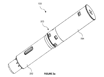
Figure 2a illustrates a perspective view of the auto-injector device,
according to an
embodiment of the present disclosure. Figure 2b illustrates an exploded view
of the auto-
injector device 100, according to an embodiment of the present disclosure.
Figures 3a and
3b illustrate sectional views of the auto-injector device 100, according to an
embodiment of
the present disclosure. Referring to Figure 2a, Figure 2b, and Figure 3a, in
an embodiment,
5
CA 03175677 2022- 10- 14
WO 2021/229606
PCT/IN2021/050463
the auto-injector device 100 may include a first body member 202 and a second
body member
204. The first body member 202 and the second body member 204 may be adapted
to be
coupled to each other in order to define a housing 205 for accommodating
various sub-
components of the auto-injector device 100. In an embodiment, the first body
member 202
and the second body member 204 may be coupled with each other through snap
locks, without
departing from the scope of the present disclosure.
Further, the auto-injector device 100 may include a syringe assembly 206, a
Pre-filled
Syringe (PFS) holder 208, a needle guard 210, a needle guard spring 212, a
locking member
214, a plunger 216, a plunger spring 218, and spring release arms 220. In an
embodiment. the
syringe assembly 206 may include, but is not limited to, a needle 222 and a
barrel 224 adapted
to be coupled to the needle 222. The barrel 224 may be adapted to hold the
medicaments. The
barrel 224 may include a front portion and a rear portion distal to the front
portion. The front
portion may be adapted to be coupled to the needle 222 and the rear portion
may be adapted
to movably receive the plunger 216.
Further, the needle 222 may be adapted to expel medicaments from the syringe
assembly 206. The needle 222 may be adapted to be coupled to the front portion
of the barrel
224 such that a flow of the medicaments may be directed out of the barrel 224
through the
needle 222 during an operation of the auto-injector device 100. Further, the
PFS holder 208
may be adapted to hold the syringe assembly 206 within the housing 205 of the
auto-injector
device 100.
In an embodiment, the needle guard 210 may be adapted to accommodate the PFS
holder 208 along with the syringe assembly 206 in the auto-injector device
100. The needle
guard 210 may include a proximal end 210-1 and a distal end 210-2. Further,
the needle guard
spring 212 may be adapted to be coupled to the needle guard 210. The needle
guard spring
212 may be provided to allow a resilient movement of the needle guard 210 in a
direction
along an axis X-X' of the auto-injector device 100 during the operation of the
auto-injector
device 100.
Further, the spring release arms 220 may be positioned at the proximal end 102
of the
auto-injector device 100. In an embodiment, the spring release arm 220 may he
adapted to be
coupled to the second body member 204. The spring release arms 220 may be
adapted to
support the plunger 216 and the plunger spring 218 within the auto-injector
device 100. The
plunger 216 may be positioned coaxially with respect to the barrel 224. The
plunger 216 may
be adapted to reciprocate within the barrel 224 to expel the medicaments and
to draw the
medicaments in the barrel 224. The plunger 216 may be adapted to be moved
along the axis
6
CA 03175677 2022- 10- 14
WO 2021/229606
PCT/IN2021/050463
X-X' of the auto-injector device 100. The plunger 216 may be adapted to
reciprocate within
the barrel 224 of the syringe assembly 206 for expelling the medicaments from
the syringe
assembly 206 and for drawing the medicaments within the barrel 224.
Further, the plunger spring 218 may be provided to allow resilient movement of
the
plunger 216 within the barrel 224 in the direction along the axis X-X' . In
particular, during
the operation of the auto-injector device 100, the plunger spring 218 may be
adapted to
resiliently push the plunger 216 within the barrel 224 in order to expel the
medicaments from
the barrel 224 of the syringe assembly 206. The plunger spring 218 may be
adapted to be
compressed between a head portion of the plunger 216 and the locking member
214.
Figure 4 illustrates a perspective view of the plunger 216 of the auto-
injector device
100, according to an embodiment of the present disclosure. In an embodiment,
the locking
member 214 may be adapted to be engaged with the plunger 216 to hold the
plunger in a
position with respect to the barrel 224. Further, the locking member 214 may
be adapted to
hold the spring release arm 220 in a locking position to ensure engagement of
the spring
release arm 220 with the plunger 216. In an embodiment, the locking member 214
may be
adapted to circumscribe at least a portion of the spring release arm 220 to
eliminate flexing of
the spring release arm 220 in a radially outward direction with respect to the
plunger 216 and
thereby, ensuring engagement of the spring release arm 220 with the plunger
216.
Referring to Figure 3a, Figure 3b, and Figure 4, the plunger 216 may include
an
engaging portion 402 extending along a length L of the plunger 216. In an
embodiment, the
engaging portion 402 may be embodied as one of spiral grooves and circular
grooves, without
departing from the scope of the present disclosure. The locking member 214 may
be adapted
to be engaged with the engaging portion 402 of the plunger 216 to hold the
plunger 216 in the
position within the auto-injector device 100. In particular, the locking
member 214 may
engage at one of the plurality of positions in the engaging portion 402 along
the length L of
the plunger 216.
The position of the plunger 216 with respect to the barrel 224 may be adapted
to be
adjusted to vary a volume of medicaments to be expelled from the barrel 224.
The position of
the plunger 216 may be adjusted by engaging the locking member 214 with the
plunger 216
at one of a plurality of positions along the length L of the plunger 216. In
an embodiment, the
locking member 214 may include locking teeth 302 adapted to be engaged with
the engaging
portion 402 of the plunger 216. The locking member 214 may be operable between
an engaged
position and a disengaged position.
7
CA 03175677 2022- 10- 14
WO 2021/229606
PCT/IN2021/050463
In an embodiment, the needle guard 210 may be adapted to move the locking
member
214 from the engaged position to the disengaged position. In the engaged
position, the locking
teeth 302 may be engaged with the engaging portion 402 to hold the plunger 216
in a position
away from the distal end 104 of the auto-injector device 100. In such a
position, the plunger
spring 218 may be compressed between the head portion of the plunger 216 and
the locking
member 214. Further, in the disengaged position, the needle guard 210 may move
the locking
member 214 towards the proximal end 102 of the auto-injector device 100. Owing
to such
movement of the locking member 214, the locking teeth 302 may be disengaged
from the
engaging portion 402 of the plunger 216. Subsequently, the plunger spring 218
may push the
plunger 216 towards the distal end 104 of the auto-injector device 100 within
the barrel 224
to expel the medicaments from the syringe assembly 206.
As mentioned earlier, the position of the plunger 216 with respect to the
barrel 224
within the auto-injector device 100 may be adjustable for delivering different
volumes of
medicaments from the auto-injector device 100. Referring to Figure 3b and
Figure 4, in one
instance, the locking member 214 may be engaged with the engaging portion 402
at a distance
X1 with respect to the length L of the plunger 216. In such an instance, the
plunger 216 may
be held at a position P1 with respect to the front portion 210-1 of the barrel
224 within the
auto-injector device 100.
Owing to such a position of the plunger 216, the barrel 224 may hold a volume
V1, i.e.,
a maximum volume, of medicaments for dispensing through the needle 222 during
the
operation of the auto-injector device 100. In another instance, the locking
member 214 may
be engaged with the engaging portion 402 at a distance X2 with respect to the
length L of the
plunger 216. In such an instance, the plunger 216 may be held at a position P2
with respect to
the front portion 210-1 of the barrel 224 within the auto-injector device 100.
Owing to such a
position of the plunger 216, the barrel 224 may hold a volume V2 of
medicaments for
dispensing through the needle 222.
Although, in the illustrated embodiment, operation of the plunger 216 and the
locking
member 214 is explained with respect to the positions P1 and P2 of the plunger
216 within
the auto-injector device 100. As would he appreciated by the person skilled in
the art, the
plunger 216 can be locked at a plurality of positions by the locking member
214 for varying
the volume of the medicaments to be delivered from the auto-injector device
100 as per the
requirement, without departing from the scope of the present disclosure.
Figures 5a-5c illustrate operation of the auto-injector device 100 for
delivering
medicaments, according to an embodiment of the present disclosure. Figure 6
illustrates an
8
CA 03175677 2022- 10- 14
WO 2021/229606
PCT/IN2021/050463
enlarged sectional view of a portion A of the auto-injector device 100 as
shown in Figure 5c,
according to an embodiment of the present disclosure. Firstly, in order to
deliver the
medicaments to the sub-Q region of the patient through the auto-injector
device 100, the cap
106 may be removed from the distal end 104 of the auto-injector device 100 to
expose the
needle 222 of the syringe assembly 206.
Further, referring to Figure 5b, the distal end 104 of auto-injector device
100 may be
placed on the site of injection i.e., like skin, corresponding to the sub-Q
region of the patient.
In an embodiment, the site of injection may be selected based on various
parameters, such as
a medical prescription, type of medication, and volume of medicament to be
injected, without
departing from the scope of the present disclosure. Subsequently, the auto-
injector device 100
may be pressed against the skin such that the needle guard 210 is pressed
against the skin
which results in movement of the needle guard 210 in a direction towards the
proximal end
102 of the auto-injector device 100. Owing to such movement of the needle
guard 210, the
needle 222 may be inserted in the sub-Q region of the patient for delivering
the medicaments.
Further, upon injecting the medicaments, the auto-injector device 100 may be
moved away
from the skin which results in the movement of the needle guard 210 to cover
the needle 222
of the auto-injector device 100. This substantially eliminates probable
injuries which might
cause due to exposed needle while withdrawing the auto-injector device 100
from the
injection site.
Referring to Figure 5c and Figure 6, the movement of the needle guard 210 may
push
the locking member 214 towards the proximal end 102 of the auto-injector
device 100. Such
movement of the locking member 214 may result in disengagement of the locking
teeth 302
with the engaging portion 402 of the plunger 216. In particular, the locking
teeth 302 may
move in a lateral direction away from the engaging portion 402 and thereby,
unlocking a
movement of the plunger 216 under a resilient force of the plunger spring 218.
Subsequently,
the plunger 216 may move towards the distal end 104 of the auto-injector
device 100 within
the barrel 224 under the resilient force of the plunger spring 218. The
plunger 216 may push
the medicament held within the barrel 224 for delivering the medicament to the
sub-Q region
of the patient through the needle 222 of the syringe assembly 206. In an
embodiment, a rubber
stopper (not shown) may be attached to the plunger 216 and adapted to be moved
along with
the plunger 216 within the barrel 224 to expel the drug held within the barrel
224 of the syringe
assembly 206. The rubber stopper may be adapted to be inserted in the barrel
224 in a manner
that the rubber stopper may act as a sealing member to prevent egress of the
drug from one
end of the barrel 224. The rubber stopper may be moved along with the plunger
216 to expel
9
CA 03175677 2022- 10- 14
WO 2021/229606
PCT/IN2021/050463
the drug from the barrel 224 through the needle 222 positioned at another end
of the barrel
224.
As would be gathered, the auto-injector device 100 of the present disclosure
includes
the locking member 214 adapted to lock the plunger 216 at different positions
in order to
administer different volumes of medicaments through the auto-injector device
100. The
plunger 216 may include the engaging portion 402 extending along the length L
of the plunger
216. The locking member 214 may be engaged with the engaging portion 402 to
hold the
plunger 216 in a pre-loaded position for expelling the medicaments from the
syringe assembly
206. The locking member 214 can be engaged with the engaging portion 402 at
different
positions along the length L of the plunger 216 in order to vary the volume of
medicament to
be administered through the auto-injector device 100.
Therefore, the auto-injector device 100 can be re-used for different types and
doses of
medicaments without incorporating any alteration to the sub-components of the
auto-injector
device 100. In particular, this may eliminate the requirement for
manufacturing different sub-
components of the auto-injector device 100 for administering different types
and doses of
medicaments. Further, this substantially eliminates the overall manufacturing
cost of the auto-
injector device 100. Therefore, the auto-injector device 100 of the present
disclosure is
flexible in implementation, compact, cost-effective, convenient, and has a
wide range of
applications.
The auto-injector device 100 described herein may be used for delivering
different
therapeutic compounds such as drugs and biologics, including but not limited
to, antibodies,
antisense, RNA interference, gene therapy, primary and embryonic stem cells,
vaccines, and
combinations thereof. For instance, the embodiments described herein may be
utilized in
combination with known monoclonal antibodies including but not limited to
Abciximab,
Abituzumab, Abrilumab, Actoxumab, Adalimumab, Adecatumumab, Aducanumab,
Afasevikumab, Afelimomab, Afutuzumab, Alacizumab pegol, ALD518, ALD403,
Alemtuzumab, Alirocumab, Altumomab pentetate, Amatuximab, AMG 334, Anatumomab
mafenatox, Anetumab ravtansine, Anifrolumab, Anrukinzumab, Apolizumab,
Arcitumomab,
A seri nvacumab, A seli zumab, Atezol zumab, Ati num* Atl zurn ab, Atorol i mu
m ab,
A v elumab, B apineuzumab, B asiliximab, Bavituximab, B ec tumomab, B
egelomab,
Belimumab, Benralizumab, Bertilimumab, Besilesomab, Bevacizumab, Bezlotoxumab,
Biciromab, B imagrumab, Bimekizumab, Bivatuzumab mertan sine, Bleselumab,
Blinatumomab, Blontuvetmab, Blosozumab, Bococizumab, Brazikumab, Brentuximab
vedotin. Briakinumab, Brodalumab, Brolucizumab, Brontictuzumab, B uro sumab,
CA 03175677 2022- 10- 14
WO 2021/229606
PCT/IN2021/050463
Cabiralizumab, Canakinumab, Cantuzumab mertansine, Cantuzumab ravtansine,
Caplacizumab, Capromab pendetide, Casirivimab, Carlumab, Carotuximab,
Catumaxomab,
cBR96-doxorubicin immunoconjugate, Cedelizumab, Cergutuzumab amunaleukin,
Certolizumab pegol, Cetuximab, Citatuzumab bogatox, Cixutumumab, Clazakizumab,
Clenoliximab, Clivatuzumab tetraxetan, Codrituzumab, Coltuximab ravtansine,
Conatumumab, Concizumab, CR6261, Crenezumab, Crotedumab, Dacetuzumab,
Daclizumab, Dalotuzumab, Dapirolizumab pcgol, Daratumumab, Dectrckumab,
Dcmcizumab, Denintuzumab mafodotin, Deno sumab, Dcpatuxizumab mafodotin,
Derlotuximab biotin, Detumomab, Dinutuximab, Diridavumab, Domagrozumab,
Dorlimomab aritox, Drozitumab, Duligotumab, Dupilumab, Durvalumab,
Dusigitumab,
Ecromeximab, Eculizumab, Edobacomab, Edrecolomab, Efalizumab, Efungumab,
Eldelumab, Elgemtumab, Elotuzumab, Elsilimomab, Emactuzumab, Emibetuzumab,
Emicizumab, Enavatuzumab, Enfortumab vedotin, Enlimomab pegol, Enoblituzumab,
Enokizumab, Enoticumab, Ensituximab, Epitumomab cituxetan, Epratuzumab,
Erenumab,
Erlizumab, Ertumaxomab, Etaracizumab, Etrolizumab, Evinacumab, Evolocumab,
Exbivirumab, Fanolesomab, Faralimomab. Farletuzumab, Fasinumab, FBTA05,
Felvizumab,
Fezakinumab, Fibatuzumab, Ficlatuzumab, Figitumumab, Firivumab, Flanvotumab,
Fletikumab, Fontolizumab, Foralumab, Foravirumab, Fresolimumab, Fulranumab,
Futuximab, Galcanezumab, Galiximab, Ganitumab, Gantenerumab, Gavilimomab,
Gemtuzumab ozogamicin, Gevokizumab, Girentuximab, Glembatumumab vedotin,
Golimumab, Gomiliximab, Guselkumab, Ibalizumab, Ibritumomab tiuxetan,
Icrucumab,
Idarucizumab, Igovomab, IMA-638, IMAB362, Imalumab, Imciromab, Imdevimab,
Imgatuzumab, Inclacumab, Indatuximab ravtansinc, Indusatumab vcdotin,
Incbilizumab,
Inolimomab, lnotuzumab ozogamic in, Intetumumab, 1pilimumab, Iratumumab,
Isatuximab, Itolizumab, Ixekizumab, Keliximab, Labetuzumab, Lambrolizumab,
Lamp al i zum ab, Lan adelum ab, Landogrozumab, Laprituximab emtan sine, LB R -
101/PF0442g7429, Lebrikizumab, Lemalesomab, Lendalizumab, Lenzilumab,
Lerdelirnumab, Lexatumumab, Libivirumab, Lifastuzumab vedotin, Ligelizumab,
Lilotomab
satetraxetan, Li ntuzumab, Lirilumab, Lodelci zumab, Lokivetmab, Lorvotuzumab
mertansine,
Lucatumumab. Lulizumab pegol, Lumiliximab, Lumretuzumab, LY2951742,
Mapatumumab, Margetuximab, Maslimomab, Matuzumab, Mavrilimumab, Mepolizumab,
Metelimumab, Milatuzumab, Minretumomab. Mirvetuximab soravtansine, Mitumomab,
Mogamulizumab, Monalizumab, Morolimumab, Motavizumab, Moxetumomab pasudotox,
Muromonab-CD3, Nacolomab tafenatox, Nam ilumab, Naptumomab estafenatox,
11
CA 03175677 2022- 10- 14
WO 2021/229606
PCT/IN2021/050463
Naratuximab emtansine, Narnatumab, Natalizumab, Navicixizumab, Navivumab,
Nebacumab, Necitumumab, Nemolizumab, Nerelimomab, Nesvacumab, Nimotuzumab,
Nivolumab, Nofetumomab merpentan, Obiltoxaximab, Obinutuzumab, Ocaratuzumab,
Ocrelizumab, Odulimomab, Ofatumumab, Olaratumab, Olokizumab, Omalizumab,
Onartuzumab, Ontuxizumab, Opicinumab, Oportuzumab monatox. Oregovomab,
Orticumab,
Otelixizumab, Otlertuzumab, Oxelumab, Ozanezumab, Ozoralizumab, Pagibaximab,
Palivizumab, Pamrcvlumab, Panitumumab, Pankomab, Panobacumab, Parsatuzumab,
Pascolizumab, Pasotuxizumab, Patcclizumab, Patritumab, Pembrolizumab,
Pemtumomab,
Perakizumab, Pertuzumab, Pexelizumab, Pidilizumab, Pinatuzumab vedotin,
Pintumomab,
Placulumab, Plozalizumab, Pogalizumab, Polatuzumab vedotin, Ponezumab,
Prezalizumab,
Priliximab, Pritoxaximab, Pritumumab, PRO 140, Quilizumab, Racotumomab,
Radretumab,
Rafivirumab, Ralpancizumab, Ramucirumab, Ranibizumab, Raxibacumab,
Refanezumab,
Regavirumab, Reslizumab, Rilotumumab, Rinucumab, Risankizumab, Rituximab,
Rivabazumab pegol, Robatumumab, Roledumab, Romosozumab, Rontalizumab,
Rovalpituzumab tesirine, Rovelizumab, Ruplizumab, Sacituzumab govitecan,
Samalizumab,
Sapelizumab, Sarilumab, Satumomab pendetide, Secukinumab, Seribantumab,
Setoxaximab,
Sevirumab, SGN-CD19A, SGN-CD33A, Sibrotuzumab, Sifalimumab, Siltuximab,
Simtuzumab, Siplizumab, Sirukumab, Sofituzumab vedotin, Solanezumab,
Solitomab,
Sonepcizumab, Sontuzumab, Stamulumab, Sulesomab, Suvizumab, Tabalumab,
Tacatuzumab tetraxetan, Tadocizumab, Talizumab, Tamtuvetmab, Tanezumab,
Taplitumomab paptox, Tarextumab, Tefibazumab, Telimomab aritox, Tenatumomab,
Teneliximab, Teplizumab, Teprotumumab, Tesidolumab, Tetulomab, Tezepelumab,
TGN1412, Ticilimumab, Tigatuzumab, Tildrakizumab, Timolumab, Tisotumab
vedotin,
TN X- 650, To cilizumab, Toralizumab, To s atoxumab, To s itumomab ,
Tovetumab,
Tralokinumab, Trastuzumab, Trastuzumab emtansine, TRB S07, Tregalizumab,
Tremelimumab, Trevogrumab, Tucotuzumab celmoleukin, Tuvirumab, Ublituximab,
Ulocuplumab, Urelumab, Urtoxazumab, Ustekinumab, Utomilumab, Vadastuximab
talirine,
Vandortuzumab vedotin, Vantictumab, Vanucizumab, Vapaliximab, Varlilumab,
Vatel izu mab, Vedol zu mab, Veltuzu mab, Vepal i mo mab, Vesencu mab, Vi s
ilizu m ab,
Vobarilizumab, Volociximab, Vorsetuzumab mafodo tin, Votumumab, Xentuzumab,
Zalutumumab, Zanolimumab, Zatuximab, Ziralimumab, and Zolimomab aritox or
combinations thereof.
12
CA 03175677 2022- 10- 14
WO 2021/229606
PCT/IN2021/050463
While specific language has been used to describe the present subject matter,
any
limitations arising on account thereto, are not intended. As would be apparent
to a person in
the art, various working modifications may be made to the method in order to
implement the
inventive concept as taught herein. The drawings and the foregoing description
give examples
of embodiments. Those skilled in the art will appreciate that one or more of
the described
elements may well be combined into a single functional element. Alternatively,
certain
elements may be split into multiple functional elements. Elements from one
embodiment may
be added to another embodiment.
13
CA 03175677 2022- 10- 14