Note: Descriptions are shown in the official language in which they were submitted.
CA 03175942 2022-09-19
WO 2021/188964
PCT/US2021/023259
CURRENT SENSING IN A WIRELESS POWER TRANSFER SYSTEM
TECHNICAL FIELD
[0001] This disclosure relates to current measurement and, more particularly,
to current
measurement in a wireless power transfer system.
BACKGROUND
[0002] Resonant induction wireless charging makes use of an air core
transformer consisting of
two concentric coils displaced along a common coil axis. Electrical power is
sent from the
sending apparatus (i.e. the primary coil) to the receiving apparatus (i.e. the
secondary coil) by
means of magnetic flux linkage between the two transfer coils. An alternating
current flowing in
the primary coil induces an alternating current into the secondary coil.
[0003] One option for constructing coils is use of Litzendraht (aka Litz) wire
or other
conductive filaments. Litz wire consists of individually insulated wires
twisted or braided into a
uniform pattern with the primary benefit of reducing AC losses in high
frequency windings.
Alternately, as described in PCT Patent Application US2018035060, "WIRELESS
POWER
TRANSFER THIN PROFILE COIL ASSEMBLY," the coil conductors can be comprised of
multiple conductive traces layered into an insulative, dielectric substrate
(e.g. a printed circuit
board).
[0004] An electric current is defined as an electric charge (e.g. electrons)
in motion. Current is
dq/dt, or the time rate of change of charge. The measure of flow of the
current of electricity is
expressed in amperes. The unit ampere (A) is defined as equal to a flow of one
coulomb of charge
per second. Measurement of current in an electrical circuit may be
accomplished directly (e.g.
using a sense resistor) or indirectly (e.g. using a Hall-effect sensor or an
inductive sensor).
[0005] It is desired to provide a current measurement device for the high
currents that may exist
in wireless power transfer systems without adversely affecting the operation
of the wireless power
transfer system.
SUMMARY
.. [0006] Various details for the embodiments of the inventive subject matter
are provided in the
accompanying drawings and in the detailed description text below.
[0007] In sample embodiments, a current sensing device is provided for
measuring current
through a coil having a plurality of coil windings (e.g., Litz wire, printed
circuit board traces, or
conductive filaments). The coil windings are impedance matched and tightly
coupled via mutual
inductance with each other. The current sensing device includes a current
sensing resistor
connected to a subset of the plurality of coil windings to measure current
through the subset of the
plurality of coil windings, a voltage sensor that measures a voltage drop
across the current sensing
- 1 -
CA 03175942 2022-09-19
WO 2021/188964
PCT/US2021/023259
resistor, and a processor that determines a fractional current and phase of
the coil from the measured
current and voltage. In sample embodiments, the coil is a secondary winding
used in a wireless
power transfer system (inductive system or capacitively coupled system)
including a rectifier that
converts an alternating current on the secondary winding into a direct current
for application to a
load. An analog to digital converter may also be provided to digitize the
voltage measured by the
voltage sensor and to provide the measured voltage to the processor.
[0008] In sample applications, the processor determines a total current I
through the secondary
winding as I = nV/sqrt(2R + 27E * L * f), where n is a number of coil windings
of the secondary
winding, V is the measured voltage, R is a resistance of the current sensing
resistor, L is an
inductance of the secondary winding, and f is a frequency of the alternating
current on the secondary
winding. Alternatively, the processor may determine a total current I through
the secondary
winding as I = fIRVn/Rn/n)11*m, where Vn is the measured voltage for each
secondary winding,
Rn is a resistance for each current sensing resistor of each secondary
winding, n is a number of coil
windings sampled, and m is a total number of coil windings of the coil. The
processor determines
the fractional current and phase of the coil by calculating a total current of
the coil as I = n(V/Rz),
where n is a number of coil windings of the coil, V is the measured voltage,
and Rz is an impedance
of the current sensing resistor.
[0009] In sample embodiments, the sensing resistor has a value R>>X, where X =
27i * L * f,
where L is an inductance of the secondary winding, and f is a frequency of the
alternating current
on the secondary winding. For example, R> riX, where n is a number of coil
windings of the coil.
[0010] A method of measuring current through a coil comprising a plurality of
coil windings is
also provided. The method includes using a current sensing resistor to measure
a current through a
subset of the plurality of coil windings, measuring a voltage drop across the
current sensing resistor,
and determining a fractional current and phase of the coil from the measured
current and voltage.
The method may be implemented in embodiments where the coil is a secondary
winding used in a
wireless power transfer system comprising a rectifier that converts an
alternating current on the
secondary winding into a direct current for application to a load. The method
further includes
digitizing the measured voltage and providing the measured voltage to a
rectifier controller that
determines the fractional current and phase of the coil and controls the
operation of the rectifier.
[0011] In sample embodiments of the method, the method includes calculating a
total current I
through the secondary winding as I = nV/sqrt(2R + 27t * L * f), where n is the
number of coil
windings of the secondary winding, V is the measured voltage, R is a
resistance of the current
sensing resistor, L is an inductance of the secondary winding, and f is a
frequency of the alternating
current on the secondary winding. The method may further include calculating a
total current I
through the secondary winding as I = IEKVn/Rn/n)11*m, where Vn is a measured
voltage for each
sampled secondary winding, Rn is a resistance for each current sensing
resistor of each sampled
secondary winding, n is a number of coil windings sampled, and m is a total
number of coil windings
- 2 -
CA 03175942 2022-09-19
WO 2021/188964
PCT/US2021/023259
of the coil. The method may also include calculating a total current of the
coil as I = n(V/Rz), where
n is the number of coil windings of the coil, V is the measured voltage, and
Rz is an impedance of
the current sensing resistor.
[0012] The method may further include selecting the current sensing resistor
to (a) limit
inductance to prevent out-of-phase subtraction when measured current returns
to the plurality of
coil windings and/or (b) reduce impact of inductance while keeping heating and
power loss to a
minimum. In sample embodiments, the current sensing resistor is selected to
have a value R>>X,
where X = 27E * L * f, where L is an inductance of the secondary winding, and
f is a frequency of
the alternating current on the secondary winding. For example, R may be
selected such that R>
nX, where n is a number of coil windings of the coil.
[0013] This summary section is provided to introduce aspects of the inventive
subject matter in
a simplified form, with further explanation of the inventive subject matter
following in the text of
the detailed description. This summary section is not intended to identify
essential or required
features of the claimed subject matter, and the particular combination and
order of elements listed
this summary section is not intended to provide limitation to the elements of
the claimed subject
matter. Rather, it will be understood that the following section provides
summarized examples of
some of the embodiments described in the Detailed Description below.
BRIEF DESCRIPTION OF THE DRAWINGS
[0014] The foregoing and other beneficial features and advantages of the
invention will become
apparent from the following detailed description in connection with the
attached figures, of
which:
[0015] FIG. 1 schematically illustrates current measurement in a wireless
power transmission
system in a sample embodiment.
[0016] FIG. 2 functionally illustrates a wireless power transfer system that
uses current
measurements in a sample embodiment.
[0017] FIG. 3 illustrates current measurement hardware in a sample embodiment.
DETAILED DESCRIPTION OF ILLUSTRATIVE EMBODIMENTS
[0018] The current sensing for wireless power transmission and associated
method described
herein may be understood more readily by reference to the following detailed
description taken in
connection with the accompanying figures and examples, which form a part of
this disclosure. It
is to be understood that this description is not limited to the specific
products, methods, conditions
or parameters described and/or shown herein, and that the terminology used
herein is for the
purpose of describing particular embodiments by way of example only and is not
intended to be
limiting of any claimed subject matter. Similarly, any description as to a
possible mechanism or
mode of action or reason for improvement is meant to be illustrative only, and
the subject matter
- 3 -
CA 03175942 2022-09-19
WO 2021/188964
PCT/US2021/023259
described herein is not to be constrained by the correctness or incorrectness
of any such suggested
mechanism or mode of action or reason for improvement. Throughout this text,
it is recognized
that the descriptions refer both to methods and systems/software for
implementing such methods.
[0019] A detailed description of illustrative embodiments will now be
described with reference
to FIGS. 1-3. Although this description provides a detailed example of
possible implementations,
it should be noted that these details are intended to be exemplary and in no
way delimit the scope
of the inventive subject matter.
[0020] Indirect current sensing is typically used in circuits with load
currents in the 100A-
1000A range. Indirect current sensing allows galvanic isolation from the
conductor under
measurement. When using a Hall effect-based sensor, the sensor is installed
between the anode
and load. The Hall effect sensor uses the Lorentz force (the force exerted on
an electron moving
through a magnetic field) which creates a voltage difference (the Hall
voltage) across an electrical
conductor, transverse to the current in the conductor and to an applied
magnetic field
perpendicular to the current to determine alternating current (AC) and direct
current (DC) flow.
The inductive current sensor or current sense transformer uses Faraday's law
of induction with the
conducting wire acting as primary and the voltage output as secondary to
measure alternating
current (AC) in the conducting wire based on the magnetic flux produced.
[0021] Since at high power with a high impedance load, the wireless power
transfer (WPT)
system will always be a current source (i.e., a AC Voltage Controlled Current
Source) and since
high power WPT systems will generate stray magnetic flux, use of the indirect
measurement
techniques and technologies are problematic especially as part of the closed
control loop of an
active rectifier.
[0022] A direct method of current measurement is through use of a sense
resistor. The sense
resistor, nominally a resistor with a small Ohmic value, is placed in-line
with a circuit network,
typically close to the circuit ground or battery cathode. The total current
through the sense
resistor is then measured by measuring the voltage drop across the resistor
and computing current
as i(t)=v(t)/R where i(t) is the current, in amperes, as a function of time,
v(t) is the voltage across
the sense resistor, in volts, as a function of time, and R is the resistance
of the sense resistor, in
Ohms. The sense resistor is selected to have a minimal resistance to avoid
excessive heating and
perturbation of the power delivery to the load (because power loss in the
sense resistor is
proportional to the resistance).
[0023] For alternating current systems, such as the for use in a magnetic
resonance-based WPT
system, the sense resistor selected should have a minimal reactance component
of the total
impedance for the same reasons. The requirement for a precise AC signal
measurement (e.g.
current, frequency, phase), at the frequency of concern, drives the
requirement for a reactance that
must be small relative to the resistance.
- 4 -
CA 03175942 2022-09-19
WO 2021/188964
PCT/US2021/023259
[0024] The use of a current sense resistor in a high current system (e.g., 125
Amps RMS and
higher) to measure the full AC current is prohibitive due to power dissipation
heating. Another
issue is the physics of construction of a resistor physically large enough to
handle that current
without creating a large unavoidable inductance. The additional parasitic
inductance may then
add too much phase angle to the AC signal for an accurate measurement.
[0025] However, a fractional current sensing method can be constructed for a
WPT system that
exploits the multi-conductor construction of the secondary's coil windings to
separate a subset of
the conductors which are then connected through a resistor with a low Ohm
rating. The
conductor current passes through the very small value resistor (with the
inherent parasitic
inductance) and the voltage drop is measured across the resistor to determine
the fractional
current and phase.
[0026] A current sensing resistor is low cost and remains reliable even in the
presence of stray
magnetic flux generated by the WPT system. However, because the current sense
resistor is a
resistive element (albeit one with some self-inductance), the heat it
generates is proportional to the
square of current passing therethrough, limiting its usefulness in a high
current power supply like
that used in a WPT system. However, by exploiting the multi-element
construction of a magnetic
coil, a sense resistor placed on a single conductor can produce a measurement
of the fractional
current without generating excessive heat, while also not impinging on the
power delivery
capabilities of the system as a whole. This fractional current measurement
provides accurate
phase measurement with multiplication and accurate current measurement for the
control system
(e.g., the active rectification system and power control feedback).
[0027] In practice, any resistor includes an inevitable parasitic inductance.
This inductance
leads to a phase shift in the output. Since the measured conductor is returned
to the bundle of
tightly coupled parallel conductors, and thru mutual inductance shares the
total current load, the
power reduction may be far more than that of the just resistive heating loss.
[0028] Since resistor construction varies, a low inductance model can be
selected. Since the
impact of the resistor on delivered power (and dissipative heating) is reduced
by the fraction of
conductors sensed over the total number of conductors, in the fractional
current measurement
system, a larger Ohm (relatively) resistor can be selected to reduce the
relative impact of the self-
inductance component. The larger resistor value also creates a greater dynamic
voltage range for
more precise voltage and thus fractional current level and current phase
sensing.
[0029] In sample embodiments, the sensing resistor is selected to limit
inductance or to use a
high but still relatively low value to reduce impact of the inductor while
keeping heating and
power loss to a minimum. A higher resistance provides a higher dynamic range
for voltage
leading to more accurate current sensing. The inductance is also limited to
prevent out-of-phase
subtraction when measured current returns to the tightly coupled bundle of
conductors.
- 5 -
CA 03175942 2022-09-19
WO 2021/188964
PCT/US2021/023259
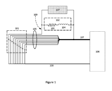
FIGURE 1
[0030] In FIG. 1, multiple conductors (e.g., Litz wire, printed circuit board
traces, or
conductive filaments) are used in the secondary coil of a WPT system (e.g. an
inductive system, a
magnetic resonant coupled inductive system, or even a capacitively coupled
system). The
secondary 101 appears in the circuit as a bank of independent current supplies
each with its own
conductor 105. Each conductor 105 is impedance matched and tightly coupled,
via mutual
inductance, with the other conductors 105. FIG. 1 uses ten conductors 105 for
purposes of
illustration only. The load 106 is supplied with power from the secondary 101
via a power bus
107 that combines the individual conductors 105 into a single conductor or
power bus. The
circuit is completed by the return electrical bus 108 from the load 106 to the
secondary 101.
[0031] Current measurement is achieved by selection of a subset of the
independent conductors
105 (in this example a single conductor 109) which connect via a current sense
resistor 102. The
current sense resistor 102 has both a resistive impedance component (the
reactance) 103 as well as
an inductive impedance component 104. The voltage sensor 107 reads the voltage
drop across the
current sense resistor 102.
[0032] The voltage sensor readings 107 and the impedance of the resistor 102
are used to derive
current. Since the impedance matched, tightly coupled conductors 105 share
current produced by
the secondary 101, the total current delivered to the load 106 can be
calculated. For example,
when a single conductor 109 is measured, the total current is n(V/Rz) where n
is the number of
conductors (e.g. n=1 for single conductor), V is the measured voltage across
the sense resistor
102, and Rz is the impedance of the sense resistor 102.
FIGURE 2
[0033] In FIG. 2, a high-level schematic for a direct current battery charging
circuit using
magnetic induction with current measurement in a sample embodiment is shown.
The receiver
201 or secondary consists of a secondary coil with multiple windings 202. The
receiver 201 can
be inductive, resonant inductive or capacitive. The receiver 201 converts the
magnetic field from
the transmitter (not shown) into an alternating electrical current. The
alternating current 208
developed by the resonant network 201 is used to power the load 203. The first
stage of the load
is a passive (diode-based) or active (switch-based) rectifier 204 that can be
used to convert the
alternating current to the direct current needed to charge the battery 206 (a
battery may be wet,
dry, solid state, capacitive or hybrid (e.g. a battery with capacitive
component)). For charging a
battery 206, the rectified DC signal may be smoothed and level-converted by
the conditioner
circuitry 205.
- 6 -
CA 03175942 2022-09-19
WO 2021/188964
PCT/US2021/023259
[0034] The current sensor 209 is used to monitor the alternating current 208
developed by the
receiver 201. The current level, frequency, and phase is reported to the
controller 207. The
controller 207 may report electrical signal characteristics to ancillary
systems such as displays,
closed loop control systems, safety systems, and active rectification control
switching.
FIGURE 3
[0035] FIG. 3 shows an example embodiment of a current sensor using a current
sense resistor
301. The current sense resistor 301 has both resistive (ohmic) 302 and
inductive 303 impedance
components. In this example, an Analog-to-Digital Converter (ADC) 304, is used
to digitize the
voltage produced across the current sense resistor 301. The ADC 304 connects
to other systems,
such as an active rectification controller 207, using a digital interface 305.
The active rectification
controller 207 may include a processor that calculates the current from the
measured values as
described herein.
[0036] As an example, for a WPT system with a 60 conductive element receiver
with a single
conductor measured, the current through the measured conductor would be i =
V/sqrt(R2 + 2ic * L
* f), where i is the single conductor current in Amps, V is the measured
voltage in Volts, R2 is the
resistor value in Ohms, and L is the inductor value of the secondary coil in
Henrys, and f is the
frequency of the AC signal in Hertz.
Alternative Embodiment ¨ Multiple Parallel Current Sensing
[0037] Once the single conductor current (i) is calculated, the current is
multiplied by the
number of tightly coupled conductors to determine a system current level. In
other words, the
current would be i = nV/sqrt(R2 + 27( * L * f), where n is the number of
conductors. In cases
where multiple conductors are measured, the sum of individual measured
currents are averaged.
This average per conductor current is then multiplied by the number of tightly
coupled conductors
to determine the total system current level.
[0038] In the simplest case, a single conductor is separated from the tightly
inductively coil
windings for fractional current sensing. In some cases, multiple conductors
can be sensed, each
with its own current sense resistor. In the case of multiple conductors, the
sensed current is
averaged and then multiplied:
i(total) = IEKVn/Rn)/n11* m
where i(total) is the system current, Vn is the sampled voltage in conductors
1 to n, and Rn is the
current resistors impedance for each resistor, where n is the number of
conductors sampled and m
is the total number of conductors.
- 7 -
CA 03175942 2022-09-19
WO 2021/188964
PCT/US2021/023259
Alternative Embodiment ¨ Unknown Parasitic Induction
[0039] For high power (i.e., high current) systems, using a single current
sense resistor to sense
the entire alternating current is not desirable because of the power
dissipation (via heating) in that
resistor. This heating can be mitigated by using an arbitrarily small value
resistor. However,
when the resistance value becomes too small, the impedance of the sense
resistor starts to be
dominated by reactance, i.e. the parasitic inductance of the sense resistor.
This reactance
dominance leads to unwanted phase shifts and also affects the magnitude of the
measurement of
the alternating current as follows:
v(0= i(t)*[sqrt(R + 2it * L * 01
where v(t) is the voltage, i(t) is the current, R is the ohmic value of the
sense resistor, L is the
inductance inherent in the sense resistor, and f is the frequency of the AC
signal.
[0040] Since voltage, v(t), is the quantity that is measured by the
measurement system (see, e.g.,
FIG. 3), it can be seen by inspection that if the quantity under the radical
increases, then the
sensed voltage, v(t) will increase. So, in the case of a sense resistor where
R << X, (where X =
* L * 0, the sensed voltage, from which the current is computed, will be
dominated by the
inductance. If the exact inductance is unknown, then it is nearly impossible
to compute an
accurate current. However, the system and method of fractional current sensing
of tightly coupled
parallel conductors circumvents this problem by allowing R to be >> X.
[0041] For example, if n=60 conductors, when sensing 1/60 of the total current
(a single
conductor of the total), the resistance of the sense resistor can be 60x
greater than the case of
using a single sense resistor to sense to total current. More generally, R>
riX, where n is the
number of coil windings of the coil. This, of course, assumes that the power
dissipation of the
sense resistor is held constant.
[0042] The advantage of the fractional sensing concept is that with R>>X, not
only is the phase
angle very close to zero, but the amplitude of the voltage signal is dominated
by the real
component of the impedance, that is, the ohmic resistance. So practically
speaking, knowing the
exact parasitic inductance of the sense resistor is not necessary for
computing an accurate voltage
measurement (and thus current level, phase and frequency) as long as the
resistance component is
much larger than the reactance created by the inductive component.
CONCLUSION
[0043] While various implementations have been described above, it should be
understood that
they have been presented by way of example only, and not limitation. For
example, any of the
elements associated with the systems and methods described above may employ
any of the
- 8 -
CA 03175942 2022-09-19
WO 2021/188964
PCT/US2021/023259
desired functionality set forth hereinabove. Thus, the breadth and scope of a
preferred
implementation should not be limited by any of the above-described sample
implementations.
[0044] As discussed herein, the logic, commands, or instructions that
implement aspects of the
methods described herein may be provided in a computing system including any
number of form
factors for the computing system such as desktop or notebook personal
computers, mobile devices
such as tablets, netbooks, and smartphones, client terminals and server-hosted
machine instances,
and the like. Another embodiment discussed herein includes the incorporation
of the techniques
discussed herein into other forms, including into other forms of programmed
logic, hardware
configurations, or specialized components or modules, including an apparatus
with respective
means to perform the functions of such techniques. The respective algorithms
used to implement
the functions of such techniques may include a sequence of some or all of the
electronic
operations described herein, or other aspects depicted in the accompanying
drawings and detailed
description below. Such systems and computer-readable media including
instructions for
implementing the methods described herein also constitute sample embodiments.
[0045] The monitoring and control functions of the controller 207 described
herein may be
implemented in software in one embodiment. The software may consist of
computer executable
instructions stored on computer readable media or computer readable storage
device such as one
or more non-transitory memories or other type of hardware-based storage
devices, either local or
networked. Further, such functions correspond to modules, which may be
software, hardware,
firmware, or any combination thereof. Multiple functions may be performed in
one or more
modules as desired, and the embodiments described are merely examples. The
software may be
executed on a digital signal processor, ASIC, microprocessor, or other type of
processor operating
on a computer system, such as a personal computer, server, or other computer
system, turning
such computer system into a specifically programmed machine.
[0046] Examples, as described herein, may include, or may operate on,
processors, logic, or a
number of components, modules, or mechanisms (herein "modules"). Modules are
tangible
entities (e.g., hardware) capable of performing specified operations and may
be configured or
arranged in a certain manner. In an example, circuits may be arranged (e.g.,
internally or with
respect to external entities such as other circuits) in a specified manner as
a module. In an
example, the whole or part of one or more computer systems (e.g., a
standalone, client or server
computer system) or one or more hardware processors may be configured by
firmware or
software (e.g., instructions, an application portion, or an application) as a
module that operates to
perform specified operations. In an example, the software may reside on a
machine readable
medium. The software, when executed by the underlying hardware of the module,
causes the
hardware to perform the specified operations.
[0047] Accordingly, the term "module" is understood to encompass a tangible
hardware and/or
software entity, be that an entity that is physically constructed,
specifically configured (e.g.,
- 9 -
CA 03175942 2022-09-19
WO 2021/188964
PCT/US2021/023259
hardwired), or temporarily (e.g., transitorily) configured (e.g., programmed)
to operate in a
specified manner or to perform part or all of any operation described herein.
Considering
examples in which modules are temporarily configured, each of the modules need
not be
instantiated at any one moment in time. For example, where the modules
comprise a general-
.. purpose hardware processor configured using software, the general-purpose
hardware processor
may be configured as respective different modules at different times. Software
may accordingly
configure a hardware processor, for example, to constitute a particular module
at one instance of
time and to constitute a different module at a different instance of time.
[0048] Those skilled in the art will appreciate that the topology and circuit
implementation
methodology described herein enables effective realization as a single
application specific
integrated circuit. Further, while the disclosure contained herein pertains to
the provision of
electrical power to vehicles, it should be understood that this is only one of
many possible
applications, and other embodiments including non-vehicular applications are
possible. For
example, those skilled in the art will appreciate that there are numerous
applications of providing
.. a current source safety circuit in non-vehicle inductive charging
applications such as portable
consumer electronic device chargers, such as those (e.g., PowerMatTm) used to
charge
toothbrushes, cellular telephones, and other devices. Accordingly, these and
other such
applications are included within the scope of the following claims.
- 10 -