Note: Descriptions are shown in the official language in which they were submitted.
WO 2021/214002
PCT/EP2021/060139
HYBRID PACKAGE AND METHOD ASSOCIATED
The present invention relates generally to packaging and particularly,
although not exclusively,
to a hybrid material package such as ajar, pot, cup, tub or the like.
Use of more than one different type of material can be used to create
packaging with multiple
benefits, including benefits for performance and environmental impact.
The present invention seeks to provide improvements in or relating to
packaging.
An aspect of the present invention provides a package comprising a frame
formed from a
plastics material and a wall formed from a paper or paper-based material.
This aspect therefore allows for the incorporation of paper into packaging.
The frame may be formed from a polyolefin polymer such as polypropylene.
An aspect of the present invention provides a package comprising a frame
formed from a
plastics material and a wall formed from a fibre-based material.
An aspect of the present invention provides a package comprising a frame
formed from a
plastics material and a wall formed from a non-woven material.
An aspect of the present invention provides a hybrid package comprising a wall
formed from a
paper or paper-based material and a frame formed from a plastics material, in
which the frame
includes a step which is positioned against a free edge of the wall, whereby
one or more
exposed edges of the wall are protected by the frame.
In some embodiments all exposed edges of the wall are covered by the frame
i.e. there is
substantially no part of the edge of the wall which is exposed. This could be
particularly useful,
for example, for parts of the wall likely to come into contact with surfaces
(e.g. at or towards the
bottom of a package), where preventing exposed edges coming into direct
contact with a
surface can prevent moisture entry and ingress into the paper material.
In some embodiments a step is provided in the region of a frame corner.
Paper components of a package (e.g. the wall) may be provided as a blank which
is cut,
stamped or otherwise formed from a stock. This could result in exposed edges,
which may be
particularly susceptible to moisture entry.
1
CA 03175972 2022- 10- 18
WO 2021/214002
PCT/EP2021/060139
The wall may, for example, be formed from paperboard or cardboard which may be
lined or
coated with plastic or wax. The paperboard/cardboard may be a laminate, for
example
including one or more layers of plastics material such as polypropylene.
Whilst the major
surfaces of the wall would, for example, be coated, if the wall is cut/stamped
from a
stock/blanket the exposed edges would not have this coating.
The wall may be formed as side sleeve/wrap/wall.
The package may further comprise a base, which may be formed separately from
the wall. The
base may be assembled during or after formation of a frame/wall sub-assembly.
The base may comprise paper or paper-based material and/or plastic material.
In some
embodiments a disc-like paperboard base is provided.
The package may comprise a lid. The lid may comprise paper or paper-based
material and/or
plastics material. In some embodiments the lid is formed from just plastics
material. In some
embodiments the lid is a hybrid material part such as a plastics/paperboard
composite, for
example formed by a sequential moulding process.
The frame (for example a lower ring) may include a foot on which the package
rests in use.
This can be useful during post-forming operations (such as filling) and in
subsequent customer
use to protect a paperboard base. The base is therefore at least slightly
sunken from the
bottom end of the frame so that it is raised from a surface when the package
stands on the
frame.
The foot may include one or more steps/ridges/ribs onto/against which a base
may be received
(for example being dropped in from above or pushed in from below).
In some embodiments a wall is overmoulded (for example injection moulded) onto
a frame.
The frame may be formed using an off-centre injection point e.g. offset from a
generally central
axis of the frame.
The frame may be formed with an upper ring and a lower ring. The rings may be
joined by a
stem.
Part of the frame, for example a lower ring, may include an (e.g. radially)
inwardly extending
part that allows formation using an off-centre injection point.
The upper ring may have a larger diameter than the lower ring. In plan the
rings may be
concentric (i.e. share the same central axis). An axially inclined stem may
join the rings
2
CA 03175972 2022- 10- 18
WO 2021/214002
PCT/EP2021/060139
together. Either or both rings may be substantially circular. Other
shapes/forms of the package
are envisaged, including, for example, generally square, generally oval,
generally elliptical,
generally rectangular.
The wall may be generally frustoconical when assembled onto the frame.
The wall (e.g. sidewall) may be formed as a flat blank that is foldable into a
final form. The
blank may be folded only in a single plane.
A further aspect provides a mixed material package comprising an injection
moulded
polypropylene skeleton and a paperboard sleeve.
A package formed in accordance with the present invention may, for example, be
a cup, pot, tub
or a jar.
A further aspect provides a method of forming a package comprising: providing
a wall formed
from a paper or paper-based material; inserting the wall into a mould; and
injection
overmoulding a frame onto the wall.
The mould may be configured such that when closed it presses onto the wall to
define a
boundary (for example a seal) for subsequent material flow during
overmoulding.
In some embodiments a base is also inserted into the mould. The subsequent
injection of the
frame may join/link the base and wall together.
The material for the frame may be injected using an off-centre gate. The mould
may be
provided with a cavity that will form a projecting/extending limb on the frame
which can serve as
an injection gate.
The method may comprise the step of forming the wall from a stock with a
consequence that
exposed edges are formed, and the step of covering the exposed edges with the
frame
material.
A further aspect of the present invention provides a package comprising a tub
including a tub
frame formed from a plastics material and a tub wall formed from a paper or
paper-based
material, and a lid including a lid frame formed from a plastics material and
a lid wall formed
from a paper or paper-based material.
Some aspects allow for the incorporation of paper into packaging.
The tub and/or lid frame may be formed from a polyolefin polymer such as
polypropylene.
3
CA 03175972 2022- 10- 18
WO 2021/214002
PCT/EP2021/060139
The tub and/or lid wall may, for example, be formed from paperboard or
cardboard which may
be lined or coated with plastic or wax. The paperboard/cardboard may be a
laminate, for
example including one or more layers of plastics material such as
polypropylene.
The tub wall may be formed as side sleeve/wrap/wall.
The package further comprises a tub base, which may be formed separately from
the wall. The
base may be assembled during or after formation of a frame/wall sub-assembly.
The base may comprise paper or paper-based material and/or plastic material.
In some
embodiments a disc-like paperboard base is provided.
In some embodiments the lid is a hybrid material part such as a
plastics/paperboard composite,
for example formed by a sequential moulding process.
The lid may, for example, be formed as a snap on lift
The package may, for example, be two components: a tub and a lid. In other
embodiments a
separate top rim may be provided to create the connection to a lid.
The lid may be formed as two components, either or both of which may be formed
from a
"skeleton" frame and a paper insert.
A lid may be formed with a paper board on a flat surface and then injection
moulded the
connection features to get the connection between tub and the two lids.
The tub may comprise a paperboard wall connected with a polypropylene
skeleton.
At the top of the tub there may be a standing edge for a snap on lid.
An aspect of the present invention provides a package comprising a tub and a
lid, the tub
including a tub frame formed from a plastics material and a tub wall formed
from a paper or
paper-based material, the lid comprises a connecting part and a cap part, the
connecting part
connects to the tub and the cap connects to the connecting part.
The connecting part may include a frame (e.g. formed from plastics material)
and a wall (e.g.
formed from a paper or paper-based material).
The cap may include a frame (e.g. formed from plastics material) and a wall
(e.g. formed from a
paper or paper-based material).
4
CA 03175972 2022- 10- 18
WO 2021/214002
PCT/EP2021/060139
The connecting part may snap fit onto the tub. The cap may snap fit onto the
connecting part.
In some embodiments one or more components are formed using an injection
moulding process
e.g. with a wall inserted into a mould cavity and then plastics material
injected into the cavity to
form a skeleton over/on/against the wall.
The material for a frame may be injected using an off-centre gate. A mould may
be provided
with a cavity that will form a projecting/extending limb on a frame which can
serve as an
injection gate.
The lid of some embodiments may comprise a polypropylene frame and a
paperboard deck.
Packages provides with a lid may further comprises a sub-lid which is attached
or attachable to
the lid. A void may be formed between the lid and the sub-lid. The sub-lid may
be a snap-fit
into/onto the lid. Other forms of engagement, such as screw threads, may be
provided.
In some aspects and embodiments of the present invention only a single
injection inlet point is
used for a frame. In other aspects and embodiments multiple inlets are used.
The present invention also provides a wraparound sidewall blank for a hybrid
package. The
blank is removed (e.g. cut/stamped/punched) from a stock sheet of fibre-based
material. As a
result the orientation of the fibres can be controlled (for example to be all
substantially the
same). It will be appreciated that if the sidewall is formed only by bending
in a single plane, the
uni-directional orientation of the fibres will be maintained in the final
hybrid package. This
means, for example, that the fibres can be oriented to provide a particular
benefit. In some
embodiments the sidewall fibres have a generally axial orientation, meaning
that maximum
stiffness is provided in a top load direction.
In some aspects and embodiments the frame includes first and second parts
(e.g. upper and
lower rings). The parts may be joined only by a single channel/stem; or
multiple stems may be
provided.
Different aspects and embodiments of the invention may be used separately or
together.
Further particular and preferred aspects of the present invention are set out
in the
accompanying independent and dependent claims. Features of the dependent
claims may be
combined with the features of the independent claims as appropriate, and in
combination other
than those explicitly set out in the claims. Each aspect can be carried out
independently of the
other aspects or in combination with one or more of the other aspects.
5
CA 03175972 2022- 10- 18
WO 2021/214002
PCT/EP2021/060139
The present invention will now be more particularly described, by way of
example, with
reference to the accompanying drawings.
Example embodiments are shown and described in sufficient detail to enable
those of ordinary
skill in the art to embody and implement the systems and processes herein
described. It is
important to understand that embodiments can be provided in many alternate
forms and should
not be construed as limited to the examples set forth herein.
Accordingly, while embodiments can be modified in various ways and take on
various
alternative forms, specific embodiments thereof are shown in the drawings and
described in
detail below as examples. There is no intent to limit to the particular forms
disclosed. On the
contrary, all modifications, equivalents, and alternatives falling within the
scope of the appended
claims should be included. Elements of the example embodiments are
consistently denoted by
the same reference numerals throughout the drawings and detailed description
where
appropriate.
The invention is not limited in the design and shape of the structure shown in
the drawings.
The terminology used herein to describe embodiments is not intended to limit
the scope. The
articles "a," "an," and "the" are singular in that they have a single
referent, however the use of
the singular form in the present document should not preclude the presence of
more than one
referent. In other words, elements referred to in the singular can number one
or more, unless
the context clearly indicates otherwise. It will be further understood that
the terms "comprises,"
"comprising," "includes," and/or "including," when used herein, specify the
presence of stated
features, items, steps, operations, elements, and/or components, but do not
preclude the
presence or addition of one or more other features, items, steps, operations,
elements,
components, and/or groups thereof.
Unless otherwise defined, all terms (including technical and scientific terms)
used herein are to
be interpreted as is customary in the art. It will be further understood that
terms in common
usage should also be interpreted as is customary in the relevant art and not
in an idealized or
overly formal sense unless expressly so defined herein.
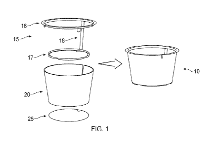
Referring now to Figure 1 there is shown a package generally indicated 10. The
exploded view
shows the package 10 to comprise a frame 15, a wraparound sidewall 20 and a
base 25.
The frame comprises an upper ring 16 and a lower ring 17 which are axially
spaced and joined
by an inclined stem/tether 18. The upper ring includes depending tab which in
use form around
notches formed in the sidewall.
6
CA 03175972 2022- 10- 18
WO 2021/214002
PCT/EP2021/060139
Figure 2 shows a partial section of the paperboard material used in this
embodiment for the
sidewall 20 and the base 25.
Figures 3 and 4 illustrates the lower ring 17 and shows that at its "bottom"
face (i.e. the face on
which the package will rest in use) a foot is formed by arcuate feet portions
18. The portions 18
are spaced by radially inwardly extending rims 19 on which the base 25 rests
in the package.
The foot protects the paperboard base against damage (wear and water damage)
during filling
and subsequent usage.
Figure 5 shows a blank used to form the sidewall 20. A punch line is shown in
solid line. The
blank is generally arcuate and includes two notches 22.
Figure 6 shows a blank used to form the base 25. A punch line is shown in
solid line.
Figures 7 and 8 relate to an overmoulding process used to form a package of
the type
described in relation to Figures 1 to 6.
In this embodiment a package is formed by first taking a wall blank of the
type shown in Figure
5 and a base blank of the type shown in Figure 6. The blanks are placed in
female mould
cavities (eight separate cavities are shown by way of example in Figure 8).
Illustrated in Figure 7 is: the areas 35 into which plastics material flows;
the paperboard blanks
37; and areas 39 of paperboard that are compressed/under pre-tension when the
male part of
the mould is closed onto the female part.
When the tool is closed, the paper is compressed on well-chosen surfaces to
ensure that the
plastic does not extend over it in an overmoulding step. The board does not
take up the entire
mould; the room that remains is filled with polypropylene, so the plastics
skeleton is fused to the
paper carton and becomes a structural member of the product.
Also illustrated in Figure 7 is a single limb 40 which extends radially
inwardly from the lower ring
of the frame. The free end 41 of the limb 40 is the gate point of the mould.
In this embodiment
this means an injection point approximately 17mm off centre. Also shown are
the tabs that
depend from the upper ring.
Figure 9 shows a package 110 formed according to a further embodiment in
assembled and
exploded views.
Figure 10 shows a package 110 of the type shown in Figure 9 and including a
lid 150. The lid
150 is a push-fit/snap-fit into the upper ring of the frame.
7
CA 03175972 2022- 10- 18
WO 2021/214002
PCT/EP2021/060139
In this embodiment the lid is formed from plastics materials. In other
embodiments a mixed
material lid is provided.
Figures 11 and 12 show perspective and side exploded views of a package formed
according to
a further embodiment. The formed package 210 is shown in Figures 13 to 15 and
17 to 20.
Stacked packages are shown in Figure 16.
Figures 21 10 23 are side, plan and perspective views of a package 310 formed
according to a
further embodiment. Figure 24 shows two packages of the type shown in Figures
21 to 23
stacked one on top of the other.
Figures 25 to 27 are side, plan and perspective views of a package 410 formed
according to a
further embodiment. Figure 28 shows two packages of the type shown in Figures
25 to 27
stacked one on top of the other.
Figures 29 to 34 show a package 510 formed according to a further embodiment.
Figures 35 to 41 show a package 610 formed according to a further embodiment.
In this
embodiment the package is generally rectangular/cuboidal.
Figures 42 and 43 show a package 710 formed according to a further embodiment
and shown
in assembled and exploded views. The package is generally rectangular.
Figures 44 to 46 illustrate a corner region of a package 810.
A ring 817 is shown, having a generally T-shape section. The section of the
ring 817 includes
an L-shape upper section 817a and an L-shape lower section 817b which
depending from the
corner of the upper section. A generally horizontal (in the drawing) leg of
the upper section is
formed against the base 825; a generally vertical leg of the upper section is
formed against the
sidewall 820. The base also abuts an inner surface of a longer leg of the
lower section. The
shorter leg of the lower section forms feet portions 818 and provide an
outward step. It will be
noted that the free end of the sidewall is formed against the step. It will
also be noted that the
plastic material only extends along the inner face of the sidewall; there is
only plastic on one
side and end.
Figure 46 shows that the plastics material is formed across all of the exposed
edge of the
sidewall, even across the gaps 819 (useful as an end point for labels, for
example). For
purposes of illustration, Figure 47 shows the corner region but with the frame
shown removed,
so that the sidewall and base can be seen clearly, with their exposed edges
being highlighted.
8
CA 03175972 2022- 10- 18 RECTIFIED SHEET (RULE 91) ISA/EP
WO 2021/214002
PCT/EP2021/060139
The foot protects the paperboard base and sidewall against damage (wear and
water damage)
during filling and subsequent usage. Exposed edges of the base and the
sidewall are covered
by material of the frame.
Figure 48 shows the wraparound sidewall in the region where its two ends
approach.
Figure 49 shows the upper ring 816 of the package. The ring 816 is formed with
depending
tabs 826 which mould around notches in the sidewall.
Figures 50A to 50D show progressively the flow of plastic material during
moulding. It will be
noted that the stem includes a feeder channel, allowing material to flow from
the lower 817 to
the upper ring 816. Only one channel is provided between the rings in this
embodiment.
Figures 51 to 58 illustrate a package 950 formed according to a further
embodiment. The
package 950 comprises base 960, a lid 970 and a sub-lid 980. The lid snap-
fits/clips onto the
base and the sub-lid snap-fits/clips into the lid. Other ways of connecting
the parts together
(e.g. screw thread formations, bayonet fixing means or the like) could be
provided. A void 990
is formed between the lid and the sub-lid.
The base 960 comprises a bottom disc 962 formed from laminated cardboard, a
generally
cylindrical (in this embodiment) wraparound sidewall 963 formed from laminated
cardboard and
a moulded-on frame formed from a plastics material and having an upper part
964 and a lower
part 965.
The lid 970 comprises an annular frame 972 formed from a plastics material and
a disc-like 974
insert formed from laminated cardboard.
The sub-lid 980 comprises a plug-like frame 982 formed from a plastics
material and a disc-like
top deck 984 formed from laminated cardboard.
The package shares certain similarities with the packages shown in Figures 1
to 51, including
exposed edges of laminated cardboard being covered by frame material. On the
base, for
example, the lower ring forms a corner (see especially Figures 56 and 57)
against which the
free edges of both the bottom disc and the sidewall abut. In this embodiment
the exterior of the
corner is formed as a chamfer 966 from which a radial step 967 projects (which
is formed onto
the exposed edge of the sidewall) and also an axial step 968 (which is formed
onto the exposed
edge of the bottom disc). For the bottom disc this means the lower surface is
not raised but it is
laminated/coated so it is protected from moisture ingress. Meanwhile the
exposed edge of the
base is protected by the chamfered corner.
Figure 58 shows the upper part of the base, the lid and the sub-lid.
9
CA 03175972 2022- 10- 18 RECTIFIED SHEET (RULE 91) ISA/EP
WO 2021/214002
PCT/EP2021/060139
The upper part 964 of the base includes a radial step 964a which is formed
onto the sidewall
963. The upper part also includes an external annular snap bead 964b.
The lid frame 972 includes an internal snap bead 972a which cooperates with
the bead 964b.
At the other end of the frame an axial step 972c is formed onto the insert
974. The frame also
includes an external snap bead 972d.
The frame of the sub-lid 980 is generally L-shape in section. A longer leg 981
terminates with a
snap bead 982 which cooperates with the bead 972d. A shorter leg 983
terminates with an
axial step 985 which is formed onto the exposed edge of the top deck 984.
In some embodiments the package is formed as a snuff box/chewing tobacco
container. The
void 990 can be used to store used tobacco, for example.
Figures 59A-F show a package 1010 formed according to a further embodiment. In
this
embodiment the package is generally square. Only a single limb 1040, a single
injection inlet
point 1 041 and a single connecting stem 1018 is used to form lower and upper
rings (which are
curved squares), with the upper ring being larger than the lower ring.
Figures 60 and 61 show a package 1110 formed according to a further
embodiment. Figure 63
shows the skeleton frame forming part of the package.
In this embodiment multiple (three, in this case) limbs 1141a-c are present,
providing three
separate corresponding inlet points 1140a-c and three corresponding stems
1118a-c used to
form lower 1117 and upper 1116 rings.
Figures 63 and 64 show a package 1210 formed according to a further
embodiment. Figure 66
shows the skeleton frame forming part of the package.
Figure 66 shows a wraparound sidewall blank 1220 formed in accordance with the
present
invention. The blank is removed (e.g. cut/stamped/punched) from a stock sheet
of fibre-based
material. It will be noted that as a result the orientation D of the fibres
can be controlled to be all
the same. Further, it will be appreciated that if the sidewall is formed only
by bending in a single
plane, the uni-directional orientation of the fibres will be maintained in the
final hybrid package.
This means, for example, that the fibres can be oriented to provide a
particular benefit. In some
embodiments the sidewall fibres have a generally axial orientation, meaning
that maximum
stiffness is provided in a top load direction L.
Figure 67 shows a sidewall 1320 formed in accordance with the present
invention.
Unidirectional fibre orientation is illustrated.
CA 03175972 2022- 10- 18 RECTIFIED SHEET (RULE 91) ISA/EP
WO 2021/214002
PCT/EP2021/060139
Figure 68 shows a sheet 1360 of fibre-based material including a plurality of
pre-cut sidewalls
1320.
Figures 69 to 71 show a package formed according to the present invention. In
this
embodiment a container 1410 and a separate, removable lid 1450 are provided.
The package is formed with a twist lock closing system, with the upper ring
and the lid being
provided with cooperating formations and forming a generally bayonet style
attachment. The lid
is rotated to move locking formation/s (e.g. lug/s) either axially under or
free of cooperating
locking surfaces (e.g. flanges) on the ring to lock/unlock when positioned on
the container.
Although illustrative embodiments of the invention have been disclosed in
detail herein, with
reference to the accompanying drawings, it is understood that the invention is
not limited to the
precise embodiments shown and that various changes and modifications can be
effected
therein by one skilled in the art without departing from the scope of the
invention as defined by
the appended claims and their equivalents.
11
CA 03175972 2022- 10- 18 RECTIFIED SHEET (RULE 91) ISA/EP