Note: Descriptions are shown in the official language in which they were submitted.
METHOD AND DEVICE FOR DETERMINING CENTERS OF A HOLLOW SHAFT
ROTATABLY CLAMPED AS A WORKPIECE IN A MACHINE TOOL
The invention relates to a technical solution for determining centers and the
spatial course
of these centers of a hollow shaft rotatably clamped as a workpiece in a
machine tool, which
is machined on its outer surface at least in sections.
It is known to determine centers for bores in a workpiece and to determine the
course of
the respective bores or centers on the basis of two or more bore centers. For
example,
when machining longer hollow shafts to accommodate turbine blades, it is
necessary to
align the averaged axis of the inner cavity with the axis of rotation of the
machine tool
rotating the hollow shaft. For this purpose, the inner radius of a large
number of points
inside the hollow shaft is measured and then an alignment of the hollow shaft
and the
machine tool is realized by means of a mathematically fictitiously determined
mean axis. If
the inner contour of the bore is measured tactilely, problems often arise due
to the length
of the tactile measuring elements used and the vibrations that occur. For this
reason, other
measuring methods are increasingly being used instead of tactile methods.
In EP 2 527 084 A2, for example, it is proposed for the reduction of
imbalances that hollow
shafts to be machined are first optically scanned in sections and that centers
of gravity or
imbalances are calculated in sections on the basis of these optically recorded
values.
These points or sections are subsequently milled in a targeted manner in order
to achieve
largely optimum concentricity of the hollow shaft for subsequent use.
DE 199 58 373 Al describes a method for reducing the eccentricity of the inner
to the outer
surface of a hollow workpiece rotatably clamped in a machine tool. Here,
ultrasound is used
to determine several measurement data dependent on the contour of the inner
surface.
These measurement data are used to calculate a nominal course of the outer
surface, and
the outer surface is subsequently machined according to the calculated nominal
course in
the same workpiece clamping as during the measurement.
A similar approach is described in EP 2 668 547 Bl. Here, however, the
measurement data
of the contour of the inner surface determined with ultrasound are used for
the calculation
for a part of the outer surface, which is at least partially machined in a
further process step.
The workpiece is re-clamped over the partial surfaces generated in this way
using clamping
1
CA 03176322 2022- 10- 20
devices such as chucks and steady rests, and the other outer surfaces of the
workpiece
are subsequently machined.
By generating new clamping seats in this way for further machining, largely
optimum
machining of hollow shafts is possible. However, the use of ultrasound to
measure the
contours in the inner cavity of larger hollow shafts (e.g. with a length of
more than 2 meters)
is only possible to a limited extent. This is because the technical complexity
of the
equipment increases considerably and the measuring accuracy is reduced at the
same
time. Therefore, in addition to optical and ultrasound-based solutions, the
fundamental aim
is to modify other measurement methods known per se for such applications.
WO 2012/100 278 Al describes a method for reducing the eccentricity of the
inner to the
outer surface of a hollow workpiece rotatably clamped in a machine tool. Here,
a user-
friendly and fast method for measuring the wall thickness of a workpiece with
the aid of an
ultrasonic measuring device is described. However, it remains unclear whether
the
procedure is carried out by contact (tactile) or with the aid of a carrier
medium for sound
transmission. It is described that the procedure is carried out on the outer
surface in the
circumferential direction or also preferably in the longitudinal direction of
the workpiece.
The ultrasonic measuring device is used to record measurement data with which
at least
one, in this case two, partial surfaces are generated, preferably by axis-
parallel rotary
milling. With the help of these partial surfaces, the workpiece is clamped in
a new setup,
but rotated by 180 degrees, which requires a manual operator action or
automation and is
not explicitly described. The wall thickness determined by the ultrasonic
process is subject
to the influence of the outer and inner contours and thus also of the clamping
device used.
Operator actions are required during the process.
Another technical solution for machining a workpiece is described in EP 2 572
826 Al.
Here, a tool is used which takes into account the deviation of the actual
rotational axis from
the nominal rotational axis of a workpiece by feeding the tool with the aid of
sensor
measurement data. The sensor measurement data are recorded by at least two co-
rotating
measuring means of known shape. These measuring means are each attached to the
end
face of the full workpiece and each have an annular and each have an at least
partially
spherical known shape. Measurement data are recorded by several inductively
operating
sensors, with the aid of which existing form and position deviations are
improved or reduced
by machining with a geometrically determined cutting edge in order to meet the
highest
2
CA 03176322 2022- 10- 20
geometric requirements. The machining process used is not described further.
The process
requires workpiece preparation on the workpiece face with the measuring
equipment to be
used. The sensors are aligned with the workpiece through an opening in the
clamping
device or starting from a tailstock.
It is the aim of the invention to create a new technical solution for
determining centers and
the spatial course of these centers of a hollow shaft rotatably clamped as a
workpiece in a
machine tool using methods other than ultrasound.
This aim is achieved in terms of process technology in that first of all the
radial distances
between the sensor and the workpiece contour are detected without contact over
at least
one full angle of the workpiece contour at at least two defined axial
positions in defined
angular relative positions between the axis of rotation of the sensor and the
axis of rotation
of the hollow shaft using at least one sensor operating according to the eddy
current
principle. Then, by calculating any constant radius to the detected radial
distances, a vector
is formed from polar coordinates with the values angle and radius with radial
distances,
which is converted into Cartesian coordinates. A geometric workpiece center
point
assignable to the corresponding axial position of the hollow shaft is
calculated via
averaging. Then, from at least two such calculated workpiece center points at
different axial
positions, a center axis lying in space is calculated by a regression
analysis, which
approximates the workpiece center points. Subsequently, starting from the
center axis
along the axis of rotation of the hollow shaft, any number of diameters
concentric to the
center axis is calculated, with which new clamping seats for the hollow shaft
are machined,
which redefine the axis of rotation of the hollow shaft concentrically to the
center axis. In
this case, the radial distances at at least two defined axial positions along
the axis of
rotation of the hollow shaft can be recorded with a sensor one after the other
in time.
Alternatively, it is also possible for these radial distances to be detected
with at least two
sensors simultaneously or one after the other in time.
To carry out the method, a device is proposed which is arranged in a fixed or
exchangeable
manner in the working space of a machine tool with the aid of a holder on a
tool carrier and
carries one or more sensors operating according to the eddy current principle
in the same
or definedly different alignment and design and can be freely positioned in
the working
space via at least one machine axis of the tool carrier. Advantageous
embodiments are the
subject of subclaims, which are explained in more detail in an embodiment
example.
3
CA 03176322 2022- 10- 20
With the technical solution according to the invention, a method and a device
become
available which enable a non-contact measurement in a large measuring range by
applying
the eddy current principle. Thus, by means of a distance measurement by eddy
current
technique, the bore centers are measured. Due to the calculation with a
virtual diameter,
the centers are determined independently of the concrete diameter, whereby
inner contours
are measured. The vibration-reducing components ensure high measuring accuracy
even
for long workpieces to be measured. As a result, (spatially) precisely
positioned clamping
seats and steady rest seats can be created on hollow shafts and similar
workpieces, which
are used for a new clamping of the workpiece in an optimal spatial orientation
for
subsequent machining. Thus, a technical solution is created for the generation
of clamping
seats for a new clamping of a workpiece rotatably clamped in a machine tool
with a free
contour section in the interior of the workpiece, which is machined on its
outer surface at
least in sections, wherein the center axis is calculated with the proposed
method and the
new clamping seats are manufactured with the proposed device. The measuring
process
as well as the subsequent machining process for producing the new clamping
seats is
carried out in an unmanned process.
The invention is explained in more detail below in an embodiment with
reference to the
drawing. It shows:
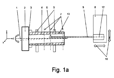
Fig. la the basic structure with representation of the operative connection of
the
assemblies during the measurement
Fig. lb a representation of the effective connection of the assemblies during
the milling
of new clamping seats concentric to the calculated center axis
Fig. lc a representation of the effective connection of the assemblies during
chucking
of the hollow shaft
Fig. ld a representation of the effective connection of the assemblies during
the milling
and turning of new clamping seats for further machining
Fig. le a representation of the effective connection of the assemblies in a
new clamping
situation
Fig. 2 the basic structure of the device for measured value
acquisition
Fig. 3 a representation of the vibration reducing components
Fig. 4 the structure of the device in a modified version
4
CA 03176322 2022- 10- 20
The technical device arrangement shown in the drawing is designed for carrying
out a
method for determining centers and the spatial course of these centers of a
workpiece
rotatably clamped in a machine tool with a free contour section in the
interior, preferably a
hollow shaft, which is machined on its outer surface at least in sections.
According to Fig. la, the workpiece, which is designed as a hollow shaft 4, is
clamped with
an end face section in a clamping means designed as a chuck 2. In addition,
the outer
surface of the hollow shaft 4 is supported in at least one further clamping
means. In the
example according to Fig. la, however, the support is not provided in just one
further
clamping means, but in two further clamping means designed as steady rests 5.
In this
supported position, the hollow shaft 4 rotates around the workpiece rotation
axis 1. The
direction of rotation is shown with a stylized arrow.
Fig. la also shows that the workpiece contour 13 is not concentric. Rather,
the outer
contour and the inner contour of the hollow shaft 4 run eccentrically to each
other. To
ensure that correct machining is nevertheless possible, centers are first
determined for the
hollow interior of the hollow shaft 4.
A device 9 shown on the right in Fig. la is provided for this purpose, the
basic structure of
which is again shown separately in Fig. 2. The device 9 is arranged in the
working area of
a machine tool, which is not shown in more detail here, with the aid of a
holder 14 on a tool
carrier 8. Both a fixed and an exchangeable arrangement are possible, with the
exchangeable variant being advantageous due to the possible use of cassettes.
The
machine axes of the tool carrier 8 are shown with two stylized arrows 10.
At least one sensor 6 operating according to the eddy current principle is
arranged on the
device 9. The axis of rotation referred to the sensor 6 is marked with the
reference sign 12.
However, the sensor 6 itself does not rotate about this axis of rotation 12.
If the device 9 is
equipped with several sensors 6, sensors 6 of the same or different design can
be provided
for this purpose. Likewise, the multiple sensors 6 can be arranged in the same
or defined
different orientation. Regardless of the specific number, design and
orientation, each
sensor 6 can be freely positioned in the working area of the machine tool via
at least one
machine axis 10 of the tool carrier 8.
5
CA 03176322 2022- 10- 20
In the embodiment shown, only one sensor 6 is provided. With this sensor 6,
which
operates according to the eddy current principle, the radial distances between
the sensor
6 and the workpiece contour 13 are detected at at least two defined axial
positions 7. Fig.
la shows three positions in this respect, whereby the sensor 6 is located here
at the middle
axial position 7 as an example. The contactless detection of the radial
distances takes place
in defined angular relative positions between the axis of rotation 12 of the
sensor 6 and the
axis of rotation 1 of the workpiece 4 over at least one full angle of the
workpiece contour
13.
If only one sensor 6 is used, the radial distances are detected at at least
two defined axial
positions 7 along the axis of rotation 1 of the hollow shaft 4 in succession.
If, on the other
hand, several sensors 6 are present, the radial distances are also recorded
either in
succession or, advantageously, simultaneously.
A qualitatively good recording of measured values is achieved if additional
vibration-
reducing components are assigned to the device 9. According to Fig. 3, several
disk-like
components 15 are structurally integrated in the interior of the device 9 for
this purpose.
These components 15 each have an elastic component in the circumferential
direction
which is radially braced with the device 9. The vibration-reducing components
15 also have
centrally and/or eccentrically arranged openings 16 for axial feed-through and
attachment
of cables and lines. Furthermore, it is provided that at least one vibration-
reducing
component 15 is rigidly connected to at least one adjacent vibration-reducing
component
15 and is attached to the holder 14 to the tool carrier 8. As a result, the at
least one sensor
6 rotating about the axis of rotation 12 performs very precise movements
without
deflections affecting the measurement.
The device 9 can be further designed to achieve a largely optimum adaptation
for specific
application requirements in each case. For example, the device 9 can be
arranged on an
extendable sensor carrier for hollow shafts 4 with long cavities. Furthermore,
the energy
required to operate the device 9 can be supplied either contactlessly or by
cable. In this
case, a contactless energy supply is designed, for example, as an inductive
power supply.
Furthermore, the measurement data acquired by means of the device 9 can be
transmitted
contactlessly or by cable to a computing unit with which the measurement data
can be
transmitted to a further computing unit of a control system of the associated
machine tool.
6
CA 03176322 2022- 10- 20
As soon as the radial distances between sensor 6 and workpiece contour 13 have
been
detected, a vector of polar coordinates with the values angle and radius with
radial
distances is formed by calculating any constant radius with the detected
radial distances.
This vector is converted into Cartesian coordinates and a geometric workpiece
center point
assignable to the corresponding axial position 7 of the hollow shaft 4 is
calculated by
averaging. Then, from at least two calculated workpiece center points at
different axial
positions 7, a center axis 3 lying in space is calculated by a regression
analysis, which
approximates the workpiece center points. Subsequently, starting from the
center axis 3
along the axis of rotation 1 of the hollow shaft 4, any number of diameters
concentric to the
center axis 3 are calculated.
With the diameters calculated in this way, new clamping seats are machined for
the hollow
shaft 4, which redefine the axis of rotation 1 of the hollow shaft 4
concentrically to the center
axis 3. This process step is shown in Fig. lb. The hollow shaft 4 continues to
be clamped
with a front end section in the clamping means designed as chuck 2 and rotates
about the
axis of rotation 1. In addition, the hollow shaft 4 is still supported with
its outer surface in
the steady rest 5 shown on the right, but no longer in the steady rest 5 shown
on the left.
The new clamping seats 24 are rotationally milled concentrically to the
calculated center
axis 3 orthogonally. Preferably, each new clamping seat 24 is created with a
turning / drilling
/ milling unit 20 by a respective associated milling tool 21. The traversing
axes of the turning
/ drilling / milling units 20 are each shown with two stylized arrows 19.
After the new clamping seats 24 are machined, the chucking of the hollow shaft
4 takes
place. This process step is shown in Fig. lc, where the arrow marked "A"
stylizes the
chucking of the hollow shaft 4 and a simultaneous process so that new clamping
seats can
be milled. For this purpose, the tool carrier 8 comprises a rotatable clamping
means 17,
which is designed to be selectively drivable and lockable. The clamping means
17 is
designed for an inner or outer receptacle of the hollow shaft 4 and can be
actuated manually
or automatically. The clamping means 17 is freely positionable in the working
space of the
machine tool via at least one machine axis 10 of the tool carrier 8. Fig. 4
shows this
equipment design again separately.
According to Fig. lc, the hollow shaft 4 is released from the clamping means
designed as
chuck 2 and is supported on the new clamping seats via the steady rest 5 shown
on the
left and the clamping means 17 on the tool carrier 8. The clamping device 17
rotates about
7
CA 03176322 2022- 10- 20
a rotation axis 18 so that the hollow shaft 4 also executes a rotating
movement. In this
clamping situation, the workpiece rotation axis 1, center axis 3 and clamping
device rotation
axis 18 are congruent with each other.
This is followed by milling and turning of new clamping seats 24 for further
machining. This
process step is shown in Fig. ld. The hollow shaft 4 is further released from
the clamping
means designed as chuck 2 and supported via the steady rest 5 shown on the
left and the
clamping means 17. The turning / drilling / milling units 20 already explained
for Fig. lb are
used for machining. Instead of two milling tools 21, one milling tool and one
turning tool 22
are now used, for example.
Fig. le shows the clamping situation after milling and turning the new
clamping seats 24.
The hollow shaft 4 is now clamped again in the clamping means designed as
chuck 2 and
rotates about the workpiece rotation axis 1, which is congruent with the
calculated center
axis 3. In addition, the hollow shaft 4 is supported with its outer surface in
the steady rest
5 shown on the right, but not in the steady rest 5 shown on the left.
8
CA 03176322 2022- 10- 20
List of reference symbols
1 Rotation axis workpiece / hollow shaft
2 Clamping device / chuck
3 Center axis
4 Workpiece / hollow shaft
5 Clamping device / steady rest
6 Sensor
7 Axial positions for determining center point
8 Tool carrier
9 Device for measured value recording
10 Machine axes of the tool carrier
12 Rotation axis of sensor
13 Workpiece contour
14 mounting
15 disk-like components for vibration reduction
16 Cable, media, fastening openings
17 Clamping device
18 Rotational axis clamping device
19 Traversing axes
20 Turning / drilling / milling unit
21 Milling tool
22 Turning tool
24 Clamping seat
9
CA 03176322 2022- 10- 20