Note: Descriptions are shown in the official language in which they were submitted.
WO 2021/214768
PCT/IL2021/050456
RESUSCITATION DEVICE
FIELD OF INVENTION
The present disclosure generally relates to resuscitation devices.
BACKGROUND
A primary task of the heart is to pump oxygenated, nutrient-rich blood
throughout the
body. Electrical impulses generated by a portion of the heart regulate the
pumping cycle. When
the electrical impulses follow a regular and consistent pattern, the heart
functions normally and
the pumping of blood is optimized. When the electrical impulses of the heart
arc disrupted (i.e.,
cardiac arrhythmia), sudden cardiac arrest may result, which inhibits the
circulation of blood.
As a result, the brain and other critical organs are deprived of nutrients and
oxygen. A person
experiencing sudden cardiac arrest may suddenly lose consciousness and die
shortly thereafter
if left untreated.
A well known and effective treatment for sudden cardiac arrest or arrhythmia
is
defibrillation. Defibrillation involves passing a current through the person
to shock the heart
back into a normal rhythm. There are a wide variety of resuscitation devices.
For example,
implantable cardioverter-resuscitation devices (-ICD") involve surgically
implanting wire coils
and a generator device within a person. ICDs are typically for people at high
risk for a cardiac
zo arrhythmia. When a cardiac arrhythmia is detected, a current is
automatically passed through
the heart of the user with little or no intervention by a third party.
Another, more common type of resuscitation device is the automated external
resuscitation device ("AED''). Rather than being implanted, the AED is an
external device used
by a third party to resuscitate a person who has suffered from sudden cardiac
arrest. A
conventional AED includes a base unit and two pads connected to the base unit
using electrical
cables. Sometimes electrodes with handles are used instead of the pads.
A typical protocol for using the AED on a subject who has suffered from sudden
cardiac arrest (the "patient") is as followed. The patient is initially placed
on the floor. Clothing
on the subject is removed to reveal the chest. The AED pads are applied to
appropriate
locations on the chest. The electrical system within the base unit generates a
high voltage
between the two pads, which delivers an electrical shock to the subject.
Ideally, the shock
restores a normal cardiac rhythm, and in some cases, multiple shocks are
required.
- 1 -
CA 03176338 2022- 10- 20
WO 2021/214768
PCT/IL2021/050456
SUMMARY
The following embodiments and aspects thereof are described and illustrated in
conjunction with systems, tools and methods which are meant to be exemplary
and illustrative,
not limiting in scope.
There is provided, in accordance with an embodiment, a resuscitation device,
including
an electric pulse generator configured to generate an electric pulse that is
administered to a
subject, electrodes operative to administer the electric pulse to the subject,
one or more sensors
configured to measure vital signs of the subject, one or more processing units
configured to
monitor the vital signs measured by the one or more sensors, determine the
housing and
electrodes are properly placed on the subject according to the monitoring of
the vital signs,
determine what treatment has to be administered to the subject, generate
notification
instructing the treatment to be administered to the subject, and providing
real-time, continuous
feedback of treatment provided and condition of the subject.
In some embodiments, the electric pulse generator includes an electrical
circuit for
generating an electric pulse, said electric circuit includes a controller, a
switch, an inductor, a
charging circuit, and a capacitor array electrically connected to the charging
circuit and adapted
to store energy supplied by the charging circuit, where the controller is
adapted to control the
switch to cause energy to be stored in the inductor and discharged to the
charging circuit.
In some embodiments, the controller is a controller and gate driver chip, the
inductor is
zo a low-profile boost inductor, and the charging circuit is a plurality of
interconnected charging
capacitors and diodes.
In some embodiments, the controller chip, the switch, and charging capacitor
are
surface mount components.
In some embodiments, the circuit includes an electric pulse generator for a
low profile
AED.
In some embodiments, the capacitor array includes a plurality of
interconnected discrete
energy-storing capacitors capable of storing up to a predetermined amount of
bi-phasic electric
pulse energy.
In some embodiments, the capacitor array has a total capacitance of at least
100
microfarads and 1.5 kilovolts to provide at least 150 joules of energy
storage.
In some embodiments, the resuscitation device further includes a communication
unit
configured to communicate with a mobile device, the mobile device configured
to present the
user with user interface and instructional content, receive user commands for
administering the
electric pulse to the subject, transmit the user commands to the communication
unit.
- 2 -
CA 03176338 2022- 10- 20
WO 2021/214768
PCT/IL2021/050456
In some embodiments, the resuscitation device further includes a housing, a
case
operative to store the housing and the electrodes.
In some embodiments, the resuscitation device further includes a case, an
activation
switch, a sensor case configured to detect when the case is opened, where the
processor is
configured to switch from a sleep mode to a hibernation mode when the case
sensor detects the
case is opened, switch to an active mode when the activation switch is
engaged.
There is further provided in accordance with an embodiment, a system including
a
resuscitation device configured to measure and monitor vital signs of a
subject, administer an
electric pulse to the subject, provide instruction to a treatment provider of
the treatment
provided to the subject, one or more mobile devices configured to be in
wireless
communication with the resuscitation device, the v configured to, receive the
vital signs,
present a user of the mobile device with a user interface configured to,
display the vital signs,
and obtain commands from the user that are provided to resuscitation device,
transmit the
commands to the resuscitation device, the resuscitation device executes the
commands received
from the mobile device.
In some embodiments, the resuscitation device is further configured to
recognize that
the mobile device is within a predetermined distance from the resuscitation
device, receive
authentication information from the mobile device, determine the
authentication information
matches a stored authentication information, grant the mobile communication
access to
communicate with the resuscitation device.
In some embodiments, the resuscitation device is further configured to
determining a
plurality of mobile device have authority to access the resuscitation device,
allow access to the
mobile device having a highest priority according to a priority hierarchy.
In some embodiments, the resuscitation device includes one or more sensors
configured
to measure the vital signs, an electric pulse generator configured to generate
the electric pulse,
at least two electrodes configured to administer the electric pulse.
In some embodiments, the electric pulse generator includes a capacitor array
configured
to facilitate storing the electric pulse prior to administration.
In some embodiments, the resuscitation device further includes a tarp
operative to
facilitate covering the chest of the subject during administration of medical
treatment.
There is further provided in accordance with an embodiment, a resuscitation
device
configured to administer an electric pulse to a subject, including electrodes
operative to
administer an electric pulse to a body of the subject, and an electric pulse
generator configured
- 3 -
CA 03176338 2022- 10- 20
WO 2021/214768
PCT/IL2021/050456
to generate the electric pulse that is administered to via the electrodes to
the subject, the
electric pulse generator including an electric circuit configured to store an
electric charge
sufficient to generate the electric pulse.
In some embodiments, the resuscitation device further includes one or more
sensors
configured to measure vital signs of the subject, one or more processing units
configured to
monitor the vital signs measured by the one or more sensors, determine the
housing and
electrodes are properly placed on the subject according to the monitoring of
the vital signs,
determine what treatment has to be administered to the subject, generate
notification
instructing the treatment to be administered to the subject, providing real-
time, continuous
feedback of treatment provided and condition of the subject.
There is further provided in accordance with an embodiment, an electrical
circuit for
generating an electric pulse, including a controller, a switch, an inductor, a
charging circuit,
and a capacitor array electrically connected to the charging circuit and
adapted to store energy
supplied by the charging circuit, where the controller is adapted to control
the switch to cause
energy to be stored in the inductor and discharged to the charging circuit.
In some embodiments, the controller is a controller and gate driver chip, the
inductor is
a low-profile boost inductor, and the charging circuit is a plurality of
interconnected charging
capacitors and diodes.
In some embodiments, the controller chip, the switch, and charging capacitor
are
zo surface mount components.
In some embodiments, the circuit includes an electric pulse generator for a
low profile
AED.
In some embodiments, the capacitor array includes a plurality of
interconnected discrete
energy-storing capacitors capable of storing up to a predetermined amount of
bi-phasic electric
pulse energy.
In some embodiments, the capacitor array has a total capacitance of at least
100
microfarads and 1.5 kilovolts to provide at least 150 joules of energy
storage.
In addition to the exemplary aspects and embodiments described above, further
aspects
and embodiments will become apparent by reference to the figures and by study
of the
following detailed description.
BRIEF DESCRIPTION OF THE DRAWINGS
Some non-limiting exemplary embodiments or features of the disclosed subject
matter
are illustrated in the following drawings.
- 4 -
CA 03176338 2022- 10- 20
WO 2021/214768
PCT/IL2021/050456
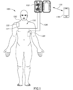
Fig. 1 shows a resuscitation device connected to a subject for administering
an electric
pulse, according to certain exemplary embodiments;
Figs. 2A-2C schematically illustrates the resuscitation device in various
configurations,
according to certain exemplary embodiments;
Fig. 3 schematically illustrates a system for operation of the resuscitation
device,
according to certain exemplary embodiments;
Fig. 4 schematically illustrates an electrical circuit of the resuscitation
device of Fig. 3
configured for charging the electric pulse generator, according to certain
exemplary
embodiments;
Fig. 5 schematically illustrates a capacitor array of the electrical circuit
of Fig. 4,
according to certain exemplary embodiments;
Fig. 6 outlines operations of a method for connecting the resuscitation device
with a
mobile device, according to certain embodiments; and,
Fig. 7 outlines operations of a method for administering the electric pulse to
the subject,
according to exemplary embodiments; and,
Fig. 8 outlines operations of a method for activating the resuscitation
device, according
to certain exemplary embodiments.
Identical, duplicate, equivalent or similar structures, elements, or parts
that appear in
one or more drawings are generally labeled with the same reference numeral,
optionally with
zo
an additional letter or letters to distinguish between similar entities or
variants of entities, and
may not be repeatedly labeled and/or described.
Dimensions of components and features shown in the figures are chosen for
convenience or clarity of presentation and are not necessarily shown to scale
or true
perspective. For convenience or clarity, some elements or structures are not
shown or shown
only partially and/or with different perspective or from different point of
views. References to
previously presented elements are implied without necessarily further citing
the drawing or
description in which they appear.
DETAILED DESCRIPTION
Disclosed herein is a system and method for administering resuscitation,
according to
certain exemplary embodiments.
Fig. 1 schematically illustrates a resuscitation device 100 for administering
an electric
pulse to a subject 185, according to certain embodiments. Resuscitation device
100 includes
electrodes 120, 125 that are positioned on a body 190 of subject 185 during an
arrythmia
- 5 -
CA 03176338 2022- 10- 20
WO 2021/214768
PCT/IL2021/050456
incident. Resuscitation device 100 is configured to pass electric pulses of a
selected shape and
size through body 190 via electrodes 120 and 125. Electrodes 120 and 125 are
connected by
leads 121 and 126, respectively, to resuscitation device 100. In some
embodiments, electrodes
120, 125 are configured to measure vital signs when attached to body 190
thereby facilitating a
treatment provider (not shown) to monitor a condition of subject 185 and
determining the
necessary treatment required and whether an electric pulse needs to be
administered, as further
described in conjunction with Fig. 3. Resuscitation device 100 is configured
to communicate,
represented by arrow 175, with a mobile device 170 that is operated by the
treatment provider
as described in conjunction with Figs 3 and 7.
Fig. 2A-2C schematically illustrates resuscitation device 100, according to
certain
exemplary embodiments. Fig. 2A shows resuscitation device 100 having a housing
200,
according to certain embodiments. Housing 200 is configured to provide
convenient carrying
and storage of resuscitation device 100 when it is not in use. In some
embodiments, housing
200 includes a power access port 205 configured to provide access to a power
source 315 (Fig.
3), for example, for replacement of a battery or to connect resuscitation
device to an external
power source such as an electrical socket. Housing 200 include a clip 210
configured to close
housing 200 and prevent it from opening when resuscitation device 100 is not
in use.
Fig. 2B shows an open configuration of resuscitation device 100. according to
certain
exemplary embodiments. Prior to operation of resuscitation device 100, housing
is opened to
zo
expose an internal storage area, referenced as 215, for storing electrodes
120, 125, leads 121,
126, a user interface 220, or the like. Internal storage area 215 includes a
connector 240 for
connecting leads 125, 126 to resuscitation device 100.
Fig. 2C shows user interface 220, according to certain embodiments. User
interface 220
includes a power button 225, a pulse administration button 230 and an
instruction interface 235
to provide the treatment provider with instructions for operating the
resuscitation device 100.
Instruction interface 235 can include pictures, diagrams or the like that show
the operating
procedures for resuscitation device 100.
In some embodiments, resuscitation device 100 is configured to toggle in and
out of a
low power mode, via opening of housing 200 or engagement of power button 225.
When
resuscitation device 100 is powered up for the first time, it performs a
series of power tests
after which it waits for electrodes 120, 121 to be attached to subject 190.
Fig. 3 schematically illustrates components of resuscitation device 100,
according to
certain exemplary embodiments. Resuscitation device 100 includes one or more
processors
300, a communication unit 305, an indication unit 310, power source 315 and an
electric pulse
- 6 -
CA 03176338 2022- 10- 20
WO 2021/214768
PCT/IL2021/050456
generator 320. Electrodes 120, 125 include one or more sensors referenced
generally 302, 304,
configured to measure vital signs of subject 185 (Fig. 1) when electrodes 120,
125 are attached
to body 190 (Fig. 1). In some embodiments, the vital signs can include heart
rate, blood
pressure, breathing rate, or the like.
Communication unit 305 can be configured to connect and communicate,
represented
by arrow 175, with mobile device 170. In some embodiments, mobile device 170
is operated
by an authorized treatment provider. Communication unit 305 can be configured
to
continuously transmit the vital signs in real-time to mobile device 170 and to
receive
commands from mobile device 170, for example, a command to administer an
electric pulse to
the subject 190.
Mobile device 170 can include an application executed by mobile device 170 to
present
a mobile user interface 325 configured to display the vital signs received
from resuscitation
device 100. Mobile user interface 325 can include an input through which the
treatment
provider can input a command to administer an electric pulse to the subject.
In some
embodiments, mobile user interface 325 can include a display that shows a
tutorial video
provided by the application that assists the treatment provider with operating
resuscitation
device 100. In some embodiments, mobile device 170 can provide an audio
tutorial to assist
with operating resuscitation device 100.
Indication unit 310 can be configured to provide audio and visual instruction
for
zo
placement of electrodes 120, 125 onto subject 185 and for administration of
an electric pulse to
subject 185. Electric pulse generator 320 generates the electric pulse that is
administered to
subject 185 through electrodes 120, 125.
Processor 300 is configured to operate resuscitation device and to regulate
communication with mobile device 170 as described in conjunction with Figs. 4-
5.
Electric pulse generator 320 is preferably configured to include a capacitor
flat pack
array 405 (Fig. 4) to replace a capacitor for generating the electric pulse.
Reference is now
made to Fig. 4., schematically illustrating an electric circuit 600 of
electric pulse generator 320,
according to certain embodiments.
In some embodiments, resuscitation device 100 can also includes a case sensor
325
configured to detect when case 200 (Fig. 2) is opened. Resuscitation device
100 can remain in
a hibernation mode while case 200 remains closed. In such embodiments, when
case 200 is
opened, case sensor 325 detects the opening of case 200 which switches
resuscitation device
100 from the hibernation mode to a sleep mode. During sleep mode,
resuscitation device 100
can execute periodic self-tests and wait to detect a microcurrent or other
signal from electrodes
- 7 -
CA 03176338 2022- 10- 20
WO 2021/214768
PCT/IL2021/050456
120, 125. Upon detection of a microcurrent or any other predetermined
condition, resuscitation
device 100 can switch to a full operation mode during which an electric pulse
can be
administered. In some embodiments, electric pulse generator 320 automatically
initiates the
charging of an electric charge for use as an electric pulse once resuscitation
device 100
switches to sleep mode.
Reference is made to Fig. 4, schematically illustrating an exemplary
electrical circuit
400 of electric pulse generator 320 configured for generating the electric
pulse to be
administered to subject 185, according to certain exemplary embodiments.
Electrical circuit
400 schematically represents a low-profile charging circuit including a
controller and gate
driver chip 410, a low-profile boost inductor 420, a semiconductor switch 430,
a plurality of
charging capacitors 450, a plurality of in-parallel, alternating direction,
charging diodes 460,
and an output energy storage capacitor array 405. Electrical circuit 400 is
configured to enable
a treatment charge to be accumulated and stored therein, facilitating a bi-
phasic electric pulse
discharge to subject 185 (Fig. 1) during defibrillation thereby returning
subject 185 to sinus
rhythm. Once discharged, electric circuit 400 may recharge output energy
storage capacitor
array 405 for a subsequent electric pulse discharge that can be delivered by
electric pulse
generator 320.
This circuit design enables a "very low profile" charging topology for any
electric pulse
generator requiring such a low profile form factor, whether used in a portable
AED or other
zo applications. Using a multiplicity of diodes 460 and charging capacitors
450 and replacing the
transformer typically found in the pulse generators of many AED' s with boost
inductor 420 for
the charging circuit is advantageous because it allows for lower overall
circuit height (low
physical profile). One primary reason is that inductor 420, while similar in
construction to a
transformer in that both entail windings, needs to store less energy in this
circuit design than in
other designs and consists of only a single winding, whereas a larger
transformer requires at
least two windings. This lower profile component enables a reduced height for
enclosing
charging circuit 400. In some embodiments, other components in electrical
circuit 400 are
preferably very low profile "surface mount' components.
Fig. 5 schematically illustrates in greater detail capacitor array 405 of
electrical circuit
400, according to certain exemplary embodiments. Capacitor array 405 is
configured to store
the necessary bi-phasic electric pulse energy amongst a plurality of series
and parallel
connected discrete capacitors 500. In some embodiments, capacitor array 405
stores a bi-phasic
electric pulse energy of 150 Joules. While a single capacitor could meet all
electrical
requirements for electric pulse generator 320, capacitor array 405 facilitates
a more flexible
- 8 -
CA 03176338 2022- 10- 20
WO 2021/214768
PCT/IL2021/050456
packaging of the overall electric pulse generator 320 than a single capacitor,
thereby further
enabling a reduction in the size dimension of resuscitation device 100,
enabling an extremely
compact, portable design.
Turning back to Fig. 4, combining these space saving designs in circuit 400
may enable
the form factor of electric pulse generator 320 and in turn, resuscitation
device 100 to be very
compact. For example, in some embodiments, resuscitation device 100 designed
with electric
charging circuit 400 can have a height within a range of 1-1.5 inches, a
length within a range of
6-6.50 inches and a width within a range of 3.6-3.65 inches.
In operation, controller chip 410 controls switch 430 to turn on and thereby
drive
current through boost inductor 420 resulting in energy stored in the magnetic
field of inductor
420. Controller 410 thereafter turns off switch 420, thereby allowing inductor
420 to discharge
through the multiplicity of charging diodes 460 and into charging capacitors
450. Controller
chip 410 monitors output voltage which accumulates in storage capacitor array
405 and adjusts
the duty cycle of switch 430 to regulate the output voltage and thus the
energy stored in the
capacitor array 405.
Capacitor array 405 includes an array of a predetermined number of capacitors
500, and
in the present embodiment 12 capacitors, configured to provide requisite
energy accumulation
and storage of the electric pulse energy. For example, capacitor array 405 can
include a number
of capacitors 500 within a range of 9-16. In some applications, the number of
storage
zo capacitors in array 500 may be as few as 2 and as many as 64 or more. In
certain cases, where
capacitor array 405 includes twelve capacitors 500 as shown, each capacitor
500 can have a
capacitance of 140 Microfarads ("FF") and voltage rating of 425 Volts ("V")
each, thereby
achieving a total capacitance of 1051.iF and 1.7 kilovolts ("kV") to provide
approximately 150
Joules of energy storage.
Reference is made back to Fig. 3. Mobile device 170 can execute an application
that
provides a user of mobile device 170, such as a treatment provider, with a
user interface 325
that enables the treatment provider to communicate with resuscitation device
100 and monitor
the vital signs and condition of subject 185. User interface 325 can present
video and audio
instructions to the treatment provider facilitating the operation of
resuscitation device 100 and
to enable treatment provider to provide commands to resuscitation device 100.
For example,
treatment provider can command resuscitation device 100 to administer an
electric pulse
through user interface 325. User interface 325 can display an instructional
video presentation
providing step-by-step instructions to the user to correctly operate
resuscitation device 100, for
example, a video and audio instructional that after each instructional step
gives the provider
- 9 -
CA 03176338 2022- 10- 20
WO 2021/214768
PCT/IL2021/050456
time to perform the step. Resuscitation device 100 can provide mobile device
100 with real-
time feedback about performance of the step and user interface 178 can provide
the treatment
provider with additional instructional material, repeat the instructional step
or continue to the
next step according to the performance of the treatment provider.
Reference is now made to Hg. 6, outlining operations executed by processor 300
(Fig.
3) to associate resuscitation device 100 (Fig. 1) with mobile device 170 (Fig.
1), according to
certain embodiments. When emergency services are notified of a medical
emergency requiring
operation of resuscitation device 100, the emergency services can notify a
treatment provider
of the incident and the treatment provider is dispatched to the event. The
treatment provider
can be dispatched according to vicinity to the resuscitation device 100, which
can be
determined by registration of resuscitation device 100 with a location-based
crowdsourcing
platform or, in conjunction with any conventional geo-locating technology,
with medical
services within a predetermined area, such as a city, district, state, and/or
the like.
When the treatment provider is within a predetermined distance from
resuscitation
device 100, processor 300 executes operation 600 detecting whether mobile
device 170 is
within a predetermined distance from resuscitation device 100. Processor 300
detects whether
mobile device 170 is within a predetermined distance from resuscitation device
100, for
example from pings received from mobile devices near resuscitation device 100.
For example,
the distance can be within a 1-meter radius from a location of resuscitation
device 100.
In operation 605, processor 300 receives authentication information from
mobile device
170 from communication unit 305. Communication unit 305 receives the
authentication
information from mobile device 170 as described in conjunction with Fig. 3.
In operation 610, processor 300 determines whether mobile device 170 has a
necessary
authorization to enable communication between to resuscitation device 100 and
mobile device
170. In some embodiments, processor 300 compares the authentication
information received
from mobile device 170 with stored authentication information. The stored
authentication
information can be authentication information that is registered with
resuscitation device 100
prior to a medical emergency, for example, during production, first time
activation and/or the
like. The stored authentication information can include authentication
information for all
treatment providers within a predetermined area such as a city, district,
and/or the like, or can
be of predetermined organizations such as the red cross, first aid responders
and/or the like. In
certain embodiments, registration can be achieved through crowdsourcing
platforms.
Where the authentication information matches the stored authentication
information,
processor executes step 615 enabling communication 175 (Fig. 1) between
resuscitation device
- 10 -
CA 03176338 2022- 10- 20
WO 2021/214768
PCT/IL2021/050456
100 and mobile device 170. Where the authentication information does not match
the stored
authentication information mobile device 170, processor 300 executes step 620
denying mobile
device 170 access to resuscitation device.
In certain exemplary embodiments, multiple mobile devices may have
authentication
information that will enable communication with resuscitation device 100. In
such cases a
hierarchy of authentication can be stored in resuscitation device 100, and
processor 300
executes optional step 625 to determine a priority of mobile device 170.
According to the
priority of mobile device 170, processor 300 prioritizes mobile device 170
over other mobile
devices according to the hierarchy of authentication based on the
authentication information of
mobile device 170 and executes step 430 to enable communication with mobile
device 170
with highest priority.
In operation 635, processor 300 initiates outputting of instructional material
for
operation of resuscitation device 100. Processor 300 provides the command to
communication
unit 305, which transmits the command to mobile device 170. Upon receipt of
the command,
mobile device 170 initiates instructional presentation in the application of
mobile device 170.
The instructional presentation can be in the form of a video and/or audio
presentation that
guides the user of mobile device 170 to properly position electrodes 120, 125
(Fig. 1) on
subject 185 and when to administer an electric pulse to subject 190.
Fig. 7 outlines operations executed by processor 300 (Fig. 3) for
administering
treatment to the subject, according to exemplary embodiments.
In operation 700. processor 300 monitors vital signs which it receives from
sensors 302,
304 (Fig. 3) in electrodes 120, 125 (Fig. 1). In some embodiments, sensors
302, 304 activate
once the seal covering electrodes 120, 125 is removed.
In operation 705 processor 300 determines whether electrodes 120, 125 (Fig. 1,
3) have
been positioned at designated locations on subject 185 (Fig. 1). Processor 300
determines
proper positioning of electrodes 120, 125 according to the vital signs
measured by sensors 302,
304 in electrodes 120, 125.
In operation 708, processor 300 generates a notification for mobile device 170
informing the user whether electrodes 120, 125 are positioned at the
designated locations.
Processor 300 transfers the notification to communication unit 305 which
transmits the
notification to the mobile device 170. In some embodiments, the notification
is accessible via
user interface 325 (Fig. 1). The notification can inform the user that
electrodes 120, 125 are
properly positioned at the designated locations or that they are not properly
positioned and
- 1 1 -
CA 03176338 2022- 10- 20
WO 2021/214768
PCT/IL2021/050456
must be moved to the designated locations, after which processor 300 executes
operations 500,
505 and 508 until electrodes 120, 125 are properly placed.
In operation 710, processor 300 operates communication unit 310 to transmit
the vital
signs to mobile device 170, which are then be displayed on user interface 325.
Processor 300
operates communication unit 305 (Fig. 3) to continuously transmit in real time
the vital signs
measured by sensors 302, 304 to mobile device 170. Through monitoring of the
vital signs
transmitted to mobile device, the treatment provider can assess the condition
of the subject and
determine the best course of treatment.
In operation 712, processor 300 assess the status of the subject 185 and
generates a
treatment recommendation. Processor 300 analyzes the vital signs thereby
making an
assessment of the condition of the subject 185. In some embodiments, the
analysis is achieved
by comparing the vital signs obtained by sensors 302, 304 with and determines
the treatment
necessary to subject 185. For example, processor 300 can determine subject 185
is suffering
from heart arrythmia and therefore an electric pulse must be administered to
subject 185.
In operation 715, processor 300 generates a notification instructing the
necessary
treatment for the subject, which is transmitted by communication device 305 to
mobile device
170.
In operation 725, processor 300 generates a pulse administration notification
to notify
treatment administer to administer an electric pulse to the subject 185. The
notification is
zo
transmitted by communication unit 305 to mobile device 170 to be displayed on
user interface
325 to enable treatment provider with the ability to provide a command to
administer the
electric pulse.
In operation 730, processor 300 receives a command to administer an electric
pulse to
the subject 325.
In operation 740, processor 300 administers the electric pulse to the subject
190.
Processor 300 operates electric pulse generator 169 to generate an electric
pulse that is
administered to subject 185 via electrodes 120, 125. After administration of
the electric pulse,
processor 300 continuously executes operations 710, 712, 715 and operation
725, 730 if
necessary.
Fig. 8 outlines operations of a method for activating the resuscitation device
100 (Fig.
1), according to certain exemplary embodiments. In operation 800, processor
300 (Fig. 3)
detects whether an activation operation has occurred. Resuscitation device 100
is configured to
remain in a hibernation mode as long as case 200 (Fig. 2) remains sealed. Case
sensor 325 (Fig.
3) detects that case 200 is opened and transmits a signal to processor 300.
- 12 -
CA 03176338 2022- 10- 20
WO 2021/214768
PCT/IL2021/050456
In operation 805, processor 300 switches to a sleep mode. After processor 300
receives
the detection that case 200 is opened, it switches from the hibernation mode
to the sleep mode
at which time. During sleep mode, processor 300 waits to receive a detection
of microcurrent
which signals to the processor 300 to switch to an active mode. In some
embodiments. during
sleep mode, processor 300 executes periodic internal diagnostic tests to
ensure proper
operation of resuscitation device 100 and operate electric pulse generator 320
(Fig. 3) to
commence charging the electric charge that can be used to administer the
electric pulse.
In operation 810, processor 300 detects a microcurrent. In some embodiments,
the
microcurrent can be detected by sensors 302, 304 (Fig. 3) when a cover (not
shown) is
removed from electrodes 120, 125 (Fig. 1), when electrodes 120, 125 are
removed from a pack
(not shown), when plastic line (not shown) is removed from electrodes 120,
125, or the like.
In operation 815, processor 300 switches to active mode. Upon detection of the
microcurrent, processor 300 switches to active mode, which commences the
operation of
resuscitation device 100 in a configuration to administer the electric pulse,
to monitor the vital
signs of subject 185 (Fig. 1), communicate with mobile device 170 (Fig. 1),
and the like.
In operation 820. processor 300 contacts emergency medical services.
In operation 825, processor transmits a GPS location message to emergency
medical
services.
In the context of some embodiments of the present disclosure, by way of
example and
zo without limiting, terms such as 'operating' or 'executing' also imply
capabilities, such as
'operable' or 'executable', respectively.
Conjugated terms such as, by way of example, 'a thing property' implies a
property of
the thing, unless otherwise clearly evident from the context thereof.
The terms 'processor' or 'computer', or system thereof, are used herein as
ordinary
context of the art, such as a general purpose processor or a micro-processor,
RISC processor, or
DSP, possibly comprising additional elements such as memory or communication
ports.
Optionally or additionally, the terms 'processor' or 'computer' or derivatives
thereof denote an
apparatus that is capable of carrying out a provided or an incorporated
program and/or is
capable of controlling and/or accessing data storage apparatus and/or other
apparatus such as
input and output ports. The terms 'processor' or 'computer' denote also a
plurality of processors
or computers connected, and/or linked and/or otherwise communicating, possibly
sharing one
or more other resources such as a memory.
The terms 'software', 'program', 'software procedure' or 'procedure' or
'software code' or
'code' or 'application' may be used interchangeably according to the context
thereof, and
- 13 -
CA 03176338 2022- 10- 20
WO 2021/214768
PCT/IL2021/050456
denote one or more instructions or directives or circuitry for performing a
sequence of
operations that generally represent an algorithm and/or other process or
method. The program
is stored in or on a medium such as RAM, ROM, or disk, or embedded in a
circuitry accessible
and executable by an apparatus such as a processor or other circuitry.
'the processor and program may constitute the same apparatus, at least
partially, such as
an array of electronic gates, such as FPGA or ASIC, designed to perform a
programmed
sequence of operations, optionally comprising or linked with a processor or
other circuitry.
The term computerized apparatus or a computerized system or a similar term
denotes an
apparatus comprising one or more processors operable or operating according to
one or more
programs.
As used herein, without limiting, a module represents a part of a system, such
as a part
of a program operating or interacting with one or more other parts on the same
unit or on a
different unit, or an electronic component or assembly for interacting with
one or more other
components.
As used herein, without limiting, a process represents a collection of
operations for
achieving a certain objective or an outcome.
As used herein, the term 'server' denotes a computerized apparatus providing
data
and/or operational service or services to one or more other apparatuses.
The term 'configuring' and/or 'adapting' for an objective, or a variation
thereof, implies
using at least a software and/or electronic circuit and/or auxiliary apparatus
designed and/or
implemented and/or operable or operative to achieve the objective.
A device storing and/or comprising a program and/or data constitutes an
article of
manufacture. Unless otherwise specified, the program and/or data are stored in
or on a non-
transitory medium.
In case electrical or electronic equipment is disclosed it is assumed that an
appropriate
power supply is used for the operation thereof.
The flowchart and block diagrams illustrate architecture, functionality or an
operation
of possible implementations of systems, methods and computer program products
according to
various embodiments of the present disclosed subject matter. In this regard,
each block in the
flowchart or block diagrams may represent a module, segment, or portion of
program code,
which includes one or more executable instructions for implementing the
specified logical
function(s). It should also be noted that, in some alternative
implementations, illustrated or
described operations may occur in a different order or in combination or as
concurrent
operations instead of sequential operations to achieve the same or equivalent
effect.
- 14 -
CA 03176338 2022- 10- 20
WO 2021/214768
PCT/IL2021/050456
The corresponding structures, materials, acts, and equivalents of all means or
step plus
function elements in the claims below are intended to include any structure,
material, or act for
performing the function in combination with other claimed elements as
specifically claimed.
As used herein, the singular forms "a", "an" and "the" are intended to include
the plural forms
as well, unless the context clearly indicates otherwise. It will be further
understood that the
terms "comprises" and/or "comprising" and/or "having" when used in this
specification,
specify the presence of stated features, integers, steps, operations,
elements, and/or
components, but do not preclude the presence or addition of one or more other
features,
integers, steps, operations, elements, components, and/or groups thereof.
As used herein the term "configuring" and/or 'adapting' for an objective, or a
variation
thereof, implies using materials and/or components in a manner designed for
and/or
implemented and/or operable or operative to achieve the objective.
Unless otherwise specified, the terms 'about' and/or 'close' with respect to a
magnitude
or a numerical value implies within an inclusive range of -10% to +10% of the
respective
magnitude or value.
Unless otherwise specified, the terms 'about' and/or 'close' with respect to a
dimension
or extent, such as length, implies within an inclusive range of -10% to +10%
of the respective
dimension or extent.
Unless otherwise specified, the terms 'about' or 'close' imply at or in a
region of, or
close to a location or a part of an object relative to other parts or regions
of the object.
When a range of values is recited, it is merely for convenience or brevity and
includes
all the possible sub-ranges as well as individual numerical values within and
about the
boundary of that range. Any numeric value, unless otherwise specified,
includes also practical
close values enabling an embodiment or a method, and integral values do not
exclude
fractional values. A sub-range values and practical close values should be
considered as
specifically disclosed values. As used herein, ellipsis (...) between two
entities or values
denotes an inclusive range of entities or values, respectively. For example,
A...Z implies all
the letters from A to Z, inclusively.
The terminology used herein should not be understood as limiting, unless
otherwise
specified, and is for the purpose of describing particular embodiments only
and is not intended
to be limiting of the disclosed subject matter. While certain embodiments of
the disclosed
subject matter have been illustrated and described, it will be clear that the
disclosure is not
limited to the embodiments described herein. Numerous modifications, changes,
variations,
- 15 -
CA 03176338 2022- 10- 20
WO 2021/214768
PCT/IL2021/050456
substitutions and equivalents are not precluded. Terms in the claims that
follow should be
interpreted, without limiting, as characterized or described in the
specification.
- 16 -
CA 03176338 2022- 10- 20