Note: Descriptions are shown in the official language in which they were submitted.
WO 2021/214202
PCT/EP2021/060503
Title: High pressure nozzle
Field of the invention
The present invention relates to a high pressure nozzle that is used to clean
surfaces, for
example for cleaning inner surfaces of pipes or tubes, such as pipes or tubes
of a heat
exchanger. The present invention further relates to an axial pressure
compensator for such a
high pressure nozzle.
State of the art
WO 2019/098831 Al discloses a high-pressure nozzle that comprises a
longitudinal housing,
a nozzle head support shaft that is rotatably arranged partially within the
housing, and a
rotary nozzle head, which is attached to the nozzle head support shaft and
arranged outside
the housing. This nozzle further comprises an axial pressure compensator with
an axial
bearing surface that faces an end surface of the nozzle head support shaft.
This axial bearing surface will form a stop surface for the nozzle head
support shaft and
is configured to form an axial bearing for the nozzle head support shaft upon
mechanical
contact between both. During use, the axial bearing surface and the support
shaft end
surface may be in direct, e.g. mechanical contact with each other.
Alternatively or additionally,
a liquid may be provided between them to provide a fluid bearing film, such
that the axial
bearing surface and the nozzle head support shaft contact each other
indirectly.
This known nozzle may thus provide for a theoretical central point-contact
between the
axial bearing surface and the support shaft end surface. In practice, however,
this contact will
become planar, having a larger surface area than only a point. Upon rotation
between them,
this planar contact will effect a relative velocity between the axial bearing
surface and the
nozzle head support shaft that is not equal to zero.
This provides the drawback that a relatively large amount of friction occurs
between the
stationary part of the nozzle, e.g. the axial bearing surface, and the rotary
part of the nozzle,
e.g. the nozzle head support shaft. This friction will slow down rotation,
which is
disadvantageous. The friction will furthermore induce wear, which reduces the
lifetime of the
nozzle.
The present invention
The present invention provides a high pressure nozzle. The present invention
further provides
an axial pressure compensator for a high pressure nozzle.
CA 03176400 2022- 10- 20
WO 2021/214202 - 2 -
PCT/EP2021/060503
Detailed description
The high pressure nozzle according to the present invention comprises a
longitudinal
housing, comprising a liquid inlet end and a liquid outlet end opposite to the
liquid inlet end
and comprising an internal channel running from the liquid inlet end to the
liquid outlet end.
During use of the nozzle, the liquid inlet end may be connected to a pressure
source, through
which a pressurized liquid, for example water at a pressure level up to 3000
bars, may be
supplied to the nozzle. The liquid thereby enters the nozzle at the liquid
inlet end and flows
through the internal channel towards the liquid outlet end of the housing.
The nozzle further comprises a nozzle head support shaft, which is rotatably
arranged
partially in the internal channel and which comprises a liquid channel in
fluid communication
with the internal channel, and a rotary nozzle head, which is attached to the
nozzle head
support shaft and arranged outside the housing. The fluid connection between
the liquid
channel in the nozzle head support shaft and the internal channel of the
housing may provide
that the pressurized liquid in the nozzle will flow through the liquid channel
in the nozzle head
support shaft during use.
The rotary nozzle head and the nozzle head support shaft are configured to
rotate with
respect to the longitudinal housing about a longitudinal axis of rotation to
provide a rotating
spraying of liquid jetted from the rotary nozzle head. Accordingly, the liquid
may be jetted
from one or more jetting channels in the rotary nozzle head that are aligned
in a direction that
is offset with respect to the longitudinal axis of rotation. This offset may
provide for a
rotational torque that may effect rotation of the nozzle head and the nozzle
head support shaft
with respect to the housing.
The nozzle furthermore comprises an axial bearing seat which is located within
the
housing and which comprises an axial bearing surface that faces an end surface
of the nozzle
head support shaft. This axial bearing seat is located adjacent to the nozzle
head support
shaft, e.g. upstream in a flow direction of the liquid in the internal channel
of the nozzle. The
axial bearing seat thereby faces the upstream end surface of the nozzle head
support shaft,
e.g. the end surface that is located in the housing and that is located
opposite to the end at
which the nozzle head is attached.
The axial bearing surface and the support shaft end surface, during use,
cooperate, e.g.
contact each other, to form an axial bearing for the nozzle head support
shaft. This axial
bearing is configured to prevent the nozzle head support shaft from being
displaced along the
longitudinal axis of rotation. Such displacements may otherwise be effected by
reactional
forces that occur as a result of the liquid that is jetted from the nozzle
head. These reactional
forces may be aligned in a direction opposite to the flow direction of the
liquid in the internal
channel, e.g. from the liquid outlet end towards the liquid inlet end. The
support shaft end
surface is in contact with the axial bearing surface, either directly, i.e. in
which the support
CA 03176400 2022- 10- 20
WO 2021/214202 - 3 -
PCT/EP2021/060503
shaft end surface bears against the axial bearing surface, or indirectly, i.e.
in which possibly a
thin, e.g. lubricating, fluid film, e.g. water film, may be present in between
the support shaft
end surface and the axial bearing surface. The axial bearing surface forms a
stop for the
nozzle head support shaft to prevent displacement of the nozzle head support
shaft.
According to the present invention, the axial bearing seat comprises an axial
bore in the
axial bearing surface that is aligned concentrically with the axis of
rotation. This axial bore is
located centrally in the axial bearing surface and provides that the support
shaft end surface
and the axial bearing seat are not in contact at the central part of the axial
bearing surface,
e.g. at or close to the axis of rotation.
Since the support shaft end surface and the axial bearing surface cannot
contact each
other at the axis of rotation, it is no longer possible to have a theoretical
central-point contact
or to have a flattened planar contact between them. Instead, the contact
between the support
shaft end surface and the axial bearing surface is spread across a larger
surface, e.g. over
the remaining part of the axial bearing surface that surrounds the central
bore.
As a result of this larger contact area, the pressure resulting from the
contact force of
the nozzle head support shaft being forced against the axial bearing seat is
lowered. The high
pressure nozzle according to the present invention is therefore less prone to
wear, which
implies that the lifetime of the high pressure nozzle is increased as well.
Furthermore, the
reduced wear may provide that less heat is developed by the relative rotation
between the
nozzle head support shaft and the axial bearing seat, which contributes to the
reliability and
the lifetime of the high pressure nozzle.
In an embodiment, the axial bearing surface has a shape that mates with a
shape of the
support shaft end surface. Such a mating shape may provide that the axial
bearing surface
and the support shaft end surface may be evenly in contact with each other
over the entire
surface of the axial bearing seat, instead of one or more localized points of
contact.
This spread contact may provide for an even distribution of the contact forces
between
the axial bearing surface and the nozzle head support shaft, which further
improves the
relative rotation between the housing and the nozzle head support shaft, by
further reducing
wear.
In a further embodiment, the axial bearing surface has a concave shape and the
support shaft end surface has a mating convex shape. The concave axial bearing
surface
may have a radius of curvature that is similar, or preferably the same as the
radius of
curvature of the convex support shaft end surface. As such, the axial bearing
surface and the
support shaft end surface may snugly fit against each other to provide for an
evenly-spread
contact between them.
CA 03176400 2022- 10- 20
WO 2021/214202 - 4 -
PCT/EP2021/060503
In an alternative embodiment, the axial bearing surface has a flat shape and
the support
shaft end surface has a mating flat shape. The flat shapes of the axial
bearing surface and
the support shaft end surface may provide that the axial bearing surface and
the nozzle head
support shaft may snugly fit against each other to provide for an evenly-
spread contact
between them.
In an embodiment of the nozzle, the axial bearing seat is fluidly connected to
the
internal channel. As such, during use of the nozzle, at least part of the
liquid in the internal
channel of the nozzle may flow towards the axial bearing seat, instead of only
towards the
nozzle head.
According to this embodiment, the nozzle is configured to establish a fluid
film between
the axial bearing surface and the support shaft end surface to form an axial
fluid bearing for
the nozzle head support shaft. The liquid may flow in between the axial
bearing surface and
the support shaft end surface during use of the nozzle, for example as the
result of over
pressure at the axial bearing seat. The fluid film is configured to effect
that the axial bearing
seat and the nozzle head support shaft are no longer in direct mechanical
contact with each
other. Instead, the fluid film in between them will rather provide for
indirect contact between
the axial bearing seat and the nozzle head support shaft, e.g. via the fluid
film in between
them.
The fluid film may provide for an even further reduced amount of friction and
wear
between the nozzle head support shaft and the axial bearing seat during use of
the nozzle.
As such, the rotational velocity of the nozzle head support shaft and the
nozzle head may be
even higher for a similar pressure level of the liquid that is fed into the
nozzle. Furthermore,
the wear may be reduced to a further extent.
As an alternative, the fluid connection for the axial bearing seat may be
omitted,
resulting in a dry contact between the nozzle head support shaft and the axial
bearing seat.
Compared to the known nozzles, such a dry axial bearing may still provide for
reduced wear,
as is for example explained above in relation to the axial bore of the axial
bearing seat.
In an embodiment, the axial bearing seat comprises two or more grooves in the
axial
bearing surface, which are equally spaced about the axis of rotation. These
grooves may
provide a fluid connection between the axial bore of the axial bearing seat
and the internal
channel of the nozzle.
As such, the liquid may not only flow towards the outer contour of the axial
bearing seat,
but may also flow further inward towards the axial bore. During use of the
nozzle, the fluid film
CA 03176400 2022- 10- 20
WO 2021/214202 - 5 -
PCT/EP2021/060503
may be fed with fluid along the entire axial bearing surface of the axial
bearing seat, instead
on only at the outer contour of the axial bearing seat.
Since the grooves are equally spaced about the axis of rotation, a
rotationally-
symmetric groove pattern may be obtained in the axial bearing surface, in
order to contribute
to a constant fluid film quality and/or fluid film thickness along the entire
rotation, instead of
having a varying fluid film quality and/or fluid film thickness along the
rotation.
As such, a more even fluid film may be established between the nozzle head
support
shaft and the axial bearing seat, instead of possibly only localized at the
outer contour of the
axial bearing seat. This spread fluid film may provide for a further reduced
amount of friction
and wear of the nozzle.
Furthermore, the improved fluid film may provide for better cooling of the
nozzle, in
order to compensate for the heat that is developed by the contact between the
nozzle head
support shaft and the axial bearing seat upon relative rotation between them.
In a further embodiment of the nozzle, each of the grooves is aligned in a
radial
direction, seen with respect to the axis of rotation. Such a radial
orientation of the grooves
may provide that the length of the grooves, e.g. from the outer contour of the
axial bearing
seat towards the axial bore, is as short as possible. This short length may
reduce the drop in
the pressure level between the outer contour of the axial bearing seat and the
axial bore.
Alternatively, the grooves may be aligned in a different direction, for
example only
having a component in the radial direction, in order to for example obtain a
spiral groove
pattern, when seen along the axis of rotation. The benefit of such spiral
grooves may for
example lie in the fact that the length of the grooves is relatively long,
compared to the radial
straight grooves that are relatively short.
As a further alternative, the nozzle may comprise grooves that are off-set
with respect
to the axis of rotation. The grooves may thereby extend in a direction
parallel to a radial
direction. However, this direction does not intersect with the axis of
rotation, but is rather
spaced at a distance therefrom. For example, the grooves may be aligned in-
line with
tangential directions of the central axial bore in the axial bearing seat.
In a further embodiment of the nozzle, the grooves comprise a rectangular
cross-
section. Seen perpendicular to a longitudinal direction of the grooves, for
example in a plane
perpendicular to the radial direction in the embodiment described above, the
grooves have
the shape of a rectangle, for example having the shape of a square.
Alternatively, the grooves may comprise a triangular cross-section or a cross-
section
formed as a semi-circle, such as a cross-section having the shape of half a
circle.
CA 03176400 2022- 10- 20
WO 2021/214202 - 6 -
PCT/EP2021/060503
In an embodiment, in which the axial bearing seat is fluidly connected to the
internal
channel, the nozzle further comprises at least one bleed hole, which is
fluidly connected to
the axial bearing seat, in order to form a fluid connection with the
surroundings of the nozzle.
According to this embodiment, the pressurized liquid may not only partially
flow from the
internal channel towards the axial bearing seat during use of the nozzle, but
may also flow
further towards the bleed holes. At the bleed holes, the liquid may exit the
nozzle towards the
surroundings. As a result, a bleed flow of liquid may be established from the
internal channel
towards the surroundings of the nozzle. During use of the nozzle, at least
part of the liquid
supplied at the liquid inlet end may flow through the internal channel, back
via a slit in
between the second housing part and the head end support shaft towards the
axial bearing
seat and eventually towards the surroundings of the nozzle via the bleed
holes.
Accordingly, the fluid film between the axial bearing surface and the support
shaft end
surface may be constantly replenished with new liquid during use. Since liquid
is discharged
via the bleed holes, heat may be guided away from the axial bearing, towards
the
surroundings, which may provide for an even further improved cooling of the
nozzle.
In the surroundings of the nozzle, the pressure level is at an ambient
pressure level,
whereas the pressure of the liquid in the internal channel of the nozzle may
be relatively high
during use of the nozzle. A pressure drop may thereby occur between the
internal channel
and the axial bearing seat, which may effect the flow of liquid from the
internal channel to the
axial bearing seat.
Furthermore, another pressure drop may occur between the axial bearing seat
and the
bleed holes, resulting in a slight over-pressure at the axial bearing seat,
compared to the
ambient pressure level. This over-pressure may force the liquid between the
support shaft
end surface and the axial bearing surface during use of the nozzle, in order
to contribute in
the forming of the fluid film.
In an embodiment, the axial bearing seat comprises a plastic material. Such a
plastic
material may have a relatively low coefficient of friction, which may result
in relatively low
frictional forces upon rotation of the nozzle head support shaft, for example
in combination
with a nozzle head support shaft that is made of a metallic material, such as
stainless steel.
For example, the plastic material may be a fibrous self-lubricating plastic
material, such
as Iglidur0 X. Such a self-lubricating plastic material may comprise
components in the
material itself that act as a lubricant. As such, it is not needed to provide
for a separate
lubricant or for a fluid film, since the plastic material itself may act as a
lubricant, for reducing
friction.
The use of such self-lubricating plastics may be particularly beneficial for
dry axial
bearings, in which no fluid film is present between the axial bearing seat and
the nozzle head
CA 03176400 2022- 10- 20
WO 2021/214202 - 7 -
PCT/EP2021/060503
support shaft. Although the absence of the fluid film may normally result in
larger frictional
forces, may the self-lubricating plastic material provide for a reduction in
frictional forces.
A further advantage of plastic material is that, as a result of its relatively
low hardness, a
metallic nozzle head support shaft may wear in the plastic axial bearing
surface until a
smooth and even contact is obtained. As soon as this smooth contact is
obtained, the support
shaft end surface and the axial bearing surface may snugly fit against each
other to provide
for the evenly-spread contact to which is referred above. At this point, the
contact between
the support shaft end surface and the axial bearing surface is spread across a
larger surface,
e.g. over the remaining part of the axial bearing surface that surrounds the
central bore. As a
result of this larger contact area, the pressure resulting from the contact
force of the nozzle
head support shaft being forced against the axial bearing seat is lowered. Due
to the lowered
contact force, the axial bearing seat may thereafter become less prone to
wear.
In an embodiment, the axial bearing seat comprises a metallic material, for
example
comprising brass. The use of such a metallic material may provide for improved
cooling, due
to the relatively large thermal conductivity of metallic materials. The use of
brass as a material
for the axial bearing seat may be particularly beneficial, since it also
possesses a self-
lubricating effect, in order to reduce the friction between the axial bearing
surface and the
support shaft end surface upon rotation of the nozzle head support shaft
during use of the
nozzle.
In an embodiment of the nozzle, the axial bearing surface comprises a coating.
Such a
coating may for example be applied to reduce the friction between the nozzle
head support
shaft and the axial bearing seat. Additionally or alternatively, the coating
may comprise a
relatively large hardness, in order to have an improved resistance against
wear.
In an embodiment of the nozzle, the support shaft end surface comprises a
coating.
Such a coating may for example be applied to reduce the friction between the
nozzle head
support shaft and the axial bearing seat. Additionally or alternatively, the
coating may
comprise a relatively large hardness, in order to have an improved resistance
against wear.
The coating may for example comprise a tungsten carbide (WC) material that is
applied
on the support shaft end surface to bear against the axial bearing surface of
the axial bearing
seat.
In an embodiment, the axial bearing seat is provided as an insert piece, which
is
arranged within an axial bore of the nozzle. As such, the axial bearing seat
is separate from
the housing of the nozzle, and can thus be replaced with another axial bearing
seat. This may
CA 03176400 2022- 10- 20
WO 2021/214202 - 8 -
PCT/EP2021/060503
be beneficial when a first axial bearing seat has been worn out, whereas a
remainder of the
nozzle has not been worn. By replacing the initial axial bearing seat with a
new axial bearing
seat, the nozzle can be used again as if it were a completely new nozzle.
The axial bore in the nozzle may be provided as a blind bore in the housing
that is
located adjacent to the nozzle head support shaft, seen along the longitudinal
axis of the
nozzle. With the axial bearing seat being provided as an insert piece in this
axial bore of the
nozzle, it is only required to accurately machine the insert piece to form an
accurately-
dimensioned axial bearing seat. It is thereby not necessary to machine an
axial bearing
surface within the tight confinements of a nozzle housing. As such, the
manufacturing of the
nozzle according to this embodiment may be made easier, and therefore less
expensive.
As an alternative to the blind bore described above, the axial bore in the
housing may
also be a through bore in the housing, in order to effect that the axial bore
in the axial bearing
seat is in direct fluid communication with the liquid inlet end of the
housing, such that the
liquid may flow directly from the liquid inlet end towards the axial bearing
seat during use of
the nozzle.
The provision of a separate insert piece may further provide that the axial
bearing seat
may be made of a different material than the housing of the nozzle. The nozzle
housing may
thereby be made of a metallic material, such as stainless steel, whereas the
axial bearing
seat can be made of a plastic material, such as a fibrous self-lubricating
plastic material.
In a further embodiment, the axial bore of the nozzle, e.g. the blind axial
bore, may
comprise a first bore section, having a first bore diameter and a first bore
length along the
longitudinal axis and a second bore section, having a second bore diameter and
a second
bore length along the longitudinal axis. The second bore section is located
deeper than the
first bore section, seen along the longitudinal axis, e.g. in a direction from
the nozzle head
support shaft towards the liquid inlet end. The first bore diameter is thereby
larger than the
second bore diameter and the first bore length is smaller than the second bore
length, so that
the axial bore, seen from the nozzle head support shaft towards the liquid
inlet end, first
comprises the first bore section, being relatively wide and shallow, and then
comprises the
second bore section, being relatively narrow and deep.
In accordance, the axial bearing seat comprises a first bearing seat section,
having a
first seat diameter and a first seat length along the longitudinal axis and a
second seat
section, having a second seat diameter and a second seat length along the
longitudinal axis.
The first seat diameter substantially corresponds to the first bore diameter
and the second
seat diameter substantially corresponds to the second bore diameter.
Similarly, the first seat
length substantially corresponds to the first bore length and the second seat
length
substantially corresponds to the second bore length. The first bearing seat
section comprises
CA 03176400 2022- 10- 20
WO 2021/214202 - 9 -
PCT/EP2021/060503
the axial bearing surface and is located inside the first bore section and the
second bearing
seat section is located inside the second bore section, optionally both being
provided with
mating screw thread for securing the axial bearing seat in the axial bore.
This embodiment provides the advantage that the bulk of the axial bearing
seat, e.g. the
second bearing seat section, is relatively narrow, thus involving a relatively
small amount of
material. However, the axial bearing surface on the first axial bearing seat
section is relatively
large, enabling, at the same contact force between the nozzle head support
shaft and the
axial bearing surface, a lower contact pressure, thus resulting in less wear.
In an embodiment, the nozzle further comprises an axial pressure compensator,
which
is arranged in the internal channel and configured to substantially compensate
axial pressure
forces from liquid entering the internal channel at the liquid inlet end of
the housing. Since the
axial pressure forces are compensated by the axial pressure compensator, the
required
contact force at the axial bearing to prevent axial movements of the nozzle
head support shaft
in the housing is substantially reduced. As a consequence, the total quantity
of liquid that is
needed to clean a specific number of tubes is also reduced.
During use of the nozzle, the axial pressure compensator guides the liquid
running
through the internal channel of the housing such that the axial force
resulting from the liquid
entering the internal channel from an external pressure source is not
transferred to the nozzle
head support shaft. The axial pressure compensator may be designed to transfer
the liquid
between the housing and the nozzle head support shaft in a radial direction to
prevent
transfer of an axial pressure force from the liquid to the nozzle head support
shaft.
Further, the compensation of the axial force by the axial pressure compensator
facilitates the use of different nozzle heads, for example nozzle heads having
different exit
angles for the one or more jetting channels provided in the nozzle head. The
exit angles of
the jetting channels may be in the range of 0 degrees to 160 degrees with
respect to the axis
of rotation of the nozzle head. Thus the same combination of housing, axial
pressure
compensator and nozzle head support shaft may be used for different types of
nozzle heads
including nozzle heads having an angle of less than 90 degrees with respect to
the axis of
rotation and nozzle heads having an angle of more than 90 degrees with respect
to the axis
of rotation of the nozzle head.
In a further embodiment, the axial bearing seat is arranged within a blind
axial bore of
the axial pressure compensator. The axial pressure compensator may thereby be
arranged
centrally in the housing of the nozzle. The axial bearing may, in turn, be
arranged centrally in
the axial pressure compensator.
CA 03176400 2022- 10- 20
WO 2021/214202 - 10 -
PCT/EP2021/060503
As such, the axial bearing seat is separate from the axial pressure
compensator, and
can thus be replaced with another axial bearing seat, without requiring
replacement of the
axial pressure compensator. This may be beneficial when a first axial bearing
seat has been
worn out, whereas the axial pressure compensator has not been worn. By
replacing the initial
axial bearing seat with a new axial bearing seat, the nozzle can be used again
as if it were a
completely new nozzle.
The blind axial bore in the axial pressure compensator may be provided as a
blind bore
in the housing, which is located adjacent to the nozzle head support shaft,
seen along the
longitudinal axis of the nozzle. During use of the nozzle, the liquid that is
fed into the nozzle at
the liquid inlet end of the housing may be guided radially outward by the
axial pressure
compensator, such that the liquid does not need to pass through the axial
bearing seat.
With the axial bearing seat being provided as an insert piece in this blind
axial bore of
the axial pressure compensator, it is only required to accurately machine the
axial bearing
seat itself, without requiring machining of the axial pressure compensator. As
such, the
manufacturing of the nozzle according to this embodiment may be made easier,
and therefore
less expensive.
Furthermore, the provision of a separate axial bearing seat may provide that
the axial
bearing seat may be made of a different material than the axial pressure
compensator. The
axial pressure compensator housing may thereby be made of a metallic material,
such as
stainless steel, whereas the axial bearing seat can be made of a plastic
material, such as a
fibrous self-lubricating plastic material.
In an embodiment, the axial pressure compensator is an integral part of the
longitudinal
housing. The axial pressure compensator may thereto comprise a plurality of
liquid guiding
channels that extend through the housing, wherein an inlet opening of each
liquid guiding
channel is in fluid communication with the liquid inlet end of the housing and
wherein an outlet
opening of each liquid guiding channel is in fluid communication with the
liquid channel of the
nozzle head support shaft.
To allow liquid to pass from the liquid inlet end to the nozzle head support
shaft during
use of the nozzle, the liquid guiding channels may guide the liquid, while the
axial forces
resulting from liquid pressure of the liquid entering the nozzle at the liquid
inlet end are not
transferred to the nozzle head support shaft. Instead, these axial forces are
guided through
the axial pressure compensator that forms part the housing.
The axial pressure compensator may comprise any suitable number of liquid
guiding
channels, for example 10 to 30 liquid guiding channels, that are preferably
equally distributed
over the circumference of the axial pressure compensator.
CA 03176400 2022- 10- 20
WO 2021/214202 - 11 - PC
T/EP2021/060503
In an alternative embodiment, the axial pressure compensator and the housing
may be
separate parts, such that an axial pressure compensator may be replaced
independently of
the housing.
The nozzle may for example comprise a housing with a first housing part and a
second
housing part, wherein the axial pressure compensator is clamped between the
first housing
part and the second housing part. By clamping the axial pressure compensator
between the
first housing part and the second housing part, the relative position of the
axial pressure
compensator with respect to the housing is guaranteed. The clamping force can
also be used
to create a circumferential sealing between the housing and the axial pressure
compensator.
The present invention further provides an axial pressure compensator for a
high-
pressure nozzle, comprising the axial bearing seat that is described above.
The axial
pressure compensator is configured to be located within a housing of the
nozzle and the axial
bearing seat comprises an axial bearing surface that is configured to face an
end surface of a
nozzle head support shaft of the nozzle.
The axial bearing seat comprises an axial bore in the axial bearing surface
that is
aligned concentrically with an axis of rotation of the nozzle. This axial bore
is located centrally
in the axial bearing surface and may provide, after being arranged in the
nozzle, that the
support shaft end surface and the axial bearing seat are not in contact at the
central part of
the axial bearing surface, e.g. at or close to the axis of rotation.
The axial bearing seat of the axial pressure compensator according to the
present
invention may further comprise one or more of the features of the axial
bearing seat that is
described above in relation to embodiments of the high pressure nozzle
according to the
present invention.
Since the support shaft end surface and the axial bearing surface cannot
contact each
other at the axis of rotation, it is no longer possible to have a theoretical
central-point contact
or to have a flattened planar contact between them. Instead, the contact
between the support
shaft end surface and the axial bearing surface is spread across a larger
surface, e.g. over
the remaining part of the axial bearing surface that surrounds the central
bore.
As a result of this larger contact area, the pressure resulting from the
contact force of
the nozzle head support shaft being forced against the axial bearing seat is
lowered.
The axial bearing seat of the axial pressure compensator according to the
present
invention is therefore less prone to wear, which implies that the lifetime of
the axial bearing
seat is increased as well. Furthermore, the reduced wear may provide that less
heat is
developed by the relative rotation between the nozzle head support shaft and
the axial
bearing seat, which contributes to the reliability and the lifetime of the
axial bearing seat.
CA 03176400 2022- 10- 20
WO 2021/214202 - 12 -
PCT/EP2021/060503
The axial pressure compensator according to the present invention may further
be
retrofitted in existing high pressure nozzles with an axial pressure
compensator. This may
provide that the existing high pressure nozzles, which initially did not
comprise an axial
bearing seat for forming an axial bearing with a nozzle head support shaft of
the nozzle, can
now be equipped with an axial bearing. As such, the wear may also be reduced
for existing
high pressure nozzles by means of the axial pressure compensator according to
the present
invention.
Brief description of drawings
Further characteristics of the invention will be explained below, with
reference to
embodiments, which are displayed in the appended drawings, in which:
Figure 1 schematically depicts an embodiment of the high pressure nozzle
according to
the present invention;
Figure 2 schematically depicts a cross-sectional view in a plane along the
axis of
rotation onto the nozzle of figure 1,
Figure 3 shows an exploded-view representation of the cross-section in figure
2,
Figure 4A shows an isometric view on the axial bearing seat of the nozzle in
figure 1,
Figure 4B shows a front view on the axial bearing surface of the axial bearing
seat in
figure 4A,
Figure 4C shows a cross-sectional view on the axial bearing seat along line G-
G in
figure 4B, and
Figures 5A ¨ 5K schematically depict various different axial bearing seats.
Throughout the figures, the same reference numerals are used to refer to
corresponding components or to components that have a corresponding function.
Detailed description of embodiments
Figure 1 schematically depicts an embodiment of the high pressure nozzle
according to
the present invention, to which is referred with reference numeral 1. The
nozzle 1 comprises
a longitudinal housing that has a first housing part 11 and a second housing
part 12. The
nozzle 1 further comprises a nozzle head support shaft 20, which is rotatably
arranged
partially in the housing 11,12, and a rotary nozzle head 30, which is attached
to the nozzle
head support shaft 20 and arranged outside the housing 11,12. According to the
present
embodiment, at least the housing 11,12, the nozzle head support shaft 20 and
the nozzle
head 30 are made of a metallic material, e.g. being made of stainless steel.
CA 03176400 2022- 10- 20
WO 2021/214202 - 13 -
PCT/EP2021/060503
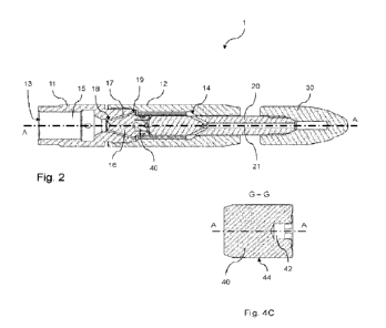
Figure 2 schematically depicts a cross-sectional view onto the nozzle 1 of
figure 1. The
plane of figure 2 is aligned parallel to a longitudinal axis of rotation A-A
of the nozzle head
support shaft 20 inside the housing 11,12. It is visible in figure 2 that the
housing 11,12
comprises a liquid inlet end 13 and a liquid outlet end 14 opposite to the
liquid inlet end 13.
The nozzle 1 further comprises an internal channel 15 running from the liquid
inlet end 13 to
the liquid outlet end 14. During use of the nozzle 1, the liquid inlet end 13
may be connected
to a pressure source, through which a pressurized liquid may be supplied to
the nozzle 1. The
liquid thereby enters the nozzle 1 at the liquid inlet end 13 and flows
through the internal
channel 15 towards the liquid outlet end 14 of the housing 11,12. At the
liquid outlet end 14 of
the housing 11,12, the liquid is then configured to flow into the nozzle head
support shaft 20.
The nozzle head support shaft 20 comprises a liquid channel 21 in fluid
communication
with the internal channel 15 at the liquid outlet end 14. This fluid
communication provides that
the pressurized liquid in the nozzle 1 will flow from the internal channel 15
to the liquid
channel 21 in the nozzle head support shaft 20 during use. The rotary nozzle
head 30 and the
nozzle head support shaft 20 are thereby configured to rotate with respect to
the housing
11,12 about the axis of rotation A-A to provide a rotating spraying of liquid
jetted from the
rotary nozzle head 30.
The nozzle 1 further comprises an axial pressure compensator 16, which is
arranged in
the internal channel 15 and configured to substantially compensate axial
pressure forces from
liquid entering the internal channel 15 at the liquid inlet end 13 of the
housing 11,12. The axial
pressure compensator 16 is, in the present embodiment, an integral part of the
housing 11,12
and comprises a plurality of liquid guiding channels 17 that extend through
the housing 11,12.
Each of the liquid guiding channels 17 comprises an inlet opening 18' that is
in fluid
communication with the liquid inlet end 13 of the housing 11,12 and comprises
an outlet
opening 18" that is in fluid communication with the liquid outlet end 14 of
the housing 11,12
and with the liquid channel 21 of the nozzle head support shaft 20. To allow
liquid to pass
from the liquid inlet end 13 to the nozzle head support shaft 20 during use of
the nozzle 1, the
liquid guiding channels 17 may guide the liquid, while the axial forces
resulting from liquid
pressure of the liquid entering the nozzle 1 at the liquid inlet end 13 are
not transferred to the
nozzle head support shaft 20. In particular, axial pressure forces are
prevented to act onto the
nozzle head support shaft 20 as a result of the liquid flowing from the
internal channel 15 into
the liquid channel 21 of the nozzle head support shaft 20 in a radial inward
direction, see with
respect to the axis of rotation A-A.
The nozzle 1 furthermore comprises an axial bearing seat 40 which is located
within the
first housing part 11 and which is arranged within a blind axial bore of the
axial pressure
CA 03176400 2022- 10- 20
WO 2021/214202 - 14 -
PCT/EP2021/060503
compensator 16 as an insert piece. The axial bearing seat 40 comprises an
axial bearing
surface 41 that faces the respective end surface 22 of the nozzle head support
shaft 20 that
is located in the housing 11,12 and that is located opposite to the end at
which the nozzle
head 30 is attached of the nozzle head support shaft 20.
It is best displayed in the exploded-view representation of figure 3 that the
axial bearing
surface 41 and the support shaft end surface 22, during use, cooperate, e.g.
contact each
other, to form an axial bearing for the nozzle head support shaft 20. This
axial bearing is
configured to prevent the nozzle head support shaft 20 from being displaced
along the
longitudinal axis of rotation A-A.
The axial bearing seat 40 is fluidly connected to the internal channel 15. The
nozzle 1 is
thereby configured to establish a fluid film between the axial bearing surface
41 and the
support shaft end surface 22 to form an axial fluid bearing for the nozzle
head support shaft
20. The liquid may flow in between the axial bearing surface 41 and the
support shaft end
surface 22 during use of the nozzle 1, which implies that the axial bearing
seat 40 and the
nozzle head support shaft 20 are not in direct mechanical contact with each
other, but rather
indirectly via the fluid film.
The nozzle 1 further comprises multiple bleed holes 19 which are arranged in
the
second housing part 12. The bleed holes 19 form a fluid passage through the
walls of the
second housing part 12 and fluidly interconnect the axial bearing seat 40 and
the
surroundings of the nozzle 1. At the bleed holes 19, the liquid may exit the
nozzle 1 and a
bleed flow of liquid may be established towards the surroundings of the nozzle
1. In particular,
at least part of the liquid supplied to the nozzle 1 at the liquid inlet end
13 may flow through
the internal channel 15, via the liquid guiding channels 17 in the axial
pressure compensator
16, back via a slit in between the second housing part 12 and the head end
support shaft 20
towards the axial bearing seat 40 and eventually towards the surroundings of
the nozzle 1 via
the bleed holes 19. A pressure drop may be present at the bleed holes 19,
resulting in a slight
over-pressure at the axial bearing seat 40, compared to an ambient pressure
level. This over-
pressure may force the liquid between the support shaft end surface 22 and the
axial bearing
surface 41 during use of the nozzle 1, in order to contribute in the forming
of the fluid film.
In between the first housing part 11 and the second housing part 12, the
nozzle 1
comprises a first sealing ring 51 and a second sealing ring 52. Both rings
51,52 are
configured to seal-off a seam between the housing parts 11,12 to prevent the
passage of fluid
therein between. The first sealing ring is embodied as a rubber 0-ring 51 and
the second
sealing ring is embodied as a backup-sealing ring 52 made of PTFE. The second
sealing ring
52 may be relatively stiff and may therefore be configured to provide
additional mechanical
stiffness for the 0-ring 51, which is relatively weak by itself.
CA 03176400 2022- 10- 20
WO 2021/214202 - 15 -
PCT/EP2021/060503
Figures 4A ¨ 40 display an embodiment of the axial bearing seat 40 in more
detail. The
axial bearing seat 40 comprises an axial bore 42 in the axial bearing surface
41 that is
aligned concentrically with the axis of rotation A-A. This axial bore 42 is
located centrally in
the axial bearing surface 41 and provides that the support shaft end surface
22 and the axial
bearing seat 40 are not in contact at the central part of the axial bearing
surface 41. Instead,
the contact between the support shaft end surface 22 and the axial bearing
surface 41 is
spread over the remaining part of the axial bearing surface 41 that surrounds
the central axial
bore 42.
The axial bearing surface 41 has a concave shape and the support shaft end
surface
22 has a mating convex shape. The concave axial bearing surface 41 has a
radius of
curvature that is the same as the radius of curvature of the convex support
shaft end surface
22. As such, the axial bearing surface 41 and the support shaft end surface 22
may snugly fit
against each other to provide for an evenly-spread contact between them,
thereby providing,
during use of the nozzle 1, for a fluid film between them with constant
thickness.
Since the axial bearing seat 40 is provided as separate insert piece in the
metallic axial
pressure compensator 16, it may be made of a different material, e.g. other
than a metallic
material. As such, the axial bearing seat 40 comprises a plastic material that
is a fibrous self-
lubricating plastic material. According to the present embodiment, the entire
axial bearing
seat 40 is made of Iglidur0 X, which is a certain type of self-lubricating
plastic material.
The axial bearing seat 40 according to the embodiment in figures 4A ¨ 40
comprises
four grooves 43 in the axial bearing surface 41, which are equally spaced
about the axis of
rotation A-A. These grooves 43 provide a fluid connection between the axial
bore 42 in the
axial bearing seat 40 and the internal channel 15 of the nozzle 1. As such,
the liquid may not
only flow towards an outer contour 44 of the axial bearing seat 40, but may
also flow further
inward towards the axial bore 42. During use of the nozzle 1, the fluid film
may be fed with
fluid along the entire radius R of the axial bearing seat 40, instead of only
at the outer contour
44 of the axial bearing seat 40.
Each of the grooves 43 is aligned in a radial direction R, seen with respect
to the axis of
rotation A-A. Such a radial orientation of the grooves 43 provides that the
length of the
grooves 43, e.g. from the outer contour 44 of the axial bearing seat 40
towards the axial bore
42, is as short as possible.
Furthermore, the grooves 43 comprise a rectangular cross-section. Seen in a
plane
perpendicular to the radial direction R of the axial bearing seat 40, the
grooves 40 thereby
have the shape of a rectangle.
In figures 5A ¨ 5F, various different axial bearing seats are depicted
schematically,
which all comprise a different number of grooves. In figures 5A ¨ 5F, a front
view on the axial
CA 03176400 2022- 10- 20
WO 2021/214202 - 16 -
PCT/EP2021/060503
bearing surface of the respective axial bearing seat is shown on the left and
an isometric view
on the respective axial bearing seat is shown on the right.
Figure 5A shows an axial bearing seat that is free of grooves in its axial
bearing
surface. This axial bearing seat only comprises the axial bore in the axial
bearing surface and
the remaining axial bearing surface has a smooth and annular shape to contact
the nozzle
head support shaft.
Figure 5B shows an axial bearing seat that comprises an axial bore and two
grooves in
fthe axial bearing surface. The grooves are equally spaced at 1800 about the
axis of rotation.
Figure 5C shows an axial bearing seat that comprises an axial bore and three
grooves
in the axial bearing surface. The grooves are equally spaced at 120 about the
axis of
rotation.
Figure 5D shows the axial bearing seat that is also displayed in figures 4A ¨
4C. This
axial bearing seat comprises an axial bore and four grooves in the axial
bearing surface. The
grooves are equally spaced at 90 about the axis of rotation.
Figure 5E shows an axial bearing seat that comprises an axial bore and five
grooves in
the axial bearing surface. The grooves are equally spaced at 72 about the
axis of rotation.
Figure 5F shows an axial bearing seat that comprises an axial bore and six
grooves in
the axial bearing surface. The grooves are equally spaced at 60 about the
axis of rotation.
The axial bearing seats in figures 5A ¨ 5F all comprise grooves that have a
rectangular
cross-section. In figures 5G and 5H, two further different axial bearing seats
are depicted
schematically, which both comprise a different cross-sectional shape of the
grooves. In
figures 5G and 5H, a side view on the respective axial bearing seat is shown
on the left and
an isometric view on the respective axial bearing seat is shown on the right.
Figure 5G thereby shows an axial bearing seat that comprises four grooves that
have a
triangular cross-section.
Figure 5H shows an axial bearing seat that comprises four grooves that have a
cross-
section having the shape of half a circle.
It is understood that other embodiments of the axial bearing seat can be
envisaged,
which for example comprise a different number of grooves with a triangular
cross-section or a
semi-circular cross-section.
The axial bearing seats in figures 5A ¨ 5H all comprise grooves that are
aligned in the
radial direction, seen with respect to the axis of rotation. In figures 51 and
5J, two further
different axial bearing seats are depicted schematically, which both comprise
a different type
of grooves, extending in different directions. In figures 51 and 5J, a side
view on the
respective axial bearing seat is shown on the left, a front view on the axial
bearing surface of
CA 03176400 2022- 10- 20
WO 2021/214202 - 17 -
PCT/EP2021/060503
the respective axial bearing seat is shown in the middle and an isometric view
on the
respective axial bearing seat is shown on the right.
Figure 51 thereby shows an axial bearing seat that comprises four grooves that
have a
rectangular cross-section and that are off-set with respect to the axis of
rotation. The grooves
thereby extend in a direction parallel to a radial direction. However, this
direction does not
intersect with the axis of rotation, but is rather spaced at a distance
therefrom. According to
the embodiment in figure 51, the grooves are aligned in-line with tangential
directions of the
central axial bore in the axial bearing seat.
Figure 5J shows an axial bearing seat that comprises four grooves that have a
rectangular cross-section and that extend spirally away from the central bore.
These grooves
do not extend along a straight line, but rather extend along a curved line to
obtain a spiral
groove pattern.
It is understood that other embodiments of the axial bearing seat can be
envisaged,
which for example comprise a different number of grooves and/or a different
cross-section,
while being aligned off-set with respect to the axis of rotation or being
aligned spirally.
The axial bearing seats in figures 5A ¨ 5J all comprise a concave axial
bearing surface.
In figure 5K, a further different axial bearing seat is depicted
schematically, which comprises
a flat axial bearing surface. In figure 5K, a side view on the respective
axial bearing seat is
shown on the left, a front view on the axial bearing surface of the respective
axial bearing
seat is shown in the middle and an isometric view on the respective axial
bearing seat is
shown on the right.
Figure 5K thereby shows an axial bearing seat that comprises four grooves that
have a
rectangular cross-section. The axial bearing surface has a flat shape, in
order to be
associated with a support shaft end surface that has a mating flat shape. The
flat shape of the
axial bearing surface may provide that the axial bearing surface and the
nozzle head support
shaft may snugly fit against each other to provide for an evenly-spread
contact between them.
It is understood that other embodiments of the axial bearing seat can be
envisaged,
which for example comprise a different number of grooves and/or a different
cross-section
and/or a different direction of extension, while comprising a flat axial
bearing surface.
CA 03176400 2022- 10- 20