Note: Descriptions are shown in the official language in which they were submitted.
IMPLANTABLE ENCAPSULATION DEVICES
FIELD
[0001] The present invention relates to implantable biological devices,
and more
particularly, to implantable encapsulation devices for housing a biological
moiety.
BACKGROUND
[0002] Biological therapies are increasingly viable methods for treating
peripheral
artery disease, aneurysm, heart disease, Alzheimer's and Parkinson's diseases,
autism,
blindness, diabetes, and other pathologies.
[0003] With respect to biological therapies in general, cells, viruses,
viral vectors,
bacteria, proteins, antibodies, and other biological moieties may be
introduced into a
patient by surgical and/or interventional methods that place the biological
moiety into a
tissue bed of a patient. Surgical techniques include blunt planar dissection
into a tissue
or organ. Interventional techniques include injection to a target site via
catheter or
needle. These methods cause trauma to host tissue, leading to inflammation,
lack of
vascularity, and immune reactions, all of which can reduce viability and
efficacy of the
biological moiety. Interventional methods may also reduce the viability and
efficacy of
the biological moiety due to shearing forces experienced during transport
through a fine-
bore needle or catheter. Additionally, increases in pressure caused by the
injection of
the biological moiety into dense tissue can induce trauma to the biological
moiety. As a
result, implanted moieties often do not engraft and may undesirably migrate
from the
injection site.
[0004] In some instances, the biological moiety is protected from the host
immune
system prior to introduction into a body. One way of protecting the biological
moiety is
to encapsulate the moiety prior to introducing the biological moiety into
tissue of a
patient. While the device restricts access to elements of the host's immune
system, it
must also allow for the passage of nutrients and other biomolecules into the
device to
keep the biological moiety viable throughout its life (e.g., loading,
implantation, and
1
Date Regue/Date Received 2022-09-23
explantation). However, there remains many challenges with the effectiveness
of
current encapsulation systems through various stages of its life cycle. One
challenge
includes maintaining survival of the biological moiety during the implantation
and
healing phase where the biological moiety is exposed to a hypoxic environment
with a
limited source of oxygen and nutrients. There are also challenges of
scalability of
designing the encapsulation device for various therapies and dose ranges. One
example is the need to scale various device geometries through pre-clinical
animal
models to a therapeutic dose in humans without changing critical design
dimensions
that would result in a different environment for the biological moiety.
Additionally as the
biological moiety reaches the end of life, there is a desire to extend the
useful life of the
encapsulation device or preserve the surface area in the region of the implant
such that
the area can be re-used for future therapies.
[0005] Therefore, there remains a need for devices that encapsulate cells
and other
biological moieties that are scalable to different sizes, are able to
incorporate various
types of biological moieties and/or sizes of biological moieties, and can be
easily
accessed to remove and/or replace a therapeutic device to allow for leveraging
different
therapies at different stages of the device life or for extending the useful
life of the
device through replacement.
SUMMARY
[0006] One aspect relates to an implantable encapsulation device that
includes a
single containment tube, a first access port located at the first end of the
containment
tube, a second access port located at the second end of the containment tube,
a flush
port fluidly connected to the second access port via a tube, and a cap
releasably
attached to the first end of the containment tube and covering the first
access port. The
flush port may also include a resealable cap. The containment tube may contain
therein
a biological moiety (e.g., cells) or a therapeutic device (e.g. a cell
encapsulation
member).
[0007] A second aspect relates to an implantable encapsulation device that
includes
a containment tube that has a first end and a second end and a single access
port at
one end (e.g., the first end). The other end (e.g., the second end) may simply
be the
2
Date Recue/Date Received 2022-09-23
end of the containment tube or a permanent seal affixed to the second end. The
permanent seal may be a cap non-releasably attached to the second end. The
containment tube may contain therein a biological moiety (e.g., cells) or a
therapeutic
device (e.g. a cell encapsulation member).
[0008] A third aspect relates to an implantable encapsulation device that
includes a
plurality of containment tubes, each containment tube having a first access
port located
at the first end of the containment tube and a second access port located at
the second
end of the containment tube. The first access ports may have thereon
resealable caps
to seal the first end of the containment tubes. The containment tubes may be
interconnected at or near the second ends by connection members. The
containment
tubes are independently movable from each other and are substantially parallel
to each
other along a length of the device. The containment tubes may contain therein
a
biological moiety (e.g., cells) or a therapeutic device (e.g. a cell
encapsulation member).
The encapsulation device may further include a removable manifold having at
least one
access port that is in fluid communication with one or more of the containment
tubes. A
flush port may be fluidly connected to the manifold by a tube.
[0009] A fourth aspect relates to an implantable encapsulation device that
includes a
manifold and a plurality of containment tubes, each containment tube having a
first
access port at a first end and a second access port at a second end. The
containment
tubes are affixed to the manifold at their second ends and are fluidly
connected to the
manifold through the second access ports. The manifold may be located at the
first end
or the second end of the containment tubes. A resealable (or permanent) port
may be
located at the opposing end of the containment tubes. The containment tubes
may be
connected to each other at spaced intervals along their lengths by one or more
connection member and/or may be substantially parallel to one another along a
length
of the containment tubes. The periodically spaced intervals may be regular
(e.g.,
spacing is the same between connection members) or irregular (e.g., the
spacing
between connection members are different). In some embodiments, the
containment
tubes are stacked upon each other in a three dimensional configuration. In yet
other
embodiments, the containment tubes have a substantially planar configuration
with off-
3
Date Regue/Date Received 2022-09-23
axis interconnection members. The containment tubes may contain therein a
biological
moiety (e.g., cells) or a therapeutic device (e.g. a cell encapsulation
member).
[0010] A fifth aspect relates to an implantable encapsulation device that
includes at
least one containment tube having a first end and a second end and a manifold
centrally
located between the first end and the second end. The manifold has at least
one
access port and is fluidly connected to the at least one containment tube. In
some
embodiments, the manifold includes a divider element positioned below the at
least one
access port.
[0011] A sixth aspect relates to an implantable encapsulation device that
includes a
laminate sheet and a plurality of containment channels formed by adhered
layers of the
laminate sheet with seams interposed between each containment channel. The
plurality of containment channels may be periodically connected to each other
via the
seams along a length of the containment channels. It is to be appreciated that
access
ports, manifolds, and/or flush ports may also be included this aspect.
[0012] A seventh aspect relates to an implantable encapsulation device
that includes
a manifold located at the first end or the second end of the encapsulation
device and a
plurality of containment tubes individually affixed to the manifold and in
fluid
communication with the manifold. The plurality of containment tubes may be
interconnected in a non-planar arrangement. In at least one embodiment, the
containment tubes include a shape memory material such that the containment
tubes
are configured to take on the non-planar arrangement.
[0013] An eighth aspect relates to an implantable encapsulation device
that includes
a single containment tube having a first end, a second end, a point located
between the
first end and the second end, a divider element, and a manifold having a
single access
port positioned at the point which is centrally located between the first and
second ends
of the containment tube. The divider element enables the flow of a fluid
containing cells
to be divided such that a portion of the cells flow in a first direction
(e.g., towards the
first end) and a portion of the cells flow in a second direction (e.g.,
towards the second
end). Alternatively, a cell containment member (or other therapeutic device)
may be
placed inside the containment tube though the access port.
4
Date Regue/Date Received 2022-09-23
[0014] A ninth aspect relates to an implantable encapsulation device that
includes a
first containment tube including a first distal end and a first proximal end
having a first
access port and a second containment tube including a second distal end and a
second
proximal end having a second access port, and a manifold fluidly connected to
the first
access port of the first proximal end and to the second access port of the
second
proximal end. The manifold fluidly connects the first and second containment
tubes.
[0015] A tenth aspect relates to an implantable encapsulation device that
includes a
plurality of containment tubes having a first end and a second end, a point
centrally
located between the first end and the second end of the containment tubes, and
a
manifold having multiple access ports. The manifold is in fluid connection
with the
containment tubes. In some embodiments, the manifold includes divider elements
that
enable the flow of a fluid containing cells to be divided such that a portion
of the cells
flow in a first direction (e.g., towards the first end) and a portion of the
cells flow in a
second direction (e.g., towards the second end). It is to be noted that cell
containment
members may be placed inside the containment tubes though the access ports. In
addition, the encapsulation device could be formed of a plurality of first
containment
tubes and second containment tubes connected by the manifold.
BRIEF DESCRIPTION OF THE DRAWINGS
[0016] The accompanying drawings are included to provide a further
understanding
of the disclosure and are incorporated in and constitute a part of this
specification,
illustrate embodiments, and together with the description serve to explain the
principles
of the disclosure.
[0017] FIGS. 1A and 1B are schematic illustrations of cross-sections of a
cell
containment member in accordance with some embodiments;
[0018] FIG. 2 is a schematic illustration of a containment tube in
accordance with
some embodiments;
[0019] FIGS. 3-10 are schematic illustrations of cross-sections of a
porous polymeric
material used to construct a containment tube in accordance with some
embodiments;
[0020] FIG. 11A is a schematic illustration of a containment tube having
two access
ports and a flush port in accordance with some embodiments;
Date Regue/Date Received 2022-09-23
[0021] FIG. 11B is a schematic illustration of a containment tube having a
single
access port in accordance with some embodiments;
[0022] FIG. 12A is a schematic illustration of an encapsulation device
having a
plurality of interconnected containment tubes in accordance with some
embodiments;
[0023] FIG. 12B is a schematic illustration of the encapsulation device of
FIG. 12A
including a flush port and a manifold in accordance with some embodiments;
[0024] FIG. 12C is a schematic illustration of an encapsulation device
having a
plurality of containment tubes and a manifold (with a flush port) located at a
distal end
thereof in accordance with some embodiments;
[0025] FIG. 12D is a schematic illustration of an encapsulation device
having a
plurality of containment tubes and a manifold (with a flush port) located at
both the distal
and proximal ends thereof in accordance with some embodiments;
[0026] FIG. 12E is a schematic illustration of an encapsulation device
that includes a
manifold with a top access port on a first end and a resealable (or permanent)
port on a
second end in accordance with some embodiments;
[0027] FIG. 12F is a schematic illustration of an encapsulation device
that includes a
manifold having a side access port on a first end and a resealable (or
permanent) port
on a second end in accordance with some embodiments;
[0028] FIG. 12G is a schematic illustration of an encapsulation device
that includes a
manifold having a side access port at a first end, a flush port fluidly
connected to the
side access port, and resealable (or permanent) caps at a second end in
accordance
with some embodiments;
[0029] FIG. 12H is a schematic illustration of an encapsulation device
that includes a
manifold having a side access port on a first end and a connection member and
a port
(resealable or permanent) on a second end in accordance with some embodiments;
[0030] FIGS. 13A and B are schematic illustrations of encapsulation
devices
including several individual containment tubes grouped together as a single
unit in
accordance with some embodiments;
[0031] FIGS. 13C and D are photographs depicting containment tubes
connected to
each other at various points along their lengths in accordance with some
embodiments;
6
Date Recue/Date Received 2022-09-23
[0032] FIG. 13E is a schematic illustration of an encapsulation device
with a
resealable port at one end thereof and containment tubes connected to each
other a
various points along their lengths;
[0033] FIG. 13F is a schematic illustration of an encapsulation device
with a manifold
and flush port at one end thereof and containment tubes connected to each
other a
various points along their lengths;
[0034] FIG. 14A is a schematic illustration of an encapsulation device
constructed
from several channels in accordance with some embodiments;
[0035] FIG. 14B is a photograph depicting a containment channels having
seams
between each containment channel in accordance with some embodiments;
[0036] FIGS. 15-17A show various three dimensional arrangements for
encapsulation devices having a plurality of containment tubes in accordance
with some
embodiments;
[0037] FIG. 17B is a photograph of containment tubes having a
substantially planar
arrangement with off-axis interconnection members in accordance with some
embodiments;
[0038] FIG. 17C is a schematic illustration depicting a cell encapsulation
member
having containment tubes fluidly connected by interconnection members;
[0039] FIGS. 18A and 18B is a schematic illustration depicting the
variable
compliance of a resealable port or manifold in accordance with some
embodiments;
[0040] FIG. 19 is a schematic illustration of a cell containment member
containing a
sealing member partially positioned in an opening of a manifold in accordance
with
some embodiments;
[0041] FIG. 20A shows an encapsulation device having a single containment
tube
with a centrally located manifold in accordance with some embodiments;
[0042] FIG. 20B is a schematic illustration of an encapsulation device
having two
containment tubes and a centrally located manifold in accordance with some
embodiments;
[0043] FIG. 21 is a schematic illustration of an encapsulation device
having a
plurality of containment tubes with a centrally located manifold;
7
Date Regue/Date Received 2022-09-23
[0044] FIG. 22 is a schematic illustration depicting cell encapsulation
members being
inserted in an encapsulation device that has been implanted in tissue in
accordance
with some embodiments;
[0045] FIGS. 23-30 are schematic illustrations of encapsulation devices
containing or
having thereon a bio-absorbable material in accordance with some embodiments;
[0046] FIGS. 31A and B are photographs depicting containment tubes
connected by
an access port on one end in accordance with some embodiments;
[0047] FIGS. 32A and B are photographs containment tubes connected by an
access port on both ends in accordance with some embodiments;
[0048] FIG. 33 is a photograph depicting a cell containment device with a
center
manifold in accordance with some embodiments;
[0049] FIG. 34 is a photograph depicting a cell containment device with an
off-center
manifold in accordance with some embodiments;
[0050] FIG. 35 is a photograph depicting an aluminum mold utilized in
Examples 6
and 9 in accordance with some embodiments;
[0051] FIG. 36 is a photograph depicting the cell encapsulation device
formed by the
method described in Example 6 in accordance with some embodiments; and
[0052] FIG. 37 is a photograph of an aluminum template utilized in
Examples 8, 9,
and 10 in accordance with some embodiments.
DETAILED DESCRIPTION
[0053] Persons skilled in the art will readily appreciate that various
aspects of the
present disclosure can be realized by any number of methods and apparatus
configured
to perform the intended functions. It should also be noted that the
accompanying
figures referred to herein are not necessarily drawn to scale, and may be
exaggerated
to illustrate various aspects of the present disclosure, and in that regard,
the figures
should not be construed as limiting. Also, it is to be noted that the terms
"containment
tube" and "cell containment tube" are used interchangeably herein. In
addition, the
terms "porous polymeric membrane" and "polymeric membrane" are used
interchangeably herein. It is also to be appreciated that the term
"therapeutic device"
may be used interchangeably with term "cell containment member" herein.
8
Date Regue/Date Received 2022-09-23
[0054] The present disclosure relates to implantable encapsulation devices
that
contain at least one containment tube capable of containing therein a
biological moiety
or a therapeutic device containing a biological moiety. Therapeutic devices
may include
a cell encapsulation device, a drug delivery device, or a gene therapy device.
Biological
moieties suitable for encapsulation and implantation using the devices
described herein
include cells, viruses, viral vectors, gene therapies, bacteria, proteins,
polysaccharides,
antibodies, and other bioactive moieties. For simplicity, herein the
biological moiety is
referred to as a cell or cells, but nothing in this description limits the
biological moiety to
cells or to any particular type of cell, and the following description applies
also to
biological moieties that are not cells.
[0055] The encapsulation devices include one or a plurality of containment
tubes. In
encapsulation devices having one containment tube, the encapsulation device
may
include the single containment tube, an access port at both the proximal and
distal end
of the containment tube, a flush port fluidly connected to the access port at
the distal
end, and a resealable (or permanent) cap attached to the proximal end of the
containment tube. The flush port may also include a resealable cap. Although
resealable caps are described herein as a means to close off and/or seal the
access
ports, any resealable device (e.g., permanent caps or welded seals) may be
used to
close and/or seal the access ports. Also, the term "access port" as used
herein is
meant to include any opening into the containment tube for the introduction
and/or
extraction of fluids, biologic moieties, and/or therapeutic devices.
[0056] In encapsulation devices having multiple containment tubes, the
device may
include a plurality of interconnected containment tubes substantially parallel
to each
other along a length of the device. As used herein, the term "substantially
parallel" is
meant to describe containment tubes that extend in the same direction and do
not
intersect each other. In another embodiment, the containment tubes intersect
at least
once and are independently movable. The containment tubes have an access port
at
the proximal end. It is to be appreciated that the terms "proximal end" and
"distal end"
as used herein with respect to members of the device are used for convenience
to
describe the device, and are exemplary in nature. For instance, a member
described as
being on the proximal end of the device may equally be employed at the distal
end. In
9
Date Recue/Date Received 2022-09-23
some embodiments, the containment tubes are formed of multiple layers that
balance
and enhance the hoop and tensile strength of the individual tubes. In another
embodiment, the tubes are formed from a laminate material in which strength is
derived,
at least in part, to the materials forming the laminate. In at least one
embodiment, the
containment tubes are independently movable from each other, thus making the
device
flexible and/or compliant with tissue and/or tissue movement. In addition the
periodic
separation of the tubes can allow for tissue ingrowth around the tubes through
the
periodic tube separations, thereby improving effective device surface area for
vascularization and nutrient and biomolecule exchange. The containment tubes
maximize surface area available for vascularization relative to the device
footprint in the
body. For instance, the containment tubes take advantage of the z-direction
without
making the footprint larger. Additionally, there is no significant non-usable
surface are
due to perimeter or distal seals. In some embodiments, the containment tubes
are
configured to house at least one therapeutic device that provides therapeutic
substances to an individual in need of treatment. In other embodiments, the
containment tubes are configured to house the cells directly (i.e., with no
therapeutic
device). In some embodiments, the cells may be microencapsulated. For
instance, the
cells may be microencapsulated within a biomaterial of natural or synthetic
origin,
including, but not limited to, a hydrogel biomaterial. Additionally, the
containment tubes
may be fluidly connected so that insertion of cells into one containment tube
may flow
into another containment tube or so that a fluid stream may be used to remove
a
therapeutic device from a containment tube. In other embodiments, the
containment
tubes may be stacked three dimensionally or have a substantially planar
arrangement
with off-axis interconnection members.
[0057] The encapsulation device may also include a removable or non-
removable
(e.g., permanent) manifold attached at one or both ends of the containment
tubes. It is
to be noted that with respect to the manifolds, caps, and seals described
herein may be
removable or non-removable, depending on the particular situation. In some
embodiments, a flush port is fluidly connected to the manifold via a tube. The
tube may
have a length that is substantially the length of the containment tube. Fluid
can be
introduced into the distal ends of the containment tubes via the flush port
and manifold
Date Regue/Date Received 2022-09-23
to assist in the discharge or removal of the one or more therapeutic devices
from the
proximal ends of the containment tubes. In another embodiment the
encapsulation
device includes a single or a plurality of containment tubes and a manifold
positioned at
a point between the distal end and the proximal end of the containment tube(s)
(e.g.,
center or off center by a predetermined distance). The manifold optionally
includes a
divider element that directs the therapeutic device(s) or cells toward the
distal end
and/or the proximal end of the containment tube. The containment tube(s) may
be
configured to house one or more therapeutic device that provide therapeutic
substances. In other embodiments, the containment tube(s) are configured to
house the
cells directly.
[0058] Encapsulation devices described herein may be implanted into a
patient prior
to or after insertion of a therapeutic device or cells into one or more of the
containment
tubes. For example, an encapsulation device may be inserted into a patient and
allowed to vascularize such that vascular tissue grows into a vascularizing
layer of the
containment tube. Then, the cells or therapeutic device may be added to the
containment tube in vivo. Alternatively, a therapeutic device or cells may be
placed
within the containment tubes prior to insertion of the encapsulation device
into a tissue
bed of a patient. The encapsulation devices described herein are also capable
of
explantation or removal from the patient such as if the patient goes into
remission and
no longer needs the device or the device needs to be taken out for other
reasons such
as a severe immunologic response. In such a case, a new encapsulation device
may
be implanted
I. Cell Containment Member
[0059] In some embodiments, a therapeutic device, such as a cell
containment
member, is implemented for providing therapeutic substances to an individual
in need of
treatment. It is to be appreciated that the term "therapeutic device" may be
used
interchangeably with term "cell containment member" herein. The cell
containment
member is structured such that it maximizes a proportion of cells in close
proximity to a
permeable membrane that is in contact with the environment while maintaining a
geometry that is practical for implantation in a patient. As shown in FIGS. 1A
and 1B,
this may be accomplished by providing a cell containment member 100 that
includes a
11
Date Regue/Date Received 2022-09-23
core 105 that is surrounded by a permeable membrane 110. The space between the
outer surface of the core 105 and the inner surface of the permeable membrane
110
define a boundary zone in which cells 115 may be contained. In some
embodiments,
the cells may be microencapsulated. The cells may be microencapsulated within
a
biomaterial of natural or synthetic origin, including, but not limited to, a
hydrogel
biomaterial. A maximum distance between the outer surface of the core 105 and
the
inner surface of the permeable membrane 110 is sufficiently narrow to provide
conditions suitable for the survival and function of the contained cells 115,
whereby the
viability of a large proportion of the contained cells 115 is maintained. In
particular, the
cells 115 contained within the cell containment member 100 are able to obtain
nutrients
and other biomolecules from the environment outside the cell containment
member 100
and expel waste products and therapeutic substances outside the cell
containment
member 100 through the permeable membrane 110. Suitable distances to ensure
cell
survival may include from about 30 microns to about 1,000 microns, from about
40
microns to about 900 microns, from about 50 microns to about 800 microns, or
from
about 40 microns to about 700 microns.
[0060] Any material which acts to displace cells from the center of the
cell
containment member 100 is suitable for use as the material of the core 105.
For
example, suitable core materials include, but are not limited to,
polytetrafluoroethylene
(PTFE), expanded polytetrafluoroethylene (ePTFE), polydimethysiloxane,
polyurethane,
polyester, polyamide, or hydrogels derived from polysaccharides, alginate,
hydrolyzed
polyacrylonitrile, and combinations thereof. In some embodiments, the core is
a flexible
polymer or elastomer. In other embodiments, the core may be manufactured from
polysaccharides, hydrophilic copolymers of polyacrylonitrile, a copolymer of
polyacrylonitrile and acrylamide, and/ or other non-porous polymers.
[0061] The permeable membrane may be manufactured from any biologically
compatible material having the appropriate permeability characteristics. The
permeable
membrane has permeability characteristics that permit the passage therethrough
of
cellular nutrients, biomolecules, waste products, and therapeutic substances
secreted
by cells contained within the device while not permitting the passage of cells
external to
the cell encapsulation device. Non-limiting examples of polymers having
suitable
12
Date Regue/Date Received 2022-09-23
selective permeability and/or porous properties and which may be used as the
permeable membrane include, but are not limited to, alginate, cellulose
acetate,
polyalkylene glycols such as polyethylene glycol and polypropylene glycol,
panvinyl
polymers such as polyvinyl alcohol, chitosan, polyacrylates such as
polyhydroxyethylmethacrylate, agarose, hydrolyzed polyacrylonitrile
polyacrylonitrile
copolymers, polyvinyl acrylates such as polyethylene-co-acrylic acid, porous
polytetrafluoroethylene (PTFE), modified polytetrafluoroethylene polymers,
tetrafluoroethylene (TEE) copolymers, porous polyalkylenes such as porous
polypropylene and porous polyethylene, porous polyvinylidene fluoride, porous
polyester sulfone (PES), porous polyurethanes, porous polyesters, porous PPX
(ePPX),
porous ultra-high molecular weight polyethylene (eUHMWPE), porous ethylene
tetrafluoroethylene (eETFE), porous vinylidene fluoride (eVDF), porous
polylactic acid
(ePLLA), and copolymers and combinations thereof, as well as woven or non-
woven
collections of fibers or yarns, or fibrous matrices, either alone or in
combination.
[0062] Various types of prokaryotic and eukaryotic cells, mammalian cells,
non-
mammalian cells, and stem cells may be used with the cell containment members
and
containment tubes described herein. In some embodiments, the cells may be
microencapsulated within a biomaterial of natural or synthetic origin,
including, but not
limited to, a hydrogel biomaterial. In some embodiments, the cells secrete a
therapeutically useful substance. Such therapeutically useful substances
include
hormones, growth factors, trophic factors, neurotransmitters, lymphokines,
antibodies or
other cell products which provide a therapeutic benefit to the device
recipient.
Examples of such therapeutic cell products include, but are not limited to,
insulin,
growth factors, interleukins, parathyroid hormone, erythropoietin,
transferrin, and Factor
VIII. Non-limiting examples of suitable growth factors include vascular
endothelial
growth factor, platelet-derived growth factor, platelet-activating factor,
transforming
growth factors bone morphogenetic protein, activin, inhibin, fibroblast growth
factors,
granulocyte-colony stimulating factor, granulocyte-macrophage colony
stimulating
factor, glial cell line-derived neurotrophic factor, growth differentiation
factor-9,
epidermal growth factor, and combinations thereof.
13
Date Regue/Date Received 2022-09-23
Containment Tubes
[0063] FIG. 2 shows an exemplary implantable containment tube 200 that
includes a
first access port 215, a second access port 225, a permeable membrane 205
forming
the exterior of the containment tube 200, and a lumen 210 extending through
the
containment tube 200. In some embodiments, the containment tube 200 is a
flexible
tube that is configured to receive one or more therapeutic device that
provides
therapeutic substances to an individual in need of treatment. In accordance
with some
aspects of the present disclosure, the containment tube 200 has a cross-
section in a
shape that conforms or substantially conforms, at least in part, to the form
of the
therapeutic device (e.g., cell containment member) the containment tube 200 is
intended to house. As non-limiting examples, the cross-section of the
containment tube
200 may be circular, ovoid, or elliptical. In the embodiments disclosed
herein, the
containment tubes may have inner diameters that range from about 100 microns
to
about 5 mm, from about 150 microns to about 4.5 mm, from about 200 microns to
about
4 mm, or from about 250 microns to about 3.5 mm. In some embodiments in which
multiple containment tubes are utilized, the containment tubes may be
separated from
each other a distance from about 0.1 microns to about 3 mm, from about 5
microns to
about 2.5 mm, from about 10 microns to about 2 mm, from about 25 microns to
about
1.5 mm, or from about 50 microns to about 1 mm. It is to be noted that all
ranges
described herein are exemplary in nature and include any and all values in
between.
[0064] In some embodiments, the containment tube 200 is a flexible tube
configured
to receive cells directly (e.g., without the presence of a therapeutic
device). The
containment tube 200 is structured such that it maximizes the number of cells
in close
proximity to the permeable membrane 205 that is in contact with the
environment while
maintaining a geometry which is practical for implantation in a patient. The
lumen 210
defines an area in which cells may be contained. In addition, the lumen 210
provides
conditions that are suitable for survival and function of the contained cells.
Suitable
distances to ensure cell survival may include from about 30 microns to about
1,000
microns, from about 40 microns to about 900 microns, from about 50 microns to
about
800 microns, or from about 40 microns to about 700 microns. For example, the
cells
contained within the lumen 210 of the containment tube 200 are able to obtain
nutrients
14
Date Regue/Date Received 2022-09-23
and other biomolecules from the environment outside the containment tube 200
and
expel waste products and therapeutic substances outside the containment tube
200
through the permeable membrane 205.
[0065] The containment tube 200 is scalable in that it can easily be
configured
throughout a range of diameters so that the containment tube can be used to
house
cells and/or therapeutic devices with varying shapes and sizes while ensuring
survival
and function of these cells. To ensure that conditions are suitable for the
survival and
function of the cells contained within the containment tube 200, the diameter
of the
containment tube 200 is either sufficiently small such that nutrients and
other
biomolecules are able to reach the center of the tube 200 or a central portion
of the
containment tube 200 contains a cell displacing member so that a maximum
distance
between the displacing member and the wall of the containment tube 200 is such
that
the viability of a large portion of the cells is maintained. In some
embodiments, cells are
introduced into the containment tube 200 in the form of a suspension or slurry
in a
medium. The cells may be individual cells, cell aggregates, or cell clusters.
As one
example, the medium may be a cell culture or cell growth medium, optionally
including
desired nutrients and other biomolecules. In some embodiments, insertion of
the cells
into the containment tube may be accomplished using a syringe.
[0066] In some embodiments, the permeable membrane 205 of the containment
tube 200 is made of a porous polymeric material having selective sieving
and/or porous
properties. The porous polymeric material controls the passage of solutes,
biochemical
substances, viruses, and cells, for example, through the material, primarily
on the basis
of size. Porous polymeric materials having suitable selective permeability
and/or
porous properties useful for construction of containment tubes as described
herein
include, but are not limited to, alginate, cellulose acetate, polyalkylene
glycols such as
polyethylene glycol and polypropylene glycol, panvinyl polymers such as
polyvinyl
alcohol, chitosan, polyacrylates such as polyhydroxyethylmethacrylate,
agarose,
hydrolyzed polyacrylonitrile, polyacrylonitrile copolymers, polyvinyl
acrylates such as
polyethylene-co-acrylic acid, porous polytetrafluoroethylene (PTFE), modified
polytetrafluoroethylene polymers, tetrafluoroethylene (TFE) copolymers, porous
polyalkylenes such as porous polypropylene and porous polyethylene, porous
Date Regue/Date Received 2022-09-23
polyvinylidene fluoride, porous polyester sulfone (PES), porous polyurethanes,
porous
polyesters, and copolymers and combinations thereof. In other embodiments, the
materials useful as an outer porous layer include biomaterial textiles.
[0067] In some embodiments, the porous polymeric material may be a bio-
absorbable material. Alternatively, the porous polymeric material may be
coated with a
bio-absorbable material or a bio-absorbable material may be incorporated into
or onto
the porous polymeric material in the form of a powder. Coated materials may
promote
infection site reduction, vascularization, and favorable type 1 collagen
deposition. The
porous polymeric materials described herein may include any bio-absorbable
material
known in the art. Non-limiting examples include, but are not limited to,
polyglycolide:trimethylene carbonate (PGA:TMC), polyalphahydroxy acid such as
polylactic acid, polyglycolic acid, poly (glycolide), and poly(lactide-co-
caprolactone),
poly(caprolactone), poly(carbonates), poly(dioxanone), poly
(hydroxybutyrates),
poly(hydroxyvalerates), poly (hydroxybutyrates-co-valerates), and copolymers
and
blends thereof.
[0068] In some embodiments, the bio-absorbable material may have the
capability to
generate reactive oxygen species (ROS) at different levels in the body. ROS
have been
shown to promote various cell responses in the body, including, but not
limited to,
inhibiting or promoting cell proliferation, differentiation, migration,
apoptosis, and
angiogenesis. ROS generating materials can be made according to the teachings
set
forth in, for example, U.S. Patent No. 9,259,435 to Brown, et al.
[0069] In embodiments where the permeable membrane 205 is porous only
through
a portion of its thickness, the molecular weight cutoff, or sieving property,
of the porous
membrane 205 begins at the surface. As a result, certain solutes and/or cells
do not
enter and pass through the porous spaces of the material from one side to the
other.
FIG. 3 shows a cross-sectional view of a porous polymeric material 300 useful
in a
containment tube described herein, where the selective permeability of the
polymeric
material 300 excludes cells 305 from migrating or growing into the porous
spaces of the
polymeric material 300 while permitting bi-directional flux of solutes 310
across the
thickness of the polymeric material 300. Vascular endothelial cells can
combine to form
capillaries thereon. Such capillary formation or neovascularization of the
polymeric
16
Date Regue/Date Received 2022-09-23
material 300 of the containment tube permits fluid and solute flux between
tissues of a
patient and the contents of a therapeutic device to be enhanced.
[0070] In some embodiments, permeability of the polymeric material can be
varied
continuously across the thickness of the polymeric material. FIG. 4 is a cross-
sectional
view of a porous polymeric material 400 useful in a containment tube described
herein,
where the selective permeability of the polymeric material 400 varies
continuously
across the thickness of the material as indicated by the gradually increasing
density of
the stippling in the figure. In some embodiments, the permeability of the
porous
polymeric material 400 is varied from one cross-sectional area of the material
to another
to form a stratified structure. FIG. 5 is a cross-sectional view of a
polymeric material
500 useful in a containment tube described herein, where the selective
permeability of
the polymeric material 500 varies across the thickness of the polymeric
material 500 as
indicated by the increasing density of the stippling in the figure.
[0071] In some embodiments, the permeability of the porous polymeric
material is
varied across its thickness with additional layers of porous polymeric
material. FIG. 6 is
a cross-sectional view of a porous polymeric material 600 useful in a
containment tube
described herein, where the selective permeability of the polymeric material
600 is
varied across the thickness of the polymeric material 600 with one or more
additional
layers of porous polymeric material 605. The additional layers of porous
polymeric
material 605 may have the same composition and permeability as the initial
layer of
porous polymeric material 600 or the one or more additional layers 605 may
have a
different composition and/or permeability.
[0072] In another embodiment, the selective permeability of the porous
polymeric
material is varied by impregnating the void spaces of the porous polymeric
material with
a hydrogel material. A hydrogel material can be impregnated in all or
substantially all of
the void spaces of a porous polymeric material (e.g., pores of a porous
membrane) or in
only a portion of the void spaces. For example, by impregnating a porous
polymeric
material with a hydrogel material in a continuous band within the polymeric
material
adjacent to and/or along the interior surface of the porous polymeric
material, the
selective permeability of the porous polymeric material is varied from an
outer cross-
sectional area of the porous polymeric material to an inner cross-sectional
area of the
17
Date Regue/Date Received 2022-09-23
porous polymeric material. FIG. 7 is a cross-sectional view of a porous
polymeric
material 700 useful in a containment tube described herein, where the
selective
permeability of the polymeric material 700 is varied across the thickness 705
of the
polymeric material 700 with a hydrogel material 710.
[0073] The amount and composition of hydrogel material impregnated into
the
porous polymeric material depends in large part on the particular porous
polymeric
material used to construct an apparatus, the degree of permeability required
for a given
application, and the biocompatibility of the hydrogel material. Non-limiting
examples of
useful hydrogel materials for use in the present invention include, but are
not limited to,
hydrolyzed polyacrylonitrile, alginate, agarose, carrageenan, collagen,
gelatin, polyvinyl
alcohol, poly(2-hydroxyethyl methacrylate), poly(N-vinyl-2-pyrrolidone),
polyethylene
glycol, polyethyleneimine, fibrin-thrombin gels, or gellan gum, and copolymers
thereof,
either alone or in combination. In certain aspects of the present invention,
the total
thickness of an expanded PTFE/hydrogel composite may range from about 2 pm to
about 1000 pm.
[0074] In yet other embodiments, the permeability of the porous polymeric
material
can be varied across the thickness of the polymeric material with an
additional layer of
porous polymeric material and a further layer of hydrogel material. FIG. 8 is
a cross-
sectional view of a porous polymeric material 800 useful in a containment tube
described herein, where the selective permeability of the polymeric material
800 is
varied across the thickness 805 of the polymeric material 800 with an
additional layer of
porous polymeric material 810 and a further layer of a hydrogel material 815.
An
advantage of this embodiment is the additional protection provided an implant
patient
against contamination with cells from a failed containment tube or cell
containment
member described herein. In addition, this configuration will provide a strong
cell and
humoral immunoisolation barrier.
[0075] In some embodiments, the permeability of the porous polymeric
material is
selected to permit growth of cells from a patient into, but not through, the
polymeric
material. In one or more embodiment, a cell permeable zone is formed in the
void
spaces of a porous polymeric material starting at the exterior surface of the
polymeric
material and continuing to a point within the polymeric material adjacent to
the interior
18
Date Regue/Date Received 2022-09-23
surface of the cell containment tube where the permeability of the porous
polymeric
material to cells is decreased so that cells that have migrated into the void
spaces of the
polymeric material cannot migrate further and penetrate the interior surface
of the
polymeric material. FIG. 9 depicts a cross-sectional view of a porous
polymeric material
900 useful in a containment tube described herein, where the polymeric
material 900
includes a cell permeable zone 905 beginning at the exterior surface 910 of
the
polymeric material 900 and continuing across the thickness of the polymeric
material
900 to a cell exclusion zone 915 within the polymeric material 900 adjacent to
and
continuous with the interior surface 920 of the polymeric material 900.
[0076] The region of the porous polymeric material in which cells cannot
migrate or
grow is referred to as a cell exclusion zone and is impervious to cellular
ingrowth. A cell
exclusion zone prevents or minimizes invasive cells from entering the lumen of
the
containment tube and contacting, adhering to, fouling, ingrowing, overgrowing,
or
otherwise interfering with a therapeutic device or cells contained within the
containment
tube. To exclude invading host cells from growing through to the interior
surface of the
containment tube, the pore size of the cell exclusion zone may be less than
about 5
microns, less than about 1 micron, or less than about 0.5 microns, as measured
by
porometry. In some embodiments, the permeability of the polymeric material may
be
adjusted with a hydrogel material.
[0077] In some embodiments, the permeable membrane is a composite material
or
laminate that includes an outer porous polymeric layer and an inner porous
polymeric
layer disposed adjacent to the outer porous polymeric layer. The inner and
outer
porous polymeric layers have different porosities, and may include or be
formed of the
same material or different materials. In some embodiments, the inner porous
layer has
a porosity that is less than the porosity of the outer porous layer. Portions
of the inner
porous polymeric layer form the interior surface of the containment tube.
[0078] The inner porous polymeric layer is impervious to cellular or
vascular
ingrowth, and is sometimes referred to as a cell retentive layer or a tight
layer. In some
embodiments, the inner porous layer has an average pore size that is less than
about 5
microns, less than about 1 micron, or less than about 0.5 microns, as measured
by
19
Date Regue/Date Received 2022-09-23
porometry. In some embodiments, the pores resist cellular ingrowth but are
selectively
permeable to macromolecules.
[0079] The outer porous layer has an average pore size that is large
enough to
permit growth of vascular tissue from a patient into the pores of the outer
porous
polymeric layer. This layer may be referred to as a vascularizing or an open
layer. In
some embodiments, the pore size of the outer porous polymeric layer is greater
than
about 5.0 microns, as measured by porometry. Ingrowth of vascular tissues
through the
outer porous layer facilitates nutrient and other biomolecule transfer from
the body to
the cells encapsulated in the containment tube.
[0080] Optionally, the containment tube may include only the outer porous
polymeric
material, or a laminate formed of multiple porous polymeric materials, where
each
porous polymeric material has sufficient porosity to permit growth of vascular
tissue
from a patient into the pores of the polymeric material. As such, growth of
vascular
tissue is permitted through the entire thickness of the polymeric material(s)
forming the
containment tube.
[0081] Various cell types can grow into the cell permeable zone
vascularizing (open)
layer of a porous polymeric material of a containment tube as described
herein. The
predominant cell type that grows into a particular porous polymeric material
depends
primarily on the implantation site, the composition and permeability of the
material, and
any biological factors, such as cytokines and/or cell adhesion molecules, for
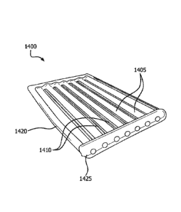
example,
that may be incorporated in the material or introduced through the containment
tube. In
some embodiments, vascular endothelium is the predominant cell type that grows
into a
porous polymeric material for use in a containment tube. Vascularization of
the porous
polymeric material by a well-established population of vascular endothelial
cells in the
form of a capillary network is encouraged to occur as a result of
neovascularization of
the material from tissues of a patient into and across the thickness of the
material very
close to the interior surface of the apparatus, but not across the cell
exclusion zone or
cell retentive (or tight) layer.
[0082] FIG. 10 is a cross-sectional view of a porous polymeric material
1000 useful
in a containment tube described herein, where the polymeric material 1000
includes a
cell permeable zone 1005 beginning at the exterior surface 1010 of the
polymeric
Date Regue/Date Received 2022-09-23
material 1000 and continuing across the thickness of the polymeric material
1000 to a
cell exclusion zone 1015 within the polymeric material 1000 adjacent to and
continuous
with the interior surface 1020 of the polymeric material 1000. The cell
permeable zone
1005 is populated with vascular structures 1025. Vascularization can occur
without the
addition of biological factors and/or, angiogenic factors, which can be used
to enhance
vascularization of the containment tube. In addition, angiogenesis can be
stimulated by
conditions, such as hypoxia. The neovascularization of a containment tube
improves
mass transport of therapeutic drugs or biochemical substances between the
interior
surface of the containment tube and tissues of a patient, thereby enhancing
the quantity
and rate of transport of therapeutic drugs or biochemical substances between
the
contents of a therapeutic device housed in the containment tube and tissues of
the
patient.
[0083] In some embodiments, the encapsulation device is implanted into a
patient in
a configuration similar to or dissimilar to its final configuration, but for
the encapsulation
device to assume its final shape, some migration of the implanted
encapsulation device
may occur. Vascularization and other tissue ingrowth of the cell permeable
zones of the
containment tubes as described herein can anchor the encapsulation device at
the
implantation site. This anchoring, however, does not prevent the
transformation of the
encapsulation device into its primary shape because shape changes of the
device occur
shortly after implantation and before significant vascularization and other
tissue growth
occurs. The shape transformation may be a result of significant forces exerted
by a
shape memory element or by the manifold joining the ends of the containment
tubes.
The anchoring minimizes or prevents the encapsulation device from moving from
the
implantation site over time and once sufficient anchoring has occurred, can
assist the
encapsulation device in maintaining its shape. Maintaining the shape of a
containment
tube as described herein is often necessary for easy placement, replacement,
and
proper functioning of the cells contain contained in the cell containment
tube(s) within
the encapsulation device.
[0084] In some embodiments, the containment tube includes a shaping
element.
The shaping element can be configured to induce the containment tube into a
more
compliant structure such as a curved or wavy shape, such as a generally
toroidal
21
Date Recue/Date Received 2022-09-23
configuration, in a tissue bed. In some embodiments, the shaping element may
also
hold the containment tube in a desired shape during implantation and
subsequent use.
Non-limiting examples of useful shaping elements include windings, strips,
spline,
stents, and combinations thereof. The shaping elements may be on the exterior
surface
of the conduit of the containment tube, between the layers of the conduit or
along the
interior surface of the conduit. In one embodiment, the shaping element
provides the
ability to insert the containment tube in any configuration convenient for
insertion, and
once inserted the containment tube independently assumes a preferred in-use
configuration. In another embodiment, a shaping element holds the containment
tube in
a preferred configuration in use such that therapeutic devices can easily be
removed
from and inserted into the containment tube.
[0085] In some embodiments, the shaping element includes a shape memory
material or structure made therefrom. Non-limiting examples of useful shape
memory
materials include shape memory alloys, such as nitinol, and shape memory
polymers
such as polyetheretherketone, polymethyl methacrylate, polyethyl methacrylate,
polyacrylate, poly-alpha-hydroxy acids, polycaprolactones, polydioxanones,
polyesters,
polyglycolic acid, polyglycols, polylactides, polyorthoesters, polyphosphates,
polyoxaesters, polyphosphoesters, polyphosphonates, polysaccharides,
polytyrosine
carbonates, polyurethanes, polyurethanes with ionic or mesogenic components
made
by a pre-polymer method, and copolymers or polymer blends thereof. Other block
copolymers also show the shape-memory effect, such as, for example, a block
copolymer of polyethylene terephthalate (PET) and polyethyleneoxide (PEO),
block
copolymers containing polystyrene and poly(1,4-butadiene), and an ABA triblock
copolymer made from poly(2-methyl-2-oxazoline) and polytetrahydrofuran. Non-
limiting
shape memory alloys include, but are not limited to, copper-aluminum-nickel,
copper-
zinc-aluminum, and iron- manganese-silicon alloys. In addition to inducing the
containment tube into a desired (pre-determined) configuration in use, the
shape
memory element facilitates implantation, including facilitating any change in
profile of
the containment tube during implantation.
[0086] Many of the materials used to construct a containment tube as
described
herein are inherently radio-opaque. Those materials that are not inherently
radio-
22
Date Recue/Date Received 2022-09-23
opaque can be modified to be radio-opaque by impregnation of the material with
barium, for example. Other useful methods for rendering a material radio-
opaque are
known to those skilled in the art. The radio-opacity of materials used to
construct a
containment tube as described herein is mainly used to facilitate surgical
placement of
the containment tube or to locate the containment tube in a patient following
implantation.
[0087] In some embodiments, a containment tube as described herein
maintains a
consistent cylindrical cross-section for containing cells or a generally
cylindrically
shaped therapeutic device (e.g., a cell containment member). In some tubular
embodiments, open ends of the tube can be prevented from collapsing with a
stent.
The stent can be in any shape and made of any biocompatible material useful
for
keeping all or part of tubular containment tube in an opened, or expanded,
tubular form
during storage and/or following implantation. Useful materials for a stent
include, but
are not limited to, stainless steel, titanium, and hydrogels. To maintain the
containment
tube in an expanded configuration when a therapeutic device (e.g., cell
containment
member) is not inserted or no cells are present, an inert core simulating the
shape and
resilience of a therapeutic device may be placed in the containment tube. A
cell
encapsulation device as described herein may be implanted into a patient prior
to or
after insertion of a therapeutic device or cells into one or more of the
containment tubes.
For example, an encapsulation device may be inserted into a patient and
allowed to
vascularize such that vascular tissue grows into a vascularizing layer of the
cell
containment tube. The cells or therapeutic device may then be added to the
containment tubes in vivo. Alternatively, a therapeutic device or cells may be
placed
within the containment tubes prior to insertion of the encapsulation device
into a tissue
bed of a patient.
III. Encapsulation Device With One Containment Tube
[0088] FIG. 11A depicts an encapsulation device 1100 containing a single
containment tube 1105 in accordance with at least one embodiment. The
encapsulation
device 1100 may include a containment tube 1105, a first access port 1150 at a
proximal end 1115, a second access port 1140 at a distal end 1110, a flush
port 1120
fluidly connected to the second access port 1140 port via a tube 1135 and a
connection
23
Date Regue/Date Received 2022-09-23
member 1130. A resealable cap 1125 may be attached to the proximal end 1115 of
the
containment tube 1105. The flush port 1120 may also include a resealable cap
1160.
Although resealable caps are described herein as a means to close off and/or
seal the
access ports, any resealable device may be used. In alternative embodiments,
the
encapsulation device 1100 may have a resealable cap 1125 at the distal end
1110 and
a connection member 1130 at the proximal end 1115 (not illustrated). In other
embodiments, the encapsulation device 1100 may have a resealable cap 1125 at
both
the proximal end 1115 and the distal end 1110 (not illustrated). In yet other
embodiments, the encapsulation device 1100 has a flush port 1120 at both the
proximal
end 1115 and the distal end 1110 (not illustrated).
[0089] The second access port 1150 provides an access point through which
cells
and/or one or more therapeutic device may be moved in and out of the luminal
region of
the containment tube 1105. The flush port 1120 provides an access point
through
which a fluid stream can be delivered to the luminal region of the containment
tube 1105
to fill and/or flush the luminal region of the containment tube 1105. In some
embodiments, the fluid stream can be used to fill the luminal region with
cells. In other
embodiments, the fluid stream can be used to push the one or more therapeutic
devices
or cells from the luminal region of the containment tube 1105 through the
second
access port 1150 to an area external to the containment tube 1105.
[0090] As discussed above, the flush port 1120 is in fluid communication
with the
containment tube 1105 via the tube 1135. In some embodiments, the tube 1135 is
constructed of a biocompatible material having a length that is substantially
equal, such
as within 1 cm, to a length of the containment tube 1105 such that a proximal
end of the
tube 1135 with the resealable cap 1160 resides near or adjacent to the
proximal end
1115 of the containment tube 1105 (and/or near to the proximal end of the
encapsulation device 1100) when the encapsulation device 1100 is implanted in
a
patient. In embodiments in which the encapsulation device 1100 has a flush
port at
both the proximal end 1115 and the distal end 1110 of the containment tube
1105, the
access port on either the proximal end or the distal end of the containment
tube can be
used to provide an access point through which cells and/or one or more
therapeutic
device may be moved in and out of the luminal region of the containment tube
(not
24
Date Regue/Date Received 2022-09-23
illustrated). The containment tube 1105 may be constructed with a composite
material
having a cell retention layer and vascularizing layer as described herein.
[0091] The resealable caps 1125, 1160 and the connection fitting 1130 are
secured
to the porous polymeric material forming the containment tube 1105.
Commercially
available fittings, such as Luer-lok connectors can also be used as a
resealable cap
1125, 1160. In some embodiments, one or more of resealable caps 1125,1160
and/or
connection fitting 1130 is a hollow cylindrically shaped fitting having a
first portion that
fits snugly inside an end of the containment tube 1105 and a second portion
that
extends beyond the end of the containment tube 1105 to receive and retain a
sealing
element. In some embodiments, the resealable caps 1125,1160 and connection
fitting
1130 may be fabricated by injection molding a fitting onto the end of the
containment
tube 1105 using techniques known to those skilled in the art. In some
embodiments,
the resealable cap 1125 is a hole in the containment tube 1105 with one or
more flexible
pieces, or flaps, of porous polymeric material positioned to cover and close
the hole.
The flaps may be formed as part of the encapsulation device 1100 or may be
attached
to the encapsulation device 1100 subsequent to its construction.
[0092] The resealable caps 1125, 1160 and connection fitting 1130 can be
repeatedly opened and closed with a seal. As used herein, a seal includes, but
is not
limited to, caps, plugs, clamps, compression rings, or valves. The seal may be
attached
to the resealable caps 1125, 1160 and connection fitting 1130 with friction,
by clamping,
or with a screw comprised of threads and grooves. Depending on the intended
use of
the encapsulation device 1100, the caps 1125, 1160 and connection fitting 1130
are
sealed to create a hermetical seal, a fluid-tight seal, or a non-fluid-tight
seal. An
encapsulation device 1100 intended for life-time or long term (e.g., at least
about three
weeks) implantation in a patient, may be sealed with a hermetical or a fluid-
tight seal.
[0093] The flush port 1120 and tube 1135 may have any shape suitable for
facilitating filing and flushing of the luminal region of the containment tube
1105. In
some embodiments, the flush port 1120 and tube 1135 are aligned in a same
horizontal
plane as the cell containment tube 1105 (as shown in FIG. 11A). In some
embodiments, the tube 1135 may have an elbow or angle (e.g., 30 , 45 , or 90 )
such
Date Regue/Date Received 2022-09-23
that the tube 1135 and flush port 1120 extend through the horizontal plane of
the cell
containment tube 1105 (not shown).
[0094] In accordance with some embodiments, a therapeutic device (e.g.,
cell
containment member) may be housed within the containment tube 1105. In some
embodiments, the therapeutic device is designed to seal with an interface of
the
resealable cap 1125 or the connection fitting 1130. In some embodiments, the
therapeutic device includes a grasping structure (e.g., a tab) such that a
clinician can
hold the grasping structure to hold or manipulate (e.g., insert or remove) the
therapeutic
device from within the containment tube. Additionally, the therapeutic device
can be
repeatedly attached and detached with a seal to the resealable cap 1125 or
connection
fitting 1130 such that the therapeutic device can be inserted and retrieved
from the
containment tube1105. In some embodiments, the therapeutic device is removed
and a
new therapeutic device inserted. It is to be appreciated that not only is the
therapeutic
device removable, but also the encapsulation device 1100.
[0095] FIG. 11B illustrates a containment tube 1105 that has a single
access port
1150 at a proximal end 1115 and a permanent cap 1145 (or seal) at the distal
end 1110.
In the embodiment depicted in FIG. 11B, a resealable cap 1125 is used to close
or seal
the access port 1150 when not in use. In some embodiments, the distal end 1110
of
the containment tube 1105 is simply the closed end of the containment tube
(and
therefore no cap is needed to seal the end). As with the embodiment described
above,
a therapeutic device can be housed within the containment tube 1105 and may
inserted
into the tube 1105 through the access port 1150. In addition, the therapeutic
device can
be accessed and/or retrieved from the containment tube 1105 via the access
port 1150.
IV. Encapsulation Device with Multiple Containment Tubes
[0096] FIG. 12A depicts an encapsulation device containing multiple
containment
tubes in accordance with at least one embodiment. As shown, the encapsulation
device
1200 includes a plurality of interconnected containment tubes 1205 that are
substantially parallel to each other along a length of the device 1200. Each
containment
tube 1205 has a first access port 1270 at a proximal end 1210 and a second
access
port 1280 at a distal end 1215. The second access ports 1280 may have thereon
resealable caps 1250 to seal the distal ends of the containment tubes 1205.
Although
26
Date Recue/Date Received 2022-09-23
not depicted, resealable caps may also be affixed to the first access ports
1270 to seal
the proximal ends of containment tubes 1205. The containment tubes 1205 may be
interconnected at connection members 1260 at their proximal ends. The
connection
members 1260 may be made of the porous polymeric material(s) forming the
containment tubes 1205 or be made of a different polymeric and/or other
biocompatible
material. Although not depicted, a flush port may be fluidly connected to one
or more
containment tube(s) 1205 to fill and/or flush the luminal region of the
containment
tube(s) 1205 in a manner such as described above with reference to FIG. 11A.
In some
embodiments, the therapeutic device(s) is removed from the containment tube(s)
1205
and a new therapeutic device inserted. It is to be appreciated that not only
are the
therapeutic devices removable, but also the encapsulation device 1200.
[0097] In the embodiment depicted in FIG. 12A, the containment tubes 1205
are
independently movable from each other, thus making the device 1200 flexible
and/or
compliant with tissue and/or tissue movement. The containment tubes 1205 may
be
configured to house at least one therapeutic device. Alternatively, the
containment
tubes 1205 may be configured to house cells (or other biological moieties)
directly. In
some embodiments, the containment tubes 1205 may be fluidly connected, such as
by
the connection members 1260 and/or by a flush port 1255 connected to a
manifold
1235 via a tube 1240 (see FIG. 12B) so that insertion of cells into one
containment tube
may flow into another containment tube or so that a fluid stream may be
applied to the
containment tubes 1205 to remove a therapeutic device from a containment tube.
In
some embodiments, a new therapeutic device is inserted into the containment
tube.
Once filled, the manifold 1235 may be removed and the containment tubes
sealed. As
discussed above, a seal includes, but is not limited to, caps, plugs, clamps,
compression rings, or valves. It is to be noted that the embodiment depicted
in FIG.
12B is less compliant (more stiff) than the embodiment of FIG. 12A due to the
inclusion
of the manifold 1235.
[0098] Turning to FIG. 12C, an encapsulation device 1200 may include a
plurality of
containment tubes 1205 having first access ports (not illustrated) at a distal
end 1210,
second access ports (not illustrated) at a proximal end 1215, a resealable
port 1225
sealing the second access ports, and a manifold 1235 fluidly connecting the
first access
27
Date Regue/Date Received 2022-09-23
ports at the distal end 1210. A flush port 1255 may be fluidly connected to
the manifold
1235 via a tube 1240. When not in use, a resealable cap 1245 may cover and
seal the
flush port 1255.
[0099] The second access ports provide access points through which one or more
therapeutic device (e.g., cell containment member) may be moved in and out of
the
luminal regions of the containment tubes 1205. The first access ports provide
access
points through which a fluid stream can be delivered to the luminal region of
the
containment tubes 1205 to fill and/or flush the luminal region of the
plurality of
containment tubes 1205. In some embodiments, the fluid stream can be used to
fill the
luminal region of the containment tubes 1205 with cells, or remove cells from
the
lumina! region. In other embodiments, the fluid stream can be used to push the
one or
more therapeutic device (e.g., cell containment member) from the luminal
regions of the
containment tubes 1205 through unsealed first access ports to an area external
to the
containment tubes 1205. It is to be appreciated that a plurality of
containment tubes
3105 may be fluidly connected to each other by a single access port 3110 at
one end of
the encapsulation device 3100, such as is shown in FIGS. 31A and 6, or by an
access
port 3210, 3220 at both ends of the containment tubes 3205 of the
encapsulation device
3200 shown in FIGS. 32A and B.
[00100] Turning back to FIG. 12C, the manifold 1235 is constructed of a
biocompatible material and includes at least one connection port 1275 in fluid
communication with the tube 1240 and flush port 1255. The manifold 1235
further
includes a chamber (not depicted) having one or more openings therein such
that the
manifold 1235 is in fluid communication with the second access ports and with
the
luminal region of each of the containment tubes 1205. In embodiments in which
the
chamber includes a plurality of openings, each of the openings of the manifold
1235 is
aligned with the access port of each of the containment tubes 1205.
[00101] In some embodiments, the flush port 1255 and tube 1240 may be aligned
in a
same horizontal plane as the containment tubes 1205 (as shown in FIG. 12C). In
other
embodiments, the tube 1240 may have an elbow or angle (e.g., 30 , 45 , or 90 )
such
that the tube 1240 extends through the horizontal plane of the containment
tubes 1205
(not shown). The plurality of containment tubes 1205 may be individually
affixed (e.g.,
28
Date Regue/Date Received 2022-09-23
permanently bonded or resealable) to an end of the manifold 1235 and movable
as a
group.
[00102] In some embodiments, the containment tube 1240 is constructed of a
biocompatible material having a length that is substantially equal to a length
of the
containment tubes 1205 such that a proximal end of the containment tube 1240
with the
resealable cap 1245 resides near or adjacent to the proximal end of the
containment
tubes 1205 (and/or at or near the proximal end 1215 of the encapsulation
device 1200),
particularly when the encapsulation device is implanted in a patient. In some
embodiments, the containment tubes 1205 may be constructed with a composite
material having a cell retention layer and vascularizing layer as described
herein.
[00103] The resealable port 1225 can have any shape suitable for facilitating
placement, retrieval, and replacement of one or more cell containment member
in the
luminal regions of the containment tubes 1205. In some embodiments, the
resealable
port 1225 is a hollow fitting (e.g., made of PTFE) having a first portion that
fits snugly
inside ends of the containment tubes 1205 and a second portion that extends
beyond
the ends of the containment tubes 1205 to receive and retain a sealing
element. In
some embodiments, the resealable port 1225 can be fabricated by injection
molding of
a fitting onto the ends of the containment tubes 1205 using techniques known
to those
skilled in the art.
[00104] Additionally, the resealable port 1225 and flush port 1255 can be
repeatedly
opened and closed with a seal. As discussed above, the seal includes, but is
not limited
to, caps, plugs, clamps, compression rings, or valves. The seal may be
attached to the
resealable port 1225 with friction, by clamping, or with a screw comprised of
threads
and grooves. Depending on the intended use of the encapsulation device 1200,
the
resealable port 1225 and/or flush port 1255 is sealed to create a hermetical
seal, a fluid-
tight seal, or a non-fluid-tight seal. An encapsulation device 1200 intended
for
permanent or long term (e.g., at least about three weeks) implantation in a
patient, may
be sealed with a hermetical or a fluid-tight seal.
[00105] In an alternate embodiment depicted in FIG. 12D, the encapsulation
device
1200 has first manifold 1235 fluidly connecting the first access ports at the
distal end
1210 and a second manifold 1260 fluidly connecting the second access ports at
the
29
Date Recue/Date Received 2022-09-23
proximal end 1215. The first and second manifolds 1235, 1260 are fluidly
connected to
a first flush port 1255 and a second flush port 1265, respectively, by tube
1240 and tube
1270. When not in use, resealable caps 1245, 1270 may cover and seal the flush
ports
1255, 1265. The access ports on either the proximal end 1215 or the distal end
1210
can be used to provide an access point through which one or more cell
containment
member (or other therapeutic device) or cells may be moved in and out of the
luminal
regions of the containment tubes 1205.
[00106] FIG. 12E-12G depict various manifolds and seals that may be used in
conjunction with encapsulation devices described herein. For instance, FIG.
12E
depicts an encapsulation device 1201 that includes a manifold 1280 having a
top
connection port 1285, containment tubes 1205 configured so as to be fluidly
connected
to the manifold 1280, a resealable connector member 1290 containing access
ports
1297, and resealable caps 1298 configured to seal the proximal end of the
resealable
connector member 1290. The connection port 1285 on either the manifold 1280 or
the
access ports 1297 on the resealable connector member 1290 can be used to
provide an
access point through which one or more cell containment member (therapeutic
device)
or cells may be moved in and out of the luminal regions of the containment
tubes 1205.
[00107] FIG. 12F depicts an encapsulation device 1202 that includes a manifold
1280
having a side connection port 1285, containment tubes 1205 configured so as to
be
fluidly connected to the manifold 1280, and a resealable port 1204. The
connection port
1285 on the manifold 1280 or access ports 1297 on the containment tubes 1205
can be
used to provide an access point through which one or more cell containment
member
(or other therapeutic device) or cells may be moved in and out of the luminal
regions of
the containment tubes 1205.
[00108] FIG. 12G depicts an encapsulation device 1203 that includes a manifold
1280
having a side connection port 1285 and flush port 1262 attached thereto via a
tube
1257, containment tubes 1205 configured so as to be fluidly connected to the
manifold
1280, resealable caps 1298 for sealing the proximal end 1215 of the
containment tubes
1205, and a resealable cap 1258 for sealing the flush port 1262. The flush
port 1262 or
access ports 1208 on the containment tubes 1205 can be used to provide an
access
point through which one or more cell containment member (or other therapeutic
device)
Date Recue/Date Received 2022-09-23
or cells may be moved in and out of the luminal regions of the containment
tubes 1205.
In some embodiments, a connector member may be positioned between the
containment tubes and the resealable caps (not depicted).
[00109] FIG. 12H depicts an encapsulation device 1204 that includes a manifold
1280
having a side connection port 1285, containment tubes 1205 configured so as to
be
fluidly connected to the manifold 1280, a connector member 1290 (resealable or
permanent), and a resealable port 1204. The connection port 1285 on the
manifold
1280 or access ports 1297 on the connector member 1290 can be used to provide
an
access point through which one or more cell containment member (or other
therapeutic
device) or cells may be moved in and out of the luminal regions of the
containment
tubes 1205. In such an embodiment, the manifold 1280 may be used to provide a
fluid
stream to flush the cell containment member(s) out of the containment tubes
1205.
[00110] Turning to FIGS. 13A, B, and C, in some embodiments, an encapsulation
device 1300 can be constructed from several individual containment tubes 1305
grouped together as a single unit. The individual containment tubes 1305 may
or may
not be fluidly or physically connected with one another. In some embodiments,
the
containment tubes are connected to each other through connection members. As
pictorially shown in FIGS. 13C and D, the containment tubes 1305 may be
connected to
each other by connection members 1375 that are periodically spaced along the
length
of the containment tubes 1305 a distance 1320 from each other. The distance
1320
may be the same or different between the connection members 1375. Thus, the
periodic spacing may have a regular pattern (e.g., same distance between
connection
members) or an irregular pattern (e.g., different distances between connection
members). It is to be appreciated that FIGS. 13C and D are included herein to
visualize
the connection members 1375, and that with further preparation, a manifold(s),
a
resealable port(s), a flush port(s), resealable caps, etc. could be added to
the
containment tubes 1305.
[00111] The attachment of the containment tubes 1305 by the connection members
1375 permit the cell encapsulation device to have flexibility at least between
the
connection members 1375, while at the same time allowing for stability during
implantation. In addition, the separation of containment tubes 1305 in between
the
31
Date Recue/Date Received 2022-09-23
connection members 1375 helps the host tissue to integrate fully around and in
between
the containment tubes 1305. Additionally, the space between the containment
tubes
1305 maximizes surface area of tube available for vascularization. The terms
"flexible"
and "flexibility", as used herein, are meant to describe overall compliance or
bending
stiffness of the cell encapsulation device and compliance of the host
interface/ingrowth
layers in contact with the host tissue, such that those ingrowth layers match
the
compliance of the host tissue as well as the compliance of the cell
encapsulation device
relative to the host tissue such that the cell encapsulation device can flex
and move with
the host tissue without an excessive inflammatory response due to a
significant
mismatch in the compliance of the device and host interface/ingrowth layers
with the
host tissue.
[00112] In some embodiments, the connection members 1375 may be formed of, or
include, a bio-absorbable material. The bio-absorbable material degrades and
resorbs
into the body after the cell encapsulation device 1300 is placed in the body.
There
should be little or no degradation prior to implantation. In some embodiments
only a
portion of the connection members 1374 is formed from the bio-absorbable
material,
such that when the bio-absorbable material resorbs, the cell encapsulation
device 1300
retains some structure for housing the cells or therapeutic devices within the
containment tubes 1305. In other embodiments, the bio-absorbable material
makes up
all, or substantially all, of the connection members 1375 such that no
connection
members 1375 remain after the bio-absorbable material resorbs. By re-absorbing
the
connection members 1375, the containment tubes 1305 are no longer restrained
and
are independently movable. As discussed above, the separation of the
containment
tubes 1305 helps the host tissue to integrate fully around and in between the
containment tubes, and maximizes surface area of tube available for
vascularization.
Additionally, the lack of connection members 1375, either deliberately or
through bio-
absorption enables an easier removal of the cell encapsulation device. For
instance,
growth of tissue onto and/or into the connection members 1375 can act as a
barb and
hinder or restrict the ease of explant/removal of the cell encapsulation
device.
[00113] The bio-absorbable material may fully resorb quickly (e.g., in only a
few days
or months) or may require significantly longer (e.g. years) to fully resorb.
The resorption
32
Date Regue/Date Received 2022-09-23
rate of the bio-absorbable material depends on the identity of the material
and the
biological environment and can be selected by a person skilled in the art as
needed.
The bio-absorbable material may be formed as a solid (molded, extruded, or
crystals), a
coating (e.g. on the containment tubes), a self-cohered web, a raised webbing,
or a
screen. Advantageously, certain bio-absorbable materials provide a slow bio-
absorption
profile that can be used to instruct vascularization and other tissue ingrowth
into the
connection members at the implantation site. For example, the bio-absorption
profile
may be slower than the rate of vascularization. In addition, a slow
degradation profile
may allow for ease of explant/removal of the cell encapsulation device..
[00114] FIG. 13E schematically depicts a resealable port 1365 at a proximal
end 1314
of the cell encapsulation device 1390. It is to be appreciated that a
resealable port (not
depicted) or resealable caps may be affixed to the distal end of the cell
encapsulation
device 1390 to seal the access ports of the containment tubes 1305 located at
the distal
end. FIG. 13E depicts the use of resealable caps 1307 for ease of
illustration. FIG. 14F
schematically depicts a removable manifold 1335 to fluidly connect the access
ports of
the containment tubes 1305 of the cell encapsulation device 1395. A flush port
1380
may be fluidly connected to the manifold 1335 via a tube 1337. When not in
use, a
resealable cap 1385 may cover and seal the flush port 1380. It is to be
appreciated that
a resealable port (not depicted) or resealable caps may be affixed to the
distal end of
the cell encapsulation device 1390 to seal the access ports of the containment
tubes
1305 located at the distal end. FIG. 13F depicts the use of resealable caps
1307 for
ease of illustration. The distance between connection members 1375 may be from
0.25
mm to about 10 cm, from about 0.50 mm to about 8 cm, from about 0.75 mm to
about 5
cm, from about 1 mm to about 2 cm. It is to be noted that these distances are
applicable to each of the embodiments described herein where containment tubes
and/or channels are interconnected. In some embodiments, the individual
containment
tubes 1305 can be fully connected to each other along their entire lengths for
a least
compliant, or stiff, arrangement (not depicted). The access ports 1315 may be
used to
move one or more cell containment member (therapeutic device) or cells in and
out of
the luminal regions of the containment tubes 1305.
33
Date Regue/Date Received 2022-09-23
[00115] Turning to FIG. 13B, a removable manifold 1335 may be used to fluidly
connect the access ports 1315 at the distal end 1312 of the encapsulation
device 1300.
A flush port 1355 may be fluidly connected to the manifold 1335 via a tube
1340. When
not in use, a resealable cap 1345 may cover and seal the flush port 1355. The
access
ports 1315 provide access points through which a fluid stream can be delivered
to the
luminal region of the containment tubes 1305 to fill the luminal region of the
containment
tubes 1305. In some embodiments, the fluid stream can be used to fill the
luminal
region of the containment tubes 1305 with cells. In some embodiments, and as
shown
in FIGS. 13A and B, the containment tubes 1305 are encompassed or overmolded
with
a biocompatible material 1310 around their periphery to hold the containment
tubes in a
tight, permanent configuration. In some embodiments, the containment tubes
1305 may
be constructed with a composite material having a cell retention layer and
vascularizing
layer as described herein. In some embodiments a woven or non-woven textile or
knit
may be overlayed on the cell encapsulation device 1300. In another embodiment,
the
woven or non-woven textile or knit may be periodically attached to the cell
encapsulation device 1300. The woven or non-woven textile or knit may serve as
a
restraining layer and may aid in tissue ingrowth or attachment. In addition,
the woven or
non-woven textile or knit may provide mechanical support for handleability,
implantation,
and removal of the cell encapsulation device.
[00116] Turning now to FIGS. 14A and B, an encapsulation device 1400 may be
constructed from a laminate formed by adhering several layers of a polymeric
material(s) together. The layers of polymeric material used to form the
laminate may be
the same layers of polymeric material used to construct the containment tubes
as
described herein, and may be constructed with a composite layer that has a
cell
retention layer and vascularizing layer as described herein. The cell
encapsulation
device 1400 contains containment channels 1405 with seams 1410 interposed
between
each containment channel 1405. The containment channels 1405 may be connected
with one another such that each containment channel is separate and fluidly
isolated
from the other containment channels, such as is pictorially depicted in FIG.
14B.
Alternatively, or in addition to, the containment channels 1405 may be
connected with
one another such that the containment channels are in fluid communication with
one
34
Date Regue/Date Received 2022-09-23
another. For example, the channels 1405 can be connected to each other along
their
entire lengths to fluidly isolate each of the channels from one another, or
the
containment channels 1405 may be interconnected to each other at spaced (or
varying)
intervals along their lengths to provide interconnection channels to fluidly
connect
adjacent containment channels (not depicted). Some containment channels may be
isolated from each other while some adjacent containment channels may be
fluidly
connected at one or more point along their lengths (not depicted). In some
embodiments where the layers of material are adhered, porosity may be
maintained to
allow for tissue attachment and/or vascularization within the seams 1410.
[00117] In other embodiments, the seams 1410 may include unattached regions
between the adjacent containment channels 1405 to allow for tissue attachment
and/or
vascularization. The containment channels 1405 may be sealed at one or both
ends by
adhering the layers of material at the one or both ends. In some embodiments,
the
layers of material are over-molded with silicone 1420 around the periphery. In
one
embodiment, a manifold 1425 may be fluidly connected to the containment
channels
1405 to provide access to the lumens of the channels for the placement of
cells or a cell
containment member. In some embodiments, a woven or non-woven textile or knit
may
be built intrinsically into the laminate to provide enhanced mechanical
support for
handleability, implantation, and removal of the cell encapsulation device.
[00118] In either arrangement depicted in FIGS. 13A and B or FIGS. 14A and B,
the
containment tubes 1305 or containment channels 1405 may be layered such that
the
containment tubes 1305 or containment channels 1405 are parallel or
substantially
parallel to each other along a length of the implantable apparatus. In some
embodiments, the containment tubes 1305 or containment channels 1405 are in a
same
horizontal plane. In embodiments in which the containment tubes 1305 or
containment
channels 1405 include a shaping element, the containment tubes 1305 or
containment
channels 1405 are non-planar (i.e., not planar, not lying in a single plane)
or provided in
various planes. Alternative to the two dimensional layering arrangements shown
in
FIGS. 13A and B or FIGS. 14A and B, the containment tubes 1305 or containment
channels 1405 may be stacked in a three dimensional arrangement as shown in
FIGS.
15 and 16, or staggered in a three dimensional arrangement, for example a
woven
Date Regue/Date Received 2022-09-23
mesh configuration, as shown in FIG. 17A. The three dimensional arrangements
can
be used to provide the containment tubes 1305 or channels 1405 in a stacked or
a
staggered (in the x, y, and/or z direction) orientation.
[00119] In a further embodiment depicted in FIG. 17B, the containment tubes
1705 (or
channels (not depicted)) may have a substantially planar arrangement with off-
axis
interconnection members 1730 to form a lattice configuration. "Off-axis", as
used herein,
is meant to describe interconnection members 1730 that are connected to the
containment tubes 1705 at an angle greater than zero degrees and less than 90
degrees. In the cell encapsulation device depicted in FIG. 17B, the
interconnection
members 1730 are oriented at an angle about 45 degrees with respect to the
containment tubes 1705 to form the lattice configuration. The containment
tubes 1705
are fluidly connected to each other through the interconnection members 1730.
Thus,
flow into one containment tube 1705 may pass through the interconnection
members
1730 into an adjacent containment tube(s) 1705. In such a "'lattice"
embodiment, the
containment tubes 1705 contains cells directly, and do not typically contain a
therapeutic device, although containing a therapeutic device is not
prohibited. Although
not depicted, a manifold(s), a resealable port(s), or resealable caps(s) may
be
positioned on the distal end 1712 or the proximal end 1714.
[00120] In another embodiment, depicted generally in FIG. 17C, a cell
encapsulation
device 1750 may include containment tubes interconnected by interconnection
members 1340 that have any orientation, e.g., off-axis or perpendicular with
respect to
the containment tubes 1705. As shown in FIG. 17C, the interconnection members
1740
connect the containment tubes 1705 at various angles as well as perpendicular
to the
containment tubes 1705, giving the cell encapsulation device 1750 a more
random
configuration of interconnection members 1740. The containment tubes 1705 are
fluidly
connected to each other through the interconnection members 1740. Thus, flow
into
one containment tube 1705 may pass through the interconnection members 1740
into
an adjacent containment tube(s) 1705. Also, the cell encapsulation device 1750
generally contain cells, although the inclusion of one or more therapeutic
device in the
containment tubes 1705 is not prohibited. Although not depicted, a
manifold(s), a
36
Date Recue/Date Received 2022-09-23
resealable port(s), or resealable caps(s) may be positioned on the distal end
1712 or
the proximal end 1714.
[00121] Looking at FIGS. 18A and 18B, a resealable port and/or a manifold can
have
a variable compliance. In some embodiments, the resealable port and/or the
manifold
may have a less compliant structure 1805 (shown in FIG. 18A) for an intended
use of
the encapsulation device that requires a more rigid structure, e.g.,
implantation on the
surface of a metal plate or bone or within a metal plate or bone. For example,
the
resealable port and/or the manifold may be a singular integrated structure, as
generally
shown in FIG. 18A. In other embodiments, the resealable port and/or the
manifold may
have a more compliant structure 1810 (shown in FIG. 18B) for an intended use
of the
encapsulation device that requires a more flexible structure, e.g.,
implantation in a
subcutaneous region or on a surface of an organ or within an organ. For
example, the
resealable port and/or the manifold may have hinge-like structures 1815
positioned
between the various openings 1820. In some embodiments, the hinge-like
structures
1815 may be formed of a material such as expanded PTFE or other flexible
biocompatible material. Alternatively, a shaping element, as discussed in
detail herein,
which may include a shape memory material or structure made therefrom, may be
used
in the construction of the resealable port and/or the manifold to impart a
more compliant
structure.
[00122] In other embodiments, one or more cell containment member (or other
therapeutic device) may be housed within the containment tubes. In some
embodiments, a cell containment member can be designed to seal with an
interface of
the resealable port and/or the manifold such that the cell containment member
is the
sealing surface (i.e., the cell containment member is self-sealing). Turing to
FIG. 19, a
manifold 1910 is depicted with a cell containment member 1900 positioned
partially in
one of the openings 1905. The cell containment member 1900 contains a sealing
member 1920 such that when the cell containment member 1900 is fully inserted
into
the opening 1905, it is sealed to the opening 1905 of the manifold. The cell
containment member 1900 may also include a grasping structure 1 915 (e.g., a
tab)
such that a clinician can hold the grasping structure 1915 to hold or
manipulate (e.g.,
insert or remove) the cell containment member 1900. The cell containment
member
37
Date Regue/Date Received 2022-09-23
1900 can be repeatedly sealed and unsealed via sealing member 1920 to the
manifold
1910. It is to be appreciated that a similar or identical containment member
1900 may
be used to seal and reseal to a resealable port. The sealing member 1920 may
be
attached to the manifold or resealable port such as, for example, with
friction, by
clamping, or with a screw comprised of threads and grooves.
V. Encapsulation Device With Central Manifold
[00123] FIG. 20A shows an encapsulation device containing a single containment
tube with a centrally located manifold in accordance with various embodiments
of the
present disclosure. It is to be appreciated that the term "centrally" as used
herein is
meant to include a distance surrounding the center point such that the
manifold may not
be perfectly centered. In other embodiments, the manifold may be positioned a
distance off-center or nearer to the proximal or distal end. The encapsulation
device
2000 may include a containment tube 2005, a distal end 2010, a proximal end
2015, a
point 2020 between the distal end 2010 and the proximal end 2015 (e.g., center
or off
center by a predetermined distance), a divider element 2035, and a manifold
2025
having a single connection port 2030. The divider element 2035 enables the
flow of a
fluid containing cells (or other biologic moiety) to be divided such that a
portion of the
cells flow in a distal direction and a portion of the cells flow in a proximal
direction. It is
to be appreciated that a cell containment member (or other therapeutic device)
may be
placed inside the containment tube 2005 though the connection port 2030 in the
manifold 2025.
[00124] FIG. 20B shows an encapsulation device containing two containment
tubes
with a centrally located manifold in accordance with various embodiments. The
encapsulation device 2000 includes a first containment tube 2040 and a second
containment tube 2045, and a manifold 2025 fluidly connecting the first and
second
containment tubes 2040, 2045 (e.g., at first access ports of the first and
second
containment tubes (not depicted)) and having a single connection port 2030.
The
manifold is positioned at a point 2020 between the distal end 2015 of the
first
containment tube 2040 and the distal end 2010 of the second containment tube
2045. It
is to be appreciated that a cell containment member (or other therapeutic
device) may
38
Date Recue/Date Received 2022-09-23
be placed inside each of the containment tubes 2040, 2045 though the
connection port
2030 in the manifold 2025.
[00125] FIG. 21 depicts a cell encapsulation device 2100 that includes a
plurality of
containment tubes 2105 that have a distal end 2110 and a proximal end 2115, a
point
2120 between the first access ports 2145 at the distal end 2110 and the second
access
ports 2135 at the proximal end 2115. The point 210 may be center or off center
by a
predetermined distance. In addition, the manifold 2125 has multiple connection
ports
2130 that are fluidly connected to the first and second access ports 2135,
2145. In
some embodiments, the manifold 2125 is centrally located between the first and
second
access ports 2135, 2145. as is exemplified in FIG. 33. In other embodiments,
the
manifold may be located off-center or more towards the proximal end 2115 or
the distal
and 2110, as is exemplified in FIG. 34. In some embodiments, the manifold 2125
includes divider elements (not shown) that enable the flow of a fluid
containing cells (or
other biologic moiety) to be divided such that a portion of the cells flow in
a distal
direction and a portion of the cells flow in a proximal direction. It is to be
noted that cell
containment members (or other therapeutic devices) may be placed inside the
containment tubes 2105 though the connection ports 2130. In addition, although
not
depicted, the encapsulation device 2100 could be formed of a plurality of
first
containment tubes and second containment tubes such as is described with
reference
to FIG. 20B. In some embodiments, resealable ports (not shown) may be fluidly
connected to the containment tubes at the proximal end 2115 and the distal end
2110.
In other embodiments, resealable caps (not depicted) may be used to close off
and seal
the containment tubes 2105.
[00126] FIG. 22 depicts cell encapsulation members being inserted in an
encapsulation device 2200 that has been implanted under skin 2205 and
subcutaneous
tissue 2210, and into tissue bed 2260 in accordance with some embodiments. The
encapsulation device 2200 may include a point 2230 between the distal end 2220
and
the proximal end 2225 (e.g., center or off center by a predetermined distance)
of the
containment tube 2215, and a manifold 2235 having an connection port 2240. In
the
embodiment depicted in FIG. 22, a first cell encapsulation device 2250 is
being inserted
into the containment tube 2215 proximally (towards the proximal end 2240 of
the
39
Date Recue/Date Received 2022-09-23
containment tube 2215) and a second encapsulation device 2255 is being
inserted into
the containment tube 2015 distally (towards the distal end 2245 of the
containment tube
2015). It is to be appreciated that an encapsulation device having two
containment
tubes as depicted in FIG. 20B may be implanted as shown with reference to FIG.
22
and a cell containment member may be inserted into each containment tube.
Advantageously, in the embodiments shown in FIGS. 20A-22, the connection port
of the
manifold is close to the skin while the containment tube(s) is at an
appropriate depth
within the tissue bed, and, as a result, the shear force required to remove
the cells or
cell containment member (therapeutic device) is reduced.
[00127] As discussed with respect to the encapsulation devices shown in FIGS.
11-
19, the encapsulation devices depicted in FIGS. 20A-22 may further include one
or
more resealable ports that provides an access point through which cells or one
or more
cell containment member (or other therapeutic device) may be moved in and out
of the
luminal region of the containment tubes, one or more flush ports that provide
an access
point through which a fluid stream can be delivered to the lum inal region of
the
containment tubes to flush the luminal region of the containment tubes and/or
one or
more cell containment member housed within the containment tubes. The cell
containment member can be designed to seal with an interface of the resealable
port,
the manifold, and/or the access port.
VI. Bio-Absorbable Materials
[00128] FIGS. 23-30 depict various embodiments that include an amount of a bio-
absorbable material distributed on one or more components of an implantable
encapsulation device. The bio-absorbable material may be formed as a solid
(molded,
extruded, or crystals), a self-cohered web, a raised webbing, or a screen. In
some
embodiments, one or more layers of a bio-absorbable material(s) are attached
to a non-
bio-absorbable material having macroscopic porosity to allow for cell
permeation to form
a composite. In other embodiments, a non-bio-absorbable having microscopic
porosity
to decrease or prevent cell permeation is releasably attached to a porous self-
cohered
web to permit atraumatic removal of the containment tube from the body of a
patient
days following implantation. Resorbing into the body can promote favorable
type 1
Date Regue/Date Received 2022-09-23
collagen deposition, neovascularization, and a reduction of infection. In
other
examples, a bio-absorbable material may be incorporated onto the cell
encapsulation
device as a powder. Non-limiting examples of suitable bio-absorbable materials
include,
but are not limited to, polyglycolide:trimethylene carbonate (PGA:TMC),
polyalphahydroxy acid such as polylactic acid, polyglycolic acid poly
(glycolide), and
poly(lactide-co-caprolactone), poly(caprolactone), poly(carbonates),
poly(dioxanone),
poly (hydroxybutyrates), poly(hydroxyvalerates), poly (hydroxybutyrates-co-
valerates),
and copolymers and blends thereof.
[00129] FIG. 23 shows an encapsulation device 2300 that includes an amount of
a
bio-absorbable material interspersed as a powder or bump like structures 2305
on a
surface of a containment tube 2310. FIG. 24 depicts an encapsulation device
2400 that
includes an amount of a bio-absorbable material(s) interspersed as a powder or
bump
like structures 2405 on the surface of the containment tubes 2410. FIG. 25
shows an
amount of a bio-absorbable material(s)I on a surface of a film 2500 in a
screen or raised
webbing configuration 2505. The bio-absorbable material(s) can be used to
support the
film 2500 to minimize, or even prevent, pillowing of the film 2500 once
captive cells
begin to multiply and grow on the bio-absorbable material and surface of the
film 2500.
In some embodiments, the bio-absorbable material can be a temporary bio-
absorbable
material such as a polymer or metal (e.g., magnesium). The film 2500 may be
used to
form various components of a single containment tube and multiple containment
tube
encapsulation devices.
[00130] FIG. 26 shows an encapsulation device 2600 that includes an amount of
a
bio-absorbable material(s) interspersed as a bump-like structures 2610 and a
bio-
absorbable material having a tapered leading edge 2605 at an end of a
containment
tube 2620. FIG. 27 shows an encapsulation device 2700 that includes a bio-
absorbable
material as a solid structure 2705 with a tapered leading edge at an end of
the
containment tubes 2710. FIG. 28 depicts an encapsulation device 2800 that
includes a
bio-absorbable material 2805 as a solid structure having a tapered leading
edge at an
end of the channels 2810. The bio-absorbable material may also be interspersed
as a
self-cohered web structure between the containment channels 2810 to provide
additional longitudinal support to the containment channels. Incorporating bio-
41
Date Recue/Date Received 2022-09-23
absorbable components into an encapsulation device helps to facilitate ease of
implantation. For example, the bio-absorbable material may be temperature
sensitive.
In particular, the bio-absorbable material is much stiffer at colder
temperatures and
softens at higher temperatures (e.g., body temperature once implanted) so that
the bio-
absorbable material becomes more conformable and compliant after implantation.
As a
result, the longitudinal strength, as well as tapered leading edges formed of
a bio-
absorbable material may allow a clinician to place the implantable apparatus
in a patient
with less effort and trauma to the host, and upon implantation, the bio-
absorbable
material becomes more conformable and compliant.
[00131] FIG. 29 shows an encapsulation device 2900 that includes a combination
of a
bio-absorbable material 2905 in a solid, tapered structure with a tapered
leading edge
as well as an amount of a bio-absorbable material distributed over the surface
of the
containment tube 2920 as bump like structures 2910. FIG. 30 depicts an
encapsulation
device 3000 that includes a combination of a bio-absorbable material 3005 in a
solid,
tapered structure with a tapered leading edge and as a distribution of bump
like
structures 3010 on a surface of the containment tubes 3020.
VII. Facilitated Nutrient Transport
[00132] Certain materials are known to have high oxygen permeability, such as,
for
example, perfluorocarbon emulsions, fluorohydrogels, silicone oils, silicone
hydrogels,
soybean oils, silicone rubbers, polyvinyl chloride, and combinations thereof.
Such high
oxygen permeable materials can be utilized in the material construction of the
implantable apparatus, such as in one or more of the containment tubes, caps,
manifolds, access ports, grasping structures, or therapeutic devices. In one
embodiment, one or more of the therapeutic devices and/or cell containment
tubes
includes a highly oxygen permeable material. High oxygen permeable materials
may
be utilized in the form of a coating onto one or more of the porous polymeric
membrane(s) or laminate forming the containment tube, onto one or more of the
seams
or seals interposed between each containment channel, or onto one or more of
the
containment channels with a bump structure. Alternatively, high oxygen
permeable
materials may be used in the form of a filling agent that may be filled
partially or filled
42
Date Regue/Date Received 2022-09-23
completely into the void spaces of the porous polymeric membrane or laminate
forming,
for example, a containment tube. In some embodiments, high oxygen permeable
materials may be utilized in the form of a filling agent filled partially or
completely into
the lumen of the containment tube.
Examples
[00133] Example 1
[00134] A first porous expanded polytetrafluoroethylene (ePTFE) film was
prepared
according to the teachings of U.S. Patent No. 3,953,566 to Gore. The film had
a mass
per unit area of about 2.43 g/m2, a thickness of about 8.9 pm, a density of
about 0.27
g/cc, a longitudinal matrix tensile strength of about 663 MPa, a transverse
matrix tensile
strength of about 14.3 MPa, and an IPA bubble of about 4.83 kPA.
[00135] A second porous expanded polytetrafluoroethylene (ePTFE) film was
prepared according to the teachings of U.S. Patent No. 5,476,589 to Bacino.
The film
had a mass per unit area of about 1.46 g/m2, a thickness of about 0.00012
inches
[-3.05 pm], a density of about 0.48 g/cc, a longitudinal matrix tensile
strength of about
101,321 psi (appr0ximat1ey699 MPa), a transverse matrix tensile strength of
about 9288
psi (approximately 64.04 MPa), and an IPA bubble of about 35.27 psi
(approximately
243.2 kPa).
[00136] A third porous expanded polytetrafluoroethylene (ePTFE) film was
prepared
according the teachings of U.S. Patent No. 5,814,405 to Branca. The film had a
mass
per unit area of 6.23 grams/m2, a thickness of 0.0017 inches (approximately
43.2 pm),
an IPA bubble point of 0.41 psi (approximately 2.83 kPA), a longitudinal
tensile strength
of about 27974 psi (approximately192.87 MPa), and a transverse matrix tensile
strength
of about 5792 psi (approximately 39.93 MPa).
[00137] A multi tube cell containing structure was manufactured by making a
continuous length of the first ePTFE into a tube with an inside diameter of
0.089"
(approximately 2.26 mm) generally in accordance with U.S. Patent No. 6,617,151
to
Newman, et al. (Figure 9, steps 902 through 910 and corresponding text). The
cell
containment tubes were formed with one (1) longitudinal wrap of the first
ePTFE
43
Date Regue/Date Received 2022-09-23
membrane, six (6) overlapping helical wraps of the second ePTFE membrane, and
one
(1) overlapping wrap of the third ePTFE membrane. The cell containment tube
was cut
in to eight sections, each section having a length of approximately
7''(approximately
17.8 cm). Into one end of each tube, a 0.089" (approximately 2.26 mm) mandrel
was
inserted.
[00138] A compression mold to form a resealable connection member was
fabricated
in two halves (a top half and a bottom half), each half having a smooth
cornered
rectangular cavity (approximately 1/4 x 0.164 x 1.7" (approximately 6.4 mm x
4.2 mm x
43 mm) crossed by 8 cylindrical channels having a diameter of 0.094"
(approximately
2.4 mm). The connection member was constructed by forming one half of the
connection member in the mold by placing a sufficient quantity of a
thermoplastic
polymer (THV500 from Dyneon America, Orangeburg, NY) into the lower half of
the
compression mold and heating to a temperature sufficient to melt the
thermoplastic
polymer. Eight cylindrical mandrels were then pressed into the melted polymer.
The
mold was then cooled and the half piece was removed. This process was repeated
to
obtain the second half of the connection member.
[00139] The halves of the connection memberwere placed into each half of the
compression mold and the 8 ePTFE tubes with the mandrels inserted therein were
laid
across the mold with the end of the ePTFE tubes located approximately halfway
across
the rectangular cavity. The mold was closed and placed in a hot press (Wabash
model
C30H-15-CPX manufactured by Wabash MPI, Wabash, IN). The press was set to a
temperature of 400 F (approximately 204 C), preheated for 5 minutes, and then
closed
at a pressure of 0.3 tons (approximately 272 kg) for 2 minutes The mold was
removed
from the hot press and cooled. This process was repeated on the opposing end
of the
ePTFE tubes with the first manifold not heated by the hot press.
[00140] Each tube could be filled with a cell displacing core and therapeutic
cells as
described in U.S. Patent No. 6,617,151 to Newman, etal. or an appropriate
length cell
rod such as is described in U.S. Patent No. 5,787,900 to Butler, etal. The
ends may
then be closed with a suitable cap.
44
Date Regue/Date Received 2022-09-23
[00141] Example 2
[00142] An EFEP thermoplastic film (NEOFLONTM RP-4020 available from
Daikin
America, Orangeburg, NY)) having a thickness of 1 mil (approximately 0.025 mm)
was
cut by a laser programed to create 8 parallel rectangular openings 0.150" x 5"
(approximately 3.81 mm x 127 mm)with a space between openings of 0.1"
(approximately 2.5 mm) (7 places of film) with an excess of thermoplastic film
on each
side and ends.
[00143] A multi-layer expanded PTFE (ePTFE) membrane was produced by
combining layers of different membranes bonded together with a discontinuous
fluoropolymer layer of fluorinated ethylene propylene (FEP). The first layer
(tight layer)
consists of a membrane with a smaller pore size and material properties listed
in Table
3, processed based on the teachings of U.S. Patent No. 3,953,566 to Gore. The
second layer (open layer) consists of a larger pore size membrane produced
based on
the teachings of U.S. Patent 5,814,405 to Branca, et al., where a
discontinuous layer of
FEP has been incorporated on the surface of this membrane based on the process
teachings of International Patent Application Publication WO 94/13469 to
Bacino while
allowing this substrate to still be air permeable. The attributes of this open
layer is listed
in Table 1. The first layer (tight layer) was then put in contact with the
second layer
(open layer). The discontinuous FEP surface was located between the two PTFE
layers
as they were heated above the melting temperature of the FEP to create a
bonded
multi layer composite membrane with the final properties identified in Table
1. The
ePTFE composite membrane was hydrophilically treated.
Date Regue/Date Received 2022-09-23
Table 1
MD TD
Bubble Force
Force
Non-
Point to to
Mass/area Contact Airflow
Layer Pressure Break
Break
(g/m2) Thickness (L/hr@l2mbar)
(psi) (lbf/in) (lbf/in)
(11m) rkPA] [-N/M]
First Layer 51.80 7.02 11.58
13.20 34.1 12.5
Membrane [357.1] [1229]
[2028]
Second layer
membrane
(1.3 1.70 3.87 0.48
with 34.1
from FEP) [11.7] [678]
[84.1]
discontinuous
FEP
Final
52.10 8.07 11.45
Multilayer 17.90 73.4 13.3
[359.2] [1413]
[2005]
Membrane
[00144] A stack
consisting of a stainless steel plate 8"x8"x1/16" thick
(approximately 20.3 cm x 20.3 cm X 1.6 mm thick), a silicone pad 6"x6" 1/4 "
thick
(approximately 15.2 cm x 15.2 cm X 1.6 mm thick), and the hydrophilic treated
ePTFE
membrane The ePTFE membrane was positioned with the 0.2 pm side facing upwards
(i.e., the 7.5 pm was positioned so that it faced downwards). The precut EFEP
thermoplastic film was laid on the ePTFE membrane. A second layer of an ePTFE
membrane identical to the first ePTFE membrane was placed on the EFEP
thermoplastic film with the 0.2 pm side facing downwards. A stainless steel
sheet 6"x6"
x 1/16" thick (approximately 15.2 cm x 15.2 cm X 1.6 mm thick) was placed on
top of
the second ePTFE layer.
[00145] The stack was placed in a hot press (Wabash C30H-15-CPX from
Wabash MPI, Wabash IN) that was preheated to 437 F (approximately 225 C) and
closed to a set point pressure of 0.2 tons (approximately 181 kg) for 5
minutes. The
stack was then removed from the hot press and cooled on a steel table with an
46
Date Regue/Date Received 2022-09-23
alum im ium weight of approximately 2 kg on top of the stack until the stack
was cool to
the touch.
[00146]
After cooling, the thus-formed laminated sheet was removed and trimmed
to have an edge seam of approximately 0.1" (approximately 0.25 cm). The ends
were
trimmed to be even with the end of the openings. Thermoplastic ends (THV500
available from Dyneon America, Orangeburg, NY) molded as described in Example
1
were attached to the ends.
[00147] Example 3
[00148] A simulated cell rod having a diameter of 0.084" (approximately 0.21
cm) was
formed as generally described in U.S. Patent No 6,617,151 to Newman etal. in
the
section entitled "Method of Making Devices", column 11, line 18 to column 12,
line 29.
A multi tube cell containing structure with the end sealed without loading the
device with
cells was inserted into a connection member (as described in Example 1). The
manifold
was affixed using a fibrin/thrombin surgical glue.
[00149] A syringe filled with saline was connected to a 13 gauge blunt needle.
The
blunt needle was compression fit into one opening in the manifold connected to
the cell
containment tube into which the simulated cell rod had been inserted. The
plunger rod
of the syringe was then lightly tapped with a mallet to create a pressure wave
in the
saline which served to push the simulated cell rod out of the device.
[00150] Example 4
[00151] A first porous expanded polytetrafluoroethylene (ePTFE) film was
prepared
according to the teachings of U.S. Patent No. 3,953,566 to Gore. The film had
a mass
per unit area of about 2.43 g/m2, a thickness of about 8.9 pm, a density of
about 0.27
g/cc, a longitudinal matrix tensile strength of about 663 MPa, a transverse
matrix tensile
strength of about 14.3 MPa, and an IPA bubble of about 4.83 kPA.
[00152] A second porous expanded polytetrafluoroethylene (ePTFE) film was
prepared according to the teachings of U.S. Patent No. 5,476,589 to Bacino.
The film
had a mass per unit area of about 1.46 g/m2, a thickness of about 0.00012
inches
[-3.05 pm], a density of about 0.48 g/cc, a longitudinal matrix tensile
strength of about
101,321 psi (approximately 699 MPa), a transverse matrix tensile strength of
about
47
Date Regue/Date Received 2022-09-23
9288 psi (approximately 64.04 MPa), and an IPA bubble of about 35.27 psi
(approximately 243.2 kPa).
[00153] A third porous expanded polytetrafluoroethylene (ePTFE) film was
prepared
according the teachings of U.S. Patent No. 5,814,405 to Branca. The film had a
mass
per unit area of 6.23 grams/m2, a thickness of 0.0017 inches (approximately
43.2 pm),
an IPA bubble point of 0.41 psi (approximately 2.83 kPA), a longitudinal
tensile strength
of about 27974 psi (approximately192.87 MPa), and a transverse matrix tensile
strength
of about 5792 psi (approximately 39.93 MPa).
[00154] A single tube cell containing structure was formed by making a
continuous
length of the first ePTFE into a tube with an inside diameter of 0.089"
(approximately
2.26 cm) generally in accordance with teaching set forth in U.S. Patent No.
6,617,151 to
Newman, et al (Figure 9, steps 902 through 910 and corresponding text). The
cell
containment tube was formed with one (1) longitudinal wrap of the first ePTFE
membrane, six (6) overlapping helical wraps of the second ePTFE membrane, and
one
(1) overlapping wrap of the third ePTFEmembrane. The cell containment tube was
cut
to obtain a section approximately 6 cm in length.
[00155] Into one end (distal) of the shortened tube, a fluorinated ethylene
propylene
(FEP) plug was inserted and sealed in place by use of HOTweezers thermal wire
strippers Model M10 with a handpiece 4C modified with a 2.25 mm wire hole in
the jaws
(Meisei Corporation, Westlake Village, CA) to melt the outer surface of the
plug to the
interior of the ePTFE cell containment tube. Into the open end of the cell
containment
tube a spline approximately 5 cm long fabricated out of silicone with ribbed
protrusions
was inserted. The spline was similar to that described in U.S. Patent No.
5,980,889, to
Butler et al. at FIG. 2, item 7.
[00156] A filling assembly was constructed by taking a Bionate 80A PCU
(polycarbonate polyurethane) (available from DSM Inc) tube with a dimension of
0.89
mm inner diameter (ID) and 1.6 mm outer diameter (OD) and approximately 5 cm
long
and attaching an adaptor to one end. The adaptor was molded out of Bionate 80A
PCU
and had dimension of 1.6 mm ID and 2.25 mm OD. The adaptor was cut to a length
of
3 mm. A mandrel was inserted into the PCU tube with approximately 1 mm
protruding
from the end. The adaptor was then placed over the Bionate 80A PCU tube so the
48
Date Regue/Date Received 2022-09-23
ends of the Bionate 80A PCU tube and adaptor were flush. The adaptor and
Bionate
80A PCU tube subassembly was inserted into the ePTFE cell containment tube so
that
the mandrel just touched the internal spline. The adaptor, Bionate 80A PCU
tube, and
ePTFE cell containment tube were sealed together by the use of HOTweezers
thermal
wire strippers Model M10 with a handpiece 4C modified with a 2.25 mm wire hole
in the
jaws (Meisei Corporation, Westlake Village, CA) with a cylindrical opening
measuring
approximately 2.25 mm in diameter.
[00157] The entire assembly was leak checked by submersing in isopropyl
alcohol
(IPA) and pressurizing the internals of the assembly plugs with air to 5 psig
(approximately 0.34 bar). No bubbles were observed escaping from the device.
[00158] Example 5
[00159] A tube assembly was created by generally following the procedure
described
in US. Patent No. 5,565,166 to Witzko. The size of the tube was 3 mm in
diameter and
the space between tubes was 1 mm. The starting membrane had a mass per unit
area
of 42.4 grams/square meter and a thickness of 0.07 mm. The tube assembly was
trimmed so as to be 8 tubes wide and 16.5 cm long.
[00160] A compression mold to form a resealable connection member was
fabricated
in two halves (a top half and a bottom half), each half having a smooth
cornered
rectangular cavity (approximately 1/4 x 0.164 x 1.7" (approximately 6.4 mm x
4.2 mm x
43 mm) crossed by 8 cylindrical channels having a diameter of 3 mm). The
connection
member was constructed by forming one half of the connection member in the
mold by
placing a sufficient quantity of a thermoplastic polymer (THV500 from Dyneon
America,
Orangeburg, NY) into the lower half of the compression mold and heating to a
temperature sufficient to melt the thermoplastic polymer. Eight cylindrical
mandrels
were then pressed into the melted polymer. The mold was then cooled and the
half
piece was removed. This process was repeated to obtain the second half of the
connection member.
[00161] The half pieces were placed into each half of the mold and 8 ePTFE
tubes
with 1.0 mm mandrels inserted into the end of each tube were laid across the
mold with
the end of the ePTFE tube approximately halfway across the rectangular cavity.
The
top half of the mold was assembled and the mold placed in a hot press above
the melt
49
Date Regue/Date Received 2022-09-23
temperature of the thermoplastic polymer. The mold was held in the hot press
for a
sufficient time to melt the thermoplastic polymer then fully closed. The mold
was
removed from the hot press and cooled. This was repeated on the opposing end
of the
ePTFE tubes with the first manifold not heated by the hot press.
[00162] The thermoplastic polymer used for this example was THV500 from Dyneon
(Dyneon America, Orangeburg, NY) and the press was set to a temperature of 400
F
(approximately 204 C), preheated for 5 minutes, and then closed at 0.3 tons
(approximately 272.2 kg) for 2 minutes.
[00163] Each tube could be filled with a cell displacing core and therapeutic
cells as
described in U.S. Patent No. 6,617,151 to Newman or an appropriate length cell
rod as
described in U.S. Patent No. 5,787,900 to Butler, et al. The ends would then
be closed
with a suitable cap. Each tube could also be filled with cells without a cell
displacing
core. The diameter of each tube may be 0.5 mm or less, 0.25mm or less, or 0.13
mm
or less.
[00164] Example 6
[00165] Three layers of an open (porous) microstructure ePTFE membrane as
taught
in U.S. Patent No. 5,814,405 to Branca, etal. was wrapped on a 40 mm OD SST
mandrel. The membrane has a discontinuous coating of fluorinated ethylene
propylene(FEP) thermoplastic on one surface which was used as an adhesive in
the
construct. The discontinuous FEP coating maintained porosity while also
providing a
method of adhering the ePTFE layers together. The discontinuous FEP coating
was
applied according to the methods taught in U.S. Patent No. 6,159,565, to
Campbell et
al. The ePTFE layers were wrapped onto the mandrel in a "cigarette roll"
fashion with
the FEP side away from the mandrel to prevent the ePTFE membrane from adhering
to
the mandrel.
[00166] Next, 2 layers of a tight microstructure ePTFE membrane as taught in
U.S.
Patent No. to 5,476,589 to Bacino were wrapped onto the ePTFE construct. This
ePTFE membrane was also provided with a discontinuous coating of FEP as
described
previously The FEP was also positioned away from the mandrel.
[00167] The mandrel and ePTFE construct were then placed in a convection air
furnace (Grieve, Model NT-1000 available from The Grieve Corporation, Round
Lake,
Date Regue/Date Received 2022-09-23
IL) at a temperature above the melt temperature of the FEP (320 C). After a
10 minute
dwell at 320 C, the mandrel and ePTFE construct were removed and allowed to
air-
cool to ambient temperature. Once cool, the construct was slit longitudinally
and
removed from the mandrel.
[00168] The ePTFE construct at this point was a planar multi-layer laminate of
ePTFE
with a very open microstructure with no FEP on one side and a very tight
microstructure
ePTFE with discontinuous FEP on the opposing side. Next, the construct was
folded in
half so that the tight microstructure side was positioned against itself.
[00169] Using a template manufactured from aluminum sheet, localized heat was
applied through the use of a Weller soldering iron Model PU-120T, available
from
McMaster Carr. The localized heat re-melted the FEP, causing local adherence
of the
construct. The adhered pattern resulted in a planar construct with 7 channels
of un-
adhered material and a channel at one end that allowed all of the channels to
communicate.
[00170] The flat pattern of the template was designed to form flat channels
having a
length that approximated the circumference of a 4 mm diameter. After trimming
excess
material with scissors, a quantity of 7, 4 mm outside diameter plastic tubings
were
placed into the un-adhered channels. The construct was then placed in a
rudimentary
aluminum mold, shown in FIG. 33.
[00171] The mold was clamped in the closed position and silicone, part number
NuSil
MED-1137, available from NuSil Corporation, Cupertibo, CA, was forced into the
mold
using a 20 CC syringe. The mold and indwelling construct were placed in an air
convection oven (Yamatomo, Model DKN600, available from Yamatomo Scientific,
Tokyo, Japan) at 60 C. After a dwell time of approximately 12 hours, the mold
and
construct were allowed to air cool to ambient temperature. Upon cooling, the
mold was
opened and the part was removed. The silicone required slight trimming of the
flash.
This process resulted in a construct measuring approximately 54 mm x 85 mm of
laminated ePTFE with an open (porous) microstructure exterior layer which will
promote
vascular ingrowth, 7 channels running from a silicone manifold at one end to a
communication channel at the opposing end. A silicone bead around the
periphery
added sufficient stiffness for handling purposes. The interior surface of the
channels
51
Date Recue/Date Received 2022-09-23
was of a very tight microstructure to contain cells yet allow transport of
nutrients and
other biornolecules. This construct, as shown in FIG. 34, could be used to
house cell
rods, or if sized appropriately, used to house cells alone.
[00172] Example 7
[00173] Three layers of a very open (porous) microstructure ePTFE membrane as
taught in U.S. Patent No. 5,814,405 to Branca, et al. was wrapped on a 40mm OD
SST
mandrel. The ePTFE membrane had a discontinuous coating of fluorinated
ethylene
propylene (FEP) thermoplastic on one surface which was used as an adhesive in
forming the construct. The discontinuous coating maintained porosity while
also
providing a method of adhering the ePTFE layers together. The discontinuous
FEP
coating was applied according to U.S. Patent No. 6,159,565, to Campbell et al.
The
ePTFE layers were wrapped onto the mandrel in a "cigarette roll" fashion with
the FEP
side positioned away from the mandrel to prevent the ePTFE membranes from
adhering
to the mandrel.
[00174] Next, 2 layers of a tight microstructure membrane as taught in U.S.
Patent
No. 5,476,589 to Bacino were wrapped onto the ePTFE construct. This ePTFE
membrane was also provided with a discontinuous coating of FEP as described
previously. The FEP was also positioned away from the mandrel.
[00175] The mandrel and ePTFE construct were then placed in a convection air
furnace (Grieve, Model NT-1000 available from The Grieve Corporation, Round
Lake,
IL) at a temperature above the melt temperature of the FEP (320 C). After a
10 minute
dwell at 320 C, the mandrel and ePTFE construct were removed and allowed to
air-
cool to ambient temperature. Once cool, the construct was slit longitudinally
and
removed from the mandrel.
[00176] The ePTFE construct at this point was a planar multi-layer laminate of
ePTFE
with a very open microstructure with no FEP on one side and a very tight
microstructure
ePTFE with discontinuous FEP on the opposing side. Next, the construct was
folded in
half so that the tight microstructure side was positioned against itself.
[00177] The layered construct was then placed on a vacuum plate and covered
with a
piece of Zinc Selenide (available from Thor Labs, Newton, NJ) in a 25 Watt CO2
laser.
As vacuum was applied, the Zinc Selenide "laser window" applied pressure to
the
52
Date Regue/Date Received 2022-09-23
ePTFE laminate. Zinc Selenide allowed the CO2 laser beam to pass without
coupling to
its energy. The laser beam was reduced in power and defocused purposely so
that it
created heat, but not cut the ePTFE/FEP laminate. By altering the power and
speed
settings and altering the focal point, the beam was used to create focal
heating of the
ePTFE/FEP laminate, thereby melting and re-flowing the FEP layer and causing
adhesion. Heating of the chamber containing the laminates allowed further
reduction of
the laser power since the laser beam only needed to raise the local
temperature enough
to flow the FEP (approximately 285 C). For instance, if the chamber was
operating at
250 C, the laser only needs to raise the local temperature at the point of
adherence by
35 C to facilitate adhesion.
[00178] The adhered pattern resulted in a planar construct similar to the
ribbon-tube
example, with 7 channels of un-adhered material and a channel at one end that
allowed
all channels to communicate. This assembly could then be over-molded with
silicone as
in the previous example if desired. Additionally, this "laser heating" method
of assembly
can be especially advantageous since hard tooling is not necessary and device
pattern
alterations can be made by programming.
[00179] Example 8
[00180] Three layers of an open (porous) microstructure ePTFE membrane as
taught
in U.S. Patent No. 5;814,405 to Branca, etal. was wrapped on a 40 mm OD SST
mandrel. The membrane has a discontinuous coating of fluorinated ethylene
propylene(FEP) thermoplastic on one surface which was used as an adhesive in
the
construct. The discontinuous FEP coating maintained porosity while also
providing a
method of adhering the ePTFE layers together. The discontinuous FEP coating
was
applied according to the methods taught in U.S. Patent No. 6,159,565, to
Campbell et
al. The ePTFE layers were wrapped onto the mandrel in a "cigarette roll"
fashion with
the FEP side away from the mandrel to prevent the ePTFE membrane from adhering
to
the mandrel.
[00181] Next, 2 layers of a tight microstructure membrane as taught in U.S.
Patent
No. 5,476,589 to Bacino were wrapped onto the ePTFE construct. This ePTFE
membrane was also provided with a discontinuous coating of FEP as described
previously. The FEP was also positioned away from the mandrel.
53
Date Regue/Date Received 2022-09-23
[00182] The mandrel and ePTFE construct were then placed in a convection air
furnace (Grieve, Model NT-1000 available from The Grieve Corporation, Round
Lake,
IL) at a temperature above the melt temperature of the FEP (320 C). After a
10 minute
dwell at 320 *C, the mandrel and ePTFE construct were removed and allowed to
air-
cool to ambient temperature. Once cool, the construct was slit longitudinally
and
removed from the mandrel.
[00183] The ePTFE construct at this point is a planar multi-layer laminate of
ePTFE
with a very open microstructure with no FEP on one side and a very tight
microstructure
ePTFE with discontinuous FEP on the opposing side. Next, the construct was
folded in
half so that the tight microstructure side was positioned against itself.
[00184] Using a template manufactured from aluminum sheet and shown in FIG.
35,
localized heat was applied through the use of a Weller soldering iron Model PU-
120T
available from McMaster Carr. The localized heat re-melted the FEP, causing
local
adherence of the construct. The adhered pattern resulted in a planar construct
with 7
channels of un-adhered material and a channel at one end that allowed all
channels to
communicate. The flat pattern of the template was designed to form flat
channels
having a length that approximated the circumference of a 4 mm diameter. The
excess
material was trimmed away and one of the channels was partially separated and
designated as the flush port.
[00185] The construct may then be over-molded and/or have manifolds installed
as in
Example 6 as appropriate. This description will yield a cell containment
device with
multiple channels and a flush port which will facilitate removal of cell rods
from within.
[00186] Example 9
[00187] Three layers of an open (porous) microstructure ePTFE membrane as
taught
in U.S. Patent No. 5,814,405 to Branca, etal. was wrapped on a 40 mm OD SST
mandrel. The membrane has a discontinuous coating of fluorinated ethylene
propylene(FEP) thermoplastic on one surface which was used as an adhesive in
the
construct. The discontinuous FEP coating maintained porosity while also
providing a
method of adhering the ePTFE layers together. The discontinuous FEP coating
was
applied according to the methods taught in U.S. Patent No. 6,159,565, to
Campbell et
al. The ePTFE layers were wrapped onto the mandrel in a "cigarette roll"
fashion with
54
Date Regue/Date Received 2022-09-23
the FEP side away from the mandrel to prevent the ePTFE membrane from adhering
to
the mandrel.
[00188] Next, 2 layers of a tight microstructure membrane as taught in U.S.
Patent
No. 5,476,589 to Bacino were wrapped onto the ePTFE construct. This ePTFE
membrane was also provided with a discontinuous coating of FEP as described
previously. The FEP was also positioned away from the mandrel.
[00189] The mandrel and ePTFE construct were then placed in a convection air
furnace (Grieve, Model NT-1000 available from The Grieve Corporation, Round
Lake,
IL) at a temperature above the melt temperature of the FEP (320 'C), After a
'10 minute
dwell at 320 0C, the mandrel and ePTFE construct were removed and allowed to
air-
cool to ambient temperature. Once cool, the construct was slit longitudinally
and
removed from the mandrel.
[00190] The ePTFE construct at this point is a planar multi-layer laminate of
ePTFE
with a very open microstructure with no FEP on one side and a very tight
microstructure
ePTFE with discontinuous FEP on the opposing side. Next, the construct was
folded in
half so that the tight microstructure side was positioned against itself.
[00191] Using a template manufactured from aluminum sheet and shown in FIG.
35,
localized heat was applied through the use of a Weller soldering iron Model PU-
1201
available from McMaster Carr. The localized heat re-melted the FEP, causing
local
adherence of the construct. The adhered pattern resulted in a planar construct
with 7
channels of un-adhered material and a channel at one end that allowed all
channels to
communicate. The flat pattern of the template was designed to form flat
channels
having a length that approximated the circumference of a 4 mm diameter. After
trimming
excess material with scissors, a quantity of 7, 4mm outside diameter plastic
tubings
were placed into the un-adhered channels. The construct was then placed in a
rudimentary aluminum mold shown in FIG. 33,
[00192] The mold was clamped in the closed position and preheated to
approximately
200 *Cy After preheating, a molten blend of polyglycolic acid and trimethylene
carbonate (PGA:TMC) as taught in U.S. Patent No. 6,165,217 to Hayes, was
injected
into the mold. Once the mold channels were full, the mold was quenched in room
temperature water to facilitate rapid cooling. Upon cooling, the mold was
separated and
Date Regue/Date Received 2022-09-23
the part was removed. The resultant device resembles that from Example 6
except that
the molded stiffener bead around the periphery was made of a bio-absorbable
polymer.
The bead may be shaped in order to provide rigidity and even may be tapered or
pointed to facilitate insertion into a patient.
[00193] Although PGA:TMC is described, other bio-absorbable polymers may be
utilized. Choices may be affected by desired needs (such as stiffness) and /
or
degradation profiles. Since many of bio-absorbable polymers are melt
processable,
manufacturing processes may include extrusion, injection molding and additive
manufacturing techniques (such as, for example, 3-D printing).
[00194] The biodegradable portion of this device may also include metals (such
as
magnesium). In this case, the metals may be machined or formed as separate
components and adhered in the final assemble through the use of adhesives
(such as
previously mentioned FEP).
[00195] Example 10
[00196] Three layers of an open (porous) microstructure ePTFE membrane as
taught
in U.S. Patent No. 5,814,405 to Branca, etal. was wrapped on a 40 mm OD SST
mandrel. The membrane has a discontinuous coating of fluorinated ethylene
propylene(FEP) thermoplastic on one surface which was used as an adhesive in
the
construct. The discontinuous FEP coating maintained porosity while also
providing a
method of adhering the ePTFE layers together. The discontinuous FEP coating
was
applied according to the methods taught in U.S. Patent No. 6,159,565, to
Campbell et
al. The ePTFE layers were wrapped onto the mandrel in a "cigarette roll"
fashion with
the FEP side away from the mandrel to prevent the ePTFE membrane from adhering
to
the mandrel.
[00197] Next, 2 layers of a tight microstructure membrane as taught in U.S.
Patent
No. 5,476,589 to Bacino were wrapped onto the ePTFE construct. This ePTFE
membrane was also provided with a discontinuous coating of FEP as described
previously. The FEP was also positioned away from the mandrel.
[00198] The mandrel and ePTFE construct were then placed in a convection air
furnace (Grieve, Model NT-1000 available from The Grieve Corporation, Round
Lake,
IL) at a temperature above the melt temperature of the FEP (320 C). After a
10 minute
56
Date Regue/Date Received 2022-09-23
dwell at 320 C, the mandrel and ePTFE construct were removed and allowed to
air-
cool to ambient temperature. Once cool, the construct was slit longitudinally
and
removed from the mandrel.
[00199] The ePTFE construct at this point is a planar multi-layer laminate
of
ePTFE with a very open microstructure with no FEP on one side and a very tight
microstructure ePTFE with discontinuous FEP on the opposing side. Next, the
construct
was folded in half so that the tight microstructure side was positioned
against itself.
[00200] Using a template manufactured from aluminum sheet and shown in
FIG.
35, localized heat was applied through the use of a Weller soldering iron
Model PU-
120T available from McMaster Carr. The localized heat re-melted the FEP,
causing
local adherence of the construct. The adhered pattern resulted in a planar
construct with
7 channels of un-adhered material and a channel at one end that allowed all
channels
to communicate. The flat pattern of the template was designed to form flat
channels
having a length that approximated the circumference of a 4 mm diameter. After
trimming
excess material with scissors, a quantity of 7, 4 mm outside diameter silicone
beads
were inserted into the un-adhered channels.
[00201] This procedure was repeated so as to acquire 2 identical ePTFE
constructs. Each ePTFE construct had a silicone bead filling each channel.
Next, each
ePTFE construct was placed in an aluminum mold that oriented the construct in
a
configuration in which the majority of the construct is planar and the open
ends of the
channels were bent at an approximately 90 degrees up, out of plane
orientation. The
other construct placed in the mold was a mirror image to the first. Each
device was
configured "back-to-back", with all channel open-ends held in close proximity
and in a
bent up, out of plane orientation.
[00202] The mold was clamped in the closed position and silicone, part
number
NuSil MED-1137, available from NuSil Corporation, Cupertibo, CA, was forced
into the
mold using a 20 CC syringe. The mold and indwelling construct were placed in
an air
convection oven (Yamatomo, Model DKN600 available from Yamatomo Scientific,
Tokyo, Japan) at 60 C. After a dwell time of approximately 12 hours, the mold
and
construct were allowed to air cool to ambient temperature. Upon cooling, the
mold was
57
Date Regue/Date Received 2022-09-23
opened and the part was removed from the mold. The silicone beading (qty=14)
were
removed from the channels.
[00203] This process resulted in a construct measuring approximately 54 mm
x
120 mm of laminated ePTFE with an open (porous) microstructure exterior layer
which
will promote vascular ingrowth with 14 channels running from a silicone
manifold at the
center to 2 communication channels (one at each end). A silicone bead placed
around
the periphery added sufficient stiffness for handling purposes. The interior
surface of the
channels were of a tight microstructure to contain cells yet allow transport
of nutrients
and other biomolecules. This construct could be used to house cell rods, or if
sized
appropriately, used to house cells alone.
[00204] This center manifold configuration allows the ports to be accessed
approximately perpendicular to the surface of the patient's skin, thereby
reducing
trauma caused during replacement of cell rods. Also, by inserting the cell
rods from the
center of the device, the shear forces required to remove them will be reduce
by
approximately one half.
[00205] The invention may also be described by the following:
1. An implantable encapsulation device comprising:
a plurality of containment tubes interconnected by connection members,
each said containment tube having a first access port at a first end thereof
and a
second access port at a second end thereof,
wherein said containment tubes are substantially parallel to each other
along a length of said device.
[00206] 2. The device of paragraph [00205],
- wherein said connection members are periodically spaced along a length of
said containment tubes a distance from each other; or
- further comprising resealable caps affixed to said second access ports to
seal said
second end of said containment tubes; or
- wherein said containment tubes comprise a permeable membrane including an
inner
cell retentive layer and an outer vascularizing layer; or
- wherein said containment tubes have thereon a bio-absorbable material; or
58
Date Regue/Date Received 2022-09-23
- wherein said containment tubes are stacked upon one another in a z-
direction; or
- wherein each of the plurality of containment tubes maintains a consistent
cylindrical
cross-section; or
- wherein said containment tubes comprise a shape memory material.
[00207] 3. The device of paragraph [00205], further comprising a
removable
manifold fluidly connected to said containment tubes at said first end.
[00208] 4. The device of paragraph [00207], further comprising a flush
port
and a tube fluidly connected to said removable manifold.
[00209] 5. The device of paragraph [00205], wherein said containment
tube
comprises a lumen for the reception and containment of a biological moiety or
therapeutic device therein.
[00210] 6. The device of paragraph [00209], wherein the therapeutic
device
comprises a drug delivery device, a gene therapy device, a cell encapsulation
device
and combinations thereof.
[00211] 7. The device of paragraph [00210], wherein the one or more
therapeutic devices are removably sealed to a manifold fluidly connected to
said
containment tubes at said first end.
[00212] 8. The device of paragraph [00211], wherein each of the one or
more
therapeutic devices includes a grasping structure.
[00213] 9. The device of paragraph [00210], wherein said biological
moiety is
a plurality of cells.
[00214] 10. The device of paragraph [00205], further comprising a bio-
absorbable material in at least one of a solid form and a self-cohered web.
[00215] 11. The device of paragraph [00214], wherein the bio-absorbable
material
is formed at the first end or the second end as the solid form with a tapered
leading
edge.
[00216] 12. A cell encapsulation device comprising:
a plurality of containment tubes, each said containment tube having a first
access port
at a first end thereof and a second access port at a second end thereof;
59
Date Regue/Date Received 2022-09-23
at least one port sealably connected to said containment tubes at said first
end,
said second end, or said first and second ends;
a manifold having one or more openings therein and being fluidly connected to
said
containment tubes; and
a flush port fluidly connected to said manifold by a tube.
[00217] 13. The device of paragraph [00216],
- further comprising a sealable cap affixed to said flush port; or
- wherein said manifold fluidly is connected to said containment tubes at said
first end or
at said second end; or
- wherein said manifold is located at a point located between said end and
said second
end, and
wherein said port is sealably connected to said containment tubes at said
first
and second ends; or
- wherein said manifold is centrally located between said first end and
said second end;
Or
- wherein said manifold comprises hinged structures positioned between said
openings;
or
- wherein each said containment tube is affixed to one said one of more
openings in
said manifold; or
- wherein said flush port and said tube lie in a same plane as said
containment tubes; or
- wherein said cell containment tubes comprise a permeable membrane
including a cell
retentive layer and a vascularizing layer; or
- wherein each of the plurality of containment tubes maintains a consistent
cylindrical
cross-section; or
- wherein said containment tubes comprise a shape memory material.
[00218] 14. The device of paragraph [00216], wherein said
containment tube
comprises a lumen for the reception and containment of a biological moiety or
therapeutic device therein.
Date Regue/Date Received 2022-09-23
[00219] 15. The device of paragraph [00218], wherein the therapeutic
device
comprises a drug delivery device, a gene therapy device, a cell encapsulation
device
and combinations thereof.
[00220] 16. The device of paragraph [00218], wherein said biological
moiety is
a plurality of cells.
[00221] 17. The device of paragraph [00219], wherein the therapeutic
device is
removably sealed to a manifold fluidly connected to said containment tubes at
said first
end.
[00222] 18. The device of paragraph [00221], wherein the therapeutic
device
includes a grasping structure.
[00223] 19. The device of paragraph [00219], wherein said biological
moiety is
a plurality of cells.
[00224] 20. The device of paragraph [00216], wherein said containment
tubes
have thereon a bio-absorbable material.
[00225] 21. The device of paragraph [00224],
[00226] - wherein said bio-absorbable material is in at least one of a
solid form and
a self-cohered web; or
[00227] - wherein the bio-absorbable material is formed at the first end
or the
second end of the apparatus as the solid form with a tapered leading edge.
[00228] 22. An implantable encapsulation device comprising:
a laminate sheet; and
a plurality of containment channels formed by adhered layers of the laminate
sheet with
seams interposed between each containment channel,
wherein the plurality of containment channels are periodically connected to
each other
via the seams along a length of the plurality of containment channels.
[00229] 23. The device of paragraph [00228],
- wherein the plurality of containment channels are stacked upon one another
in a z-
direction; or
- further comprising one or more therapeutic device housed within the
plurality of
containment channels; or
61
Date Regue/Date Received 2022-09-23
- wherein the therapeutic device comprises a drug delivery device, a gene
therapy
device, a cell encapsulation device, and combinations thereof; or
- further comprising at least one member selected from a manifold, an access
port, and
a flush port.
[00230] 24. An encapsulation device comprising:
a plurality of containment tubes substantially parallel to each other, each
said
containment tube having a first access port at a first end thereof and a
second access
port at a second end thereof; and
a plurality of interconnection members fluidly connecting adjacent containment
tubes.
[00231] 25. The device of paragraph [00230], wherein said
interconnection
members are positioned at an angle relative to said containment tubes.
[00232] 26. The device of paragraph [00231], wherein said
interconnection
members are positioned at an angle of zero degrees relative to said
containment tubes.
[00233] 27. The device of paragraph [00230], further comprising a
biological
moiety housed within lumens of said containment tubes and interconnection
members.
[00234] The invention of this application has been described above both
generically and with regard to specific embodiments. It will be apparent to
those skilled
in the art that various modifications and variations can be made in the
embodiments
without departing from the scope of the disclosure. Thus, it is intended that
the
embodiments cover the modifications and variations of this invention provided
they
come within the scope of the appended claims and their equivalents.
62
Date Regue/Date Received 2022-09-23